EP4470736A1 - Stapler - Google Patents
Stapler Download PDFInfo
- Publication number
- EP4470736A1 EP4470736A1 EP24179415.5A EP24179415A EP4470736A1 EP 4470736 A1 EP4470736 A1 EP 4470736A1 EP 24179415 A EP24179415 A EP 24179415A EP 4470736 A1 EP4470736 A1 EP 4470736A1
- Authority
- EP
- European Patent Office
- Prior art keywords
- staple
- shaping
- face plate
- plate
- shaping portion
- Prior art date
- Legal status (The legal status is an assumption and is not a legal conclusion. Google has not performed a legal analysis and makes no representation as to the accuracy of the status listed.)
- Granted
Links
Images





Classifications
-
- B—PERFORMING OPERATIONS; TRANSPORTING
- B27—WORKING OR PRESERVING WOOD OR SIMILAR MATERIAL; NAILING OR STAPLING MACHINES IN GENERAL
- B27F—DOVETAILED WORK; TENONS; SLOTTING MACHINES FOR WOOD OR SIMILAR MATERIAL; NAILING OR STAPLING MACHINES
- B27F7/00—Nailing or stapling; Nailed or stapled work
- B27F7/17—Stapling machines
- B27F7/26—Stapling machines without provision for bending the ends of the staples on to the work
- B27F7/28—Stapling machines without provision for bending the ends of the staples on to the work with means for forming the staples in the machine
-
- B—PERFORMING OPERATIONS; TRANSPORTING
- B27—WORKING OR PRESERVING WOOD OR SIMILAR MATERIAL; NAILING OR STAPLING MACHINES IN GENERAL
- B27F—DOVETAILED WORK; TENONS; SLOTTING MACHINES FOR WOOD OR SIMILAR MATERIAL; NAILING OR STAPLING MACHINES
- B27F7/00—Nailing or stapling; Nailed or stapled work
- B27F7/17—Stapling machines
- B27F7/38—Staple feeding devices
-
- B—PERFORMING OPERATIONS; TRANSPORTING
- B25—HAND TOOLS; PORTABLE POWER-DRIVEN TOOLS; MANIPULATORS
- B25C—HAND-HELD NAILING OR STAPLING TOOLS; MANUALLY OPERATED PORTABLE STAPLING TOOLS
- B25C5/00—Manually operated portable stapling tools; Hand-held power-operated stapling tools; Staple feeding devices therefor
Definitions
- the present disclosure relates to a stapler that binds a bundle of sheets with a staple.
- a stapler including a staple pusher (feeding portion) that presses connected staples (staple sheet) to which linear staples (linear staples) are bonded in parallel toward a front end plate (face plate), a forming plate that shapes the linear staple into a gate shape (U-shape), and a driver that moves up and down in conjunction with the forming plate and drives out the staple shaped by the forming plate (for example, see Patent Literature 1).
- both of a portion for shaping one side of a straight staple and a portion for shaping the other side of the straight staple in the forming plate are simultaneously retracted from the feeding path of the staple, and when the staple sheet is fed, the shaped staple is moved to a position at which the staple can be driven out by the driver.
- Patent Literature 1 JPH10-180710A
- the present disclosure provides a stapler capable of reducing sound generated when a staple sheet comes into contact with a face plate.
- a stapler including: a forming plate configured to shape a leading staple of a staple sheet, which is formed by connecting a plurality of staples extending linearly in a direction perpendicular to an axial direction of the staples, into a U-shape, when viewed from a connection direction of the staples; a face plate provided at a position to be face the leading staple in the connection direction; and a feeding portion configured to, after the leading staple is shaped, feed the staple sheet in the connection direction, and configured to bring a linear staple positioned immediately behind the shaped staple into contact with the face plate.
- the forming plate includes a first shaping portion that is configured to shape one leg portion of the staple forming a part of the U-shape and a second shaping portion that is configured to shape another leg portion thereof forming another part of the U-shape.
- the first shaping portion is configured to be insertable and removable at a position facing the face plate, configured to shape the one leg portion by bending a part of the leading staple by being inserted at the position facing the face plate, and configured to retract from the position facing the face plate after shaping.
- the second shaping portion is configured to be insertable and removable at the position facing the face plate, and configured to shape the other leg portion by bending another part of the leading staple by being inserted at the position facing the face plate, and configured to retract from the position facing the face plate after the first shaping portion retracts from the position facing the face plate after shaping.
- the first shaping portion is configured to shape the one leg portion by bending a part of the leading staple by being inserted at the position facing the face plate, and configured to retract from the position facing the face plate after shaping.
- the second shaping portion is configured to shape the other leg portion by bending another part of the leading staple by being inserted at the position facing the face plate, and configured to retract from the position facing the face plate after the first shaping portion retracts from the position facing the face plate after shaping.
- the second shaping portion retracts from the position facing the face plate after the first shaping portion retracts from the position facing the face plate, so that after one end portion side of the staple along the axial direction of the staple positioned immediately behind the shaped staple comes into contact with the face plate, the other end portion side of the staple comes into contact with the face plate. That is, a timing at which the face plate is brought into contact with the one end portion side to generate sound is different from a timing at which the face plate is brought into contact with the other end portion side to generate sound. As a result, it is possible to reduce the generated sound as compared with a case where sound is generated when the one end portion side and the other end portion side along the axial direction of the staple come into contact with the face plate at the same timing.
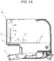
- FIG. 1A is a side view illustrating an example of a stapler according to a first embodiment
- FIG. 1B is a perspective view illustrating the example of the stapler according to the first embodiment
- FIG. 1C is a front view illustrating the example of the stapler according to the first embodiment
- FIG. 1D is a side sectional view illustrating the example of the stapler according to the first embodiment.
- a stapler 1A includes a forming plate 2 for shaping the staple 10 and a driver plate 3 for driving out a staple 10 shaped by the forming plate 2. Further, the stapler 1A includes a feeding portion 4 that feeds a staple sheet 11 to which a plurality of staples 10 are connected, and a face plate 5 with which the staple sheet 11 fed by the feeding portion 4 comes into contact. The stapler 1A further includes a bending portion 7 that bends a first staple foot 10b, which is one leg portion, and a second staple foot 10c, which is the other leg portion, of the staple 10 driven out by a driver.
- the forming plate 2 shapes a leading staple 10 of the staple sheet 11, which is formed by connecting a plurality of staples 10 extending linearly in a direction orthogonal to an axial direction of the staples 10, into a U-shape (U shape or gate shape), when viewed from a connection direction of the staples 10.
- the face plate 5 is provided at a position facing the leading staple 10 in the connection direction of the staples 10.
- the leading staple 10 facing the face plate 5 is the staple 10 before being shaped by the forming plate 2.
- the face plate 5 is provided at least at a position facing the leading staple 10 before being shaped.
- a first staple foot (leg portion) 10b bent in a first direction indicated by an arrow A1 is formed on one end portion of a staple crown 10a, and a second staple foot (leg portion) 10c bent in the first direction is formed on the other end portion of the staple crown 10a.
- the above-described form of the shaped staple 10 is referred to as a U-shape.
- the axial direction extending linearly is a longitudinal direction, and a direction orthogonal to the axial direction is a short direction.
- a predetermined length range thereof from one end portion in the longitudinal direction is shaped by the forming plate 2 to become the first staple foot 10b.
- a range to be the first staple foot 10b is referred to as a first staple foot formation portion 10d.
- a predetermined length range thereof from the other end portion in the longitudinal direction is shaped by the forming plate 2 to become the second staple foot 10c.
- a range to be the second staple foot 10c is referred to as a second staple foot formation portion 10e.
- the plurality of staples 10 before shaping are lined up along the short direction orthogonal to the axial direction, and are separably connected by adhesion or the like.
- a cartridge (not illustrated) accommodating the plurality of stacked staple sheets 11 is removably loaded into the stapler 1A.
- FIG. 2A is a front view illustrating an example of the forming plate
- FIG. 2B is a side view illustrating the example of the forming plate.
- the forming plate 2 is supported so as to be movable in a first direction indicated by the arrow A1 and a second direction indicated by an arrow A2 opposite to the first direction, which are substantially orthogonal to a feeding direction of the staple sheet 11 indicated by an arrow F1 ( FIG. 1B ).
- the first direction is a direction in which the first staple foot 10b and the second staple foot 10c are bent with respect to the staple crown 10a.
- the forming plate 2 includes a first shaping portion 21 that shapes the first staple foot 10b of the staple 10, a second shaping portion 22 that shapes the second staple foot 10c, and a connecting portion 23 that connects the first shaping portion 21 and the second shaping portion 22.
- the forming plate 2 includes a first action portion 24 that receives a force for moving in the first direction indicated by the arrow A1, and a second action portion 25 that receives a force for moving in the second direction indicated by the arrow A2.
- the first shaping portion 21 is configured to be insertable and removable at the position facing the face plate 5 by moving the forming plate 2 in the first direction and the second direction.
- the position facing the face plate 5 is a position facing the face plate 5 in a part facing a staple 10 before being shaped to be described later, that is, a position facing the face plate 5 in a feeding path of the staple sheet 11 (the staple 10).
- the first shaping portion 21 moves in the first direction to be inserted into the position facing the face plate 5 at a portion facing the staple 10 before being shaped.
- the first shaping portion 21 is configured to be inserted into the position facing the face plate 5 to bend a part of the leading staple 10 to shape the first staple foot 10b, and move in the second direction after shaping the staple 10 to retreat from the position facing the face plate 5.
- the second shaping portion 22 is configured to be insertable and removable at the position facing the face plate 5 by moving the forming plate 2 in the first direction and the second direction. When the face plate 5 has a shape extending along the first direction and the second direction, the second shaping portion 22 moves in the first direction to be inserted into the position facing the face plate 5 at a portion facing the staple 10 before being shaped.
- the second shaping portion 22 is configured to be inserted into the position facing the face plate 5 to bend another part of the leading staple 10 to shape the second staple foot 10c, and move in the second direction after shaping the staple 10 to retreat from the position facing the face plate 5. Accordingly, by moving the forming plate 2 in the first direction, the first shaping portion 21 and the second shaping portion 22 protrude to a feeding path of the staple sheet 11 fed by the feeding portion 4. When the forming plate 2 moves in the second direction, the first shaping portion 21 and the second shaping portion 22 retreat from the feeding path of the staple sheet 11.
- the first shaping portion 21 and the second shaping portion 22 protrude from the connecting portion 23 in the first direction at an interval corresponding to an outer width L0 ( FIG. 1C ) of the staple crown 10a.
- the outer width L0 of the staple crown 10a is a length from an outer side of the first staple foot 10b of the staple 10 to an outer side of the second staple foot 10c.
- a first front end portion 21a that protrudes the most in the first direction is formed in an outer end portion on a side opposite to a side facing the second shaping portion 22.
- a first rear end portion 21b recessed in the second direction from the first front end portion 21a is formed in an inner end portion facing the second shaping portion 22.
- a second front end portion 22a that protrudes most in the first direction is formed in an outer end portion on a side opposite to a side facing the first shaping portion 21.
- a second rear end portion 22b recessed in the second direction from the second front end portion 22a is formed on an inner end portion facing the first shaping portion 21.
- the second shaping portion 22 is configured such that a length of the second shaping portion 22 along an insertion and removal direction in which the second shaping portion 22 is inserted and removed at the position facing the face plate 5 is longer than a length of the first shaping portion 21 in the insertion and removal direction.
- the length of the first shaping portion 21 along the insertion and removal direction is a length from the second action portion 25 to the first front end portion 21a in the first direction.
- the length of the second shaping portion 22 along the insertion and removal direction is a length from the second action portion 25 to the second front end portion 22a along the first direction.
- a length L2 along the first direction from the second action portion 25 to the second front end portion 22a of the second shaping portion 22 is longer than a length L1 along the first direction from the second action portion 25 to the first front end portion 21a of the first shaping portion 21. Accordingly, the second shaping portion 22 is configured such that, when the forming plate 2 moves in the second direction, the first front end portion 21a of the first shaping portion 21 retracts from the position facing the face plate 5, and then the second front end portion 22a retracts from the position facing the face plate 5.
- the forming plate 2 is configured such that a length L11 to the first rear end portion 21b of the first shaping portion 21 and a length L12 to the second rear end portion 22b of the second shaping portion 22 are equal.
- the length L11 of the first shaping portion 21 to the first rear end portion 21b is a length along the first direction from the first action portion 24 to the first rear end portion 21b.
- the length L12 of the second shaping portion 22 to the second rear end portion 22b is a length along the first direction from the first action portion 24 to the second rear end portion 22b.
- a first front end surface 21c which is a front end portion connecting the first front end portion 21a and the first rear end portion 21b is inclined in an insertion direction from an inner side toward the outside.
- the first front end surface 21c forms an inclined surface of the first shaping portion 21.
- a second front end surface 22c which is a front end portion connecting the second front end portion 22a and the second rear end portion 22b is inclined in the insertion direction from the inner side toward the outside.
- the second front end surface 22c forms an inclined surface of the second shaping portion 22.
- the inclined surface of the first shaping portion 21 has an inclination angle different from that of the inclined surface of the second shaping portion 22.
- the forming plate 2 is configured such that an inclination angle ⁇ 2 of the second front end surface 22c connecting the second front end portion 22a and the second rear end portion 22b of the second shaping portion 22 is larger than an inclination angle ⁇ 1 of the first front end surface 21c connecting the first front end portion 21a and the first rear end portion 21b of the first shaping portion 21.
- the first rear end portion 21b which is at a rear end position of the inclined surface of the first shaping portion 21 in the insertion and removal direction, is set at the same or substantially the same position as the second rear end portion 22b, which is at a rear end position of the inclined surface of the second shaping portion 22 in the insertion and removal direction.
- long hole portions 26 extending along the first direction and the second direction are formed in one side portion on a side where the first shaping portion 21 is formed and the other side portion on a side where the second shaping portion 22 is formed.
- the first action portion 24 is formed of a surface at an end portion of the long hole portion 26 in the first direction.
- the second action portion 25 is formed of a surface at an end portion of the long hole portion 26 in the second direction.
- driver plate 3 the feeding portion 4, and the face plate 5 will be described with reference to FIGS. 1B , 1C , and 1D .
- the driver plate 3 is provided downstream of the forming plate 2 in the feeding direction of the staple sheet 11 indicated by the arrow F1.
- the driver plate 3 is provided with respect to the forming plate 2 with a gap corresponding to one width of the staple 10 in the short direction.
- the driver plate 3 is supported so as to be movable independently of the forming plate 2 in the first direction substantially orthogonal to the feeding direction of the staple sheet 11 and the second direction opposite to the first direction.
- the driver plate 3 is configured to be insertable into and removable from the feeding path of the staple sheet 11 including the staple crown 10a, and is configured to come into contact with the staple crown 10a by being inserted into the feeding path of the staple sheet 11 to drive out the staple 10, and to retract from the feeding path of the staple sheet 11 after the staple 10 is driven out.
- the driver plate 3 includes action portions 31 that receive a force for moving in the first direction and a force for moving in the second direction.
- the action portion 31 is a hole having a shape formed by combining a semicircular shape and a quadrangular shape.
- the stapler 1A includes a shaft 6 that moves the forming plate 2 and the driver plate 3 in the first direction and the second direction.
- the shaft 6 is an example of a transmission member, and is driven by a drive portion (not illustrated) including a motor, a gear, and the like, and moves in the first direction and the second direction.
- the shaft 6 is inserted into the long hole portion 26 of the forming plate 2 and the action portion 31 of the driver plate 3.
- the action portion 31 of the driver plate 3 includes a hole having a shape formed by combining a semicircular portion having a diameter substantially equal to a diameter of the shaft 6 and a quadrangular portion connected to the semicircular portion. Accordingly, the driver plate 3 follows a movement of the shaft 6 in the first direction and the second direction.
- a length of the long hole portion 26 of the forming plate 2 in the longitudinal direction along the first direction and the second direction is longer than the diameter of the shaft 6. Accordingly, when the shaft 6 moving in the first direction comes into contact with the first action portion 24, the forming plate 2 moves in the first direction in conjunction with the driver plate 3. In addition, when the shaft 6 moving in the second direction comes into contact with the second action portion 25, the forming plate 2 moves in the second direction in conjunction with the driver plate 3. Further, when the shaft 6 is not in contact with any of the first action portion 24 and the second action portion 25, the forming plate 2 is not interlocked with the driver plate 3 and is in a stopped state.
- the feeding portion 4 feeds the staple sheet 11 in the direction of the arrow F1 by moving a claw portion 40 engaged with the staple sheet 11 in the direction of the arrow F 1.
- the feeding portion 4 may be configured to be urged by an urging member such as a spring (not illustrated), or may be configured to be driven by a drive portion (not illustrated) including a motor, a gear, and the like.
- the face plate 5 is provided downstream of the forming plate 2 and the driver plate 3 in the feeding direction of the staple sheet 11 indicated by the arrow F1.
- the face plate 5 closes the feeding path of the staple sheet 11 by the feeding portion 4, and comes into contact with the first staple foot formation portion 10d and the second staple foot formation portion 10e of the staple 10 before shaping.
- FIG. 3A is a front view illustrating a relationship between the forming plate and the driver plate and the dimension of the staple
- FIG. 3B is a top view illustrating the relationship between the forming plate and the driver plate and the dimension of the staple
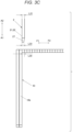
- FIG. 3C is a side view illustrating a relationship between the forming plate and the dimension of the staple.
- a thickness L20 of the staple 10 illustrated in FIG. 3A is about 0.35 mm in this example.
- a length L22 by which the second front end portion 22a of the second shaping portion 22 protrudes in the first direction with respect to the first front end portion 21a of the first shaping portion 21 is about 0.5 mm. This dimensional difference is set so that the second shaping portion 22 remains in the feeding path of the staple sheet 11 at a timing at which the first shaping portion 21 retreats from the feeding path of the staple sheet 11.
- a length L21 by which the driver plate 3 retreats in the second direction with respect to the first front end portion 21a of the first shaping portion 21 is about 1 mm. This dimensional difference is set so that the driver plate 3 retracts from the feeding path of the staple sheet 11 before the timing at which the first shaping portion 21 retracts from the feeding path of the staple sheet 11.
- a width L30 of the staple 10 illustrated in FIGS. 3B and 3C is about 0.5 mm in this example.
- thicknesses L31 of the first shaping portion 21 and the second shaping portion 22 of the forming plate 2 is each about 0.5 mm. This dimension is for shaping one staple 10 with the forming plate 2.
- a thickness L32 of the driver plate 3 is about 0.5 mm. This dimension is for driving out one staple 10 by the driver plate 3.
- the first shaping portion 21 and the second shaping portion 22 of the forming plate 2 have a tapered shape in which a rear side is narrowed toward the first direction as indicated by the arrow F2, and a thickness L33 of a tip end portion 27 is about 0.4 mm. This dimension is intended to prevent the forming plate 2 from being caught on the staple 10 before shaping, behind the staple 10 to be shaped.
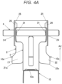
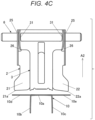
- FIGS. 4A , 4B , and 4C are front views illustrating an example of an operation of the stapler according to the first embodiment.
- FIGS. 5A, 5B, and 5C are top sectional views illustrating an example of the operation of the stapler according to the first embodiment.
- the driver plate 3 When the shaft 6 is driven by the drive portion (not illustrated) to move in the first direction, the driver plate 3 receives the force for moving the driver plate 3 in the first direction by the action portion 31. When the driver plate 3 moves in the first direction in a state where the shaped staple 10 positioned at the head of the staple sheet 11 is positioned, the shaped staple 10 is driven out in a movement path of the driver plate 3.
- the forming plate 2 is configured such that the length L2 to the second front end portion 22a of the second shaping portion 22 is longer than the length L1 to the first front end portion 21a of the first shaping portion 21.
- the second shaping portion 22 first comes into contact with the second staple foot formation portion 10e of the staple 10 before shaping due to the difference in length between the first shaping portion 21 and the second shaping portion 22.
- the second staple foot formation portion 10e of the staple 10 is bent in the first direction.
- the first shaping portion 21 comes into contact with the first staple foot formation portion 10d of the staple 10 before shaping.
- the first staple foot formation portion 10d is bent in the first direction in addition to the second staple foot formation portion 10e of the staple 10.
- timings at which the first staple foot formation portion 10d and the second staple foot formation portion 10e of the staple 10 start to be bent can be shifted from each other based on the difference in length between the first shaping portion 21 and the second shaping portion 22 of the forming plate 2, and a load applied to the forming plate 2 can be distributed.
- the first shaping portion 21 and the second shaping portion 22 protrude to the feeding path of the staple sheet 11. Accordingly, in the forming plate 2, the first shaping portion 21 enters between the face plate 5 and the first staple foot formation portion 10d of the staple 10 before shaping, and the second shaping portion 22 enters between the face plate 5 and the second staple foot formation portion 10e of the staple 10 before shaping.
- the forming plate 2 is configured such that the length L11 to the first rear end portion 21b of the first shaping portion 21 and the length L12 to the second rear end portion 22b of the second shaping portion 22 are equal. Accordingly, a timing at which the first staple foot 10b finishes bending with respect to the staple crown 10a coincides with a timing at which the second staple foot 10c finishes bending with respect to the staple crown 10a, and symmetry of a forming shape is maintained.
- the driver plate 3 When the shaft 6 is driven by the drive portion (not illustrated) to move in the second direction, the driver plate 3 receives the force for moving the driver plate 3 in the second direction by the action portion 31. When the driver plate 3 moves in the second direction, the driver plate 3 separates from the staple 10 driven into a sheet (not illustrated).
- the first shaping portion 21 and the second shaping portion 22 retract from the position facing the face plate 5 of the portion facing the staple 10 before being shaped after a timing at which the driver plate 3 retracts from the feeding path of the staple sheet 11.
- the first shaping portion 21 first retracts from the feeding path of the staple sheet 11 based on the difference in length between the first shaping portion 21 and the second shaping portion 22.
- the second shaping portion 22 remains in the feeding path of the staple sheet 11 at the timing at which the first shaping portion 21 retreats from the feeding path of the staple sheet 11.
- the first staple foot formation portion 10d of the staple 10 before shaping approaches the face plate 5.
- the first staple foot formation portion 10d of the staple 10 before shaping may come into contact with the face plate 5.
- sound collision sound
- the second staple foot formation portion 10e of the staple 10 before shaping is held in contact with the second shaping portion 22 of the forming plate 2.
- the second shaping portion 22 retreats from the feeding path of the staple sheet 11.
- the first staple foot formation portion 10d of the staple 10 before shaping approaches the face plate 5 before the second staple foot formation portion 10e of the staple 10 before shaping
- the first staple foot formation portion 10d of the staple 10 before shaping comes into contact with the face plate 5 before the timing at which the second staple foot formation portion 10e of the staple 10 before shaping comes into contact with the face plate 5. Accordingly, the timing of generating sound is dispersed.
- the staple crown 10a of the shaped staple 10 positioned at the head of the staple sheet 11 a side close to the first staple foot 10b first comes into contact with the face plate 5, and then a side close to the second staple foot 10c comes into contact with the face plate 5.
- the timing of generating the sound is dispersed, it is possible to reduce the generated sound (collision sound) as compared with a case where sound is generated when the first staple foot formation portion 10d and the second staple foot formation portion 10e of the staple 10 before shaping come into contact with the face plate 5 at the same timing.
- FIGS. 6A and 6B are front views illustrating a modification of the forming plate.
- a forming plate 2B is supported so as to be movable in the first direction indicated by the arrow A1 and the second direction indicated by the arrow A2 opposite to the first direction.
- the forming plate 2B includes the first shaping portion 21 that shapes the first staple foot 10b of the staple 10 illustrated in FIG. 1B and the like, the second shaping portion 22 that shapes the second staple foot 10c, and the connecting portion 23 that connects the first shaping portion 21 and the second shaping portion 22.
- the forming plate 2B includes first action portions 24a and 24b that receive a force for moving in the first direction indicated by the arrow A1, and second action portions 25a and 25b that receive a force for moving in the second direction indicated by the arrow A2.
- the first shaping portion 21 and the second shaping portion 22 have symmetrical shapes, and a protruding length from the first rear end portion 21b of the first shaping portion 21 to the first front end portion 21a is equal to a protruding length from the second rear end portion 22b of the second shaping portion 22 to the second front end portion 22a.
- the forming plate 2B is configured such that the length L21 from the first action portion 24a on the side where the first shaping portion 21 is provided to the first front end portion 21a of the first shaping portion 21 is equal to the length L22 from the first action portion 24b on the side where the second shaping portion 22 is provided to the second front end portion 22a of the second shaping portion 22.
- the forming plate 2B is configured such that the length L2 from the second action portion 25b on the side where the second shaping portion 22 is provided to the second front end portion 22a of the second shaping portion 22 is longer than the length L1 from the second action portion 25a on the side where the first shaping portion 21 is provided to the first front end portion 21a of the first shaping portion 21.
- the shaft 6 when the shaft 6 moves in the first direction, the shaft 6 comes into contact with the first action portion 24a on the side where the first shaping portion 21 is provided and the first action portion 24b on the side where the second shaping portion 22 is provided at substantially the same timing.
- the first shaping portion 21 and the second shaping portion 22 come into contact with the staple (not illustrated in FIGS. 6A and 6B ) at substantially the same timing.
- the staple When the forming plate 2B moves to the shaping position in the first direction from this state, the staple is shaped.
- the forming plate 2B when the shaft 6 moves in the second direction, first, the shaft 6 comes into contact with the second action portion 25a on the side where the first shaping portion 21 is provided. When the shaft 6 further moves in the second direction from this state, the forming plate 2B moves in the second direction on the side where the first shaping portion 21 is provided. Accordingly, the forming plate 2B is rotatably supported along the face plate illustrated in FIG. 1A and the like, and the first front end portion 21a of the first shaping portion 21 is more inclined in the second direction than the second front end portion 22a of the second shaping portion 22.
- the shaft 6 when the shaft 6 further moves in the second direction, the shaft 6 comes into contact with the second action portion 25b on the side where the second shaping portion 22 is provided.
- the forming plate 2B moves in the second direction in the state where the first shaping portion 21 is more inclined in the second direction than the second shaping portion 22.
- the timing at which the second shaping portion 22 retracts from the feeding path of the staple sheet and the timing at which the first shaping portion 21 retracts from the feeding path of the staple sheet are shifted from each other. Accordingly, the timing at which the sound is generated when one end portion side of the staple along the longitudinal direction comes into contact with the face plate illustrated in FIG. 1A or the like can be made different from the timing at which the sound is generated when the other end portion side of the staple along the longitudinal direction comes into contact with the face plate. As a result, it is possible to reduce an increase in sound as compared with a case in which sound is generated when the one end portion side and the other end portion side along the longitudinal direction of the staple come into contact with the face plate at the same timing.
Landscapes
- Engineering & Computer Science (AREA)
- Mechanical Engineering (AREA)
- Life Sciences & Earth Sciences (AREA)
- Forests & Forestry (AREA)
- Portable Nailing Machines And Staplers (AREA)
- Dovetailed Work, And Nailing Machines And Stapling Machines For Wood (AREA)
Abstract
Description
- The present disclosure relates to a stapler that binds a bundle of sheets with a staple.
- There has been proposed a stapler including a staple pusher (feeding portion) that presses connected staples (staple sheet) to which linear staples (linear staples) are bonded in parallel toward a front end plate (face plate), a forming plate that shapes the linear staple into a gate shape (U-shape), and a driver that moves up and down in conjunction with the forming plate and drives out the staple shaped by the forming plate (for example, see Patent Literature 1).
- In such a stapler, when the forming plate is lowered, the forming plate protrudes to the feeding path of the staple to shape the staple. Further, when the forming plate is raised, both of a portion for shaping one side of a straight staple and a portion for shaping the other side of the straight staple in the forming plate are simultaneously retracted from the feeding path of the staple, and when the staple sheet is fed, the shaped staple is moved to a position at which the staple can be driven out by the driver.
- Patent Literature 1:
JPH10-180710A - When the forming plate with which the staple is shaped retracts from the feeding path of the staple sheet, a straight staple positioned immediately behind the shaped staple in the staple sheet fed by the feeding portion comes into contact with the face plate to generate collision sound. At this time, since both of the portion for shaping the one side of the straight staple and the portion for shaping the other side of the straight staple in the forming plate are simultaneously retracted from the feeding path of the staple, and the staple sheet is pressed by a staple pusher in a direction of the face plate, the collision sound is generated at both end portion sides of the straight staple positioned immediately behind the shaped staple, that is, at both portions corresponding to the one side and the other side of the staple before shaping in the straight staple positioned immediately behind the shaped staple.
- In view of the above, the present disclosure provides a stapler capable of reducing sound generated when a staple sheet comes into contact with a face plate.
- The present disclosure discloses a stapler including: a forming plate configured to shape a leading staple of a staple sheet, which is formed by connecting a plurality of staples extending linearly in a direction perpendicular to an axial direction of the staples, into a U-shape, when viewed from a connection direction of the staples; a face plate provided at a position to be face the leading staple in the connection direction; and a feeding portion configured to, after the leading staple is shaped, feed the staple sheet in the connection direction, and configured to bring a linear staple positioned immediately behind the shaped staple into contact with the face plate. The forming plate includes a first shaping portion that is configured to shape one leg portion of the staple forming a part of the U-shape and a second shaping portion that is configured to shape another leg portion thereof forming another part of the U-shape. The first shaping portion is configured to be insertable and removable at a position facing the face plate, configured to shape the one leg portion by bending a part of the leading staple by being inserted at the position facing the face plate, and configured to retract from the position facing the face plate after shaping. The second shaping portion is configured to be insertable and removable at the position facing the face plate, and configured to shape the other leg portion by bending another part of the leading staple by being inserted at the position facing the face plate, and configured to retract from the position facing the face plate after the first shaping portion retracts from the position facing the face plate after shaping.
- The first shaping portion is configured to shape the one leg portion by bending a part of the leading staple by being inserted at the position facing the face plate, and configured to retract from the position facing the face plate after shaping. The second shaping portion is configured to shape the other leg portion by bending another part of the leading staple by being inserted at the position facing the face plate, and configured to retract from the position facing the face plate after the first shaping portion retracts from the position facing the face plate after shaping.
- The second shaping portion retracts from the position facing the face plate after the first shaping portion retracts from the position facing the face plate, so that after one end portion side of the staple along the axial direction of the staple positioned immediately behind the shaped staple comes into contact with the face plate, the other end portion side of the staple comes into contact with the face plate. That is, a timing at which the face plate is brought into contact with the one end portion side to generate sound is different from a timing at which the face plate is brought into contact with the other end portion side to generate sound. As a result, it is possible to reduce the generated sound as compared with a case where sound is generated when the one end portion side and the other end portion side along the axial direction of the staple come into contact with the face plate at the same timing.
-
-
FIG. 1A is a side view illustrating an example of a stapler according to a first embodiment. -
FIG. 1B is a perspective view illustrating the example of the stapler according to the first embodiment. -
FIG. 1C is a front view illustrating the example of the stapler according to the first embodiment. -
FIG. 1D is a side sectional view illustrating the example of the stapler according to the first embodiment. -
FIG. 2A is a front view illustrating an example of a forming plate. -
FIG. 2B is a side view illustrating the example of the forming plate. -
FIG. 3A is a front view illustrating a relationship between the forming plate and a driver plate and a dimension of a staple. -
FIG. 3B is a top view illustrating the relationship between the forming plate and the driver plate and the dimension of the staple. -
FIG. 3C is a side view illustrating a relationship between the forming plate and the dimension of the staple. -
FIG. 4A is a front view illustrating an example of an operation of the stapler according to the first embodiment. -
FIG. 4B is a front view illustrating the example of the operation of the stapler according to the first embodiment. -
FIG. 4C is a front view illustrating the example of the operation of the stapler according to the first embodiment. -
FIG. 5A is a top sectional view illustrating the example of the operation of the stapler according to the first embodiment. -
FIG. 5B is a top sectional view illustrating an example of the operation of the stapler according to the first embodiment. -
FIG. 5C is a top sectional view illustrating the example of the operation of the stapler according to the first embodiment. -
FIG. 6A is a front view illustrating a modification of the forming plate. -
FIG. 6B is a front view illustrating the modification of the forming plate. - Hereinafter, an embodiment of a stapler according to the present disclosure will be described with reference to the drawings.
-
FIG. 1A is a side view illustrating an example of a stapler according to a first embodiment,FIG. 1B is a perspective view illustrating the example of the stapler according to the first embodiment,FIG. 1C is a front view illustrating the example of the stapler according to the first embodiment, andFIG. 1D is a side sectional view illustrating the example of the stapler according to the first embodiment. - A
stapler 1A includes a formingplate 2 for shaping thestaple 10 and adriver plate 3 for driving out astaple 10 shaped by the formingplate 2. Further, thestapler 1A includes afeeding portion 4 that feeds astaple sheet 11 to which a plurality ofstaples 10 are connected, and aface plate 5 with which thestaple sheet 11 fed by thefeeding portion 4 comes into contact. Thestapler 1A further includes a bending portion 7 that bends a firststaple foot 10b, which is one leg portion, and a secondstaple foot 10c, which is the other leg portion, of the staple 10 driven out by a driver. The formingplate 2 shapes a leadingstaple 10 of thestaple sheet 11, which is formed by connecting a plurality ofstaples 10 extending linearly in a direction orthogonal to an axial direction of thestaples 10, into a U-shape (U shape or gate shape), when viewed from a connection direction of thestaples 10. Theface plate 5 is provided at a position facing the leadingstaple 10 in the connection direction of thestaples 10. The leadingstaple 10 facing theface plate 5 is the staple 10 before being shaped by the formingplate 2. Theface plate 5 is provided at least at a position facing the leadingstaple 10 before being shaped. After the leadingstaple 10 is shaped, the feedingportion 4 feeds thestaple sheet 11 in the connection direction of the staple 10, and brings thelinear staple 10 positioned immediately behind the shapedstaple 10 into contact with theface plate 5. - By shaping the staple 10 using the forming
plate 2, a first staple foot (leg portion) 10b bent in a first direction indicated by an arrow A1 is formed on one end portion of astaple crown 10a, and a second staple foot (leg portion) 10c bent in the first direction is formed on the other end portion of thestaple crown 10a. The above-described form of the shapedstaple 10 is referred to as a U-shape. - In the staple 10 before shaping, the axial direction extending linearly is a longitudinal direction, and a direction orthogonal to the axial direction is a short direction.
- In the staple 10 before shaping, a predetermined length range thereof from one end portion in the longitudinal direction is shaped by the forming
plate 2 to become the firststaple foot 10b. In the staple 10 before shaping, a range to be the firststaple foot 10b is referred to as a first staplefoot formation portion 10d. In addition, in the staple 10 before shaping, a predetermined length range thereof from the other end portion in the longitudinal direction is shaped by the formingplate 2 to become the secondstaple foot 10c. In the staple 10 before shaping, a range to be the secondstaple foot 10c is referred to as a second staplefoot formation portion 10e. - In the
staple sheet 11, the plurality ofstaples 10 before shaping are lined up along the short direction orthogonal to the axial direction, and are separably connected by adhesion or the like. - A cartridge (not illustrated) accommodating the plurality of
stacked staple sheets 11 is removably loaded into thestapler 1A. -
FIG. 2A is a front view illustrating an example of the forming plate, andFIG. 2B is a side view illustrating the example of the forming plate. - The forming
plate 2 is supported so as to be movable in a first direction indicated by the arrow A1 and a second direction indicated by an arrow A2 opposite to the first direction, which are substantially orthogonal to a feeding direction of thestaple sheet 11 indicated by an arrow F1 (FIG. 1B ). As described above, the first direction is a direction in which the firststaple foot 10b and the secondstaple foot 10c are bent with respect to thestaple crown 10a. - The forming
plate 2 includes afirst shaping portion 21 that shapes the firststaple foot 10b of the staple 10, asecond shaping portion 22 that shapes the secondstaple foot 10c, and a connectingportion 23 that connects thefirst shaping portion 21 and thesecond shaping portion 22. - The forming
plate 2 includes afirst action portion 24 that receives a force for moving in the first direction indicated by the arrow A1, and asecond action portion 25 that receives a force for moving in the second direction indicated by the arrow A2. - The
first shaping portion 21 is configured to be insertable and removable at the position facing theface plate 5 by moving the formingplate 2 in the first direction and the second direction. The position facing theface plate 5 is a position facing theface plate 5 in a part facing a staple 10 before being shaped to be described later, that is, a position facing theface plate 5 in a feeding path of the staple sheet 11 (the staple 10). When theface plate 5 has a shape extending along the first direction and the second direction, thefirst shaping portion 21 moves in the first direction to be inserted into the position facing theface plate 5 at a portion facing the staple 10 before being shaped. Thefirst shaping portion 21 is configured to be inserted into the position facing theface plate 5 to bend a part of the leadingstaple 10 to shape the firststaple foot 10b, and move in the second direction after shaping the staple 10 to retreat from the position facing theface plate 5. Thesecond shaping portion 22 is configured to be insertable and removable at the position facing theface plate 5 by moving the formingplate 2 in the first direction and the second direction. When theface plate 5 has a shape extending along the first direction and the second direction, thesecond shaping portion 22 moves in the first direction to be inserted into the position facing theface plate 5 at a portion facing the staple 10 before being shaped. Thesecond shaping portion 22 is configured to be inserted into the position facing theface plate 5 to bend another part of the leadingstaple 10 to shape the secondstaple foot 10c, and move in the second direction after shaping the staple 10 to retreat from the position facing theface plate 5. Accordingly, by moving the formingplate 2 in the first direction, thefirst shaping portion 21 and thesecond shaping portion 22 protrude to a feeding path of thestaple sheet 11 fed by the feedingportion 4. When the formingplate 2 moves in the second direction, thefirst shaping portion 21 and thesecond shaping portion 22 retreat from the feeding path of thestaple sheet 11. - In the forming
plate 2, thefirst shaping portion 21 and thesecond shaping portion 22 protrude from the connectingportion 23 in the first direction at an interval corresponding to an outer width L0 (FIG. 1C ) of thestaple crown 10a. The outer width L0 of thestaple crown 10a is a length from an outer side of the firststaple foot 10b of the staple 10 to an outer side of the secondstaple foot 10c. - In the
first shaping portion 21, a firstfront end portion 21a that protrudes the most in the first direction is formed in an outer end portion on a side opposite to a side facing thesecond shaping portion 22. In addition, in thefirst shaping portion 21, a firstrear end portion 21b recessed in the second direction from the firstfront end portion 21a is formed in an inner end portion facing thesecond shaping portion 22. - In the
second shaping portion 22, a secondfront end portion 22a that protrudes most in the first direction is formed in an outer end portion on a side opposite to a side facing thefirst shaping portion 21. In addition, in thesecond shaping portion 22, a secondrear end portion 22b recessed in the second direction from the secondfront end portion 22a is formed on an inner end portion facing thefirst shaping portion 21. - The
second shaping portion 22 is configured such that a length of thesecond shaping portion 22 along an insertion and removal direction in which thesecond shaping portion 22 is inserted and removed at the position facing theface plate 5 is longer than a length of thefirst shaping portion 21 in the insertion and removal direction. In the present embodiment, the length of thefirst shaping portion 21 along the insertion and removal direction is a length from thesecond action portion 25 to the firstfront end portion 21a in the first direction. The length of thesecond shaping portion 22 along the insertion and removal direction is a length from thesecond action portion 25 to the secondfront end portion 22a along the first direction. - A length L2 along the first direction from the
second action portion 25 to the secondfront end portion 22a of thesecond shaping portion 22 is longer than a length L1 along the first direction from thesecond action portion 25 to the firstfront end portion 21a of thefirst shaping portion 21. Accordingly, thesecond shaping portion 22 is configured such that, when the formingplate 2 moves in the second direction, the firstfront end portion 21a of thefirst shaping portion 21 retracts from the position facing theface plate 5, and then the secondfront end portion 22a retracts from the position facing theface plate 5. - The forming
plate 2 is configured such that a length L11 to the firstrear end portion 21b of thefirst shaping portion 21 and a length L12 to the secondrear end portion 22b of thesecond shaping portion 22 are equal. - The length L11 of the
first shaping portion 21 to the firstrear end portion 21b is a length along the first direction from thefirst action portion 24 to the firstrear end portion 21b. The length L12 of thesecond shaping portion 22 to the secondrear end portion 22b is a length along the first direction from thefirst action portion 24 to the secondrear end portion 22b. - In the
first shaping portion 21, a firstfront end surface 21c which is a front end portion connecting the firstfront end portion 21a and the firstrear end portion 21b is inclined in an insertion direction from an inner side toward the outside. The firstfront end surface 21c forms an inclined surface of thefirst shaping portion 21. In thesecond shaping portion 22, a secondfront end surface 22c which is a front end portion connecting the secondfront end portion 22a and the secondrear end portion 22b is inclined in the insertion direction from the inner side toward the outside. The secondfront end surface 22c forms an inclined surface of thesecond shaping portion 22. The inclined surface of thefirst shaping portion 21 has an inclination angle different from that of the inclined surface of thesecond shaping portion 22. That is, the formingplate 2 is configured such that an inclination angle α2 of the secondfront end surface 22c connecting the secondfront end portion 22a and the secondrear end portion 22b of thesecond shaping portion 22 is larger than an inclination angle α1 of the firstfront end surface 21c connecting the firstfront end portion 21a and the firstrear end portion 21b of thefirst shaping portion 21. The firstrear end portion 21b, which is at a rear end position of the inclined surface of thefirst shaping portion 21 in the insertion and removal direction, is set at the same or substantially the same position as the secondrear end portion 22b, which is at a rear end position of the inclined surface of thesecond shaping portion 22 in the insertion and removal direction. - In the forming
plate 2,long hole portions 26 extending along the first direction and the second direction are formed in one side portion on a side where thefirst shaping portion 21 is formed and the other side portion on a side where thesecond shaping portion 22 is formed. Thefirst action portion 24 is formed of a surface at an end portion of thelong hole portion 26 in the first direction. Thesecond action portion 25 is formed of a surface at an end portion of thelong hole portion 26 in the second direction. - Next, the
driver plate 3, the feedingportion 4, and theface plate 5 will be described with reference toFIGS. 1B ,1C , and1D . - The
driver plate 3 is provided downstream of the formingplate 2 in the feeding direction of thestaple sheet 11 indicated by the arrow F1. Thedriver plate 3 is provided with respect to the formingplate 2 with a gap corresponding to one width of the staple 10 in the short direction. Thedriver plate 3 is supported so as to be movable independently of the formingplate 2 in the first direction substantially orthogonal to the feeding direction of thestaple sheet 11 and the second direction opposite to the first direction. Thedriver plate 3 is configured to be insertable into and removable from the feeding path of thestaple sheet 11 including thestaple crown 10a, and is configured to come into contact with thestaple crown 10a by being inserted into the feeding path of thestaple sheet 11 to drive out the staple 10, and to retract from the feeding path of thestaple sheet 11 after the staple 10 is driven out. - The
driver plate 3 includesaction portions 31 that receive a force for moving in the first direction and a force for moving in the second direction. Theaction portion 31 is a hole having a shape formed by combining a semicircular shape and a quadrangular shape. - The
stapler 1A includes ashaft 6 that moves the formingplate 2 and thedriver plate 3 in the first direction and the second direction. Theshaft 6 is an example of a transmission member, and is driven by a drive portion (not illustrated) including a motor, a gear, and the like, and moves in the first direction and the second direction. Theshaft 6 is inserted into thelong hole portion 26 of the formingplate 2 and theaction portion 31 of thedriver plate 3. - The
action portion 31 of thedriver plate 3 includes a hole having a shape formed by combining a semicircular portion having a diameter substantially equal to a diameter of theshaft 6 and a quadrangular portion connected to the semicircular portion. Accordingly, thedriver plate 3 follows a movement of theshaft 6 in the first direction and the second direction. - In contrast, a length of the
long hole portion 26 of the formingplate 2 in the longitudinal direction along the first direction and the second direction is longer than the diameter of theshaft 6. Accordingly, when theshaft 6 moving in the first direction comes into contact with thefirst action portion 24, the formingplate 2 moves in the first direction in conjunction with thedriver plate 3. In addition, when theshaft 6 moving in the second direction comes into contact with thesecond action portion 25, the formingplate 2 moves in the second direction in conjunction with thedriver plate 3. Further, when theshaft 6 is not in contact with any of thefirst action portion 24 and thesecond action portion 25, the formingplate 2 is not interlocked with thedriver plate 3 and is in a stopped state. - The feeding
portion 4 feeds thestaple sheet 11 in the direction of the arrow F1 by moving aclaw portion 40 engaged with thestaple sheet 11 in the direction of thearrow F 1. The feedingportion 4 may be configured to be urged by an urging member such as a spring (not illustrated), or may be configured to be driven by a drive portion (not illustrated) including a motor, a gear, and the like. - The
face plate 5 is provided downstream of the formingplate 2 and thedriver plate 3 in the feeding direction of thestaple sheet 11 indicated by the arrow F1. Theface plate 5 closes the feeding path of thestaple sheet 11 by the feedingportion 4, and comes into contact with the first staplefoot formation portion 10d and the second staplefoot formation portion 10e of the staple 10 before shaping. -
FIG. 3A is a front view illustrating a relationship between the forming plate and the driver plate and the dimension of the staple,FIG. 3B is a top view illustrating the relationship between the forming plate and the driver plate and the dimension of the staple, andFIG. 3C is a side view illustrating a relationship between the forming plate and the dimension of the staple. - A thickness L20 of the staple 10 illustrated in
FIG. 3A is about 0.35 mm in this example. In contrast, a length L22 by which the secondfront end portion 22a of thesecond shaping portion 22 protrudes in the first direction with respect to the firstfront end portion 21a of thefirst shaping portion 21 is about 0.5 mm. This dimensional difference is set so that thesecond shaping portion 22 remains in the feeding path of thestaple sheet 11 at a timing at which thefirst shaping portion 21 retreats from the feeding path of thestaple sheet 11. - A length L21 by which the
driver plate 3 retreats in the second direction with respect to the firstfront end portion 21a of thefirst shaping portion 21 is about 1 mm. This dimensional difference is set so that thedriver plate 3 retracts from the feeding path of thestaple sheet 11 before the timing at which thefirst shaping portion 21 retracts from the feeding path of thestaple sheet 11. - A width L30 of the staple 10 illustrated in
FIGS. 3B and3C is about 0.5 mm in this example. In contrast, thicknesses L31 of thefirst shaping portion 21 and thesecond shaping portion 22 of the formingplate 2 is each about 0.5 mm. This dimension is for shaping onestaple 10 with the formingplate 2. A thickness L32 of thedriver plate 3 is about 0.5 mm. This dimension is for driving out onestaple 10 by thedriver plate 3. Further, thefirst shaping portion 21 and thesecond shaping portion 22 of the formingplate 2 have a tapered shape in which a rear side is narrowed toward the first direction as indicated by the arrow F2, and a thickness L33 of atip end portion 27 is about 0.4 mm. This dimension is intended to prevent the formingplate 2 from being caught on the staple 10 before shaping, behind the staple 10 to be shaped. -
FIGS. 4A ,4B , and4C are front views illustrating an example of an operation of the stapler according to the first embodiment.FIGS. 5A, 5B, and 5C are top sectional views illustrating an example of the operation of the stapler according to the first embodiment. - When the
shaft 6 is driven by the drive portion (not illustrated) to move in the first direction, thedriver plate 3 receives the force for moving thedriver plate 3 in the first direction by theaction portion 31. When thedriver plate 3 moves in the first direction in a state where the shapedstaple 10 positioned at the head of thestaple sheet 11 is positioned, the shapedstaple 10 is driven out in a movement path of thedriver plate 3. - When the
shaft 6 moving in the first direction comes into contact with thefirst action portion 24, the formingplate 2 moves in the first direction in conjunction with thedriver plate 3. - The forming
plate 2 is configured such that the length L2 to the secondfront end portion 22a of thesecond shaping portion 22 is longer than the length L1 to the firstfront end portion 21a of thefirst shaping portion 21. When the formingplate 2 moves in the first direction from a standby position, thesecond shaping portion 22 first comes into contact with the second staplefoot formation portion 10e of the staple 10 before shaping due to the difference in length between thefirst shaping portion 21 and thesecond shaping portion 22. When the formingplate 2 moves in the first direction from this state, the second staplefoot formation portion 10e of the staple 10 is bent in the first direction. - When the forming
plate 2 moves in the first direction to a position where the second staplefoot formation portion 10e of the staple 10 is bent in the first direction by a predetermined amount, thefirst shaping portion 21 comes into contact with the first staplefoot formation portion 10d of the staple 10 before shaping. When the formingplate 2 moves in the first direction from this state, the first staplefoot formation portion 10d is bent in the first direction in addition to the second staplefoot formation portion 10e of thestaple 10. - In this manner, timings at which the first staple
foot formation portion 10d and the second staplefoot formation portion 10e of the staple 10 start to be bent can be shifted from each other based on the difference in length between thefirst shaping portion 21 and thesecond shaping portion 22 of the formingplate 2, and a load applied to the formingplate 2 can be distributed. - When the forming
plate 2 moves to a shaping position in the first direction, thefirst shaping portion 21 and thesecond shaping portion 22 protrude to the feeding path of thestaple sheet 11. Accordingly, in the formingplate 2, thefirst shaping portion 21 enters between theface plate 5 and the first staplefoot formation portion 10d of the staple 10 before shaping, and thesecond shaping portion 22 enters between theface plate 5 and the second staplefoot formation portion 10e of the staple 10 before shaping. - The forming
plate 2 is configured such that the length L11 to the firstrear end portion 21b of thefirst shaping portion 21 and the length L12 to the secondrear end portion 22b of thesecond shaping portion 22 are equal. Accordingly, a timing at which the firststaple foot 10b finishes bending with respect to thestaple crown 10a coincides with a timing at which the secondstaple foot 10c finishes bending with respect to thestaple crown 10a, and symmetry of a forming shape is maintained. - When the
shaft 6 is driven by the drive portion (not illustrated) to move in the second direction, thedriver plate 3 receives the force for moving thedriver plate 3 in the second direction by theaction portion 31. When thedriver plate 3 moves in the second direction, thedriver plate 3 separates from the staple 10 driven into a sheet (not illustrated). - When the
shaft 6 moving in the second direction comes into contact with thesecond action portion 25, the formingplate 2 moves in the second direction in conjunction with thedriver plate 3. - When the forming
plate 2 moves by a predetermined amount in the second direction from the shaping position, thefirst shaping portion 21 and thesecond shaping portion 22 retract from the position facing theface plate 5 of the portion facing the staple 10 before being shaped after a timing at which thedriver plate 3 retracts from the feeding path of thestaple sheet 11. In the formingplate 2, thefirst shaping portion 21 first retracts from the feeding path of thestaple sheet 11 based on the difference in length between thefirst shaping portion 21 and thesecond shaping portion 22. In the formingplate 2, thesecond shaping portion 22 remains in the feeding path of thestaple sheet 11 at the timing at which thefirst shaping portion 21 retreats from the feeding path of thestaple sheet 11. - In this state, when the
staple sheet 11 is fed in the direction of the arrow F1 by the feedingportion 4, the first staplefoot formation portion 10d of the staple 10 before shaping approaches theface plate 5. Alternatively, the first staplefoot formation portion 10d of the staple 10 before shaping may come into contact with theface plate 5. When the first staplefoot formation portion 10d comes into contact with theface plate 5, sound (collision sound) is generated when the first staplefoot formation portion 10d comes into contact with theface plate 5. On the other hand, the second staplefoot formation portion 10e of the staple 10 before shaping is held in contact with thesecond shaping portion 22 of the formingplate 2. - When the forming
plate 2 moves to the standby position in the second direction, thesecond shaping portion 22 retreats from the feeding path of thestaple sheet 11. - In this state, when the
staple sheet 11 is fed in the direction of the arrow F1 by the feedingportion 4, the second staplefoot formation portion 10e of the staple 10 before shaped positioned immediately behind the shapedstaple 10 comes into contact with theface plate 5. This generates sound (collision sound) when the second staplefoot formation portion 10e comes into contact with theface plate 5. When the first staplefoot formation portion 10d of the staple 10 before shaped comes into contact with theface plate 5 first at the timing at which the second staplefoot formation portion 10e of the staple 10 before shaped comes into contact with theface plate 5, the first staplefoot formation portion 10d of the staple 10 before shaped is held in contact with theface plate 5, and generation of sound (collision sound) is reduced. Accordingly, a timing of generating sound is dispersed. In addition, when the first staplefoot formation portion 10d of the staple 10 before shaping approaches theface plate 5 before the second staplefoot formation portion 10e of the staple 10 before shaping, the first staplefoot formation portion 10d of the staple 10 before shaping comes into contact with theface plate 5 before the timing at which the second staplefoot formation portion 10e of the staple 10 before shaping comes into contact with theface plate 5. Accordingly, the timing of generating sound is dispersed. Regarding thestaple crown 10a of the shapedstaple 10 positioned at the head of thestaple sheet 11, a side close to the firststaple foot 10b first comes into contact with theface plate 5, and then a side close to the secondstaple foot 10c comes into contact with theface plate 5. - As described above, since the timing of generating the sound is dispersed, it is possible to reduce the generated sound (collision sound) as compared with a case where sound is generated when the first staple
foot formation portion 10d and the second staplefoot formation portion 10e of the staple 10 before shaping come into contact with theface plate 5 at the same timing. -
FIGS. 6A and 6B are front views illustrating a modification of the forming plate. A formingplate 2B is supported so as to be movable in the first direction indicated by the arrow A1 and the second direction indicated by the arrow A2 opposite to the first direction. - The forming
plate 2B includes thefirst shaping portion 21 that shapes the firststaple foot 10b of the staple 10 illustrated inFIG. 1B and the like, thesecond shaping portion 22 that shapes the secondstaple foot 10c, and the connectingportion 23 that connects thefirst shaping portion 21 and thesecond shaping portion 22. - The forming
plate 2B includesfirst action portions second action portions - In the forming
plate 2B, thefirst shaping portion 21 and thesecond shaping portion 22 have symmetrical shapes, and a protruding length from the firstrear end portion 21b of thefirst shaping portion 21 to the firstfront end portion 21a is equal to a protruding length from the secondrear end portion 22b of thesecond shaping portion 22 to the secondfront end portion 22a. - The forming
plate 2B is configured such that the length L21 from thefirst action portion 24a on the side where thefirst shaping portion 21 is provided to the firstfront end portion 21a of thefirst shaping portion 21 is equal to the length L22 from thefirst action portion 24b on the side where thesecond shaping portion 22 is provided to the secondfront end portion 22a of thesecond shaping portion 22. - In contrast, the forming
plate 2B is configured such that the length L2 from thesecond action portion 25b on the side where thesecond shaping portion 22 is provided to the secondfront end portion 22a of thesecond shaping portion 22 is longer than the length L1 from thesecond action portion 25a on the side where thefirst shaping portion 21 is provided to the firstfront end portion 21a of thefirst shaping portion 21. - In the forming
plate 2B, when theshaft 6 moves in the first direction, theshaft 6 comes into contact with thefirst action portion 24a on the side where thefirst shaping portion 21 is provided and thefirst action portion 24b on the side where thesecond shaping portion 22 is provided at substantially the same timing. When theshaft 6 further moves in the first direction from this state, thefirst shaping portion 21 and thesecond shaping portion 22 come into contact with the staple (not illustrated inFIGS. 6A and 6B ) at substantially the same timing. When the formingplate 2B moves to the shaping position in the first direction from this state, the staple is shaped. - In the forming
plate 2B, when theshaft 6 moves in the second direction, first, theshaft 6 comes into contact with thesecond action portion 25a on the side where thefirst shaping portion 21 is provided. When theshaft 6 further moves in the second direction from this state, the formingplate 2B moves in the second direction on the side where thefirst shaping portion 21 is provided. Accordingly, the formingplate 2B is rotatably supported along the face plate illustrated inFIG. 1A and the like, and the firstfront end portion 21a of thefirst shaping portion 21 is more inclined in the second direction than the secondfront end portion 22a of thesecond shaping portion 22. - In the forming
plate 2B, when theshaft 6 further moves in the second direction, theshaft 6 comes into contact with thesecond action portion 25b on the side where thesecond shaping portion 22 is provided. When theshaft 6 further moves in the second direction from this state, the formingplate 2B moves in the second direction in the state where thefirst shaping portion 21 is more inclined in the second direction than thesecond shaping portion 22. - Accordingly, when the forming
plate 2B moves in the second direction from the shaping position, the timing at which thesecond shaping portion 22 retracts from the feeding path of the staple sheet and the timing at which thefirst shaping portion 21 retracts from the feeding path of the staple sheet are shifted from each other. Accordingly, the timing at which the sound is generated when one end portion side of the staple along the longitudinal direction comes into contact with the face plate illustrated inFIG. 1A or the like can be made different from the timing at which the sound is generated when the other end portion side of the staple along the longitudinal direction comes into contact with the face plate. As a result, it is possible to reduce an increase in sound as compared with a case in which sound is generated when the one end portion side and the other end portion side along the longitudinal direction of the staple come into contact with the face plate at the same timing.
Claims (7)
- A stapler comprising:a forming plate configured to shape a leading staple of a staple sheet, which is formed by connecting a plurality of staples extending linearly in a direction perpendicular to an axial direction of the staples, into a U-shape, when viewed from a connection direction of the staples;a face plate provided at a position to be face the leading staple in the connection direction; anda feeding portion configured to, after the leading staple is shaped, feed the staple sheet in the connection direction, and configured to bring a linear staple positioned immediately behind the shaped staple into contact with the face plate, whereinthe forming plate includes a first shaping portion that is configured to shape one leg portion of the staple forming a part of the U-shape and a second shaping portion that is configured to shape another leg portion thereof forming another part of the U-shape,the first shaping portion is configured to be insertable and removable at a position facing the face plate, configured to shape the one leg portion by bending a part of the leading staple by being inserted at the position facing the face plate, and configured to retract from the position facing the face plate after shaping, andthe second shaping portion is configured to be insertable and removable at the position facing the face plate, and configured to shape the other leg portion by bending another part of the leading staple by being inserted at the position facing the face plate, and configured to retract from the position facing the face plate after the first shaping portion retracts from the position facing the face plate after shaping.
- The stapler according to claim 1, wherein
the second shaping portion is formed such that a length thereof along an insertion and removal direction is longer than a length of the first shaping portion along the insertion and removal direction. - The stapler according to claim 1, wherein
the forming plate is rotatably supported along the face plate facing thereto, and is configured to be rotated so that the first shaping portion retracts earlier than the second shaping portion after the leg portions are shaped. - The stapler according to claim 2, whereinthe first shaping portion and the second shaping portion each have an inclined surface whose front end portion is inclined outward in an insertion direction, andthe inclined surface of the first shaping portion has an inclination angle different from that of the inclined surface of the second shaping portion.
- The stapler according to claim 4, wherein
a rear end position of the inclined surface of the first shaping portion in the insertion and removal direction is set at the same or substantially the same position as a rear end position of the inclined surface of the second shaping portion in the insertion and removal direction. - The stapler according to claim 1, further comprisinga driver plate configured to drive out the staple by pressing in a crown portion of the staple shaped into the U-shape by the forming plate, whereinthe driver plate is configured to be insertable into and removable from a feeding path of the staple when the crown portion is pressed in, and configured to come into contact with the crown portion by being inserted into the feeding path to drive out the staple and configured to retract from the feeding path after the staple is driven out, andthe first shaping portion and the second shaping portion are configured to retract from the position facing the face plate after the driver plate retracts from the feeding path.
- The stapler according to claim 1, wherein
the position facing the face plate is a position facing the face plate in a feeding path of the staple.
Applications Claiming Priority (1)
| Application Number | Priority Date | Filing Date | Title |
|---|---|---|---|
| JP2023090421A JP2024172599A (en) | 2023-05-31 | 2023-05-31 | Stapler |
Publications (2)
| Publication Number | Publication Date |
|---|---|
| EP4470736A1 true EP4470736A1 (en) | 2024-12-04 |
| EP4470736B1 EP4470736B1 (en) | 2025-07-09 |
Family
ID=91375059
Family Applications (1)
| Application Number | Title | Priority Date | Filing Date |
|---|---|---|---|
| EP24179415.5A Active EP4470736B1 (en) | 2023-05-31 | 2024-05-31 | Stapler |
Country Status (4)
| Country | Link |
|---|---|
| US (1) | US12377572B2 (en) |
| EP (1) | EP4470736B1 (en) |
| JP (1) | JP2024172599A (en) |
| CN (1) | CN119057737A (en) |
Citations (1)
| Publication number | Priority date | Publication date | Assignee | Title |
|---|---|---|---|---|
| JPH10180710A (en) * | 1996-12-27 | 1998-07-07 | Max Co Ltd | Staple support device for electric stapler |
Family Cites Families (8)
| Publication number | Priority date | Publication date | Assignee | Title |
|---|---|---|---|---|
| US3524575A (en) * | 1967-03-30 | 1970-08-18 | Swingline Inc | Electric stapling machinne |
| US4366924A (en) * | 1980-11-03 | 1983-01-04 | Xerox Corporation | Stapler having an abutment for limiting stapler repenetration |
| US4623082A (en) * | 1985-05-14 | 1986-11-18 | Max Co. Ltd. | Electronic stapler |
| JPH0325931Y2 (en) * | 1986-10-31 | 1991-06-05 | ||
| DE69727761T2 (en) | 1996-10-23 | 2004-08-05 | Max Co. Ltd. | Electric stapler |
| JP5359694B2 (en) * | 2008-10-17 | 2013-12-04 | マックス株式会社 | Stapler clincher mechanism |
| JP7003824B2 (en) * | 2018-04-17 | 2022-02-04 | マックス株式会社 | cartridge |
| JP7251105B2 (en) * | 2018-11-02 | 2023-04-04 | マックス株式会社 | stapler |
-
2023
- 2023-05-31 JP JP2023090421A patent/JP2024172599A/en active Pending
-
2024
- 2024-05-30 US US18/678,882 patent/US12377572B2/en active Active
- 2024-05-31 CN CN202410699915.XA patent/CN119057737A/en active Pending
- 2024-05-31 EP EP24179415.5A patent/EP4470736B1/en active Active
Patent Citations (1)
| Publication number | Priority date | Publication date | Assignee | Title |
|---|---|---|---|---|
| JPH10180710A (en) * | 1996-12-27 | 1998-07-07 | Max Co Ltd | Staple support device for electric stapler |
Also Published As
| Publication number | Publication date |
|---|---|
| JP2024172599A (en) | 2024-12-12 |
| US20240399610A1 (en) | 2024-12-05 |
| CN119057737A (en) | 2024-12-03 |
| EP4470736B1 (en) | 2025-07-09 |
| US12377572B2 (en) | 2025-08-05 |
Similar Documents
| Publication | Publication Date | Title |
|---|---|---|
| US6036074A (en) | Staple clinching mechanism in stapler | |
| US6913181B2 (en) | Stapler cartridge and stapler apparatus comprising the same | |
| JP7810299B2 (en) | stapler | |
| US8251272B2 (en) | Stapler | |
| EP4470736B1 (en) | Stapler | |
| EP1769888B1 (en) | Stapler and stapler cartridge | |
| KR20010062715A (en) | Electric stapler | |
| JP2003513812A (en) | Staple driver | |
| EP3563999B1 (en) | Cartridge | |
| EP1582323A1 (en) | Staple-leg guide mechanism | |
| CN100340374C (en) | Stapler and cartridge | |
| US20050098603A1 (en) | Stapler cartridge and stapler apparatus comprising the same | |
| EP1177869B1 (en) | Electric stapler | |
| US20240238957A1 (en) | Binding Machine | |
| JP4456441B2 (en) | Connecting fastener | |
| JP2003136426A (en) | Staple forming mechanism in the stapler | |
| JP2026080458A (en) | stapler | |
| JP7856942B2 (en) | tying machine | |
| WO2005025810A1 (en) | Stapler | |
| JP2001191265A (en) | Electric stapler | |
| JP3692879B2 (en) | Electric stapler | |
| JPH0650140Y2 (en) | Nail supply guide device for nailer | |
| JPH0718804U (en) | Staple driving device | |
| JP2018069638A (en) | Stapler | |
| JP2001191264A (en) | Electric stapler |
Legal Events
| Date | Code | Title | Description |
|---|---|---|---|
| PUAI | Public reference made under article 153(3) epc to a published international application that has entered the european phase |
Free format text: ORIGINAL CODE: 0009012 |
|
| STAA | Information on the status of an ep patent application or granted ep patent |
Free format text: STATUS: THE APPLICATION HAS BEEN PUBLISHED |
|
| STAA | Information on the status of an ep patent application or granted ep patent |
Free format text: STATUS: REQUEST FOR EXAMINATION WAS MADE |
|
| AK | Designated contracting states |
Kind code of ref document: A1 Designated state(s): AL AT BE BG CH CY CZ DE DK EE ES FI FR GB GR HR HU IE IS IT LI LT LU LV MC ME MK MT NL NO PL PT RO RS SE SI SK SM TR |
|
| 17P | Request for examination filed |
Effective date: 20241122 |
|
| RBV | Designated contracting states (corrected) |
Designated state(s): AL AT BE BG CH CY CZ DE DK EE ES FI FR GB GR HR HU IE IS IT LI LT LU LV MC ME MK MT NL NO PL PT RO RS SE SI SK SM TR |
|
| GRAP | Despatch of communication of intention to grant a patent |
Free format text: ORIGINAL CODE: EPIDOSNIGR1 |
|
| STAA | Information on the status of an ep patent application or granted ep patent |
Free format text: STATUS: GRANT OF PATENT IS INTENDED |
|
| INTG | Intention to grant announced |
Effective date: 20250130 |
|
| GRAS | Grant fee paid |
Free format text: ORIGINAL CODE: EPIDOSNIGR3 |
|
| GRAA | (expected) grant |
Free format text: ORIGINAL CODE: 0009210 |
|
| STAA | Information on the status of an ep patent application or granted ep patent |
Free format text: STATUS: THE PATENT HAS BEEN GRANTED |
|
| AK | Designated contracting states |
Kind code of ref document: B1 Designated state(s): AL AT BE BG CH CY CZ DE DK EE ES FI FR GB GR HR HU IE IS IT LI LT LU LV MC ME MK MT NL NO PL PT RO RS SE SI SK SM TR |
|
| REG | Reference to a national code |
Ref country code: GB Ref legal event code: FG4D |
|
| REG | Reference to a national code |
Ref country code: CH Ref legal event code: EP |
|
| REG | Reference to a national code |
Ref country code: IE Ref legal event code: FG4D |
|
| REG | Reference to a national code |
Ref country code: DE Ref legal event code: R096 Ref document number: 602024000291 Country of ref document: DE |
|
| REG | Reference to a national code |
Ref country code: NL Ref legal event code: MP Effective date: 20250709 |
|
| PG25 | Lapsed in a contracting state [announced via postgrant information from national office to epo] |
Ref country code: PT Free format text: LAPSE BECAUSE OF FAILURE TO SUBMIT A TRANSLATION OF THE DESCRIPTION OR TO PAY THE FEE WITHIN THE PRESCRIBED TIME-LIMIT Effective date: 20251110 |
|
| PG25 | Lapsed in a contracting state [announced via postgrant information from national office to epo] |
Ref country code: NL Free format text: LAPSE BECAUSE OF FAILURE TO SUBMIT A TRANSLATION OF THE DESCRIPTION OR TO PAY THE FEE WITHIN THE PRESCRIBED TIME-LIMIT Effective date: 20250709 |
|
| REG | Reference to a national code |
Ref country code: AT Ref legal event code: MK05 Ref document number: 1811446 Country of ref document: AT Kind code of ref document: T Effective date: 20250709 |
|
| PG25 | Lapsed in a contracting state [announced via postgrant information from national office to epo] |
Ref country code: IS Free format text: LAPSE BECAUSE OF FAILURE TO SUBMIT A TRANSLATION OF THE DESCRIPTION OR TO PAY THE FEE WITHIN THE PRESCRIBED TIME-LIMIT Effective date: 20251109 |
|
| PG25 | Lapsed in a contracting state [announced via postgrant information from national office to epo] |
Ref country code: NO Free format text: LAPSE BECAUSE OF FAILURE TO SUBMIT A TRANSLATION OF THE DESCRIPTION OR TO PAY THE FEE WITHIN THE PRESCRIBED TIME-LIMIT Effective date: 20251009 |
|
| REG | Reference to a national code |
Ref country code: LT Ref legal event code: MG9D |
|
| PG25 | Lapsed in a contracting state [announced via postgrant information from national office to epo] |
Ref country code: AT Free format text: LAPSE BECAUSE OF FAILURE TO SUBMIT A TRANSLATION OF THE DESCRIPTION OR TO PAY THE FEE WITHIN THE PRESCRIBED TIME-LIMIT Effective date: 20250709 |
|
| PG25 | Lapsed in a contracting state [announced via postgrant information from national office to epo] |
Ref country code: FI Free format text: LAPSE BECAUSE OF FAILURE TO SUBMIT A TRANSLATION OF THE DESCRIPTION OR TO PAY THE FEE WITHIN THE PRESCRIBED TIME-LIMIT Effective date: 20250709 |
|
| PG25 | Lapsed in a contracting state [announced via postgrant information from national office to epo] |
Ref country code: HR Free format text: LAPSE BECAUSE OF FAILURE TO SUBMIT A TRANSLATION OF THE DESCRIPTION OR TO PAY THE FEE WITHIN THE PRESCRIBED TIME-LIMIT Effective date: 20250709 |
|
| PG25 | Lapsed in a contracting state [announced via postgrant information from national office to epo] |
Ref country code: GR Free format text: LAPSE BECAUSE OF FAILURE TO SUBMIT A TRANSLATION OF THE DESCRIPTION OR TO PAY THE FEE WITHIN THE PRESCRIBED TIME-LIMIT Effective date: 20251010 |
|
| PG25 | Lapsed in a contracting state [announced via postgrant information from national office to epo] |
Ref country code: SE Free format text: LAPSE BECAUSE OF FAILURE TO SUBMIT A TRANSLATION OF THE DESCRIPTION OR TO PAY THE FEE WITHIN THE PRESCRIBED TIME-LIMIT Effective date: 20250709 |
|
| PG25 | Lapsed in a contracting state [announced via postgrant information from national office to epo] |
Ref country code: LV Free format text: LAPSE BECAUSE OF FAILURE TO SUBMIT A TRANSLATION OF THE DESCRIPTION OR TO PAY THE FEE WITHIN THE PRESCRIBED TIME-LIMIT Effective date: 20250709 |
|
| PG25 | Lapsed in a contracting state [announced via postgrant information from national office to epo] |
Ref country code: BG Free format text: LAPSE BECAUSE OF FAILURE TO SUBMIT A TRANSLATION OF THE DESCRIPTION OR TO PAY THE FEE WITHIN THE PRESCRIBED TIME-LIMIT Effective date: 20250709 Ref country code: PL Free format text: LAPSE BECAUSE OF FAILURE TO SUBMIT A TRANSLATION OF THE DESCRIPTION OR TO PAY THE FEE WITHIN THE PRESCRIBED TIME-LIMIT Effective date: 20250709 |
|
| PG25 | Lapsed in a contracting state [announced via postgrant information from national office to epo] |
Ref country code: RS Free format text: LAPSE BECAUSE OF FAILURE TO SUBMIT A TRANSLATION OF THE DESCRIPTION OR TO PAY THE FEE WITHIN THE PRESCRIBED TIME-LIMIT Effective date: 20251009 |
|
| PG25 | Lapsed in a contracting state [announced via postgrant information from national office to epo] |
Ref country code: ES Free format text: LAPSE BECAUSE OF FAILURE TO SUBMIT A TRANSLATION OF THE DESCRIPTION OR TO PAY THE FEE WITHIN THE PRESCRIBED TIME-LIMIT Effective date: 20250709 |
|
| PG25 | Lapsed in a contracting state [announced via postgrant information from national office to epo] |
Ref country code: SM Free format text: LAPSE BECAUSE OF FAILURE TO SUBMIT A TRANSLATION OF THE DESCRIPTION OR TO PAY THE FEE WITHIN THE PRESCRIBED TIME-LIMIT Effective date: 20250709 |
|
| REG | Reference to a national code |
Ref country code: DE Ref legal event code: R097 Ref document number: 602024000291 Country of ref document: DE |
|
| PG25 | Lapsed in a contracting state [announced via postgrant information from national office to epo] |
Ref country code: DK Free format text: LAPSE BECAUSE OF FAILURE TO SUBMIT A TRANSLATION OF THE DESCRIPTION OR TO PAY THE FEE WITHIN THE PRESCRIBED TIME-LIMIT Effective date: 20250709 |
|
| PG25 | Lapsed in a contracting state [announced via postgrant information from national office to epo] |
Ref country code: IT Free format text: LAPSE BECAUSE OF FAILURE TO SUBMIT A TRANSLATION OF THE DESCRIPTION OR TO PAY THE FEE WITHIN THE PRESCRIBED TIME-LIMIT Effective date: 20250709 |
|
| PG25 | Lapsed in a contracting state [announced via postgrant information from national office to epo] |
Ref country code: CZ Free format text: LAPSE BECAUSE OF FAILURE TO SUBMIT A TRANSLATION OF THE DESCRIPTION OR TO PAY THE FEE WITHIN THE PRESCRIBED TIME-LIMIT Effective date: 20250709 |
|
| PG25 | Lapsed in a contracting state [announced via postgrant information from national office to epo] |
Ref country code: SK Free format text: LAPSE BECAUSE OF FAILURE TO SUBMIT A TRANSLATION OF THE DESCRIPTION OR TO PAY THE FEE WITHIN THE PRESCRIBED TIME-LIMIT Effective date: 20250709 Ref country code: EE Free format text: LAPSE BECAUSE OF FAILURE TO SUBMIT A TRANSLATION OF THE DESCRIPTION OR TO PAY THE FEE WITHIN THE PRESCRIBED TIME-LIMIT Effective date: 20250709 |
|
| PLBE | No opposition filed within time limit |
Free format text: ORIGINAL CODE: 0009261 |
|
| STAA | Information on the status of an ep patent application or granted ep patent |
Free format text: STATUS: NO OPPOSITION FILED WITHIN TIME LIMIT |
|
| REG | Reference to a national code |
Ref country code: CH Ref legal event code: L10 Free format text: ST27 STATUS EVENT CODE: U-0-0-L10-L00 (AS PROVIDED BY THE NATIONAL OFFICE) Effective date: 20260521 |
|
| 26N | No opposition filed |
Effective date: 20260410 |
|
| PG25 | Lapsed in a contracting state [announced via postgrant information from national office to epo] |
Ref country code: LT Free format text: LAPSE BECAUSE OF FAILURE TO SUBMIT A TRANSLATION OF THE DESCRIPTION OR TO PAY THE FEE WITHIN THE PRESCRIBED TIME-LIMIT Effective date: 20250709 |
|
| PGFP | Annual fee paid to national office [announced via postgrant information from national office to epo] |
Ref country code: DE Payment date: 20260402 Year of fee payment: 3 |