EP4470724A1 - Support workbench or trolley for the maintenance of a vehicular propulsion battery - Google Patents
Support workbench or trolley for the maintenance of a vehicular propulsion battery Download PDFInfo
- Publication number
- EP4470724A1 EP4470724A1 EP24179151.6A EP24179151A EP4470724A1 EP 4470724 A1 EP4470724 A1 EP 4470724A1 EP 24179151 A EP24179151 A EP 24179151A EP 4470724 A1 EP4470724 A1 EP 4470724A1
- Authority
- EP
- European Patent Office
- Prior art keywords
- container volume
- bench
- work surface
- battery
- trolley
- Prior art date
- Legal status (The legal status is an assumption and is not a legal conclusion. Google has not performed a legal analysis and makes no representation as to the accuracy of the status listed.)
- Pending
Links
Images

Classifications
-
- B—PERFORMING OPERATIONS; TRANSPORTING
- B25—HAND TOOLS; PORTABLE POWER-DRIVEN TOOLS; MANIPULATORS
- B25H—WORKSHOP EQUIPMENT, e.g. FOR MARKING-OUT WORK; STORAGE MEANS FOR WORKSHOPS
- B25H1/00—Work benches; Portable stands or supports for positioning portable tools or work to be operated on thereby
- B25H1/02—Work benches; Portable stands or supports for positioning portable tools or work to be operated on thereby of table type
-
- A—HUMAN NECESSITIES
- A62—LIFE-SAVING; FIRE-FIGHTING
- A62C—FIRE-FIGHTING
- A62C3/00—Fire prevention, containment or extinguishing specially adapted for particular objects or places
- A62C3/16—Fire prevention, containment or extinguishing specially adapted for particular objects or places in electrical installations, e.g. cableways
-
- B—PERFORMING OPERATIONS; TRANSPORTING
- B25—HAND TOOLS; PORTABLE POWER-DRIVEN TOOLS; MANIPULATORS
- B25H—WORKSHOP EQUIPMENT, e.g. FOR MARKING-OUT WORK; STORAGE MEANS FOR WORKSHOPS
- B25H1/00—Work benches; Portable stands or supports for positioning portable tools or work to be operated on thereby
- B25H1/20—Work benches; Portable stands or supports for positioning portable tools or work to be operated on thereby with provision for shielding the work area
Definitions
- the present invention relates to the field of support benches or trolleys for the maintenance of a vehicle propulsion battery.
- Battery packs used to propel electric vehicles store large amounts of energy in a small space, defining high energy densities.
- Individual cells or groups of cells can be equipped with devices that try to limit or avoid the effects of anomalous situations that can compromise safety.
- a typical phenomenon considered anomalous is the so-called thermal runaway. Phenomenon in which a large amount of heat and gases are developed that can lead to the ignition of a fire.
- Such conditions can be caused by the failure of a battery cell, thermal or mechanical abuse or the short circuit of at least one of the cells of the battery pack.
- the heat released by the short circuit can be quite large, depending on many factors, including the amount of energy converted into heat and the location of the short circuit, can start a chain reaction.
- a predetermined threshold which is approximately 200°C in relation to the electro-chemical characteristics of the cell
- an irreversible exothermic chain reaction is triggered which causes the overheating and failure of the cells adjacent to the one initially damaged, releasing heat which, in turn, spreads to the entire battery pack.
- a fire may start or, in extreme cases, the entire battery pack may explode.
- the related control and monitoring systems are not able to signal the triggering of a thermal drift with serious risk for maintenance workers who are preparing to disassemble the battery pack.
- the purpose of the present invention is to make maintenance operations conducted on a vehicle battery pack safer.
- the basic idea of the present invention is to propose a support bench or trolley for the maintenance of a vehicle propulsion battery comprising a work surface and an underlying container volume capable of containing a coolant/extinguishing liquid, wherein the work surface is capable of releasing or accompanying a battery supports into the container volume in response to a detection of a dangerous condition.
- the dangerous situation can be determined by the operator and therefore the trolley comprises at least one human/machine interface device arranged to activate the immersion of the vehicle battery subject to maintenance.
- the dangerous situation can be determined by a special detection system configured to automatically activate the immersion of the vehicle battery being maintained.
- battery pack and “battery” have the same meaning, meaning a set of cells packed inside a casing which may include electrical and electronic circuitry known in itself.
- the container volume of the trolley contains the coolant/extinguishing liquid before the vehicle battery is placed on the relative support surface for maintenance.
- the container volume of the trolley is empty, the trolley includes hydraulic means for connection to a coolant/extinguishing liquid pipeline and means are present for activating the filling of the container volume of the trolley. More preferably, the trolley includes means for automatically activating the filling of the container volume in response to the introduction of the battery inside the container volume.
- FIGs. 1 - 3 some variants of the present invention are shown.
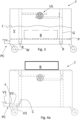
- Fig. 1 shows a support bench T comprising a work surface P and an operationally underlying, lower-closed container volume V, capable of containing a liquid, in particular an extinguishing and/or refrigerant liquid.
- the lower-closed volume is defined by an operationally horizontal back wall BW and by perimeter and operationally vertical walls LW.
- the support bench preferably has a parallelepiped shape, but could have different shapes depending on the circumstances.
- the work surface P is positioned at an ergonomic height between 90 and 110 cm as required by OHSAS 18001.
- the work surface is arranged to release, for example by rotating with respect to an edge hinged to a wall of the container volume, or to accompany the battery, by means of a translation.
- At least a portion of the work surface P is arranged to assume
- the work surface P is slidably associated with at least two perimeter and vertical walls LW by means of guides G, arranged to allow a transition between the first and second positions of the support surface, by translation.
- wheels R are rotatably fixed to the work surface P and are slidably associated with the vertical guides G, arranged on the internal faces of the perimeter and vertical walls LW to guide the support surface P during the stroke from the first to the second position and vice versa.
- Locking means UL are arranged to lock the work surface P in the first position.
- the locking devices can be manually and/or electrically released, for example, by means of an electric lock.
- the container volume closed at the bottom, includes hydraulic connection means PC which include for example a first manual valve V1, arranged externally to the container volume, and preferably quick coupling means for connection to a conduit connected to a source of refrigerant and/or extinguishing liquid L.
- hydraulic connection means PC which include for example a first manual valve V1, arranged externally to the container volume, and preferably quick coupling means for connection to a conduit connected to a source of refrigerant and/or extinguishing liquid L.
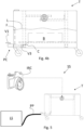
- a further preferred variant of the invention is shown, according to which the filling of the container volume V is performed automatically in response to the introduction of the load, i.e. the battery B, inside the same container volume.
- the hydraulic connection means comprise a second normally open valve V2 and a normally closed valve V3 in cascade to the second valve; both arranged inside the container volume.
- the battery When the battery is introduced into the container volume V, directly or indirectly, it acts on a lever operationally connected to the third normally closed valve V3 causing the opening of the third valve and therefore the flooding of the container volume V.
- the normally open valve V2 is associated with a float arranged in the container volume. When the extinguishing and/or refrigerant liquid L reaches a predetermined level, then the float closes the second valve V2.
- the filling of the container volume V is completely automated.
- the blocking means UL are electro-actuated and interlocked with a monitoring system.
- monitoring is performed 24 hours a day, without the presence of a human operator and furthermore, the immersion of the battery in the liquid is performed completely automatically with greater safety not only for people but also for the working environment.
- the support bench is equipped with wheels W fixed under the back wall BW to allow easy movement of the same even in the presence of liquid inside, defining a trolley.
- the device T When the device T is equipped with wheels W, then it defines a trolley.
- This trolley can be equipped with handles (not shown) to facilitate its grip and movement. Implementation variants to the non-limiting example described are possible, without however departing from the scope of protection of the present invention, including all the equivalent embodiments for a technician in the field, to the content of the claims.
Landscapes
- Engineering & Computer Science (AREA)
- Mechanical Engineering (AREA)
- Health & Medical Sciences (AREA)
- Public Health (AREA)
- Business, Economics & Management (AREA)
- Emergency Management (AREA)
- Battery Mounting, Suspending (AREA)
Abstract
Support bench or trolley (T) for the maintenance of a vehicle propulsion battery (B) comprising a work surface (P), a container volume (V) closed at the bottom arranged operationally underneath the work surface and capable of containing a refrigerant and/or extinguishing liquid (L) and locking means (UL) arranged to unlock the work surface; the work surface being capable of releasing or accompanying the battery inside the container volume (V).
Description
- The present invention relates to the field of support benches or trolleys for the maintenance of a vehicle propulsion battery.
- Battery packs used to propel electric vehicles store large amounts of energy in a small space, defining high energy densities.
- Individual cells or groups of cells can be equipped with devices that try to limit or avoid the effects of anomalous situations that can compromise safety. A typical phenomenon considered anomalous is the so-called thermal runaway. Phenomenon in which a large amount of heat and gases are developed that can lead to the ignition of a fire.
- Such conditions can be caused by the failure of a battery cell, thermal or mechanical abuse or the short circuit of at least one of the cells of the battery pack.
- The heat released by the short circuit can be quite large, depending on many factors, including the amount of energy converted into heat and the location of the short circuit, can start a chain reaction.
- When the temperature that develops exceeds a predetermined threshold which is approximately 200°C in relation to the electro-chemical characteristics of the cell, an irreversible exothermic chain reaction is triggered which causes the overheating and failure of the cells adjacent to the one initially damaged, releasing heat which, in turn, spreads to the entire battery pack.
- Depending on the characteristics of the individual cells and the configuration of the battery pack casing, a fire may start or, in extreme cases, the entire battery pack may explode.
- When the battery pack is disconnected from a related vehicle, the related control and monitoring systems are not able to signal the triggering of a thermal drift with serious risk for maintenance workers who are preparing to disassemble the battery pack.
- Unless specifically excluded in the detailed description that follows, what is described in this chapter is to be considered as an integral part of the detailed description.
- The purpose of the present invention is to make maintenance operations conducted on a vehicle battery pack safer.
- The basic idea of the present invention is to propose a support bench or trolley for the maintenance of a vehicle propulsion battery comprising a work surface and an underlying container volume capable of containing a coolant/extinguishing liquid, wherein the work surface is capable of releasing or accompanying a battery supports into the container volume in response to a detection of a dangerous condition.
- The dangerous situation can be determined by the operator and therefore the trolley comprises at least one human/machine interface device arranged to activate the immersion of the vehicle battery subject to maintenance. The dangerous situation can be determined by a special detection system configured to automatically activate the immersion of the vehicle battery being maintained.
- It should be noted that the terms "battery pack" and "battery" have the same meaning, meaning a set of cells packed inside a casing which may include electrical and electronic circuitry known in itself.
- According to a first preferred variant of the invention, the container volume of the trolley contains the coolant/extinguishing liquid before the vehicle battery is placed on the relative support surface for maintenance. According to a second preferred variant of the invention, the container volume of the trolley is empty, the trolley includes hydraulic means for connection to a coolant/extinguishing liquid pipeline and means are present for activating the filling of the container volume of the trolley. More preferably, the trolley includes means for automatically activating the filling of the container volume in response to the introduction of the battery inside the container volume.
- The dependent claims describe preferred variants of the invention, forming an integral part of this description.
- Further objects and advantages of the present invention will be clear from the following detailed description of an embodiment thereof (and variants thereof) and from the attached drawings given purely for explanatory and non-limiting purposes, in which:
-
Fig. 1 discloses schematically a first variant of a support bench according to the present invention; -
Fig. 2 discloses schematically a second variant of a trolley according to the present invention; -
Fig. 3 discloses schematically a third variant of a support bench according to the present invention; -
Figs. 4a - 4b disclose two configurations assumed by the variant of the invention according to the previous figures; -
Fig. 5 discloses a safety system for the maintenance of vehicle propulsion batteries. - The same reference numbers and letters in the figures identify the same elements or components or functions.
- It should also be noted that the terms "first", "second", "third", "upper", "lower" and the like may be used here to distinguish various elements. These terms do not imply a spatial, sequential or hierarchical order for the modified elements unless specifically indicated or inferred from the text.
- The elements and features illustrated in the various preferred embodiments, including the drawings, may be combined with each other without departing from the scope of protection of this application as described below.
- With the help of
Figs. 1 - 3 , some variants of the present invention are shown. -
Fig. 1 shows a support bench T comprising a work surface P and an operationally underlying, lower-closed container volume V, capable of containing a liquid, in particular an extinguishing and/or refrigerant liquid. - The lower-closed volume is defined by an operationally horizontal back wall BW and by perimeter and operationally vertical walls LW.
- The support bench preferably has a parallelepiped shape, but could have different shapes depending on the circumstances.
- Preferably, the work surface P is positioned at an ergonomic height between 90 and 110 cm as required by OHSAS 18001.
- The work surface is arranged to release, for example by rotating with respect to an edge hinged to a wall of the container volume, or to accompany the battery, by means of a translation.
- It is advantageous to exploit the weight force acting on the load itself to facilitate its introduction into the container volume.
- According to the present invention, at least a portion of the work surface P is arranged to assume
- A first support position, capable of supporting a load, and in particular a battery, externally to the container volume V;
- A second collapsed position, capable of allowing the load to enter the container volume V.
- More specifically, the work surface P is slidably associated with at least two perimeter and vertical walls LW by means of guides G, arranged to allow a transition between the first and second positions of the support surface, by translation. For this purpose, wheels R are rotatably fixed to the work surface P and are slidably associated with the vertical guides G, arranged on the internal faces of the perimeter and vertical walls LW to guide the support surface P during the stroke from the first to the second position and vice versa.
- Locking means UL are arranged to lock the work surface P in the first position.
- The locking devices can be manually and/or electrically released, for example, by means of an electric lock.
- When the UL locking means are deactivated to unlock the work surface, this is arranged to release the load which therefore falls inside the container volume.
- According to the variant of
figures 2 and3 , the container volume, closed at the bottom, includes hydraulic connection means PC which include for example a first manual valve V1, arranged externally to the container volume, and preferably quick coupling means for connection to a conduit connected to a source of refrigerant and/or extinguishing liquid L. So, when an operator detects a thermal drift, he/she can cause the work surface to be unlocked, by acting on the locking means, and subsequently open the valve V1 of the hydraulic connection so as to flood the container volume. The locking means can be made in any way, and act directly on the work surface P or indirectly on the wheels R. - With the help of
Figs 4a and4b , a further preferred variant of the invention is shown, according to which the filling of the container volume V is performed automatically in response to the introduction of the load, i.e. the battery B, inside the same container volume. According to this variant, the hydraulic connection means comprise a second normally open valve V2 and a normally closed valve V3 in cascade to the second valve; both arranged inside the container volume. - When the battery is introduced into the container volume V, directly or indirectly, it acts on a lever operationally connected to the third normally closed valve V3 causing the opening of the third valve and therefore the flooding of the container volume V. The normally open valve V2 is associated with a float arranged in the container volume. When the extinguishing and/or refrigerant liquid L reaches a predetermined level, then the float closes the second valve V2.
- From the comparison of
Figs. 4a and4b , it can be seen that the lowering of the work surface causes the third valve V3 to open, while the raising of the liquid level L causes the corresponding lifting of the float associated with the second valve V2 which therefore closes. - Advantageously, the filling of the container volume V is completely automated.
- According to a further preferred variant of the invention, the blocking means UL are electro-actuated and interlocked with a monitoring system.
- A safety system SS according to the present invention comprises
- the detection system IRC of a thermal runaway of the battery, preferably comprising a thermal camera arranged to monitor the load supported by the work surface and
- the bench or trolley T described above,
- Advantageously, monitoring is performed 24 hours a day, without the presence of a human operator and furthermore, the immersion of the battery in the liquid is performed completely automatically with greater safety not only for people but also for the working environment.
- Preferably, the support bench is equipped with wheels W fixed under the back wall BW to allow easy movement of the same even in the presence of liquid inside, defining a trolley.
- When the device T is equipped with wheels W, then it defines a trolley. This trolley can be equipped with handles (not shown) to facilitate its grip and movement. Implementation variants to the non-limiting example described are possible, without however departing from the scope of protection of the present invention, including all the equivalent embodiments for a technician in the field, to the content of the claims.
- From the description reported above, the technician in the field is able to realize the object of the invention without introducing further construction details.
Claims (9)
- Support bench or trolley (T) for the maintenance of a vehicle propulsion battery (B) comprising- a work surface (P),- a container volume (V), closed at the bottom, operatively arranged under the work surface and capable of containing a refrigerant and/or extinguishing liquid (L) and- locking means (UL) arranged to unlock the work surface, the work surface being capable of releasing or accompanying the battery inside the container volume (V) in response to a deactivation of the lock means.
- Bench or trolley according to claim 1, wherein said container volume comprises hydraulic connection means (PC) for connection to a duct (PP) connected to a source (LS) of refrigerant and/or extinguishing liquid (L).
- Bench or trolley according to claim 2, wherein said hydraulic connection means comprise means for quick coupling to the duct (PP) connected to the source (LS).
- A bench or trolley according to claim 2 or 3, comprising second control means (C) for causing a flooding of the container volume in response to the release or accompaniment of the battery (B) into the container volume.
- A bench or trolley according to claim 4, comprising a second valve (V2), normally open, and a third valve (V3) normally closed in cascade to the second valve, wherein the second and third valves are arranged internally to the container volume, wherein the second valve comprises first control means (F) for causing a closure of the second valve in response to the reaching of a predetermined level of liquid inside the container volume, and wherein said third valve comprises said second control means (C) for causing an opening of the third valve in response to a contact with the battery (B) released or accompaniment into the container volume.
- A bench or trolley according to any of the preceding claims 1 - 5, wherein said work surface is hinged to a wall of the container volume.
- A bench or trolley according to any of the preceding claims 1 - 5, wherein said work surface is slidably associated with two opposing walls of the container volume to translate inside the container volume.
- A bench or trolley according to any of the preceding claims 1 - 7, wherein said locking means are manually operable and/or by means of an electro-actuator.
- Safety system comprising:- a detection system (IRC) of a thermal runaway of a vehicle propulsion battery, for monitoring the battery (B) supported by a work surface (P),- the bench or trolley (T) according to any of the preceding claims 1 - 7 when said locking means are operable by means of an electro-actuator,wherein said work surface belongs to said bench or trolley and wherein the detection system is configured to deactivate the lock means, in response to a detection of a possible thermal runaway of the battery.
Applications Claiming Priority (1)
| Application Number | Priority Date | Filing Date | Title |
|---|---|---|---|
| IT102023000010992A IT202300010992A1 (en) | 2023-05-30 | 2023-05-30 | Support bench or trolley for the maintenance of a vehicle propulsion battery |
Publications (1)
| Publication Number | Publication Date |
|---|---|
| EP4470724A1 true EP4470724A1 (en) | 2024-12-04 |
Family
ID=87889188
Family Applications (1)
| Application Number | Title | Priority Date | Filing Date |
|---|---|---|---|
| EP24179151.6A Pending EP4470724A1 (en) | 2023-05-30 | 2024-05-30 | Support workbench or trolley for the maintenance of a vehicular propulsion battery |
Country Status (2)
| Country | Link |
|---|---|
| EP (1) | EP4470724A1 (en) |
| IT (1) | IT202300010992A1 (en) |
Citations (4)
| Publication number | Priority date | Publication date | Assignee | Title |
|---|---|---|---|---|
| EP2929987A1 (en) * | 2014-04-08 | 2015-10-14 | Peugeot Citroën Automobiles Sa | Workbench for electrochemical batteries, comprising a water tray arranged below same |
| WO2022085992A1 (en) * | 2020-10-19 | 2022-04-28 | 퍼스트 유한회사 | System for extinguishing fire in battery loading container in electric propulsion ship |
| CN114504749A (en) * | 2022-01-25 | 2022-05-17 | 国网安徽省电力有限公司电力科学研究院 | Energy storage battery detection test bench |
| KR20230070958A (en) * | 2021-11-15 | 2023-05-23 | 주식회사 어스앤배터리 | Electric Vehicle Battery Test Bed System With Fire Suppression Function |
-
2023
- 2023-05-30 IT IT102023000010992A patent/IT202300010992A1/en unknown
-
2024
- 2024-05-30 EP EP24179151.6A patent/EP4470724A1/en active Pending
Patent Citations (4)
| Publication number | Priority date | Publication date | Assignee | Title |
|---|---|---|---|---|
| EP2929987A1 (en) * | 2014-04-08 | 2015-10-14 | Peugeot Citroën Automobiles Sa | Workbench for electrochemical batteries, comprising a water tray arranged below same |
| WO2022085992A1 (en) * | 2020-10-19 | 2022-04-28 | 퍼스트 유한회사 | System for extinguishing fire in battery loading container in electric propulsion ship |
| KR20230070958A (en) * | 2021-11-15 | 2023-05-23 | 주식회사 어스앤배터리 | Electric Vehicle Battery Test Bed System With Fire Suppression Function |
| CN114504749A (en) * | 2022-01-25 | 2022-05-17 | 国网安徽省电力有限公司电力科学研究院 | Energy storage battery detection test bench |
Also Published As
| Publication number | Publication date |
|---|---|
| IT202300010992A1 (en) | 2024-11-30 |
Similar Documents
| Publication | Publication Date | Title |
|---|---|---|
| CN107681085B (en) | Battery replacement station, battery warehouse and control method for battery pack storage device in battery replacement station | |
| JP6321638B2 (en) | Nuclear power plant, safety system including fuse device, and fuse device | |
| EP2650251B1 (en) | Forklift truck | |
| JP2015524559A5 (en) | ||
| CN108597633A (en) | The shielding conveyer method and equipment of spentnuclear fuel | |
| JP2023129349A (en) | block stacking device | |
| FI12774Y1 (en) | Storage container for batteries | |
| CN118999984A (en) | Electric automobile power battery package operating mode testing arrangement | |
| JP7426855B2 (en) | Battery stand | |
| CN213364182U (en) | A shaking table test specimen evacuation system | |
| CN214825935U (en) | Isolation boxes for transporting vehicles with power batteries | |
| KR102835722B1 (en) | Immersion tank for recyling secondary battery discharge work | |
| IT202300010992A1 (en) | Support bench or trolley for the maintenance of a vehicle propulsion battery | |
| EP4239775A2 (en) | A container system arranged for storing and/or transporting a rechargeable battery and a method of storing and/or transporting the rechargeable battery | |
| EP3708754A1 (en) | Vehicle equipped with a thermal runaway safety system | |
| WO2021213645A1 (en) | An electric energy storage system for a vehicle | |
| WO2019020110A1 (en) | Charging stand, abnormal charging determination and processing method and system, power converter station, and energy storage station | |
| CN214454070U (en) | Stacker with fire-fighting station | |
| WO2025262585A1 (en) | Fire safety system for parking areas, method and related parking area | |
| KR20240086471A (en) | Fire extinguishing system for electric vehicl charging facility | |
| EP4675768A1 (en) | A liquid reservoir for thermal runaway management | |
| CN118025626B (en) | Battery logistics pallets and their management system | |
| CN222400058U (en) | Double-station workbin cargo bed for battery library | |
| CN218867296U (en) | Explosion-proof battery box | |
| CN220544729U (en) | Abnormal battery transition processing device |
Legal Events
| Date | Code | Title | Description |
|---|---|---|---|
| PUAI | Public reference made under article 153(3) epc to a published international application that has entered the european phase |
Free format text: ORIGINAL CODE: 0009012 |
|
| STAA | Information on the status of an ep patent application or granted ep patent |
Free format text: STATUS: THE APPLICATION HAS BEEN PUBLISHED |
|
| AK | Designated contracting states |
Kind code of ref document: A1 Designated state(s): AL AT BE BG CH CY CZ DE DK EE ES FI FR GB GR HR HU IE IS IT LI LT LU LV MC ME MK MT NL NO PL PT RO RS SE SI SK SM TR |
|
| STAA | Information on the status of an ep patent application or granted ep patent |
Free format text: STATUS: REQUEST FOR EXAMINATION WAS MADE |
|
| 17P | Request for examination filed |
Effective date: 20250506 |