EP4470694A1 - Systems and methods for producing cold sprayed components with coatings thereon - Google Patents
Systems and methods for producing cold sprayed components with coatings thereon Download PDFInfo
- Publication number
- EP4470694A1 EP4470694A1 EP24174401.0A EP24174401A EP4470694A1 EP 4470694 A1 EP4470694 A1 EP 4470694A1 EP 24174401 A EP24174401 A EP 24174401A EP 4470694 A1 EP4470694 A1 EP 4470694A1
- Authority
- EP
- European Patent Office
- Prior art keywords
- layer
- component
- coating layer
- mold
- initial
- Prior art date
- Legal status (The legal status is an assumption and is not a legal conclusion. Google has not performed a legal analysis and makes no representation as to the accuracy of the status listed.)
- Pending
Links
Images




Classifications
-
- B—PERFORMING OPERATIONS; TRANSPORTING
- B22—CASTING; POWDER METALLURGY
- B22F—WORKING METALLIC POWDER; MANUFACTURE OF ARTICLES FROM METALLIC POWDER; MAKING METALLIC POWDER; APPARATUS OR DEVICES SPECIALLY ADAPTED FOR METALLIC POWDER
- B22F10/00—Additive manufacturing of workpieces or articles from metallic powder
- B22F10/20—Direct sintering or melting
- B22F10/25—Direct deposition of metal particles, e.g. direct metal deposition [DMD] or laser engineered net shaping [LENS]
-
- B—PERFORMING OPERATIONS; TRANSPORTING
- B22—CASTING; POWDER METALLURGY
- B22F—WORKING METALLIC POWDER; MANUFACTURE OF ARTICLES FROM METALLIC POWDER; MAKING METALLIC POWDER; APPARATUS OR DEVICES SPECIALLY ADAPTED FOR METALLIC POWDER
- B22F10/00—Additive manufacturing of workpieces or articles from metallic powder
- B22F10/40—Structures for supporting workpieces or articles during manufacture and removed afterwards
- B22F10/43—Structures for supporting workpieces or articles during manufacture and removed afterwards characterised by material
-
- B—PERFORMING OPERATIONS; TRANSPORTING
- B22—CASTING; POWDER METALLURGY
- B22F—WORKING METALLIC POWDER; MANUFACTURE OF ARTICLES FROM METALLIC POWDER; MAKING METALLIC POWDER; APPARATUS OR DEVICES SPECIALLY ADAPTED FOR METALLIC POWDER
- B22F10/00—Additive manufacturing of workpieces or articles from metallic powder
- B22F10/60—Treatment of workpieces or articles after build-up
- B22F10/62—Treatment of workpieces or articles after build-up by chemical means
-
- B—PERFORMING OPERATIONS; TRANSPORTING
- B22—CASTING; POWDER METALLURGY
- B22F—WORKING METALLIC POWDER; MANUFACTURE OF ARTICLES FROM METALLIC POWDER; MAKING METALLIC POWDER; APPARATUS OR DEVICES SPECIALLY ADAPTED FOR METALLIC POWDER
- B22F10/00—Additive manufacturing of workpieces or articles from metallic powder
- B22F10/60—Treatment of workpieces or articles after build-up
- B22F10/64—Treatment of workpieces or articles after build-up by thermal means
-
- B—PERFORMING OPERATIONS; TRANSPORTING
- B22—CASTING; POWDER METALLURGY
- B22F—WORKING METALLIC POWDER; MANUFACTURE OF ARTICLES FROM METALLIC POWDER; MAKING METALLIC POWDER; APPARATUS OR DEVICES SPECIALLY ADAPTED FOR METALLIC POWDER
- B22F7/00—Manufacture of composite layers, workpieces, or articles, comprising metallic powder, by sintering the powder, with or without compacting wherein at least one part is obtained by sintering or compression
- B22F7/06—Manufacture of composite layers, workpieces, or articles, comprising metallic powder, by sintering the powder, with or without compacting wherein at least one part is obtained by sintering or compression of composite workpieces or articles from parts, e.g. to form tipped tools
- B22F7/08—Manufacture of composite layers, workpieces, or articles, comprising metallic powder, by sintering the powder, with or without compacting wherein at least one part is obtained by sintering or compression of composite workpieces or articles from parts, e.g. to form tipped tools with one or more parts not made from powder
-
- B—PERFORMING OPERATIONS; TRANSPORTING
- B33—ADDITIVE MANUFACTURING TECHNOLOGY
- B33Y—ADDITIVE MANUFACTURING, i.e. MANUFACTURING OF THREE-DIMENSIONAL [3D] OBJECTS BY ADDITIVE DEPOSITION, ADDITIVE AGGLOMERATION OR ADDITIVE LAYERING, e.g. BY 3D PRINTING, STEREOLITHOGRAPHY OR SELECTIVE LASER SINTERING
- B33Y10/00—Processes of additive manufacturing
-
- B—PERFORMING OPERATIONS; TRANSPORTING
- B33—ADDITIVE MANUFACTURING TECHNOLOGY
- B33Y—ADDITIVE MANUFACTURING, i.e. MANUFACTURING OF THREE-DIMENSIONAL [3D] OBJECTS BY ADDITIVE DEPOSITION, ADDITIVE AGGLOMERATION OR ADDITIVE LAYERING, e.g. BY 3D PRINTING, STEREOLITHOGRAPHY OR SELECTIVE LASER SINTERING
- B33Y30/00—Apparatus for additive manufacturing; Details thereof or accessories therefor
-
- B—PERFORMING OPERATIONS; TRANSPORTING
- B33—ADDITIVE MANUFACTURING TECHNOLOGY
- B33Y—ADDITIVE MANUFACTURING, i.e. MANUFACTURING OF THREE-DIMENSIONAL [3D] OBJECTS BY ADDITIVE DEPOSITION, ADDITIVE AGGLOMERATION OR ADDITIVE LAYERING, e.g. BY 3D PRINTING, STEREOLITHOGRAPHY OR SELECTIVE LASER SINTERING
- B33Y40/00—Auxiliary operations or equipment, e.g. for material handling
- B33Y40/20—Post-treatment, e.g. curing, coating or polishing
-
- C—CHEMISTRY; METALLURGY
- C23—COATING METALLIC MATERIAL; COATING MATERIAL WITH METALLIC MATERIAL; CHEMICAL SURFACE TREATMENT; DIFFUSION TREATMENT OF METALLIC MATERIAL; COATING BY VACUUM EVAPORATION, BY SPUTTERING, BY ION IMPLANTATION OR BY CHEMICAL VAPOUR DEPOSITION, IN GENERAL; INHIBITING CORROSION OF METALLIC MATERIAL OR INCRUSTATION IN GENERAL
- C23C—COATING METALLIC MATERIAL; COATING MATERIAL WITH METALLIC MATERIAL; SURFACE TREATMENT OF METALLIC MATERIAL BY DIFFUSION INTO THE SURFACE, BY CHEMICAL CONVERSION OR SUBSTITUTION; COATING BY VACUUM EVAPORATION, BY SPUTTERING, BY ION IMPLANTATION OR BY CHEMICAL VAPOUR DEPOSITION, IN GENERAL
- C23C24/00—Coating starting from inorganic powder
- C23C24/02—Coating starting from inorganic powder by application of pressure only
- C23C24/04—Impact or kinetic deposition of particles
-
- C—CHEMISTRY; METALLURGY
- C23—COATING METALLIC MATERIAL; COATING MATERIAL WITH METALLIC MATERIAL; CHEMICAL SURFACE TREATMENT; DIFFUSION TREATMENT OF METALLIC MATERIAL; COATING BY VACUUM EVAPORATION, BY SPUTTERING, BY ION IMPLANTATION OR BY CHEMICAL VAPOUR DEPOSITION, IN GENERAL; INHIBITING CORROSION OF METALLIC MATERIAL OR INCRUSTATION IN GENERAL
- C23C—COATING METALLIC MATERIAL; COATING MATERIAL WITH METALLIC MATERIAL; SURFACE TREATMENT OF METALLIC MATERIAL BY DIFFUSION INTO THE SURFACE, BY CHEMICAL CONVERSION OR SUBSTITUTION; COATING BY VACUUM EVAPORATION, BY SPUTTERING, BY ION IMPLANTATION OR BY CHEMICAL VAPOUR DEPOSITION, IN GENERAL
- C23C28/00—Coating for obtaining at least two superposed coatings either by methods not provided for in a single one of groups C23C2/00 - C23C26/00 or by combinations of methods provided for in subclasses C23C and C25C or C25D
- C23C28/30—Coatings combining at least one metallic layer and at least one inorganic non-metallic layer
- C23C28/32—Coatings combining at least one metallic layer and at least one inorganic non-metallic layer including at least one pure metallic layer
- C23C28/321—Coatings combining at least one metallic layer and at least one inorganic non-metallic layer including at least one pure metallic layer with at least one metal alloy layer
-
- C—CHEMISTRY; METALLURGY
- C23—COATING METALLIC MATERIAL; COATING MATERIAL WITH METALLIC MATERIAL; CHEMICAL SURFACE TREATMENT; DIFFUSION TREATMENT OF METALLIC MATERIAL; COATING BY VACUUM EVAPORATION, BY SPUTTERING, BY ION IMPLANTATION OR BY CHEMICAL VAPOUR DEPOSITION, IN GENERAL; INHIBITING CORROSION OF METALLIC MATERIAL OR INCRUSTATION IN GENERAL
- C23C—COATING METALLIC MATERIAL; COATING MATERIAL WITH METALLIC MATERIAL; SURFACE TREATMENT OF METALLIC MATERIAL BY DIFFUSION INTO THE SURFACE, BY CHEMICAL CONVERSION OR SUBSTITUTION; COATING BY VACUUM EVAPORATION, BY SPUTTERING, BY ION IMPLANTATION OR BY CHEMICAL VAPOUR DEPOSITION, IN GENERAL
- C23C28/00—Coating for obtaining at least two superposed coatings either by methods not provided for in a single one of groups C23C2/00 - C23C26/00 or by combinations of methods provided for in subclasses C23C and C25C or C25D
- C23C28/30—Coatings combining at least one metallic layer and at least one inorganic non-metallic layer
- C23C28/34—Coatings combining at least one metallic layer and at least one inorganic non-metallic layer including at least one inorganic non-metallic material layer, e.g. metal carbide, nitride, boride, silicide layer and their mixtures, enamels, phosphates and sulphates
-
- C—CHEMISTRY; METALLURGY
- C25—ELECTROLYTIC OR ELECTROPHORETIC PROCESSES; APPARATUS THEREFOR
- C25D—PROCESSES FOR THE ELECTROLYTIC OR ELECTROPHORETIC PRODUCTION OF COATINGS; ELECTROFORMING; APPARATUS THEREFOR
- C25D7/00—Electroplating characterised by the article coated
- C25D7/04—Tubes; Rings; Hollow bodies
Definitions
- the present invention generally relates to coating processes, and more particularly relates to a method of forming a coating layer on a cold sprayed component.
- Performance enhancing coatings are often formed on surfaces of components by electrochemical plating processes.
- Electrochemical plating also known as electroplating, are processes that involves forming a metal coating on a conductive surface using an electrical current.
- Performance enhancing coatings applied by electrochemical plating processes may provide, for example, improved corrosion resistance, wear resistance, or thermal resistance.
- a method includes forming an initial layer on a mold, forming a coating layer on the initial layer, forming a component layer on the coating layer by a cold spraying additive manufacturing process, wherein contact surfaces between the component layer and the coating layer form a bond in situ, separating the initial layer from the mold, and removing the initial layer from the coating layer, wherein the component layer defines a component and the coating layer defines a coating thereon.
- a system includes a mold including interior surfaces that define a mold cavity, a first deposition apparatus configured to form an initial layer on the interior surfaces of the mold, a second deposition apparatus configured to form a coating layer on the initial layer, a cold spraying additive manufacturing apparatus configured to form a component layer on the coating layer such that contact surfaces between the component layer and the coating layer form a bond in situ, a component removal apparatus configured to separate the initial layer from the mold, and a layer removal apparatus configured to remove the initial layer from the coating layer, wherein the component layer defines a component and the coating layer defines a coating thereon.
- Systems and methods disclosed herein provide for forming one or more coating layers on surfaces of components.
- the systems and methods are particularly suitable for overcoming challenges associated with forming coating layers on naturally passivating materials via electrochemical plating processes.
- the systems and methods include forming at least one coating layer within a mold, and then forming the component on the coating layer by a cold spraying additive manufacturing process (also referred to as a cold spraying process).
- a cold spraying additive manufacturing process also referred to as a cold spraying process
- the coating layer(s) may be formed by an electrochemical plating process, and therefore, may provide various benefits of the electrochemical plating process while simultaneously avoiding or reducing certain challenges associated therewith, as described in more detail herein.
- FIG. 1 presents an exemplary method 100 for producing a component having a coating thereon.
- FIGS. 2-7 represent nonlimiting examples of various stages of the method 100. Specifically, FIGS. 2-4 represent various steps in forming certain layers of the component, FIGS. 5-6 represents various steps in removing the component from the mold and/or removing certain layers from the component, and FIG. 7 represents an isolated view of a resulting component produced by the method 100.
- layers produced by the method 100 will be referred to hereinafter by reference numbers shown in FIGS. 2-7 ; however, it should be understood that the various stages and layers represented in FIGS. 2-7 are merely exemplary and the method 100 is not limited thereto.
- the method 100 may start at 110.
- the method 100 may include providing a mold 210.
- the mold 210 may have a mold cavity having various shapes and sizes.
- the mold 210 may have a mold cavity that is configured to produce a substantially tubular component having, for example, a circular cross-section or faceted cross-section (e.g., rectangular, hexagonal, octagonal, etc.).
- the mold 210 may be formed of various materials.
- the mold 210 (or exposed surfaces within the mold cavity) may be formed of a material having a relatively low coefficient of thermal expansion (CTE), for example, below 5.0 ⁇ 10 -6 K -1 , such as below 2.0 ⁇ 10 -6 K -1 , such as below 1.0 ⁇ 10 -6 K -1 .
- the mold 210 may be formed of a nickel-iron alloy, such as Invar (FeNise).
- the method 100 may include forming an initial layer 212 on the mold 210, as represented in FIG. 2 .
- the initial layer 212 may be a sacrificial or release layer configured to promote removal of the component from the mold 210 upon completion of the production of the component.
- the initial layer 212 may be configured to promote a smooth surface texture of a subsequently form layer.
- the initial layer 212 may be configured to promote ease of removal thereof from underlying layers (e.g., a coating layer 214 discussed below)
- the initial layer 212 may be formed by various processes including, but not limited to, certain electrochemical plating processes, electroless plating processes, vacuum deposition processes (e.g., evaporation, sputtering, etc.), chemical vapor deposition processes, and thermal spraying processes.
- the initial layer 212 may be formed of various materials selected based on the intended function(s) of the initial layer 212 (e.g., releasability from the mold 210, surface roughness of a subsequent layer, removability from a subsequent layer, etc.).
- the initial layer 212 may be formed of a material having a high CTE relative to the mold 210 (or exposed surfaces within the mold cavity) to promote release of the initial layer 212 therefrom.
- the initial layer 212 may be formed of a material that may be selectively etched. In some embodiments, the initial layer 212 may be formed of a metallic material, such as copper, copper alloys, zinc, or zinc alloys. In some embodiments, the initial layer 212 may be formed of a material having a low melting temperature relative to the mold 210 and other layers of the component. In some embodiments, the initial layer 212 may be formed of a tin-lead (Sn/Pb) alloy. In some embodiments, the initial layer 212 may be formed of a natural or synthetic wax material.
- the method 100 may include forming a coating layer 214 on the initial layer 212, as represented in FIG. 3 .
- the coating layer 214 may be a performance enhancing layer configured to modify one or more operational properties of the component.
- the coating layer 214 may be configured to promote corrosion resistance, wear resistance, oxidation resistance, thermal resistance, and/or structural integrity of exterior surface of the component.
- the coating layer 214 may be formed by various processes including, but not limited to, certain electrochemical plating processes, electroless plating processes, vacuum deposition processes (e.g., evaporation, sputtering, etc.), chemical vapor deposition processes, and thermal spraying processes.
- the coating layer 214 may be formed of various materials selected based on the intended functionality thereof (e.g., wear resistance, corrosion resistance, thermal resistance, etc.).
- the coating layer 214 may be formed of a metallic material, such as nickel, nickel alloys, chromium, chromium alloys, cobalt, or cobalt alloys.
- the coating layer 214 may be formed of a nickel-tungsten alloy, a nickel-phosphorus alloy, a cobalt-phosphorus alloy, or a cobalt-nickel alloy. In some embodiments, the coating layer 214 may be formed of a ceramic material, such as certain oxides, carbides, or nitrides. In some embodiments, the coating layer 214 has a thickness of between about 50 micrometers ( ⁇ m) and 500 ⁇ m, such as about 250 ⁇ m to 500 ⁇ m, such as greater than 500 ⁇ m.
- the method 100 may include forming a component layer 216 on the coating layer 214 by a cold spraying additive manufacturing process, as represented in FIG. 4 .
- the component layer 216 may include the bulk of the component, for example, defining greater than 90 weight percent (wt.%) of the component, such as greater than 95 wt.%, such as greater than 98 wt.%.
- the cold spraying process may include various steps.
- the cold spraying process involves depositing material onto the coating layer 214 (or a layer therebetween) by accelerating powder particles to supersonic speeds using a high-pressure gas.
- the cold spraying process may include providing a powder material having to a particle size suitable for cold spraying.
- the powder material may be treated with a surfactant or other additives to improve various properties thereof such as flow and/or adhesion properties.
- a high-pressure gas such as nitrogen or helium, may be compressed to an operating pressure (e.g., several hundred bar) and heated to an operating temperature (e.g., several hundred degrees Celsius).
- the gas may be directed as a stream through a nozzle assembly (e.g., a converging-diverging nozzle) which accelerates the gas and produces a low-pressure region at an outlet of the nozzle assembly.
- the powdered material may be injected into the stream of the gas wherein the powder material is accelerated and heated by the gas.
- the powder material is heated to a temperature below a melting point thereof (i.e., the powder material does not melt).
- the powder material within the stream of the gas is directed by the nozzle assembly to impact and adhere to the coating layer 214 (or a layer therebetween).
- the nozzle assembly and/or the mold 210 may be moved while spraying the powder material to form a dense and cohesive coating.
- the above-described process may be repeated to build up a desired shape or structure of the component layer-by-layer.
- contact surfaces between the component layer 216 and the coating layer 214 (or a layer therebetween) form a bond in situ.
- the operating parameters of the cold spraying process may vary depending, for example, on the materials used and the desired shape and/or structure of the component. Nonlimiting examples of cold spraying processes and parameters thereof are disclosed in U.S. Patent No. 11,415,380 to Chipko et al., incorporated herein by reference in its entirety, that may be suitable for some embodiments herein.
- the component layer 216 may be formed of various materials.
- the component layer 216 is formed of a metallic materials such as titanium, titanium alloys, aluminum, aluminum alloys, magnesium, or magnesium alloys.
- the component layer 216 is formed of a non-equilibrium alloy (e.g., AA2009).
- a non-equilibrium alloy refers to an alloy that is not in thermodynamic equilibrium at room temperature and atmospheric pressure, and has a non-uniform distribution of atoms or molecules. These alloys may be produced using rapid solidification techniques, such as quenching or rapid cooling from a molten state, which prevent the material from reaching an equilibrium state and result in a metastable microstructure.
- Nonlimiting examples of non-equilibrium alloys include metallic glasses, which are alloys with an amorphous (non-crystalline) structure, and nanocrystalline alloys, which have a fine-grained structure with grain sizes in the nanometer range.
- the method 100 may include separating the initial layer 212 from the mold 210.
- the initial layer 212 may be removed from the mold 210 by various methods.
- the method 100 may include removing the initial layer 212 from the coating layer 214.
- the initial layer 212 may be removed from the coating layer 214 by various methods.
- separating the initial layer 212 from the mold 210 (at 120), and removing the initial layer 212 from the coating layer 214 (at 122) may be performed separately.
- the initial layer 212 may be present on the coating layer 214 subsequent to separation of the initial layer 212 from the mold 210, as represented in FIG. 5 .
- separating the initial layer 212 from the mold 210 may be performed by a mechanical release process wherein a force is applied to the component relative to the mold 210 that is sufficient to cause separation due to mechanical failure of the initial layer 212, or performed by a thermal cycling process wherein a temperature of the mold 210 and/or component is increased or decreased in a manner that causes separation due to a mismatch of CTE between the mold 210 and the initial layer 212 (or other layers).
- the initial coating may then be removed from the coating layer 214 by, for example, a selective etching process wherein an etchant is applied to selectively remove the initial layer 212 while preserving the coating layer 214 and the component layer 216 or a melting process wherein a temperature of the initial layer 212 is increased above a melting point thereof such that the initial layer 212 melts and flows from the exposed surfaces of the mold cavity.
- a selective etching process wherein an etchant is applied to selectively remove the initial layer 212 while preserving the coating layer 214 and the component layer 216 or a melting process wherein a temperature of the initial layer 212 is increased above a melting point thereof such that the initial layer 212 melts and flows from the exposed surfaces of the mold cavity.
- nitric acid e.g., concentration of 50 wt.% may be applied to selectively etch a layer of copper or alloy thereof while preserving an underlying layer of aluminum or alloy thereof(e.g., alloy AA8009).
- separating the initial layer 212 from the mold 210 (at 120), and removing the initial layer 212 from the coating layer 214 (at 122) may be performed simultaneously.
- removing the initial layer 212 from the mold 210 and removing the initial layer 212 from the coating layer 214 may be performed simultaneously within the mold cavity by a selective etching process or a melting process, wherein the initial layer 212 is selectively removed from between the mold 210 and the coating layer 214, as represented in FIG. 6 .
- the steps of forming the component layer 216 (at 118), separating the initial layer 212 (at 120), and removing the initial layer 212 (at 122) are performed at temperatures below a crystallization temperature of the non-equilibrium alloy.
- separating the initial layer 212 from the coating layer 214 results in the coating layer 214 having a relatively smooth surface roughness, such as having an arithmetic average (Ra) of surface heights measured across the surface thereof of less than 0.254 micrometers (mm), such as between about 0.0254 mm and 0.254 mm.
- Ra arithmetic average
- separating the initial layer 212 from the coating layer 214 results in a final component defined by the component layer 216, the coating layer 214, and optionally, any layers therebetween. In some embodiments, separating the initial layer 212 from the coating layer 214 results in an intermediate component defined by the component layer 216, the coating layer 214, and optionally, any layers therebetween, and various post-processing steps may be performed on the intermediate component to produce a final component.
- the method 100 may end at 124.
- the method 100 may be used to produce various components having various shapes, structures, and compositions.
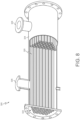
- FIGS. 8 and 9 represent an application wherein the method 100 is used to produce components of a heat exchanger 300.
- an array of tubes 320 is joined to header structure 322.
- the header structure 322 assumes the form of a manifold plate or tube sheet.
- the heat exchanger 300 is a shell-and-tube heat exchange and includes a shell 324 having an inlet 326 and an outlet 328 through which a liquid or gaseous coolant may be conducted during heat exchanger operation.
- the temperature-regulated fluid is conducted from header structure 322, through array of tubes 320, and to another header structure (hidden from view in FIG. 8 ) before discharge from the heat exchanger 300.
- Heat is thus removed from the temperature-regulated fluid, thermally conducted through the walls of individual tubes in the array of tubes 320, and ultimately transferred to the coolant fluid circulated through shell 324 and impinging upon the exteriors of the individual tubes forming array of tubes 320.
- other types of fluid can be circulated through the heat exchanger 300 or the above-described thermal transfer relationship can be reversed such that the temperature-regulated fluid is heated as the fluid passes through heat exchanger 300.
- FIG. 9 presents an isolated cross-sectional view of a portion of one of the individual tubes of the array of tubes 320.
- the tube includes a component layer 316 having a coating layer 314 formed thereon, for example, by the method 100.
- the system 400 includes a mold 410 having interior surfaces that define a mold cavity, a first deposition apparatus 412 configured to form an initial layer on the interior surfaces of the mold 410, a second deposition apparatus 414 configured to form a coating layer on the initial layer, a cold spray additive manufacturing apparatus configured to form a component layer on the coating layer via a cold spraying process, a first apparatus 418 configured to remove the initial layer from the interior surfaces of the mold 410, and a second apparatus configured to remove the initial layer from the coating layer.
- the first deposition apparatus 412 and/or the second apparatus device 414 may be configured to perform electrochemical plating processes, electroless plating processes, vacuum deposition processes (e.g., evaporation, sputtering, etc.), chemical vapor deposition processes, and thermal spraying processes.
- the first deposition apparatus 412 and the second deposition apparatus 414 may be a single deposition apparatus.
- the cold spraying additive manufacturing apparatus 416 may be any cold spraying apparatus capable of forming the component layer on the coating layer via a cold spraying process as described herein.
- the first apparatus 418 may be any apparatus capable of removing the initial layer from the interior surfaces of the mold 410. In various embodiments, the first apparatus 418 may be any apparatus configured to perform a mechanical release process wherein a force is applied to the component relative to the mold 410 that is sufficient to cause separation due to mechanical failure of the initial layer. In various embodiments, the first apparatus 418 may be any apparatus configured to perform a thermal cycling process wherein a temperature of the mold 410 is increased or decreased in a manner that causes separation due to a mismatch of CTE between the mold 410 and the initial layer.
- the first apparatus 418 may be any apparatus configured to perform an etching process wherein an etchant is applied to selectively remove the initial layer while preserving the coating layer and the component layer.
- the first apparatus 418 may be any apparatus configured to perform a melting process wherein a temperature of the initial layer is increased above a melting point thereof such that the initial layer melts and flows from the exposed surfaces of the mold cavity.
- the second apparatus 420 may be any apparatus capable of removing the initial layer from the coating layer. In various embodiments, the second apparatus 420 may be any apparatus configured to perform an etching process wherein an etchant is applied to selectively remove the initial layer while preserving the coating layer and the component layer. In various embodiments, the second apparatus 420 may be any apparatus configured to perform a melting process wherein a temperature of the initial layer is increased above a melting point thereof such that the initial layer melts and flows from the coating layer. In various embodiments, the first apparatus 418 and the second apparatus 420 may be a single apparatus.
- the systems and methods disclosed herein provide various benefits over certain existing systems and methods. For example, it can be quite challenging to obtain a strong interlayer bond and to achieve a smooth exterior surface on the resulting coating when working with workpieces formed of certain materials, such as those that naturally passivate easily.
- the systems and methods disclosed herein address these issues by forming a coating layer within a mold and then forming a component layer on the coating layer by a cold spraying additive manufacturing process. In this manner, contact surfaces between the component layer and the coating layer form a bond in situ and the coating layer has a relatively smooth exterior surface.
- the systems and methods disclosed herein form the initial layer 212 on the mold 210 and the coating layer 214 on the initial layer 212.
- the final exterior layer of the coating layer 214 will be influenced by the mold 210 and can be relatively smooth (e.g., Ra of less than 0.254 micrometers).
- the surfaces of the coating layer 214 in contact with the component layer 216 have a surface roughness dictated by the electrochemical plating process, and therefore are relatively rough (e.g., Ra of greater than 0.254 micrometers). This rough interior surface of the coating layer 214 promotes adhesion with the cold sprayed component layer 216.
- the term “substantially” denotes within 5% to account for manufacturing tolerances. Also, as used herein, the term “about” denotes within 5% to account for manufacturing tolerances.
Landscapes
- Chemical & Material Sciences (AREA)
- Engineering & Computer Science (AREA)
- Materials Engineering (AREA)
- Manufacturing & Machinery (AREA)
- Chemical Kinetics & Catalysis (AREA)
- Metallurgy (AREA)
- Organic Chemistry (AREA)
- Mechanical Engineering (AREA)
- Inorganic Chemistry (AREA)
- General Chemical & Material Sciences (AREA)
- Electrochemistry (AREA)
- Physics & Mathematics (AREA)
- Thermal Sciences (AREA)
- Composite Materials (AREA)
- Other Surface Treatments For Metallic Materials (AREA)
Abstract
Description
- The present invention generally relates to coating processes, and more particularly relates to a method of forming a coating layer on a cold sprayed component.
- Performance enhancing coatings are often formed on surfaces of components by electrochemical plating processes. Electrochemical plating, also known as electroplating, are processes that involves forming a metal coating on a conductive surface using an electrical current. Performance enhancing coatings applied by electrochemical plating processes may provide, for example, improved corrosion resistance, wear resistance, or thermal resistance.
- However, certain materials, such as those that naturally passivate readily, can be difficult to coat by electrochemical plating processes. For example, aluminum naturally forms an oxide layer thereon that may interfere with the electrochemical plating process. In particular, it can be quite challenging to obtain a strong bond between the aluminum surface and the coating layer, and to achieve a smooth exterior surface on the resulting coating.
- Hence, there is a need for methods of coating components, such as those that passivate readily, that are capable of providing strong interlayer bonds. Furthermore, other desirable features and characteristics of the present invention will become apparent from the subsequent detailed description and the appended claims, taken in conjunction with the accompanying drawings and the foregoing technical field and background.
- This summary is provided to describe select concepts in a simplified form that are further described in the Detailed Description. This summary is not intended to identify key or essential features of the claimed subject matter, nor is it intended to be used as an aid in determining the scope of the claimed subject matter.
- A method is provided that includes forming an initial layer on a mold, forming a coating layer on the initial layer, forming a component layer on the coating layer by a cold spraying additive manufacturing process, wherein contact surfaces between the component layer and the coating layer form a bond in situ, separating the initial layer from the mold, and removing the initial layer from the coating layer, wherein the component layer defines a component and the coating layer defines a coating thereon.
- A system is provided that includes a mold including interior surfaces that define a mold cavity, a first deposition apparatus configured to form an initial layer on the interior surfaces of the mold, a second deposition apparatus configured to form a coating layer on the initial layer, a cold spraying additive manufacturing apparatus configured to form a component layer on the coating layer such that contact surfaces between the component layer and the coating layer form a bond in situ, a component removal apparatus configured to separate the initial layer from the mold, and a layer removal apparatus configured to remove the initial layer from the coating layer, wherein the component layer defines a component and the coating layer defines a coating thereon.
- Furthermore, other desirable features and characteristics of the system and method will become apparent from the subsequent detailed description and the appended claims, taken in conjunction with the accompanying drawings and the preceding background.
- The present disclosure will hereinafter be described in conjunction with the following drawing figures, wherein like numerals denote like elements, and wherein:
-
FIG. 1 is a flowchart illustrating an exemplary method for producing a component with a coating layer thereon in accordance with an embodiment; -
FIGS. 2-7 schematically represent layers formed at various steps of the method ofFIG. 1 in accordance with various embodiments; -
FIG. 8 schematically represents a perspective view a heat exchanger with a cut-away portion showing an array of tubes in accordance with an embodiment; -
FIG. 9 schematically represents a cross-sectional view of an individual tube of the heat exchanger ofFIG. 8 produced by the method ofFIG. 1 in accordance with an embodiment; and -
FIG. 10 is a block diagram that schematically represents a system for producing a component with a coating layer thereon in accordance with an embodiment. - The following detailed description is merely exemplary in nature and is not intended to limit the invention or the application and uses of the invention. As used herein, the word "exemplary" means "serving as an example, instance, or illustration." Thus, any embodiment described herein as "exemplary" is not necessarily to be construed as preferred or advantageous over other embodiments. All of the embodiments described herein are exemplary embodiments provided to enable persons skilled in the art to make or use the invention and not to limit the scope of the invention which is defined by the claims. Furthermore, there is no intention to be bound by any expressed or implied theory presented in the preceding technical field, background, brief summary, or the following detailed description.
- Systems and methods disclosed herein provide for forming one or more coating layers on surfaces of components. The systems and methods are particularly suitable for overcoming challenges associated with forming coating layers on naturally passivating materials via electrochemical plating processes. In general, the systems and methods include forming at least one coating layer within a mold, and then forming the component on the coating layer by a cold spraying additive manufacturing process (also referred to as a cold spraying process). Although not required, in some embodiments, the coating layer(s) may be formed by an electrochemical plating process, and therefore, may provide various benefits of the electrochemical plating process while simultaneously avoiding or reducing certain challenges associated therewith, as described in more detail herein.
-
FIG. 1 presents anexemplary method 100 for producing a component having a coating thereon.FIGS. 2-7 represent nonlimiting examples of various stages of themethod 100. Specifically,FIGS. 2-4 represent various steps in forming certain layers of the component,FIGS. 5-6 represents various steps in removing the component from the mold and/or removing certain layers from the component, andFIG. 7 represents an isolated view of a resulting component produced by themethod 100. For convenience, layers produced by themethod 100 will be referred to hereinafter by reference numbers shown inFIGS. 2-7 ; however, it should be understood that the various stages and layers represented inFIGS. 2-7 are merely exemplary and themethod 100 is not limited thereto. - Referring initially to
FIG. 1 , themethod 100 may start at 110. At 112, themethod 100 may include providing amold 210. Themold 210 may have a mold cavity having various shapes and sizes. In some embodiments, themold 210 may have a mold cavity that is configured to produce a substantially tubular component having, for example, a circular cross-section or faceted cross-section (e.g., rectangular, hexagonal, octagonal, etc.). Themold 210 may be formed of various materials. In some embodiments, the mold 210 (or exposed surfaces within the mold cavity) may be formed of a material having a relatively low coefficient of thermal expansion (CTE), for example, below 5.0 ×10⁻⁶K-1, such as below 2.0 ×10⁻⁶K-1, such as below 1.0 ×10⁻⁶K-1. In some embodiments, themold 210 may be formed of a nickel-iron alloy, such as Invar (FeNise). - At 114, the
method 100 may include forming aninitial layer 212 on themold 210, as represented inFIG. 2 . In various embodiments, theinitial layer 212 may be a sacrificial or release layer configured to promote removal of the component from themold 210 upon completion of the production of the component. In some embodiments, theinitial layer 212 may be configured to promote a smooth surface texture of a subsequently form layer. In some embodiments, theinitial layer 212 may be configured to promote ease of removal thereof from underlying layers (e.g., acoating layer 214 discussed below) - The
initial layer 212 may be formed by various processes including, but not limited to, certain electrochemical plating processes, electroless plating processes, vacuum deposition processes (e.g., evaporation, sputtering, etc.), chemical vapor deposition processes, and thermal spraying processes. Theinitial layer 212 may be formed of various materials selected based on the intended function(s) of the initial layer 212 (e.g., releasability from themold 210, surface roughness of a subsequent layer, removability from a subsequent layer, etc.). In some embodiments, theinitial layer 212 may be formed of a material having a high CTE relative to the mold 210 (or exposed surfaces within the mold cavity) to promote release of theinitial layer 212 therefrom. In some embodiments, theinitial layer 212 may be formed of a material that may be selectively etched. In some embodiments, theinitial layer 212 may be formed of a metallic material, such as copper, copper alloys, zinc, or zinc alloys. In some embodiments, theinitial layer 212 may be formed of a material having a low melting temperature relative to themold 210 and other layers of the component. In some embodiments, theinitial layer 212 may be formed of a tin-lead (Sn/Pb) alloy. In some embodiments, theinitial layer 212 may be formed of a natural or synthetic wax material. - At 116, the
method 100 may include forming acoating layer 214 on theinitial layer 212, as represented inFIG. 3 . In various embodiments, thecoating layer 214 may be a performance enhancing layer configured to modify one or more operational properties of the component. In some embodiments, thecoating layer 214 may be configured to promote corrosion resistance, wear resistance, oxidation resistance, thermal resistance, and/or structural integrity of exterior surface of the component. - The
coating layer 214 may be formed by various processes including, but not limited to, certain electrochemical plating processes, electroless plating processes, vacuum deposition processes (e.g., evaporation, sputtering, etc.), chemical vapor deposition processes, and thermal spraying processes. Thecoating layer 214 may be formed of various materials selected based on the intended functionality thereof (e.g., wear resistance, corrosion resistance, thermal resistance, etc.). In some embodiments, thecoating layer 214 may be formed of a metallic material, such as nickel, nickel alloys, chromium, chromium alloys, cobalt, or cobalt alloys. In some embodiments, thecoating layer 214 may be formed of a nickel-tungsten alloy, a nickel-phosphorus alloy, a cobalt-phosphorus alloy, or a cobalt-nickel alloy. In some embodiments, thecoating layer 214 may be formed of a ceramic material, such as certain oxides, carbides, or nitrides. In some embodiments, thecoating layer 214 has a thickness of between about 50 micrometers (µm) and 500 µm, such as about 250 µm to 500 µm, such as greater than 500 µm. - At 118, the
method 100 may include forming acomponent layer 216 on thecoating layer 214 by a cold spraying additive manufacturing process, as represented inFIG. 4 . In some embodiments, thecomponent layer 216 may include the bulk of the component, for example, defining greater than 90 weight percent (wt.%) of the component, such as greater than 95 wt.%, such as greater than 98 wt.%. - The cold spraying process may include various steps. In some embodiments, the cold spraying process involves depositing material onto the coating layer 214 (or a layer therebetween) by accelerating powder particles to supersonic speeds using a high-pressure gas. More specifically, the cold spraying process may include providing a powder material having to a particle size suitable for cold spraying. Optionally, the powder material may be treated with a surfactant or other additives to improve various properties thereof such as flow and/or adhesion properties. A high-pressure gas, such as nitrogen or helium, may be compressed to an operating pressure (e.g., several hundred bar) and heated to an operating temperature (e.g., several hundred degrees Celsius). The gas may be directed as a stream through a nozzle assembly (e.g., a converging-diverging nozzle) which accelerates the gas and produces a low-pressure region at an outlet of the nozzle assembly. The powdered material may be injected into the stream of the gas wherein the powder material is accelerated and heated by the gas. In various embodiments, the powder material is heated to a temperature below a melting point thereof (i.e., the powder material does not melt).
- The powder material within the stream of the gas is directed by the nozzle assembly to impact and adhere to the coating layer 214 (or a layer therebetween). The nozzle assembly and/or the
mold 210 may be moved while spraying the powder material to form a dense and cohesive coating. The above-described process may be repeated to build up a desired shape or structure of the component layer-by-layer. In various embodiments, contact surfaces between thecomponent layer 216 and the coating layer 214 (or a layer therebetween) form a bond in situ. The operating parameters of the cold spraying process may vary depending, for example, on the materials used and the desired shape and/or structure of the component. Nonlimiting examples of cold spraying processes and parameters thereof are disclosed inU.S. Patent No. 11,415,380 - The
component layer 216 may be formed of various materials. In some embodiments, thecomponent layer 216 is formed of a metallic materials such as titanium, titanium alloys, aluminum, aluminum alloys, magnesium, or magnesium alloys. In some embodiments, thecomponent layer 216 is formed of a non-equilibrium alloy (e.g., AA2009). As used herein, a non-equilibrium alloy refers to an alloy that is not in thermodynamic equilibrium at room temperature and atmospheric pressure, and has a non-uniform distribution of atoms or molecules. These alloys may be produced using rapid solidification techniques, such as quenching or rapid cooling from a molten state, which prevent the material from reaching an equilibrium state and result in a metastable microstructure. Nonlimiting examples of non-equilibrium alloys include metallic glasses, which are alloys with an amorphous (non-crystalline) structure, and nanocrystalline alloys, which have a fine-grained structure with grain sizes in the nanometer range. - At 120, the
method 100 may include separating theinitial layer 212 from themold 210. Theinitial layer 212 may be removed from themold 210 by various methods. At 122, themethod 100 may include removing theinitial layer 212 from thecoating layer 214. Theinitial layer 212 may be removed from thecoating layer 214 by various methods. - In some embodiments, separating the
initial layer 212 from the mold 210 (at 120), and removing theinitial layer 212 from the coating layer 214 (at 122) may be performed separately. In such embodiments, theinitial layer 212 may be present on thecoating layer 214 subsequent to separation of theinitial layer 212 from themold 210, as represented inFIG. 5 . As nonlimiting examples, separating theinitial layer 212 from themold 210 may be performed by a mechanical release process wherein a force is applied to the component relative to themold 210 that is sufficient to cause separation due to mechanical failure of theinitial layer 212, or performed by a thermal cycling process wherein a temperature of themold 210 and/or component is increased or decreased in a manner that causes separation due to a mismatch of CTE between themold 210 and the initial layer 212 (or other layers). - The initial coating may then be removed from the
coating layer 214 by, for example, a selective etching process wherein an etchant is applied to selectively remove theinitial layer 212 while preserving thecoating layer 214 and thecomponent layer 216 or a melting process wherein a temperature of theinitial layer 212 is increased above a melting point thereof such that theinitial layer 212 melts and flows from the exposed surfaces of the mold cavity. As a first nonlimiting example, nitric acid (e.g., concentration of 50 wt.%) may be applied to selectively etch a layer of copper or alloy thereof while preserving an underlying layer of aluminum or alloy thereof(e.g., alloy AA8009). As other nonlimiting examples, ammoniacal ammonium chloride may be applied to selectively etch a layer of copper or alloy thereof while preserving an underlying layer of nickel or alloy thereof, cobalt or alloy thereof, or chrome or alloy thereof. - In some embodiments, separating the
initial layer 212 from the mold 210 (at 120), and removing theinitial layer 212 from the coating layer 214 (at 122) may be performed simultaneously. As nonlimiting examples, removing theinitial layer 212 from themold 210 and removing theinitial layer 212 from thecoating layer 214 may be performed simultaneously within the mold cavity by a selective etching process or a melting process, wherein theinitial layer 212 is selectively removed from between themold 210 and thecoating layer 214, as represented inFIG. 6 . - For embodiments in which the
component layer 216 includes a non-equilibrium alloy, the steps of forming the component layer 216 (at 118), separating the initial layer 212 (at 120), and removing the initial layer 212 (at 122) are performed at temperatures below a crystallization temperature of the non-equilibrium alloy. - In some embodiments, separating the
initial layer 212 from thecoating layer 214 results in thecoating layer 214 having a relatively smooth surface roughness, such as having an arithmetic average (Ra) of surface heights measured across the surface thereof of less than 0.254 micrometers (mm), such as between about 0.0254 mm and 0.254 mm. - In some embodiments, separating the
initial layer 212 from thecoating layer 214 results in a final component defined by thecomponent layer 216, thecoating layer 214, and optionally, any layers therebetween. In some embodiments, separating theinitial layer 212 from thecoating layer 214 results in an intermediate component defined by thecomponent layer 216, thecoating layer 214, and optionally, any layers therebetween, and various post-processing steps may be performed on the intermediate component to produce a final component. Themethod 100 may end at 124. - The
method 100 may be used to produce various components having various shapes, structures, and compositions. As a specific but nonlimiting example,FIGS. 8 and9 represent an application wherein themethod 100 is used to produce components of aheat exchanger 300. Referring toFIG. 8 , an array oftubes 320 is joined toheader structure 322. In this particular example, theheader structure 322 assumes the form of a manifold plate or tube sheet. In this particular example, theheat exchanger 300 is a shell-and-tube heat exchange and includes ashell 324 having aninlet 326 and anoutlet 328 through which a liquid or gaseous coolant may be conducted during heat exchanger operation. Concurrently, the temperature-regulated fluid is conducted fromheader structure 322, through array oftubes 320, and to another header structure (hidden from view inFIG. 8 ) before discharge from theheat exchanger 300. Heat is thus removed from the temperature-regulated fluid, thermally conducted through the walls of individual tubes in the array oftubes 320, and ultimately transferred to the coolant fluid circulated throughshell 324 and impinging upon the exteriors of the individual tubes forming array oftubes 320. In alternative embodiments, other types of fluid can be circulated through theheat exchanger 300 or the above-described thermal transfer relationship can be reversed such that the temperature-regulated fluid is heated as the fluid passes throughheat exchanger 300.FIG. 9 presents an isolated cross-sectional view of a portion of one of the individual tubes of the array oftubes 320. In this example, the tube includes acomponent layer 316 having acoating layer 314 formed thereon, for example, by themethod 100. - Referring to
FIG. 10 , a block diagram is presented that schematically represents asystem 400 configured to produce a component having a coating thereon, for example, by themethod 100. Thesystem 400 includes amold 410 having interior surfaces that define a mold cavity, afirst deposition apparatus 412 configured to form an initial layer on the interior surfaces of themold 410, asecond deposition apparatus 414 configured to form a coating layer on the initial layer, a cold spray additive manufacturing apparatus configured to form a component layer on the coating layer via a cold spraying process, afirst apparatus 418 configured to remove the initial layer from the interior surfaces of themold 410, and a second apparatus configured to remove the initial layer from the coating layer. - In various embodiments, the
first deposition apparatus 412 and/or thesecond apparatus device 414 may be configured to perform electrochemical plating processes, electroless plating processes, vacuum deposition processes (e.g., evaporation, sputtering, etc.), chemical vapor deposition processes, and thermal spraying processes. In various embodiments, thefirst deposition apparatus 412 and thesecond deposition apparatus 414 may be a single deposition apparatus. - The cold spraying
additive manufacturing apparatus 416 may be any cold spraying apparatus capable of forming the component layer on the coating layer via a cold spraying process as described herein. - In various embodiments, the
first apparatus 418 may be any apparatus capable of removing the initial layer from the interior surfaces of themold 410. In various embodiments, thefirst apparatus 418 may be any apparatus configured to perform a mechanical release process wherein a force is applied to the component relative to themold 410 that is sufficient to cause separation due to mechanical failure of the initial layer. In various embodiments, thefirst apparatus 418 may be any apparatus configured to perform a thermal cycling process wherein a temperature of themold 410 is increased or decreased in a manner that causes separation due to a mismatch of CTE between themold 410 and the initial layer. In various embodiments, thefirst apparatus 418 may be any apparatus configured to perform an etching process wherein an etchant is applied to selectively remove the initial layer while preserving the coating layer and the component layer. In various embodiments, thefirst apparatus 418 may be any apparatus configured to perform a melting process wherein a temperature of the initial layer is increased above a melting point thereof such that the initial layer melts and flows from the exposed surfaces of the mold cavity. - In various embodiments, the
second apparatus 420 may be any apparatus capable of removing the initial layer from the coating layer. In various embodiments, thesecond apparatus 420 may be any apparatus configured to perform an etching process wherein an etchant is applied to selectively remove the initial layer while preserving the coating layer and the component layer. In various embodiments, thesecond apparatus 420 may be any apparatus configured to perform a melting process wherein a temperature of the initial layer is increased above a melting point thereof such that the initial layer melts and flows from the coating layer. In various embodiments, thefirst apparatus 418 and thesecond apparatus 420 may be a single apparatus. - The systems and methods disclosed herein provide various benefits over certain existing systems and methods. For example, it can be quite challenging to obtain a strong interlayer bond and to achieve a smooth exterior surface on the resulting coating when working with workpieces formed of certain materials, such as those that naturally passivate easily. The systems and methods disclosed herein address these issues by forming a coating layer within a mold and then forming a component layer on the coating layer by a cold spraying additive manufacturing process. In this manner, contact surfaces between the component layer and the coating layer form a bond in situ and the coating layer has a relatively smooth exterior surface.
- In addition, for layers deposited via electrochemical plating processes, surface roughness increases with increasing layer thickness. Typically, this requires a post-processing process, such as a grinding process, to be performs to obtain a relatively smooth surface. The systems and methods disclosed herein form the
initial layer 212 on themold 210 and thecoating layer 214 on theinitial layer 212. As such, the final exterior layer of thecoating layer 214 will be influenced by themold 210 and can be relatively smooth (e.g., Ra of less than 0.254 micrometers). Further, the surfaces of thecoating layer 214 in contact with thecomponent layer 216 have a surface roughness dictated by the electrochemical plating process, and therefore are relatively rough (e.g., Ra of greater than 0.254 micrometers). This rough interior surface of thecoating layer 214 promotes adhesion with the cold sprayedcomponent layer 216. - In this document, relational terms such as first and second, and the like may be used solely to distinguish one entity or action from another entity or action without necessarily requiring or implying any actual such relationship or order between such entities or actions. Numerical ordinals such as "first," "second," "third," etc. simply denote different singles of a plurality and do not imply any order or sequence unless specifically defined by the claim language. The sequence of the text in any of the claims does not imply that process steps must be performed in a temporal or logical order according to such sequence unless it is specifically defined by the language of the claim. The process steps may be interchanged in any order without departing from the scope of the invention as long as such an interchange does not contradict the claim language and is not logically nonsensical.
- As used herein, the term "substantially" denotes within 5% to account for manufacturing tolerances. Also, as used herein, the term "about" denotes within 5% to account for manufacturing tolerances.
- While at least one exemplary embodiment has been presented in the foregoing detailed description of the invention, it should be appreciated that a vast number of variations exist. It should also be appreciated that the exemplary embodiment or exemplary embodiments are only examples, and are not intended to limit the scope, applicability, or configuration of the invention in any way. Rather, the foregoing detailed description will provide those skilled in the art with a convenient road map for implementing an exemplary embodiment of the invention. It being understood that various changes may be made in the function and arrangement of elements described in an exemplary embodiment without departing from the scope of the invention as set forth in the appended claims.
Claims (10)
- A method, comprising:forming an initial layer on a mold;forming a coating layer on the initial layer;forming a component layer on the coating layer by a cold spraying additive manufacturing process, wherein contact surfaces between the component layer and the coating layer form a bond in situ;separating the initial layer from the mold; andremoving the initial layer from the coating layer, wherein the component layer defines a component and the coating layer defines a coating thereon.
- The method of claim 1, wherein:separating the initial layer from the mold is performed by a mechanical release process, and removing the initial layer from the coating layer is performed by a selective etching process or a melting process;separating the initial layer from the mold is performed by a thermal cycling process, and removing the initial layer from the coating layer is performed by a selective etching process or a melting process;separating the initial layer from the mold and removing the initial layer from the coating layer are simultaneously performed by a selective etching process; orseparating the initial layer from the mold and removing the initial layer from the coating layer are simultaneously performed by a melting process.
- The method of claim 1, wherein removing the initial layer from the coating layer results in a surface of the coating layer having an arithmetic average (Ra) of surface heights measured across the surface of less than 0.254 micrometers.
- The method of claim 1, wherein the initial layer is copper or an alloy thereof, wherein the coating layer is nickel or alloy thereof, cobalt or alloy thereof, a carbide, or a nitride, wherein the component layer is titanium, aluminum, magnesium, or alloys thereof.
- The method of claim 1, wherein the component layer is a non-equilibrium alloy, wherein forming the component layer, separating the initial layer from the mold, and removing the initial layer from the coating layer are performed at temperatures below a crystallization temperature of the non-equilibrium alloy.
- A system, comprising:a mold including interior surfaces that define a mold cavity;a first deposition apparatus configured to form an initial layer on the interior surfaces of the mold;a second deposition apparatus configured to form a coating layer on the initial layer;a cold spraying additive manufacturing apparatus configured to form a component layer on the coating layer such that contact surfaces between the component layer and the coating layer form a bond in situ;a component removal apparatus configured to separate the initial layer from the mold; anda layer removal apparatus configured to remove the initial layer from the coating layer, wherein the component layer defines a component and the coating layer defines a coating thereon.
- The system of claim 6, wherein:the component removal apparatus is configured to perform a mechanical release process, and the layer removal apparatus is configured to perform a selective etching process or a melting process;the component removal apparatus is configured to perform a thermal cycling process, and the layer removal apparatus is configured to perform a selective etching process or a melting process;the component removal apparatus and the layer removal apparatus are defined by a single selective etching apparatus configured to perform a selective etching process within the mold; orthe component removal apparatus and the layer removal apparatus are defined by a single heat treatment apparatus configured to perform a melting process within the mold.
- The system of claim 6, wherein the layer removal apparatus is configured to provide a surface of the coating layer with an arithmetic average (Ra) of surface heights measured across the surface of less than 0.254 micrometers.
- The system of claim 6, wherein the initial layer is copper or an alloy thereof, wherein the coating layer is nickel or alloy thereof, cobalt or alloy thereof, a carbide, or a nitride, wherein the component layer is titanium, aluminum, magnesium, or alloys thereof.
- The system of claim 6, wherein the component layer is a non-equilibrium alloy and the cold spraying additive manufacturing apparatus, the component removal apparatus, and the layer removal apparatus are each configured to operate at temperatures below a crystallization temperature of the non-equilibrium alloy.
Applications Claiming Priority (1)
| Application Number | Priority Date | Filing Date | Title |
|---|---|---|---|
| US18/325,774 US20240399458A1 (en) | 2023-05-30 | 2023-05-30 | Systems and methods for producing cold sprayed components with coatings thereon |
Publications (1)
| Publication Number | Publication Date |
|---|---|
| EP4470694A1 true EP4470694A1 (en) | 2024-12-04 |
Family
ID=91027252
Family Applications (1)
| Application Number | Title | Priority Date | Filing Date |
|---|---|---|---|
| EP24174401.0A Pending EP4470694A1 (en) | 2023-05-30 | 2024-05-06 | Systems and methods for producing cold sprayed components with coatings thereon |
Country Status (2)
| Country | Link |
|---|---|
| US (1) | US20240399458A1 (en) |
| EP (1) | EP4470694A1 (en) |
Citations (6)
| Publication number | Priority date | Publication date | Assignee | Title |
|---|---|---|---|---|
| DE102009048706A1 (en) * | 2009-10-08 | 2011-04-28 | Hermle Maschinenbau Gmbh | Method and device for producing a molded part by means of generative application |
| DE102011100123A1 (en) * | 2011-04-26 | 2012-10-31 | Faurecia Innenraum Systeme Gmbh | Producing molded shells in metal spraying- or metal injecting process, comprises applying sacrificial layer on milling model, applying metal layer, and removing sacrificial layer and separating metal layer from milling model |
| US20170022615A1 (en) * | 2014-03-31 | 2017-01-26 | Siemens Aktiengesellschaft | Method For Producing A Hollow Body By Cold Spraying And Mould Core Suitable For Carrying Out Said Method |
| US20170144225A1 (en) * | 2013-01-24 | 2017-05-25 | California Institute Of Technology | Systems and methods for fabricating objects including amorphous metal using techniques akin to additive manufacturing |
| US20180179641A1 (en) * | 2016-12-22 | 2018-06-28 | United Technologies Corporation | Multi-wall deposited thin sheet structure |
| US11415380B2 (en) | 2018-01-29 | 2022-08-16 | Honeywell International Inc. | Heat exchangers, heat exchanger tubes, and additive manufacturing cold spray processes for producing the same |
Family Cites Families (6)
| Publication number | Priority date | Publication date | Assignee | Title |
|---|---|---|---|---|
| US8561668B2 (en) * | 2011-07-28 | 2013-10-22 | United Technologies Corporation | Rapid manufacturing method |
| US20150124401A1 (en) * | 2012-05-04 | 2015-05-07 | Christopher D. Prest | Consumer electronics port having bulk amorphous alloy core and a ductile cladding |
| US8584732B1 (en) * | 2012-09-24 | 2013-11-19 | The United States Of America As Represented By The Secretary Of The Army | Mold release method for a cold spray process |
| US10648084B2 (en) * | 2016-12-22 | 2020-05-12 | United Technologies Corporation | Material deposition to form a sheet structure |
| US20210156043A1 (en) * | 2019-11-25 | 2021-05-27 | The Boeing Company | Method for plating a metallic material onto a titanium substrate |
| EP4355933A4 (en) * | 2021-06-18 | 2026-01-07 | Maxterial Inc | COATED SURFACES, COATINGS AND ITEMS WITH IT |
-
2023
- 2023-05-30 US US18/325,774 patent/US20240399458A1/en active Pending
-
2024
- 2024-05-06 EP EP24174401.0A patent/EP4470694A1/en active Pending
Patent Citations (6)
| Publication number | Priority date | Publication date | Assignee | Title |
|---|---|---|---|---|
| DE102009048706A1 (en) * | 2009-10-08 | 2011-04-28 | Hermle Maschinenbau Gmbh | Method and device for producing a molded part by means of generative application |
| DE102011100123A1 (en) * | 2011-04-26 | 2012-10-31 | Faurecia Innenraum Systeme Gmbh | Producing molded shells in metal spraying- or metal injecting process, comprises applying sacrificial layer on milling model, applying metal layer, and removing sacrificial layer and separating metal layer from milling model |
| US20170144225A1 (en) * | 2013-01-24 | 2017-05-25 | California Institute Of Technology | Systems and methods for fabricating objects including amorphous metal using techniques akin to additive manufacturing |
| US20170022615A1 (en) * | 2014-03-31 | 2017-01-26 | Siemens Aktiengesellschaft | Method For Producing A Hollow Body By Cold Spraying And Mould Core Suitable For Carrying Out Said Method |
| US20180179641A1 (en) * | 2016-12-22 | 2018-06-28 | United Technologies Corporation | Multi-wall deposited thin sheet structure |
| US11415380B2 (en) | 2018-01-29 | 2022-08-16 | Honeywell International Inc. | Heat exchangers, heat exchanger tubes, and additive manufacturing cold spray processes for producing the same |
Non-Patent Citations (2)
| Title |
|---|
| NIKBAKHT R ET AL: "The role of deposition sequence in cold spraying of dissimilar materials", SURFACE AND COATINGS TECHNOLOGY, vol. 367, 27 March 2019 (2019-03-27), pages 75 - 85, XP085663236, ISSN: 0257-8972, DOI: 10.1016/J.SURFCOAT.2019.03.065 * |
| ZOU YU: "Cold Spray Additive Manufacturing: Microstructure Evolution and Bonding Features", ACCOUNTS OF MATERIALS RESEARCH, vol. 2, no. 11, 12 October 2021 (2021-10-12), pages 1071 - 1081, XP055951492, ISSN: 2643-6728, DOI: 10.1021/accountsmr.1c00138 * |
Also Published As
| Publication number | Publication date |
|---|---|
| US20240399458A1 (en) | 2024-12-05 |
Similar Documents
| Publication | Publication Date | Title |
|---|---|---|
| US11415380B2 (en) | Heat exchangers, heat exchanger tubes, and additive manufacturing cold spray processes for producing the same | |
| KR101247410B1 (en) | Metallic glass laminate, process for producing the same and use thereof | |
| US20060166020A1 (en) | High strength amorphous and microcrystaline structures and coatings | |
| US6043451A (en) | Plasma spraying of nickel-titanium compound | |
| JP4108152B2 (en) | Fluid cooling product having protective film and method for producing the same | |
| US9579718B2 (en) | Systems and methods for fabricating objects including amorphous metal using techniques akin to additive manufacturing | |
| EP3008227B1 (en) | Corrosion resistant hydrophobic coatings and methods of production thereof | |
| US20060216428A1 (en) | Applying bond coat to engine components using cold spray | |
| US20120171041A1 (en) | Thin-walled structural component, and method for the production thereof | |
| JPH09509985A (en) | Oriented ultrafine grain sputtering target and method of manufacturing the same | |
| CA2686242A1 (en) | Fine grained, non banded, refractory metal sputtering targets with a uniformly random crystallographic orientation, method for making such film, and thin film based devices and products made there from | |
| JPH05504172A (en) | Plasma spraying of rapidly solidifying aluminum-based alloys | |
| US20150197858A1 (en) | Fabrication of three-dimensional heat transfer enhancing features on a substrate | |
| US6134785A (en) | Method of fabricating an article of manufacture such as a heat exchanger | |
| JP3946226B2 (en) | Metal glass laminate and method for producing the same | |
| JP3194268B2 (en) | Equally reduced fine grain hardened surface | |
| JP4644653B2 (en) | Metal glass laminate | |
| US20240399458A1 (en) | Systems and methods for producing cold sprayed components with coatings thereon | |
| Salimijazi et al. | Study of solidification behavior and splat morphology of vacuum plasma sprayed Ti alloy by computational modeling and experimental results | |
| US7332123B2 (en) | Method for manufacturing composite articles and the articles obtained therefrom | |
| Hammouda et al. | Magnetic Performance and Microstructural Characterization of Cold Sprayed Ferromagnetic Materials | |
| Gärtner et al. | Bonding Mechanisms and Applications of Cold Spraying | |
| JP4895561B2 (en) | Metal glass spray coating and method for forming the same | |
| JP4751260B2 (en) | Continuous casting mold and manufacturing method thereof | |
| CN117604513B (en) | A method and application for preparing high-strength aluminum alloy coatings under cold conditions by cold spraying. |
Legal Events
| Date | Code | Title | Description |
|---|---|---|---|
| PUAI | Public reference made under article 153(3) epc to a published international application that has entered the european phase |
Free format text: ORIGINAL CODE: 0009012 |
|
| STAA | Information on the status of an ep patent application or granted ep patent |
Free format text: STATUS: THE APPLICATION HAS BEEN PUBLISHED |
|
| AK | Designated contracting states |
Kind code of ref document: A1 Designated state(s): AL AT BE BG CH CY CZ DE DK EE ES FI FR GB GR HR HU IE IS IT LI LT LU LV MC ME MK MT NL NO PL PT RO RS SE SI SK SM TR |
|
| P01 | Opt-out of the competence of the unified patent court (upc) registered |
Free format text: CASE NUMBER: APP_8678/2025 Effective date: 20250220 |
|
| STAA | Information on the status of an ep patent application or granted ep patent |
Free format text: STATUS: REQUEST FOR EXAMINATION WAS MADE |
|
| 17P | Request for examination filed |
Effective date: 20250530 |