EP4470644A2 - Water amusement ride motion governor - Google Patents
Water amusement ride motion governor Download PDFInfo
- Publication number
- EP4470644A2 EP4470644A2 EP24206774.2A EP24206774A EP4470644A2 EP 4470644 A2 EP4470644 A2 EP 4470644A2 EP 24206774 A EP24206774 A EP 24206774A EP 4470644 A2 EP4470644 A2 EP 4470644A2
- Authority
- EP
- European Patent Office
- Prior art keywords
- support element
- ride vehicle
- ride
- flow path
- buoyant
- Prior art date
- Legal status (The legal status is an assumption and is not a legal conclusion. Google has not performed a legal analysis and makes no representation as to the accuracy of the status listed.)
- Pending
Links
Images





Classifications
-
- A—HUMAN NECESSITIES
- A63—SPORTS; GAMES; AMUSEMENTS
- A63G—MERRY-GO-ROUNDS; SWINGS; ROCKING-HORSES; CHUTES; SWITCHBACKS; SIMILAR DEVICES FOR PUBLIC AMUSEMENT
- A63G21/00—Chutes; Helter-skelters
- A63G21/18—Water-chutes
-
- A—HUMAN NECESSITIES
- A63—SPORTS; GAMES; AMUSEMENTS
- A63G—MERRY-GO-ROUNDS; SWINGS; ROCKING-HORSES; CHUTES; SWITCHBACKS; SIMILAR DEVICES FOR PUBLIC AMUSEMENT
- A63G31/00—Amusement arrangements
- A63G31/007—Amusement arrangements involving water
Definitions
- the present disclosure relates generally to the field of amusement parks. Specifically, embodiments of the present disclosure relate to techniques to govern motion of a ride vehicle of an attraction.
- amusement rides have been used for many years in amusement or theme parks. These amusement rides include water-based rides. Certain water-based rides include show elements, e.g., special effects or animatronic set pieces, at particular locations along a flow path. Generally, water-based rides attempt to align a start time of a show element with an arrival of a ride vehicle to the show element. Some water-based rides adjust a start time of the show element to ensure that the show element is initiated as the ride vehicle arrives. However, adjusting the start time of the show element may lead to inconsistent ride durations and, consequently, inconsistent ride queues. Other water-based rides attempt to adjust the speed of the ride vehicle, such that the ride vehicle arrives to the show element at a set start time for the show element. However, adjusting the speed and/or location of a water-based ride vehicle is complex, particular for water vehicles that are influenced by water current or gravity effects.
- a ride system in accordance with one embodiment, includes a flume providing a flow path of a water ride and configured to accommodate a buoyant ride vehicle.
- the ride system also includes at least one support element extending into the flow path and at least partially submerged within the flow path.
- the ride system includes a driving mechanism configured to actuate the at least one support element such that the at least one support element moves relative to the flow path in response to a control signal.
- the at least one support element is configured to contact the buoyant ride vehicle to control movement of the buoyant ride vehicle along the flow path while the at least one support element is being actuated.
- the ride system includes a controller configured to generate the control signal based at least in part on a location of the buoyant ride vehicle in the flow path and a timer controlling activation of a show element, wherein the show element is located along the flow path.
- a ride system in accordance with another embodiment, includes a motion governor.
- the motion governor includes a conveyor configured to rotate along a track disposed within a flow path of water ride.
- the motion governor also includes a driving mechanism configured to control rotation of the conveyor in response to a control signal.
- the motion governor includes at least one support element coupled to the conveyor. The at least one support element is configured to contact a ride vehicle to control movement of the ride vehicle along the flow path.
- the ride system also includes a controller configured to receive a location signal indicative of a location of the ride vehicle along the flow path, estimate an arrival time to a show element based on the location, determine that the estimated arrival time deviates from a scheduled show element start time, and generate the control signal upon determining that the estimated arrival time deviates from the scheduled show element start time.
- a method to govern motion of the ride vehicle along a flow path of the water-based ride attraction includes the step of providing a flow path configured to be traversed by a buoyant ride vehicle.
- the method also includes the step of receiving a control signal comprising instructions to actuate a driving mechanism based at least in part on a location of the buoyant ride vehicle in the flow path and a timer of a show element.
- the method also includes the step of actuating the driving mechanism in response to the control signal.
- At least one support element is coupled to the driving mechanism and configured to move along the flow path as a result of actuating the driving mechanism.
- the method also includes the step of contacting the ride vehicle with the at least one support element to change a speed of the ride vehicle along the flow path.
- a ride system in accordance with another embodiment, includes a controller configured to determine a location of a ride vehicle with respect to a show element. The controller is also configured to determine an estimated arrival of the buoyant ride vehicle at the show element based at least in part on the location. The controller is also configured to determine that the estimated arrival time deviates from a scheduled show element start time. The controller is also configured to generate a control signal comprising instructions to rotate a conveyor upon determining that the estimated arrival time deviates from the scheduled show element start time.
- the at least one support element is coupled to the conveyor and is configured to contact the buoyant ride vehicle to control movement of the ride vehicle along a flow path based on rotation of the conveyor.
- the controller is also configured to output the control signal to a motion governor coupled to the conveyor.
- Theme park or amusement park attractions have become increasingly popular, and various amusement park attractions have been created to provide passengers with unique motion and visual experiences.
- These theme park or amusement park attractions include water-based attractions.
- Water-based attractions may have at least one ride vehicle configured to carry passengers along a flow path.
- the attraction may also have one or more show elements, e.g., special effects, movable set pieces, distributed along the ride or flow path of the ride vehicle.
- buoyant water-ride vehicles are subject to variable forces such as water current, gravity, water levels, passenger weight. Accordingly, buoyant water ride vehicles operate with wider time slippage over the course of the ride and a greater variability in speed.
- the water-based attraction may dynamically adjust the start time of the show element.
- ride times which may in turn cause excess wait times for the ride.
- certain rides may include features that adjust the speed of the ride vehicle along the flow path using a track or other locking system that couples the ride vehicle to the flume to control advancement of the ride vehicle.
- a system or method for adjusting the speed of the ride vehicle e.g., to achieve alignment with one or more show elements, while maintaining the floating or buoyant effect experienced by a guest in the ride vehicle is provided.
- FIG. 1 is a schematic view of a water-based attraction 10 with a ride vehicle 12 traveling along a flow path 14 of the water-based attraction during a ride cycle.
- the ride vehicle 12 includes at least one ride seat 16 for a passenger of the ride vehicle 12.
- the passenger may sit in the at least one ride seat as the ride vehicle 12 floats along the flow path 14.
- the ride vehicle 12 floats along the flow path 14 within a flume 18 (i.e., a channel for water).
- the flow path 14 may be defined by the flume 18.
- water jets, propellers, or other suitable devices may alter the flow path 14 within the flume 18.
- a current of the water or fluid within the flow path 14 propels the ride vehicle 12 along the flow path 14 in a desired direction or axis of travel (e.g. along arrow 19).
- the water-based attraction 10 includes at least one show element 20 located along the flow path 14.
- the at least one show element 20 may include animatronics, videos, sound effects, light effects, motion effects, water effects, or any other special effect.
- the at least one show element 20 may have a start time and end time.
- a scheduled show element start time of the show element 20 is based at least in part on a show clock 22.
- the at least one show element 20 may start at regular or scheduled timed intervals that correspond with estimated arrival of individual ride vehicles 12 at the show element 20.
- the show element 20 starts according to pre-scheduled start times.
- the ride vehicle 12 may should arrive at the show element 20 at a predetermined time so that the passenger experiences the show element 20 without missing a beginning or end of the show element 20.
- Starting the show element 20 at regular intervals or according to prescheduled start times may promote ride throughput predictability as compared to a show element 20 having varying start times.
- the water-based attraction 10 has one or more motion governors 26 that may at least in part control movement of the ride vehicle 12 along the flow path 14 or along certain portions of the flow path 14.
- the motion governor 26 is configured to control motion of the ride vehicle 12 such that the ride vehicle 12 arrives at the show element 20 at the predetermined time or at the scheduled start time of the show element 20 so that the passenger may experience the show element 20 without missing a beginning or end of the effect.
- the one or more motion governors 26 may only be configured to control motion of the ride vehicle 12 when the ride vehicle is predicted to arrive before or after the predetermined time or at the scheduled start time of the show element 20.
- the show element 20 includes an introduction buffer configured to form an arrival window for the ride vehicle 12.
- the introduction buffer may include preliminary videos, sound effects, light effects, motion effects, water effects, or any other special effect.
- the introduction buffer may include a ten second window of music playing prior to the start of the show element 20.
- the one or more motion governors 26 are configured to control motion of the ride vehicle 12 such that the ride vehicle 12 arrives at the show element 20 during the arrival window. Further, in some embodiments, the one or more motion governors 26 may only be configured to control motion of the ride vehicle 12 when the ride vehicle 12 is predicted to arrive before or after the arrival window.
- the motion governor 26 operates in conjunction with the show element 20 and is configured to contribute to an attraction effect (e.g., sudden acceleration or deceleration, rocking motions, etc.). Moreover, in some embodiments, the motion governor 26 is configured to direct the ride vehicle 12 to one of a first flow path 28 or second flow path 30 at a divergence 32 in the flow path 14. The motion governor 26 may facilitate desired movement of the ride vehicle 12 along the flume 18.
- an attraction effect e.g., sudden acceleration or deceleration, rocking motions, etc.
- the motion governor 26 is configured to direct the ride vehicle 12 to one of a first flow path 28 or second flow path 30 at a divergence 32 in the flow path 14. The motion governor 26 may facilitate desired movement of the ride vehicle 12 along the flume 18.
- the motion governor 26 includes a driving mechanism 34.
- the driving mechanism 34 drives rotation of a conveyor 36 in response to a control signal.
- the driving mechanism 34 may operate at varying speeds and torques to drive the conveyor 36.
- At least one support element 38 may be coupled to the conveyor 36. As the conveyor 36 turns, the support element 38 may contact the ride vehicle 12 to control movement of the ride vehicle 12 along the flow path 14. For example, the support element 38 may contact a downstream or front portion 40 of the ride vehicle 12 to decelerate the ride vehicle 12. In another example, the support element 38 may contact an upstream or rear portion 42 of the ride vehicle 12 to accelerate the ride vehicle 12.
- the support element 38 is coupled directly to the driving mechanism 34 or to an adapter coupled to the driving mechanism 34.
- the disclosed motion governor 26 may operate to adjust or change a speed, position, or direction of a floating or buoyant ride vehicle 12 that is not directly affixed or coupled to the flume 18 and that floats within the flow path 14. By engaging support elements that reversibly contact the ride vehicle 12 to push the ride vehicle 12, individual ride vehicles 12 may be nudged into position to arrive at various show elements 20 on time.
- the motion governor or governors 26 may operate on an as-needed basis and may engage in response to individual ride vehicles 12 deviating from a desired speed or path and to nudge such ride vehicles 12 back into position.
- the motion governor 26 may only directly engage a subset of the ride vehicles 12 while allowing other ride vehicles 12 to progress without adjustments depending on progression of the ride vehicles 12 along the flow path 14.
- the disclosed techniques permit minor position, orientation, and/or speed adjustments that may be relatively unnoticeable to the passengers and while maintaining a buoyant feeling by avoiding locking the ride vehicles 12 onto tracks or tow elements.
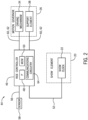
- FIG. 2 is a block diagram of a ride control system 44 for the water-based attraction 10.
- the ride control system 44 includes a controller 46 having a processor 48 such as the illustrated microprocessor, and a memory device 50.
- the controller 46 may also include one or more storage devices and/or other suitable components.
- the processor 48 may include multiple microprocessors, one or more "general-purpose" microprocessors, one or more special-purpose microprocessors, and/or one or more application specific integrated circuits (ASICS), or some combination thereof.
- ASICS application specific integrated circuits
- the processor 48 may include one or more reduced instruction set (RISC) processors.
- RISC reduced instruction set
- the memory device 50 may include a volatile memory, such as random access memory (RAM), and/or a nonvolatile memory, such as read-only memory (ROM).
- the memory device 50 may store a variety of information and may be used for various purposes.
- the memory device 50 may store processor-executable instructions (e.g., firmware or software) for the processor 48 to execute.
- the storage device(s) e.g., nonvolatile storage
- the storage device(s) may include ROM, flash memory, a hard drive, or any other suitable optical, magnetic, or solid-state storage medium, or a combination thereof.
- the storage device(s) may store data (e.g., position data, vehicle geometry data, etc.), instructions (e.g., software or firmware), and any other suitable data.
- the controller 46 may be configured to receive a show timer signal 52 from a show clock 22 of the show element 20.
- the show element 20 may include animatronics, videos, sound effects, or any other special effect.
- the show element 20 may have a start time and end time associated with each ride vehicle 12 within the water-based attraction 10.
- the show timer signal 52 may indicate the start time or the end time of the show element 20.
- the show timer signal 52 may indicated an amount of time remaining before the show element 20 begins.
- the show timer signal 52 may indicate any time value from which the controller 46 may determine a start time or end time of the show element 20.
- the show clock 22 is shown as being resident on the show element 20, it should be understood that the show clock 22 may be resident on the controller 46. Further, the show clock 22 may be a part of a ride clock that controls all show clocks 22 of the show elements 20 as well as ride vehicle dispatch of the attraction 10 as part of the controller 46.
- the controller 46 may be configured to receive a location signal 56 indicative of a location of the ride vehicle 12 within the flow path 14 and/or indicative of a distance to an individual show element 20.
- One or more sensors 58 may be configured to provide the location signal 56 indicative of a position of the ride vehicle 12 in the water-based attraction 10 and output the location signal 56.
- the location signal 56 may indicate a position of the ride vehicle 12 along the flow path 14 with respect to the motion governor 26.
- the location signal 56 may indicate a position of the ride vehicle 12 with respect to the show element 20.
- the location signal 56 may indicate a position of the ride vehicle 12 along the flow path 14 with respect to a sensor 58.
- the location signal 56 may indicate a distance between the sensor 58 and the ride vehicle 12.
- the sensor 58 may be disposed on the motion governor 26 or on the ride vehicle 12.
- the sensor or sensors 58 is disposed adjacent the flume 18 and proximate at least one support element 38.
- the controller 46 is configured to determine a speed of the ride vehicle 12 based at least in part on the location signal 56, e.g., based on a time elapsed between a first location and a second location of the ride vehicle 12.
- the sensor 58 may be configured to output multiple location signals.
- the sensor 58 may output the location signals at regular intervals.
- the controller 46 may determine a distance from the ride vehicle 12 to the sensor 58 at a first time based at least in part on a first location signal. Further, the controller 46 may determine a distance from the ride vehicle 12 to the sensor 58 at a second time based at least in part on a second location signal.
- the controller 46 may be configured to determine the speed of the ride vehicle 12 based on a change in distance of the ride vehicle 12 over time as determined from one or more location signals 56.
- the controller 46 is configured to determine an estimated arrival time of the ride vehicle 12 to the motion governor 26, having the at least one support element 38, based at least in part on the location signal 56.
- the controller 46 may be configured to determine an estimated arrival time to the motion governor 26 based at least in part on the speed of the ride vehicle 12 and a distance between the ride vehicle 12 and the motion governor 26.
- the controller 46 may be configured to generate a control signal 60 based on the estimated arrival time to the motion governor 26 such that the at least one support element 38 is positioned to receive the ride vehicle 12 at the estimated arrival time at the motion governor 26.
- the control signal 60 may include instructions to position the at least one support element 38 such that the ride vehicle 12 is received into a slot between a first support element 38 and a second support element 38 at the motion governor 26.
- the instructions may cause a switch from a retracted or default position outside of the flow path 14 to a deployed or activated position within the flow path 14 and sufficiently protruding into the flow path 14 to contact the ride vehicle 12.
- the controller 46 is configured to determine an estimated arrival time of the ride vehicle 12 to the show element 20 based at least in part on the location signal 56.
- the controller 46 may be configured to generate the control signal 60 based on the estimated arrival time to the show element 20 and the show timer for the show element 20.
- the control signal 60 may include instructions to the motion governor 26 to adjust a rate of rotation of the conveyor 36.
- the control signal 60 may include instructions to slow down the ride vehicle 12 based at least in part on a determination that the ride vehicle 12 will arrive to the show element 20 before a start time of the show element 20.
- the controller 46 may receive the location signal 56 and determine that the ride vehicle 12 the estimated arrival time for the ride vehicle 12 to arrive to the show element 20 is in 30 seconds.
- the controller 46 may receive the show timer signal 52 indicating that the start time for the show element 20 is in 34 seconds. Accordingly, the controller 46 will generate a control signal 60 having instructions to slow down the ride vehicle 12 such that a new arrival time for the ride vehicle 12 is aligned with a start time of the show element 20. Moreover, the control signal 60 may include instructions to speed up the ride vehicle 12 based at least in part on a determination that the ride vehicle 12 will arrive to the show element 20 after a start time of the show element 20.
- the controller 46 may be configured to output the control signal 60 to the motion governor 26. In some embodiments, the controller 46 is configured to output the control signal 60 to the driving mechanism 34 and/or the at least one support element 38. Further, the controller 46 may be configured to output a disengage signal 62 to the motion governor 26 and/or at least one support element 38 in response to determining that the ride vehicle 12 will arrive at the show element 20 on time.
- the at least one support element 38 is configured to avoid contact with the ride vehicle 12 in response to receiving the disengage signal 62. In some embodiments, the at least one support element 38 is configured to retract from the flow path 14 to avoid contact with the ride vehicle 12 in response to the disengage signal 62.
- the controller 46 may determine that the estimated arrival time for the ride vehicle 12 to arrive to the show element 20 is in 34 seconds.
- the controller 46 may receive the show timer signal 52 indicating that the start time for the show element 20 is in 34 seconds.
- the controller 46 is configured to output the disengage signal 62.
- the controller 46, the sensor 58, the show clock 22, the at least one support element 38, and the motion governor 26 may include communications circuitry 64, such as antennas, radio transceiver circuits, signal processing hardware and/or software (e.g., hardware or software filters, A/D converters, multiplexer amplifiers), or a combination thereof.
- the communications circuitry 64 may be configured to communicate over wired or wireless communication paths via IR wireless communication, satellite communication, broadcast radio, microwave radio, Bluetooth, Zigbee, Wifi, UHF, NFC, etc. Such communication may also include intermediate communications devices, such as radio towers, cell towers, etc.
- FIG. 3 is a side view of the motion governor 26 and the ride vehicle 12.
- the ride vehicle 12 has a designated front side 66, rear side 68, and lateral sides 70.
- the front side 66, rear side 68, and lateral sides 70 merely designate an outer portion of the ride vehicle 12 with respect to the flow path 14.
- some ride vehicles 12 may be substantially circular such that the ride vehicle 12 does not have an inherent front side 66.
- the front side 66 of the ride vehicle 12 refers to a side of the ride vehicle 12 facing downstream 72 of the flow path 14 and oriented in the direction of travel of the flow path 14.
- the rear side 68 refers to a portion of the ride vehicle 12 facing upstream 74 of the flow path 14
- the lateral sides 70 refer to portions of the ride vehicle 12 facing perpendicular to the front side 66 and the rear side 68 of the ride vehicle 12.
- the ride vehicle 12 has a bottom portion 76.
- the motion governor 26 includes the at least one support element 38 configured to contact the ride vehicle 12 to control movement of the ride vehicle 12 along the flow path 14.
- the at least one support element 38 may be coupled to a conveyor 36 having a track 78 configured to rotate within the flow path 14.
- the conveyor 36 may be disposed proximate a bottom 80 of the flume 18 such that the ride vehicle 12 passes over the conveyor 36 as the ride vehicle 12 travels along the flow path 14.
- the driving mechanism 34 may be configured to rotate the conveyor 36 based at least in part on the control signal from the controller. In some embodiments, the driving mechanism 34 is configured to adjust a rate of actuation of the conveyor 36 based on the control signal.
- the controller may be configured to generate the control signal to actuate the driving mechanism 34 at a rate configured to slow down the ride vehicle 12 based at least in part on a determination that the ride vehicle 12 will arrive to the show element 20 before a start time of the show element 20.
- the at least one support element 38 may configured to contact a front side 66 of the ride vehicle 12 to decelerate movement of the ride vehicle 12.
- the ride vehicle 12 may be moving along the flow path 14 at a rate such that the ride vehicle 12 will arrive at the show element 20 before the start time of the show element 20.
- the controller generates a control signal to the driving mechanism 34, and in response to the control signal, the driving mechanism 34 rotates the conveyor 36 such that the at least one support element 38 moves along the flow path 14 at a rate slower than the ride vehicle 12.
- the front side 66 of the ride vehicle 12 may contact the at least one support element 38.
- the at least one support element 38 may slow the ride vehicle 12 to the rate of the at least one support element 38.
- the motion governor 26 includes a first support element 82 and a second support element 84.
- the conveyor 36 may be configured to rotate such that the motion governor 26 receives the ride vehicle 12 in a slot 86 disposed between the first support element 82 and the second support element 84.
- the first support element 82 may positioned proximate the front side 66 of the ride vehicle 12 and the second support element 84 may be positioned proximate the rear side 68 of the ride vehicle 12.
- the ride vehicle 12 is configured to decelerate in response to contact with the first support element 82, accelerate in response to contact with the second support element 84, and free float when not in contact with either the first support element 82 or the second support element 84.
- the support element or elements 38 are sized and shaped to come into contact with the ride vehicle 12 when deployed and in position.
- the at least one support element 38 may not contact the bottom portion 76 of the ride vehicle 12 to maintain the floating or buoyant effect experienced by a guest in the ride vehicle 12.
- Each support element 38 may be configured to only restrict movement of the ride vehicle 12 along an axis or in a particular direction.
- the at least one support element 38 may contact the rear side 68 of the ride vehicle 12 in response to a control signal having instructions to accelerate the ride vehicle 12, which restricts movement of the ride vehicle 12 in a rearward direction 88.
- the at least one support element 38 does not contact a bottom portion 76 of the ride vehicle 12. Therefore, the ride vehicle 12 maintains freedom of movement in a vertical direction 90.
- the ride vehicle 12 may rise and fall with respective rising and falling of water in the flume 18.
- the rising and falling of the ride vehicle 12 with respect to the water in the flume 18 may maintain the floating or buoyant effect experienced by a guest in the ride vehicle 12.
- the controller is configured to output the control signal to the driving mechanism 34 to create a show effect.
- the show effect may simulate turbulent water or the ride vehicle crashing into an obstacle.
- the ride vehicle 12 may enter a portion of the water-based attraction 10 configured to simulate white water rapids.
- the controller may output the control signal to the driving mechanism 34 such that the driving mechanism 34 drives the at least one support element 38 into the lateral side 70 of the ride vehicle 12.
- Contact between the ride vehicle 12 and the at least one support element 38 may jolt the ride vehicle 12 in the later direction 120 to simulate the ride vehicle 12 colliding with a rock.
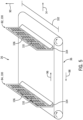
- FIG. 4 is a top view of another embodiment of the motion governor 26 and the ride vehicle 12.
- the motion governor 26 is disposed on a side wall 92 of the flume 18.
- the at least one support element 38 may extend laterally into the flow path 14 from the motion governor 26.
- the at least one support element 38 is coupled to a slide track 94.
- the slide track 94 may be configured to move the at least one support element 38 in the direction of the flow path 14 to accelerate or decelerate the ride vehicle 12.
- the driving mechanism 34 may be configured to drive the at least one support element 38 along the slide track 94 in response to the control signal from the controller.
- the at least one support element 38 is coupled to a conveyor 36 disposed on the side wall92 such that the at least one support element 38 is configured to move relative to the side wall 92 of the flume 18.
- the at least one support element 38 is a paddle 100 configured to contact the front side 66, rear side 68, or lateral side of the ride vehicle 12.
- the paddle 100 may extend along a width 102 of the conveyor 36.
- the width 102 of the conveyor 36 may be similar to a width of the ride vehicle 12.
- the paddle 100 may be coupled to the conveyor 36 at a base 104 of the paddle 100.
- a free end 106 of the paddle 100 may extend out from the conveyor 36 in a direction toward a surface of the water in the flume 18 (e.g., the vertical direction 90) when the paddle 100 is moving in the downstream direction 96.
- the paddle 100 may have a grated form including through passages 110 such that fluid from the flow path 14 passes through at least one interior portion of the paddle 100.
- the grated form may reduce an amount of power required to move the paddle 100 along the flow path 14.
- the driving mechanism 34 may be configured to receive the control signal and drive the at least one support element 38 based at least in part on the control signal.
- the ride vehicle 12 may approach the divergence point 121 of the flow path 14.
- the controller may output the control signal having instructions for the driving mechanism 34 to direct the ride vehicle 12 left to the first flow path 28.
- the driving mechanism 34 may be configured to receive the control signal and drive the at least one support element 38 to the left with respect to the flow path 14.
- the at least one support element 38 may contact a right side 124 of the ride vehicle. The contact between the ride vehicle 12 and the at least one support element 38 may drive the ride vehicle 12 left to the first flow path 28. While the depicted embodiment shows lateral motion effects, it should be understood that the at least one support elements 38 may be configured to extend from one or more side walls 92 of the flume 18 to dynamically adjust an orientation of the ride vehicle 12.
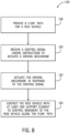
- FIG. 8 is a flow diagram 126 of a method to govern motion of the ride vehicle along the flow path of the water-based ride attraction.
- the method includes the step of providing a flow path for the ride vehicle 128.
- the water-based ride attraction has a water or fluid-filled flume that is configured to provide the flow path for the ride vehicle.
- the method also includes the step of receiving the control signal having instructions to actuate the driving mechanism based at least in part on the location of a ride vehicle and the show timer for a show element 130.
- the controller is configured to determine an estimated arrival time of the ride vehicle to the show element. Further, the controller is configured to determine a rate for the driving mechanism to control movement of the ride vehicle such that the ride arrives at the show element at a start time of the show element based at least in part on the location of the ride vehicle and the show timer.
- the controller is configured to generate the control signal to actuate the driving mechanism at a rate configured to slow down the ride vehicle based at least in part on a determination that the ride vehicle will arrive to the show element before a start time of the show element.
- the controller is configured to generate the control signal to actuate the driving mechanism at a rate configured to speed up the ride vehicle based at least in part on a determination that the ride vehicle will arrive to the show element after a start time of the show element.
- the control signal may be generated based on a determination that the ride vehicle will not arrive at a scheduled start time of the show element based on the location and/or speed of the ride vehicle.
- the method also includes the step of actuating the driving mechanism in response to the control signal 132.
- the at least one support element may be coupled to the driving mechanism and configured to move together with the driving mechanism.
- the method includes the additional step of contacting the ride vehicle with the at least one support element to control movement of the ride vehicle along the flow path 134.
- the at least one support element may contact the ride vehicle at a front side, rear side, or lateral side at an instructed rate, based at least in part on the control signal, to control movement of the ride vehicle along the flow path.
Landscapes
- Fire-Extinguishing By Fire Departments, And Fire-Extinguishing Equipment And Control Thereof (AREA)
- Motorcycle And Bicycle Frame (AREA)
- Control Of Position, Course, Altitude, Or Attitude Of Moving Bodies (AREA)
- Hydraulic Turbines (AREA)
- Other Liquid Machine Or Engine Such As Wave Power Use (AREA)
Abstract
Description
- The present application claims the benefit of
U.S. Provisional Application No. 62/769,996, entitled "Water Amusement Ride Motion Governor" and filed November 20, 2018 - The present disclosure relates generally to the field of amusement parks. Specifically, embodiments of the present disclosure relate to techniques to govern motion of a ride vehicle of an attraction.
- This section is intended to introduce the reader to various aspects of art that may be related to various aspects of the present disclosure, which are described below. This discussion is believed to be helpful in providing the reader with background information to facilitate a better understanding of the various aspects of the present disclosure. Accordingly, it should be understood that these statements are to be read in this light, and not as admissions of prior art.
- Various forms of amusement rides have been used for many years in amusement or theme parks. These amusement rides include water-based rides. Certain water-based rides include show elements, e.g., special effects or animatronic set pieces, at particular locations along a flow path. Generally, water-based rides attempt to align a start time of a show element with an arrival of a ride vehicle to the show element. Some water-based rides adjust a start time of the show element to ensure that the show element is initiated as the ride vehicle arrives. However, adjusting the start time of the show element may lead to inconsistent ride durations and, consequently, inconsistent ride queues. Other water-based rides attempt to adjust the speed of the ride vehicle, such that the ride vehicle arrives to the show element at a set start time for the show element. However, adjusting the speed and/or location of a water-based ride vehicle is complex, particular for water vehicles that are influenced by water current or gravity effects.
- A summary of certain embodiments disclosed herein is set forth below. It should be understood that these aspects are presented merely to provide the reader with a brief summary of these certain embodiments and that these aspects are not intended to limit the scope of this disclosure. Indeed, this disclosure may encompass a variety of aspects that may not be set forth below.
- In accordance with one embodiment, a ride system is provided. The ride system includes a flume providing a flow path of a water ride and configured to accommodate a buoyant ride vehicle. The ride system also includes at least one support element extending into the flow path and at least partially submerged within the flow path. Moreover, the ride system includes a driving mechanism configured to actuate the at least one support element such that the at least one support element moves relative to the flow path in response to a control signal. The at least one support element is configured to contact the buoyant ride vehicle to control movement of the buoyant ride vehicle along the flow path while the at least one support element is being actuated. Further, the ride system includes a controller configured to generate the control signal based at least in part on a location of the buoyant ride vehicle in the flow path and a timer controlling activation of a show element, wherein the show element is located along the flow path.
- In accordance with another embodiment, a ride system is provided. The ride system includes a motion governor. The motion governor includes a conveyor configured to rotate along a track disposed within a flow path of water ride. The motion governor also includes a driving mechanism configured to control rotation of the conveyor in response to a control signal. Further, the motion governor includes at least one support element coupled to the conveyor. The at least one support element is configured to contact a ride vehicle to control movement of the ride vehicle along the flow path. The ride system also includes a controller configured to receive a location signal indicative of a location of the ride vehicle along the flow path, estimate an arrival time to a show element based on the location, determine that the estimated arrival time deviates from a scheduled show element start time, and generate the control signal upon determining that the estimated arrival time deviates from the scheduled show element start time.
- In accordance with another embodiment, a method to govern motion of the ride vehicle along a flow path of the water-based ride attraction is provided. The method includes the step of providing a flow path configured to be traversed by a buoyant ride vehicle. The method also includes the step of receiving a control signal comprising instructions to actuate a driving mechanism based at least in part on a location of the buoyant ride vehicle in the flow path and a timer of a show element. The method also includes the step of actuating the driving mechanism in response to the control signal. At least one support element is coupled to the driving mechanism and configured to move along the flow path as a result of actuating the driving mechanism. The method also includes the step of contacting the ride vehicle with the at least one support element to change a speed of the ride vehicle along the flow path.
- In accordance with another embodiment, a ride system is provided. The ride system includes a controller configured to determine a location of a ride vehicle with respect to a show element. The controller is also configured to determine an estimated arrival of the buoyant ride vehicle at the show element based at least in part on the location. The controller is also configured to determine that the estimated arrival time deviates from a scheduled show element start time. The controller is also configured to generate a control signal comprising instructions to rotate a conveyor upon determining that the estimated arrival time deviates from the scheduled show element start time. The at least one support element is coupled to the conveyor and is configured to contact the buoyant ride vehicle to control movement of the ride vehicle along a flow path based on rotation of the conveyor. The controller is also configured to output the control signal to a motion governor coupled to the conveyor.
- Various aspects of this disclosure may be better understood upon reading the following detailed description and upon reference to the drawings in which:
-
FIG. 1 is a schematic view of a water-based ride attraction, in accordance with present techniques; -
FIG. 2 is a block diagram of a water-based ride attraction control system, in accordance with present techniques; -
FIG. 3 is a side view of a motion governor and a ride vehicle, in accordance with present techniques; -
FIG. 4 is a top view of another embodiment of the motion governor and the ride vehicle, in accordance with present techniques; -
FIG. 5 is a perspective view of the motion governor having a plurality of support elements; -
FIG. 6 is a front view of another embodiment of the motion governor having a support element; -
FIG. 7 is a top view of the water-based ride attraction having a switch track, in accordance with present techniques; and -
FIG. 8 is a flow diagram of a method to govern motion of the ride vehicle along a flow path of the water-based ride attraction, in accordance with present techniques. - One or more specific embodiments will be described below. In an effort to provide a concise description of these embodiments, not all features of an actual implementation are described in the specification. It should be appreciated that in the development of any such actual implementation, as in any engineering or design project, numerous implementation-specific decisions must be made to achieve the developers' specific goals, such as compliance with system-related and business-related constraints, which may vary from one implementation to another. Moreover, it should be appreciated that such a development effort might be complex and time consuming, but would nevertheless be a routine undertaking of design, fabrication, and manufacture for those of ordinary skill having the benefit of this disclosure.
- When introducing elements of various embodiments of the present disclosure, the articles "a," "an," and "the" are intended to mean that there are one or more of the elements. The terms "comprising," "including," and "having" are intended to be inclusive and mean that there may be additional elements other than the listed elements. Additionally, it should be understood that references to "one embodiment" or "an embodiment" of the present disclosure are not intended to be interpreted as excluding the existence of additional embodiments that also incorporate the recited features.
- Theme park or amusement park attractions have become increasingly popular, and various amusement park attractions have been created to provide passengers with unique motion and visual experiences. These theme park or amusement park attractions include water-based attractions. Water-based attractions may have at least one ride vehicle configured to carry passengers along a flow path. To improve the immersive experience, the attraction may also have one or more show elements, e.g., special effects, movable set pieces, distributed along the ride or flow path of the ride vehicle. However, in contrast to track-based vehicles that move along a track at relatively predictable speeds based on the motor control signals, buoyant water-ride vehicles are subject to variable forces such as water current, gravity, water levels, passenger weight. Accordingly, buoyant water ride vehicles operate with wider time slippage over the course of the ride and a greater variability in speed. Thus, for certain types of water rides, it is difficult to predict or control an arrival time of each ride vehicle to the locations associated with each show piece to align initiation of the show piece motion and/or effect with the arrival of the ride vehicle. In certain cases, to ensure that a vehicle arrives to a show element at a start time of the show element, the water-based attraction may dynamically adjust the start time of the show element. However, such adjustment permits widely varying ride times, which may in turn cause excess wait times for the ride. Alternatively, certain rides may include features that adjust the speed of the ride vehicle along the flow path using a track or other locking system that couples the ride vehicle to the flume to control advancement of the ride vehicle. However, such tracks or other locking systems limit freedom of motion of the ride vehicle in a manner that reduces a floating or buoyant effect experienced by a guest in the ride vehicle. Thus, in accordance with certain embodiments of this disclosure, a system or method for adjusting the speed of the ride vehicle, e.g., to achieve alignment with one or more show elements, while maintaining the floating or buoyant effect experienced by a guest in the ride vehicle is provided.
-
FIG. 1 is a schematic view of a water-basedattraction 10 with aride vehicle 12 traveling along aflow path 14 of the water-based attraction during a ride cycle. Theride vehicle 12 includes at least oneride seat 16 for a passenger of theride vehicle 12. During the ride cycle, the passenger may sit in the at least one ride seat as theride vehicle 12 floats along theflow path 14. Theride vehicle 12 floats along theflow path 14 within a flume 18 (i.e., a channel for water). Theflow path 14 may be defined by theflume 18. However, in some embodiments, water jets, propellers, or other suitable devices may alter theflow path 14 within theflume 18. In some embodiments, a current of the water or fluid within theflow path 14 propels theride vehicle 12 along theflow path 14 in a desired direction or axis of travel (e.g. along arrow 19). - In some embodiments, the water-based
attraction 10 includes at least oneshow element 20 located along theflow path 14. The at least oneshow element 20 may include animatronics, videos, sound effects, light effects, motion effects, water effects, or any other special effect. The at least oneshow element 20 may have a start time and end time. In some embodiments, a scheduled show element start time of theshow element 20 is based at least in part on ashow clock 22. Thus, the at least oneshow element 20 may start at regular or scheduled timed intervals that correspond with estimated arrival ofindividual ride vehicles 12 at theshow element 20. In some embodiments, theshow element 20 starts according to pre-scheduled start times. Thus, theride vehicle 12 may should arrive at theshow element 20 at a predetermined time so that the passenger experiences theshow element 20 without missing a beginning or end of theshow element 20. Starting theshow element 20 at regular intervals or according to prescheduled start times may promote ride throughput predictability as compared to ashow element 20 having varying start times. - The water-based
attraction 10 has one ormore motion governors 26 that may at least in part control movement of theride vehicle 12 along theflow path 14 or along certain portions of theflow path 14. In some embodiments, themotion governor 26 is configured to control motion of theride vehicle 12 such that theride vehicle 12 arrives at theshow element 20 at the predetermined time or at the scheduled start time of theshow element 20 so that the passenger may experience theshow element 20 without missing a beginning or end of the effect. In some embodiments, the one ormore motion governors 26 may only be configured to control motion of theride vehicle 12 when the ride vehicle is predicted to arrive before or after the predetermined time or at the scheduled start time of theshow element 20. In some embodiments, theshow element 20 includes an introduction buffer configured to form an arrival window for theride vehicle 12. The introduction buffer may include preliminary videos, sound effects, light effects, motion effects, water effects, or any other special effect. For example, the introduction buffer may include a ten second window of music playing prior to the start of theshow element 20. In some embodiments, the one ormore motion governors 26 are configured to control motion of theride vehicle 12 such that theride vehicle 12 arrives at theshow element 20 during the arrival window. Further, in some embodiments, the one ormore motion governors 26 may only be configured to control motion of theride vehicle 12 when theride vehicle 12 is predicted to arrive before or after the arrival window. - In some embodiments, the
motion governor 26 operates in conjunction with theshow element 20 and is configured to contribute to an attraction effect (e.g., sudden acceleration or deceleration, rocking motions, etc.). Moreover, in some embodiments, themotion governor 26 is configured to direct theride vehicle 12 to one of afirst flow path 28 orsecond flow path 30 at adivergence 32 in theflow path 14. Themotion governor 26 may facilitate desired movement of theride vehicle 12 along theflume 18. - The
motion governor 26 includes adriving mechanism 34. In some embodiments, thedriving mechanism 34 drives rotation of aconveyor 36 in response to a control signal. Thedriving mechanism 34 may operate at varying speeds and torques to drive theconveyor 36. At least onesupport element 38 may be coupled to theconveyor 36. As theconveyor 36 turns, thesupport element 38 may contact theride vehicle 12 to control movement of theride vehicle 12 along theflow path 14. For example, thesupport element 38 may contact a downstream orfront portion 40 of theride vehicle 12 to decelerate theride vehicle 12. In another example, thesupport element 38 may contact an upstream orrear portion 42 of theride vehicle 12 to accelerate theride vehicle 12. In some embodiments, thesupport element 38 is coupled directly to thedriving mechanism 34 or to an adapter coupled to thedriving mechanism 34. - The disclosed
motion governor 26 may operate to adjust or change a speed, position, or direction of a floating orbuoyant ride vehicle 12 that is not directly affixed or coupled to theflume 18 and that floats within theflow path 14. By engaging support elements that reversibly contact theride vehicle 12 to push theride vehicle 12,individual ride vehicles 12 may be nudged into position to arrive atvarious show elements 20 on time. The motion governor orgovernors 26 may operate on an as-needed basis and may engage in response toindividual ride vehicles 12 deviating from a desired speed or path and to nudgesuch ride vehicles 12 back into position. Accordingly, for a water-basedattraction 10 that accommodatesmultiple ride vehicles 12, either in parallel or in series, themotion governor 26 may only directly engage a subset of theride vehicles 12 while allowingother ride vehicles 12 to progress without adjustments depending on progression of theride vehicles 12 along theflow path 14. In this manner, in certain embodiments, the disclosed techniques permit minor position, orientation, and/or speed adjustments that may be relatively unnoticeable to the passengers and while maintaining a buoyant feeling by avoiding locking theride vehicles 12 onto tracks or tow elements. -
FIG. 2 is a block diagram of aride control system 44 for the water-basedattraction 10. In some embodiments, theride control system 44 includes acontroller 46 having aprocessor 48 such as the illustrated microprocessor, and amemory device 50. Thecontroller 46 may also include one or more storage devices and/or other suitable components. Moreover, theprocessor 48 may include multiple microprocessors, one or more "general-purpose" microprocessors, one or more special-purpose microprocessors, and/or one or more application specific integrated circuits (ASICS), or some combination thereof. For example, theprocessor 48 may include one or more reduced instruction set (RISC) processors. - The
memory device 50 may include a volatile memory, such as random access memory (RAM), and/or a nonvolatile memory, such as read-only memory (ROM). Thememory device 50 may store a variety of information and may be used for various purposes. For example, thememory device 50 may store processor-executable instructions (e.g., firmware or software) for theprocessor 48 to execute. The storage device(s) (e.g., nonvolatile storage) may include ROM, flash memory, a hard drive, or any other suitable optical, magnetic, or solid-state storage medium, or a combination thereof. The storage device(s) may store data (e.g., position data, vehicle geometry data, etc.), instructions (e.g., software or firmware), and any other suitable data. - The
controller 46 may be configured to receive ashow timer signal 52 from ashow clock 22 of theshow element 20. As set forth above, theshow element 20 may include animatronics, videos, sound effects, or any other special effect. As such, theshow element 20 may have a start time and end time associated with eachride vehicle 12 within the water-basedattraction 10. Theshow timer signal 52 may indicate the start time or the end time of theshow element 20. In some embodiments, theshow timer signal 52 may indicated an amount of time remaining before theshow element 20 begins. Theshow timer signal 52 may indicate any time value from which thecontroller 46 may determine a start time or end time of theshow element 20. While theshow clock 22 is shown as being resident on theshow element 20, it should be understood that theshow clock 22 may be resident on thecontroller 46. Further, theshow clock 22 may be a part of a ride clock that controls all showclocks 22 of theshow elements 20 as well as ride vehicle dispatch of theattraction 10 as part of thecontroller 46. - Moreover, the
controller 46 may be configured to receive alocation signal 56 indicative of a location of theride vehicle 12 within theflow path 14 and/or indicative of a distance to anindividual show element 20. One ormore sensors 58 may be configured to provide thelocation signal 56 indicative of a position of theride vehicle 12 in the water-basedattraction 10 and output thelocation signal 56. Thelocation signal 56 may indicate a position of theride vehicle 12 along theflow path 14 with respect to themotion governor 26. In some embodiments, thelocation signal 56 may indicate a position of theride vehicle 12 with respect to theshow element 20. However, in another embodiment, thelocation signal 56 may indicate a position of theride vehicle 12 along theflow path 14 with respect to asensor 58. Thelocation signal 56 may indicate a distance between thesensor 58 and theride vehicle 12. Thesensor 58 may be disposed on themotion governor 26 or on theride vehicle 12. However, in other embodiments, the sensor orsensors 58 is disposed adjacent theflume 18 and proximate at least onesupport element 38. - In some embodiments, the
controller 46 is configured to determine a speed of theride vehicle 12 based at least in part on thelocation signal 56, e.g., based on a time elapsed between a first location and a second location of theride vehicle 12. Thesensor 58 may be configured to output multiple location signals. Thesensor 58 may output the location signals at regular intervals. In one embodiment, thecontroller 46 may determine a distance from theride vehicle 12 to thesensor 58 at a first time based at least in part on a first location signal. Further, thecontroller 46 may determine a distance from theride vehicle 12 to thesensor 58 at a second time based at least in part on a second location signal. Thecontroller 46 may be configured to determine the speed of theride vehicle 12 based on a change in distance of theride vehicle 12 over time as determined from one or more location signals 56. - In some embodiments, the
controller 46 is configured to determine an estimated arrival time of theride vehicle 12 to themotion governor 26, having the at least onesupport element 38, based at least in part on thelocation signal 56. Thecontroller 46 may be configured to determine an estimated arrival time to themotion governor 26 based at least in part on the speed of theride vehicle 12 and a distance between theride vehicle 12 and themotion governor 26. Thecontroller 46 may be configured to generate a control signal 60 based on the estimated arrival time to themotion governor 26 such that the at least onesupport element 38 is positioned to receive theride vehicle 12 at the estimated arrival time at themotion governor 26. The control signal 60 may include instructions to position the at least onesupport element 38 such that theride vehicle 12 is received into a slot between afirst support element 38 and asecond support element 38 at themotion governor 26. The instructions may cause a switch from a retracted or default position outside of theflow path 14 to a deployed or activated position within theflow path 14 and sufficiently protruding into theflow path 14 to contact theride vehicle 12. - In another embodiment, the
controller 46 is configured to determine an estimated arrival time of theride vehicle 12 to theshow element 20 based at least in part on thelocation signal 56. Thecontroller 46 may be configured to generate the control signal 60 based on the estimated arrival time to theshow element 20 and the show timer for theshow element 20. The control signal 60 may include instructions to themotion governor 26 to adjust a rate of rotation of theconveyor 36. The control signal 60 may include instructions to slow down theride vehicle 12 based at least in part on a determination that theride vehicle 12 will arrive to theshow element 20 before a start time of theshow element 20. For example, thecontroller 46 may receive thelocation signal 56 and determine that theride vehicle 12 the estimated arrival time for theride vehicle 12 to arrive to theshow element 20 is in 30 seconds. Thecontroller 46 may receive theshow timer signal 52 indicating that the start time for theshow element 20 is in 34 seconds. Accordingly, thecontroller 46 will generate a control signal 60 having instructions to slow down theride vehicle 12 such that a new arrival time for theride vehicle 12 is aligned with a start time of theshow element 20. Moreover, the control signal 60 may include instructions to speed up theride vehicle 12 based at least in part on a determination that theride vehicle 12 will arrive to theshow element 20 after a start time of theshow element 20. - The
controller 46 may be configured to output the control signal 60 to themotion governor 26. In some embodiments, thecontroller 46 is configured to output the control signal 60 to thedriving mechanism 34 and/or the at least onesupport element 38. Further, thecontroller 46 may be configured to output a disengage signal 62 to themotion governor 26 and/or at least onesupport element 38 in response to determining that theride vehicle 12 will arrive at theshow element 20 on time. The at least onesupport element 38 is configured to avoid contact with theride vehicle 12 in response to receiving the disengage signal 62. In some embodiments, the at least onesupport element 38 is configured to retract from theflow path 14 to avoid contact with theride vehicle 12 in response to the disengage signal 62. For example, thecontroller 46 may determine that the estimated arrival time for theride vehicle 12 to arrive to theshow element 20 is in 34 seconds. Thecontroller 46 may receive theshow timer signal 52 indicating that the start time for theshow element 20 is in 34 seconds. Thus theride vehicle 12 will arrive at theshow element 20 on time, and speed corrections to theride vehicle 12 are not required. As such, thecontroller 46 is configured to output the disengage signal 62. - To facilitate these communications, the
controller 46, thesensor 58, theshow clock 22, the at least onesupport element 38, and themotion governor 26 may includecommunications circuitry 64, such as antennas, radio transceiver circuits, signal processing hardware and/or software (e.g., hardware or software filters, A/D converters, multiplexer amplifiers), or a combination thereof. Thecommunications circuitry 64 may be configured to communicate over wired or wireless communication paths via IR wireless communication, satellite communication, broadcast radio, microwave radio, Bluetooth, Zigbee, Wifi, UHF, NFC, etc. Such communication may also include intermediate communications devices, such as radio towers, cell towers, etc. -
FIG. 3 is a side view of themotion governor 26 and theride vehicle 12. In some embodiments, theride vehicle 12 has a designatedfront side 66,rear side 68, and lateral sides 70. However, in other embodiments, thefront side 66,rear side 68, andlateral sides 70 merely designate an outer portion of theride vehicle 12 with respect to theflow path 14. For example, someride vehicles 12 may be substantially circular such that theride vehicle 12 does not have an inherentfront side 66. In such cases, thefront side 66 of theride vehicle 12 refers to a side of theride vehicle 12 facing downstream 72 of theflow path 14 and oriented in the direction of travel of theflow path 14. Similarly, therear side 68 refers to a portion of theride vehicle 12 facing upstream 74 of theflow path 14, and the lateral sides 70 refer to portions of theride vehicle 12 facing perpendicular to thefront side 66 and therear side 68 of theride vehicle 12. Moreover, theride vehicle 12 has abottom portion 76. - In some embodiments, the
motion governor 26 includes the at least onesupport element 38 configured to contact theride vehicle 12 to control movement of theride vehicle 12 along theflow path 14. The at least onesupport element 38 may be coupled to aconveyor 36 having atrack 78 configured to rotate within theflow path 14. Theconveyor 36 may be disposed proximate a bottom 80 of theflume 18 such that theride vehicle 12 passes over theconveyor 36 as theride vehicle 12 travels along theflow path 14. Thedriving mechanism 34 may be configured to rotate theconveyor 36 based at least in part on the control signal from the controller. In some embodiments, thedriving mechanism 34 is configured to adjust a rate of actuation of theconveyor 36 based on the control signal. The controller may be configured to generate the control signal to actuate thedriving mechanism 34 at a rate configured to slow down theride vehicle 12 based at least in part on a determination that theride vehicle 12 will arrive to theshow element 20 before a start time of theshow element 20. The at least onesupport element 38 may configured to contact afront side 66 of theride vehicle 12 to decelerate movement of theride vehicle 12. For example, theride vehicle 12 may be moving along theflow path 14 at a rate such that theride vehicle 12 will arrive at theshow element 20 before the start time of theshow element 20. As such, the controller generates a control signal to thedriving mechanism 34, and in response to the control signal, thedriving mechanism 34 rotates theconveyor 36 such that the at least onesupport element 38 moves along theflow path 14 at a rate slower than theride vehicle 12. Thefront side 66 of theride vehicle 12 may contact the at least onesupport element 38. The at least onesupport element 38 may slow theride vehicle 12 to the rate of the at least onesupport element 38. - In another embodiment, the controller is configured to generate a control signal to actuate the
driving mechanism 34 at a rate configured to speed up theride vehicle 12 based at least in part on a determination that theride vehicle 12 will arrive to theshow element 20 after a start time of theshow element 20. The at least onesupport element 38 may configured to contact therear side 68 of theride vehicle 12 to accelerate movement or maintain movement of theride vehicle 12. - In some embodiments, the
motion governor 26 includes a first support element 82 and a second support element 84. In some embodiments, theconveyor 36 may be configured to rotate such that themotion governor 26 receives theride vehicle 12 in aslot 86 disposed between the first support element 82 and the second support element 84. The first support element 82 may positioned proximate thefront side 66 of theride vehicle 12 and the second support element 84 may be positioned proximate therear side 68 of theride vehicle 12. In some embodiments, theride vehicle 12 is configured to decelerate in response to contact with the first support element 82, accelerate in response to contact with the second support element 84, and free float when not in contact with either the first support element 82 or the second support element 84. The support element orelements 38 are sized and shaped to come into contact with theride vehicle 12 when deployed and in position. - The at least one
support element 38 may not contact thebottom portion 76 of theride vehicle 12 to maintain the floating or buoyant effect experienced by a guest in theride vehicle 12. Eachsupport element 38 may be configured to only restrict movement of theride vehicle 12 along an axis or in a particular direction. For example, the at least onesupport element 38 may contact therear side 68 of theride vehicle 12 in response to a control signal having instructions to accelerate theride vehicle 12, which restricts movement of theride vehicle 12 in a rearward direction 88. The at least onesupport element 38 does not contact abottom portion 76 of theride vehicle 12. Therefore, theride vehicle 12 maintains freedom of movement in avertical direction 90. As such, theride vehicle 12 may rise and fall with respective rising and falling of water in theflume 18. The rising and falling of theride vehicle 12 with respect to the water in theflume 18 may maintain the floating or buoyant effect experienced by a guest in theride vehicle 12. - In some embodiments, the controller is configured to output the control signal to the
driving mechanism 34 to create a show effect. The show effect may simulate turbulent water or the ride vehicle crashing into an obstacle. For example, theride vehicle 12 may enter a portion of the water-basedattraction 10 configured to simulate white water rapids. The controller may output the control signal to thedriving mechanism 34 such that thedriving mechanism 34 drives the at least onesupport element 38 into thelateral side 70 of theride vehicle 12. Contact between theride vehicle 12 and the at least onesupport element 38 may jolt theride vehicle 12 in thelater direction 120 to simulate theride vehicle 12 colliding with a rock.FIG. 4 is a top view of another embodiment of themotion governor 26 and theride vehicle 12. In some embodiments, themotion governor 26 is disposed on aside wall 92 of theflume 18. The at least onesupport element 38 may extend laterally into theflow path 14 from themotion governor 26. In some embodiments, the at least onesupport element 38 is coupled to aslide track 94. Theslide track 94 may be configured to move the at least onesupport element 38 in the direction of theflow path 14 to accelerate or decelerate theride vehicle 12. Moreover, thedriving mechanism 34 may be configured to drive the at least onesupport element 38 along theslide track 94 in response to the control signal from the controller. In some embodiments, the at least onesupport element 38 is coupled to aconveyor 36 disposed on the side wall92 such that the at least onesupport element 38 is configured to move relative to theside wall 92 of theflume 18. -
FIG. 5 is a perspective view of themotion governor 26 having the first support element 82 and the second support element 84. The first support element 82 may be disposed downstream 72 relative to the second support element 84. Theconveyor 36 may be configured to move the first support element 82 and the second support element 84 in adownstream direction 96 to control movement of theride vehicle 12. Thedownstream direction 96 may be the direction of theflow path 14 in theflume 18. Theconveyor 36 may move the at least onesupport element 38 in anupstream direction 98 after the at least onesupport element 38 reaches a downstream end of theconveyor 36. - In some embodiments, the at least one
support element 38 is apaddle 100 configured to contact thefront side 66,rear side 68, or lateral side of theride vehicle 12. Thepaddle 100 may extend along awidth 102 of theconveyor 36. Thewidth 102 of the conveyor 36may be similar to a width of theride vehicle 12. Moreover, thepaddle 100 may be coupled to theconveyor 36 at abase 104 of thepaddle 100. Afree end 106 of thepaddle 100 may extend out from theconveyor 36 in a direction toward a surface of the water in the flume 18 (e.g., the vertical direction 90) when thepaddle 100 is moving in thedownstream direction 96. However, thefree end 106 of thepaddle 100 may be submerged under the surface of the water in theflume 18 such that thepaddle 100 may not be visible to a guest in theride vehicle 12. Thepaddle 100 may have a grated form including throughpassages 110 such that fluid from theflow path 14 passes through at least one interior portion of thepaddle 100. The grated form may reduce an amount of power required to move thepaddle 100 along theflow path 14. -
FIG. 6 is a front view of another embodiment of themotion governor 26 having at least onesupport element 38. The at least onesupport element 38 may have a rod shape. Moreover, the at least onesupport element 38 may have a tapered rod shape. The at least onesupport element 38 may be coupled to themotion governor 26 at abase end 112. The tapered rod shape may have a decreasing diameter along a length of the at least onesupport element 38 such that a diameter at thebase end 112 of the at least onesupport element 38 is greater than a diameter at afree end 114 of the at least onesupport element 38. In some embodiments, thefree end 114 of the at least onesupport element 38 may extend out from themotion governor 26 in lateral direction. In some embodiments, the at least onesupport element 38 may extend out from themotion governor 26 in ahorizontal direction 116. The at least onesupport element 38 may be submerged under the surface of thewater 118 in theflume 18. However, in another embodiment, the at least onesupport element 38 may be fully or partially above the surface of thewater 118 in theflume 18. -
FIG. 7 is a top view of the water-basedattraction 10 having a switch track and in which an orientation of theride vehicle 12 may be altered using the disclosed techniques. In some embodiments, thedriving mechanism 34 is configured to drive the at least onesupport element 38 in alateral direction 120 with respect to theflow path 14. As such, the at least onesupport element 38 is configure to contact thelateral side 70 of theride vehicle 12 to cause lateral movement of theride vehicle 12. Moreover, thedriving mechanism 34 may be oriented in a direction transverse to theflow path 122. In another embodiment, theflow path 14 may split into thefirst flow path 28 and thesecond flow path 30 at a divergence in theflow path 14. The controller may be configured to output the control signal to direct theride vehicle 12 to thefirst flow path 28 or thesecond flow path 30. Thedriving mechanism 34 may be configured to receive the control signal and drive the at least onesupport element 38 based at least in part on the control signal. For example, theride vehicle 12 may approach thedivergence point 121 of theflow path 14. The controller may output the control signal having instructions for thedriving mechanism 34 to direct theride vehicle 12 left to thefirst flow path 28. Thedriving mechanism 34 may be configured to receive the control signal and drive the at least onesupport element 38 to the left with respect to theflow path 14. The at least onesupport element 38 may contact a right side 124 of the ride vehicle. The contact between theride vehicle 12 and the at least onesupport element 38 may drive theride vehicle 12 left to thefirst flow path 28. While the depicted embodiment shows lateral motion effects, it should be understood that the at least onesupport elements 38 may be configured to extend from one ormore side walls 92 of theflume 18 to dynamically adjust an orientation of theride vehicle 12. -
FIG. 8 is a flow diagram 126 of a method to govern motion of the ride vehicle along the flow path of the water-based ride attraction. The method includes the step of providing a flow path for theride vehicle 128. The water-based ride attraction has a water or fluid-filled flume that is configured to provide the flow path for the ride vehicle. - The method also includes the step of receiving the control signal having instructions to actuate the driving mechanism based at least in part on the location of a ride vehicle and the show timer for a
show element 130. As set forth above, the controller is configured to determine an estimated arrival time of the ride vehicle to the show element. Further, the controller is configured to determine a rate for the driving mechanism to control movement of the ride vehicle such that the ride arrives at the show element at a start time of the show element based at least in part on the location of the ride vehicle and the show timer. The controller is configured to generate the control signal to actuate the driving mechanism at a rate configured to slow down the ride vehicle based at least in part on a determination that the ride vehicle will arrive to the show element before a start time of the show element. Moreover, the controller is configured to generate the control signal to actuate the driving mechanism at a rate configured to speed up the ride vehicle based at least in part on a determination that the ride vehicle will arrive to the show element after a start time of the show element. The control signal may be generated based on a determination that the ride vehicle will not arrive at a scheduled start time of the show element based on the location and/or speed of the ride vehicle. - The method also includes the step of actuating the driving mechanism in response to the
control signal 132. The at least one support element may be coupled to the driving mechanism and configured to move together with the driving mechanism. The method includes the additional step of contacting the ride vehicle with the at least one support element to control movement of the ride vehicle along theflow path 134. The at least one support element may contact the ride vehicle at a front side, rear side, or lateral side at an instructed rate, based at least in part on the control signal, to control movement of the ride vehicle along the flow path. - While only certain features and embodiments have been illustrated and described, many modifications and changes may occur to those skilled in the art (e.g., variations in sizes, dimensions, structures, shapes and proportions of the various elements, values of parameters (e.g., temperatures, pressures, etc.), mounting arrangements, use of materials, colors, orientations, etc.) without materially departing from the novel teachings and advantages of the disclosed subject matter. The order or sequence of any process or method steps may be varied or re-sequenced according to alternative embodiments. It is, therefore, to be understood that the appended claims are intended to cover all such modifications and changes as fall within the true spirit of the disclosure. Furthermore, in an effort to provide a concise description of the exemplary embodiments, all features of an actual implementation may not have been described. It should be appreciated that in the development of any such actual implementation, as in any engineering or design project, numerous implementation specific decisions may be made. Such a development effort might be complex and time consuming, but would nevertheless be a routine undertaking of design, fabrication, and manufacture for those of ordinary skill having the benefit of this disclosure, without undue experimentation.
- The techniques presented and claimed herein are referenced and applied to material objects and concrete examples of a practical nature that demonstrably improve the present technical field and, as such, are not abstract, intangible or purely theoretical. Further, if any claims appended to the end of this specification contain one or more elements designated as "means for [perform]ing [a function]..." or "step for [perform]ing [a function]...", it is intended that such elements are to be interpreted under 35 U.S.C. 112(f). However, for any claims containing elements designated in any other manner, it is intended that such elements are not to be interpreted under 35 U.S.C. 112(f).
- Further features and aspects of the invention may reside in the below clauses:
- 1. A ride system, comprising:
- a flume providing a flow path of a water ride and configured to accommodate a buoyant ride vehicle;
- at least one support element extending into the flow path and at least partially submerged within the flow path;
- a driving mechanism configured to actuate the at least one support element such that the at least one support element moves relative to the flow path in response to a control signal, wherein the at least one support element is configured to contact the buoyant ride vehicle to control movement of the buoyant ride vehicle along the flow path while the at least one support element is being actuated; and
- a controller configured to generate the control signal based at least in part on a location of the buoyant ride vehicle in the flow path and a timer controlling activation of a show element, wherein the show element is located along the flow path.
- 2. The ride system of clause 1, wherein the driving mechanism is configured to adjust a rate of actuation of the at least one support element based on the control signal.
- 3. The ride system of clause 1, wherein the driving mechanism is configured to rotate a conveyor, the conveyor disposed within the flow path, and wherein the at least one support element is coupled to the conveyor and configured to move in conjunction with rotation of the conveyor.
- 4. The ride system of clause 1, wherein the driving mechanism is configured to drive the at least one support element along a slide track in response to the control signal.
- 5. The ride system of clause 1, wherein the at least one support element is configured to contact a rear side of the buoyant ride vehicle to accelerate movement or maintain movement of the buoyant ride vehicle.
- 6. The ride system of clause 1, wherein the at least one support element is configured to contact a front side of the buoyant ride vehicle to decelerate movement of the buoyant ride vehicle.
- 7. The ride system of clause 1, wherein the at least one support element is configured to contact a lateral side of the buoyant ride vehicle to cause lateral movement of the buoyant ride vehicle.
- 8. The ride system of clause 1, wherein the flow path separates into a first flow path and a second flow path at a divergence point, and wherein the at least one support element is configured to move the buoyant ride vehicle toward the first flow path or the second flow path at the divergence point based at least in part on the control signal.
- 9. The ride system of clause 1, further comprising a sensor configured to detect a location of the buoyant ride vehicle in the flow path and output a location signal indicative of a distance between the buoyant ride vehicle and the show element.
- 10. The ride system of clause 9, wherein the controller is configured to determine a speed of the buoyant ride vehicle and an estimated arrival time of the buoyant ride vehicle to the show element based at least in part on the location signal.
- 11. A ride system, comprising:
a motion governor comprising:
a conveyor configured to rotate along a track disposed within a flow path of a water ride;- a driving mechanism configured to control rotation of the conveyor in response to a control signal; and
- at least one support element coupled to the conveyor, wherein the at least one support element is configured to contact a ride vehicle to control movement of the ride vehicle along the flow path; and
a controller configured to receive a location signal indicative of a location of the ride vehicle along the flow path; estimate an arrival time to a show element based on the location; determine that the estimated arrival time deviates from a scheduled show element start time; and generate the control signal upon determining that the estimated arrival time deviates from the scheduled show element start time.
- 12. The ride system of clause 11, wherein the at least one support element comprises a paddle configured to contact a front, rear, or lateral side of the ride vehicle or a combination thereof.
- 13. The ride system of
clause 12, wherein the paddle comprises a plurality of through passages such that fluid from the flow path passes through at least one interior portion of the paddle. - 14. The ride system of clause 11, wherein the at least one support element is configured to be retracted or positioned out of the flow path in a default position and wherein the control signal causes deployment of the at least one support element into the flow path in an activated position.
- 15. The ride system of clause 11, wherein the at least one support element comprises a first support element and a second support element, wherein the first support element is positioned proximate a front side of the ride vehicle and the second support element is positioned proximate a rear side of the ride vehicle, and wherein the ride vehicle is configured to decelerate in response to contact with the first support element,
accelerate in response to contact with the second support element, and free float when disposed between the first support element and the second support element. - 16. The ride system of clause 11, wherein the controller generates the control signal to control rotation of the conveyor based on the location of the ride vehicle and a conveyor location such that rotation of the conveyor moves the at least one support element towards the ride vehicle.
- 17.The ride system of
clause 16, wherein the control signal causes the conveyor to move the at least one support element along an axis of travel of the ride vehicle in the flow path. - 18. The ride system of clause 11, wherein the at least one support element is not fixed to the ride vehicle.
- 19. A method, comprising:
- providing a flow path configured to be traversed by a buoyant ride vehicle;
- receiving a control signal comprising instructions to actuate a driving mechanism
- based at least in part on a location of the buoyant ride vehicle in the flow path and a timer of a show element;
- actuating the driving mechanism in response to the control signal, wherein at least one support element is coupled to the driving mechanism and configured to move along the flow path as a result of actuating the driving mechanism; and
- contacting the buoyant ride vehicle with the at least one support element to change a speed of the ride vehicle along the flow path.
- 20. The method of
clause 19, moving the at least one support element into the flow path from a default position out of the flow path based on the location of the buoyant ride vehicle such that the at least one support element moves into the flow path
to be positioned at or near a rear or a lateral side of the buoyant ride vehicle to push the buoyant ride vehicle within the flow path. - 21. The method of
clause 19, comprising adjusting a rate of rotation of a conveyor of the driving mechanism based on the control signal. - 22. A ride system, comprising:
- a controller configured to:
- determine a location of a buoyant ride vehicle in a flow path and with respect to a show element;
- determine an estimated arrival time of the buoyant ride vehicle at the show element based at least in part on the location;
- determine that the estimated arrival time deviates from a scheduled show element start time;
- generate a control signal comprising instructions to rotate a conveyor upon determining that the estimated arrival time deviates from the scheduled show element start time; wherein at least one support element is coupled to the conveyor and is configured to contact the buoyant ride vehicle to control movement of the buoyant ride vehicle along the flow path based on rotation of the conveyor; and
- output the control signal to a motion governor coupled to the conveyor.
- a controller configured to:
- 23. The ride system of
clause 22, wherein the controller is configured to generate the control signal to actuate a driving mechanism at a rate configured to slow down the buoyant ride vehicle based at least in part on a determination that the buoyant ride vehicle will arrive to the show element before a scheduled show element start time. - 24. The ride system of
clause 22, wherein the controller is configured to generate the control signal to actuate a driving mechanism at a rate configured to increase
a speed of the buoyant ride vehicle in the flow path based at least in part on a determination that the buoyant ride vehicle will arrive to the show element after a schedule show element start time. - 25.The ride system of
clause 22, wherein the control system is configured to output a disengage control signal in response to determining that the buoyant ride vehicle will arrive at the show element on time, wherein the at least one support element is configured retract from the flow path to avoid contact with the buoyant ride vehicle in response to the disengage control signal.
Claims (15)
- A ride system, comprising:a flume providing a flow path (14) of a water ride and configured to accommodate a buoyant ride vehicle (12);at least one support element (38) extending into the flow path (14) and at least partially submerged within the flow path (14);a driving mechanism (34) configured to actuate the at least one support element (38) such that the at least one support element (38) moves relative to the flow path (14) in response to a control signal, wherein the at least one support element (38) is configured to contact the buoyant ride vehicle (12) to control movement of the buoyant ride vehicle (12) along the flow path (14) while the at least one support element (38) is being actuated; anda controller (46) configured to generate the control signal based at least in part on a location of the buoyant ride vehicle (12) in the flow path (14) and a timer controlling activation of a show element (20), wherein the show element (20) is located along the flow path (14).
- The ride system of claim 1, wherein the driving mechanism (34) is configured to adjust a rate of actuation of the at least one support element (38) based on the control signal.
- The ride system of claim 1, wherein the driving mechanism (34) is configured to rotate a conveyor (36), the conveyor (36) disposed within the flow path (14), and wherein the at least one support element (38) is coupled to the conveyor (36) and configured to move in conjunction with rotation of the conveyor (36).
- The ride system of claim 1, wherein the driving mechanism (34) is configured to drive the at least one support element (38) along a slide track in response to the control signal.
- The ride system of claim 1, wherein the at least one support element (38) is configured to contact a rear side of the buoyant ride vehicle (12) to accelerate movement or maintain movement of the buoyant ride vehicle (12).
- The ride system of claim 1, wherein the at least one support element (38) is configured to contact a front side of the buoyant ride vehicle (12) to decelerate movement of the buoyant ride vehicle (12).
- The ride system of claim 1, wherein the at least one support element (38) is configured to contact a lateral side of the buoyant ride vehicle (12) to cause lateral movement of the buoyant ride vehicle (12).
- The ride system of claim 1, wherein the flow path (14) separates into a first flow path (28) and a second flow path (30) at a divergence point, and wherein the at least one support element (38) is configured to move the buoyant ride vehicle (12) toward the first flow path (28) or the second flow path (30) at the divergence point based at least in part on the control signal.
- The ride system of claim 1, further comprising a sensor configured to detect a location of the buoyant ride vehicle (12) in the flow path (14) and output a location signal indicative of a distance between the buoyant ride vehicle (12) and the show element (20).
- The ride system of claim 9, wherein the controller (46) is configured to determine a speed of the buoyant ride vehicle (12) and an estimated arrival time of the buoyant ride vehicle (12) to the show element (20) based at least in part on the location signal.
- The ride system of claim 1, wherein the at least one support element (38) comprises a paddle configured to contact a front, rear, or lateral side of the buoyant ride vehicle (12) or a combination thereof, and wherein the paddle comprises a plurality of through passages such that fluid from the flow path (14) passes through at least one interior portion of the paddle.
- The ride system of claim 1, wherein the at least one support element (38) is configured to be retracted or positioned out of the flow path (14) in a default position and wherein the control signal causes deployment of the at least one support element (38) into the flow path (14) in an activated position.
- The ride system of claim 1, wherein the at least one support element comprises a first support element (82) and a second support element (84), wherein the first support element (82) is positioned proximate a front side of the buoyant ride vehicle (12) and the second support element (84) is positioned proximate a rear side of the buoyant ride vehicle (12), and wherein the buoyant ride vehicle (12) is configured to decelerate in response to contact with the first support element (82), accelerate in response to contact with the second support element (84), and free float when disposed between the first support element (82) and the second support element (84).
- The ride system of claim 1, wherein the controller (46) generates the control signal to control rotation of the conveyor (36) based on the location of the buoyant ride vehicle (12) and a conveyor location such that rotation of the conveyor (36) moves the at least one support element (38) towards the buoyant ride vehicle (12).
- The ride system of claim 14, wherein the control signal causes the conveyor (36) to move the at least one support element (38) along an axis of travel of the buoyant ride vehicle (12) in the flow path (14).
Applications Claiming Priority (4)
| Application Number | Priority Date | Filing Date | Title |
|---|---|---|---|
| US201862769996P | 2018-11-20 | 2018-11-20 | |
| US16/688,779 US11130068B2 (en) | 2018-11-20 | 2019-11-19 | Water amusement ride motion governor |
| PCT/IB2019/060006 WO2020104977A1 (en) | 2018-11-20 | 2019-11-20 | Water amusement ride motion governor |
| EP19813142.7A EP3883660B1 (en) | 2018-11-20 | 2019-11-20 | Water amusement ride motion governor |
Related Parent Applications (1)
| Application Number | Title | Priority Date | Filing Date |
|---|---|---|---|
| EP19813142.7A Division EP3883660B1 (en) | 2018-11-20 | 2019-11-20 | Water amusement ride motion governor |
Publications (2)
| Publication Number | Publication Date |
|---|---|
| EP4470644A2 true EP4470644A2 (en) | 2024-12-04 |
| EP4470644A3 EP4470644A3 (en) | 2025-02-26 |
Family
ID=70727323
Family Applications (2)
| Application Number | Title | Priority Date | Filing Date |
|---|---|---|---|
| EP19813142.7A Active EP3883660B1 (en) | 2018-11-20 | 2019-11-20 | Water amusement ride motion governor |
| EP24206774.2A Pending EP4470644A3 (en) | 2018-11-20 | 2019-11-20 | Water amusement ride motion governor |
Family Applications Before (1)
| Application Number | Title | Priority Date | Filing Date |
|---|---|---|---|
| EP19813142.7A Active EP3883660B1 (en) | 2018-11-20 | 2019-11-20 | Water amusement ride motion governor |
Country Status (9)
| Country | Link |
|---|---|
| US (2) | US11130068B2 (en) |
| EP (2) | EP3883660B1 (en) |
| JP (1) | JP7447115B2 (en) |
| KR (1) | KR102829976B1 (en) |
| CN (1) | CN112996578A (en) |
| CA (1) | CA3118058A1 (en) |
| ES (1) | ES3003484T3 (en) |
| SG (1) | SG11202103973XA (en) |
| WO (1) | WO2020104977A1 (en) |
Families Citing this family (5)
| Publication number | Priority date | Publication date | Assignee | Title |
|---|---|---|---|---|
| DE102019130956A1 (en) * | 2019-11-15 | 2021-05-20 | Mack Rides Gmbh & Co. Kg | Rides, in particular water rides, and methods for operating such an amusement ride |
| US12505557B2 (en) * | 2022-04-28 | 2025-12-23 | Universal City Studios Llc | Systems and methods for providing a show effect using a detectable marker |
| US20240286051A1 (en) * | 2023-02-24 | 2024-08-29 | Universal City Studios Llc | Propulsion for amusement park ride |
| CA3218716A1 (en) * | 2023-10-10 | 2025-06-13 | KHE Limited | Slide and ride system |
| KR20260008262A (en) * | 2024-07-09 | 2026-01-16 | 백승엽 | Water slide system |
Family Cites Families (27)
| Publication number | Priority date | Publication date | Assignee | Title |
|---|---|---|---|---|
| US3003430A (en) * | 1956-07-16 | 1961-10-10 | Walt Disney Prod | Boat guiding apparatus |
| US3930450A (en) * | 1974-06-03 | 1976-01-06 | Sid & Marty Krofft Productions, Inc. | Boat ride for amusement park |
| US4149469A (en) * | 1977-10-03 | 1979-04-17 | Six Flags, Inc. | Log braking and stabilizing system for log flume ride |
| JP2567183B2 (en) * | 1992-05-18 | 1996-12-25 | ザ ウォルト ディズニー カンパニー | Speed control device for waterway vehicles |
| US6237499B1 (en) * | 1996-06-11 | 2001-05-29 | Mckoy Errol W. | Watercraft amusement ride |
| WO1998031444A1 (en) * | 1997-01-16 | 1998-07-23 | Fiske Orlo J | Amusement vehicle |
| US5989126A (en) * | 1998-03-17 | 1999-11-23 | Disney Enterprises, Inc. | Water raft amusement ride including a device for spinning a circular water raft |
| AU2001290832B2 (en) * | 2000-09-11 | 2007-08-02 | Water Ride Concepts, Inc. | Water amusement system and method |
| US7597630B2 (en) * | 2004-11-24 | 2009-10-06 | Water Ride Concepts, Inc. | Water amusement park conveyors |
| US20060219124A1 (en) * | 2005-03-31 | 2006-10-05 | Jordan Jeffrey T | Buoyant marine rail system |
| US20070049386A1 (en) | 2005-08-30 | 2007-03-01 | Henry Jeffery W | Adjusting participant flow rate in water amusement parks |
| US7815514B2 (en) | 2005-08-30 | 2010-10-19 | Water Ride Concepts, Inc. | Water amusement park conveyor barriers |
| US7371183B2 (en) | 2005-08-30 | 2008-05-13 | Henry, Schooley & Associates, L.L.C. | Water amusement park conveyors |
| US8701867B2 (en) | 2008-06-26 | 2014-04-22 | Laitram, L.L.C. | Conveyor with a gentle retractable stop |
| US8079916B2 (en) | 2008-12-18 | 2011-12-20 | Water Ride Concepts, Inc. | Themed amusement river ride system |
| US8070616B2 (en) | 2009-07-31 | 2011-12-06 | Raymond Joseph Dubois | Method and apparatus for adjusting rider movement on a waterslide amusement device |
| US8091483B1 (en) * | 2011-03-31 | 2012-01-10 | Disney Enterprises, Inc. | Amusement park ride with underwater-controlled boats |
| US8453579B2 (en) * | 2011-05-20 | 2013-06-04 | Disney Enterprises, Inc. | Water ride with improved boat capture mechanism |
| US8727896B2 (en) | 2012-03-14 | 2014-05-20 | Anton Frolov | Underground and underwater amusement attractions |
| EP3159051B1 (en) * | 2012-10-19 | 2019-03-13 | Proslide Technology Inc. | Amusement ride vehicle and vehicle control system |
| WO2014121395A1 (en) * | 2013-02-06 | 2014-08-14 | Skyturtle Technologies Ltd. | Friction reducing waterslide section |
| DK3539629T3 (en) * | 2013-03-15 | 2021-01-25 | Oceaneering Int Inc | RAIL-FREE VEHICLE AND SYSTEM FOR SYNCHRONIC CONTROL OF RAIL-FREE VEHICLE |
| US9457282B2 (en) * | 2014-05-21 | 2016-10-04 | Universal City Studios Llc | Virtual attraction controller |
| ES2765473T3 (en) * | 2014-11-17 | 2020-06-09 | Zamperla Antonio Spa | Aquatic attraction |
| US9751021B2 (en) | 2015-10-22 | 2017-09-05 | Universal City Studios Llc | Water ride flotation device dispenser |
| US10625168B2 (en) * | 2018-02-28 | 2020-04-21 | Disney Enterprises, Inc. | Boat capture and launch system for water rides |
| US11241633B2 (en) * | 2018-10-05 | 2022-02-08 | Universal City Studios Llc | Hybrid ride vehicle systems and methods |
-
2019
- 2019-11-19 US US16/688,779 patent/US11130068B2/en active Active
- 2019-11-20 CA CA3118058A patent/CA3118058A1/en active Pending
- 2019-11-20 CN CN201980076555.5A patent/CN112996578A/en active Pending
- 2019-11-20 EP EP19813142.7A patent/EP3883660B1/en active Active
- 2019-11-20 SG SG11202103973XA patent/SG11202103973XA/en unknown
- 2019-11-20 EP EP24206774.2A patent/EP4470644A3/en active Pending
- 2019-11-20 KR KR1020217018958A patent/KR102829976B1/en active Active
- 2019-11-20 JP JP2021528461A patent/JP7447115B2/en active Active
- 2019-11-20 WO PCT/IB2019/060006 patent/WO2020104977A1/en not_active Ceased
- 2019-11-20 ES ES19813142T patent/ES3003484T3/en active Active
-
2021
- 2021-09-01 US US17/464,372 patent/US11779851B2/en active Active
Also Published As
| Publication number | Publication date |
|---|---|
| EP4470644A3 (en) | 2025-02-26 |
| US11130068B2 (en) | 2021-09-28 |
| SG11202103973XA (en) | 2021-05-28 |
| ES3003484T3 (en) | 2025-03-10 |
| KR102829976B1 (en) | 2025-07-03 |
| EP3883660A1 (en) | 2021-09-29 |
| US20210394075A1 (en) | 2021-12-23 |
| KR20210093319A (en) | 2021-07-27 |
| CN112996578A (en) | 2021-06-18 |
| WO2020104977A1 (en) | 2020-05-28 |
| JP2022510829A (en) | 2022-01-28 |
| US11779851B2 (en) | 2023-10-10 |
| CA3118058A1 (en) | 2020-05-28 |
| EP3883660B1 (en) | 2024-11-06 |
| US20200155953A1 (en) | 2020-05-21 |
| JP7447115B2 (en) | 2024-03-11 |
Similar Documents
| Publication | Publication Date | Title |
|---|---|---|
| US11779851B2 (en) | Water amusement ride motion governor | |
| EP3630321B1 (en) | Variable vehicle ride switch | |
| EP3908386B1 (en) | System and method to control entertainment figures | |
| JP2022510829A5 (en) | ||
| CN110650782B (en) | System and method for dynamic rotation of a ride vehicle | |
| EP3902761B1 (en) | Ride vehicle elevator and motion actuation | |
| HK40055949A (en) | Water amusement ride motion governor | |
| US20050288109A1 (en) | Fun-ride and a method for the operation of a fun-ride | |
| CN106999779B (en) | Amusement ride installation on water | |
| RU2017140257A (en) | ENTERTAINMENT ATTRACTIONS | |
| RU2021116539A (en) | MOTION REGULATOR OF WATER ENTERTAINMENT ATTRACTION FOR RIDING | |
| US11202964B1 (en) | Water ride with external heading controlled rafts | |
| CA3125050C (en) | System and method to control entertainment figures |
Legal Events
| Date | Code | Title | Description |
|---|---|---|---|
| PUAI | Public reference made under article 153(3) epc to a published international application that has entered the european phase |
Free format text: ORIGINAL CODE: 0009012 |
|
| STAA | Information on the status of an ep patent application or granted ep patent |
Free format text: STATUS: THE APPLICATION HAS BEEN PUBLISHED |
|
| AC | Divisional application: reference to earlier application |
Ref document number: 3883660 Country of ref document: EP Kind code of ref document: P |
|
| AK | Designated contracting states |
Kind code of ref document: A2 Designated state(s): AL AT BE BG CH CY CZ DE DK EE ES FI FR GB GR HR HU IE IS IT LI LT LU LV MC MK MT NL NO PL PT RO RS SE SI SK SM TR |
|
| REG | Reference to a national code |
Ref country code: DE Ref legal event code: R079 Free format text: PREVIOUS MAIN CLASS: A63G0003020000 Ipc: A63G0003000000 |
|
| PUAL | Search report despatched |
Free format text: ORIGINAL CODE: 0009013 |
|
| AK | Designated contracting states |
Kind code of ref document: A3 Designated state(s): AL AT BE BG CH CY CZ DE DK EE ES FI FR GB GR HR HU IE IS IT LI LT LU LV MC MK MT NL NO PL PT RO RS SE SI SK SM TR |
|
| RIC1 | Information provided on ipc code assigned before grant |
Ipc: A63G 21/18 20060101ALI20250121BHEP Ipc: A63G 3/02 20060101ALI20250121BHEP Ipc: A63G 3/00 20060101AFI20250121BHEP |
|
| STAA | Information on the status of an ep patent application or granted ep patent |
Free format text: STATUS: REQUEST FOR EXAMINATION WAS MADE |
|
| 17P | Request for examination filed |
Effective date: 20250807 |
|
| RIC1 | Information provided on ipc code assigned before grant |
Ipc: A63G 3/00 20060101AFI20251112BHEP Ipc: A63G 3/02 20060101ALI20251112BHEP Ipc: A63G 21/18 20060101ALI20251112BHEP |
|
| GRAP | Despatch of communication of intention to grant a patent |
Free format text: ORIGINAL CODE: EPIDOSNIGR1 |
|
| STAA | Information on the status of an ep patent application or granted ep patent |
Free format text: STATUS: GRANT OF PATENT IS INTENDED |
|
| INTG | Intention to grant announced |
Effective date: 20260102 |
|
| GRAJ | Information related to disapproval of communication of intention to grant by the applicant or resumption of examination proceedings by the epo deleted |
Free format text: ORIGINAL CODE: EPIDOSDIGR1 |
|
| STAA | Information on the status of an ep patent application or granted ep patent |
Free format text: STATUS: REQUEST FOR EXAMINATION WAS MADE |