EP4470495A1 - Automatic projection of a cardiac chamber posterior wall ablation line - Google Patents
Automatic projection of a cardiac chamber posterior wall ablation line Download PDFInfo
- Publication number
- EP4470495A1 EP4470495A1 EP24178963.5A EP24178963A EP4470495A1 EP 4470495 A1 EP4470495 A1 EP 4470495A1 EP 24178963 A EP24178963 A EP 24178963A EP 4470495 A1 EP4470495 A1 EP 4470495A1
- Authority
- EP
- European Patent Office
- Prior art keywords
- ablation
- curve
- wall
- tag
- roi
- Prior art date
- Legal status (The legal status is an assumption and is not a legal conclusion. Google has not performed a legal analysis and makes no representation as to the accuracy of the status listed.)
- Pending
Links
Images


Classifications
-
- A—HUMAN NECESSITIES
- A61—MEDICAL OR VETERINARY SCIENCE; HYGIENE
- A61B—DIAGNOSIS; SURGERY; IDENTIFICATION
- A61B18/00—Surgical instruments, devices or methods for transferring non-mechanical forms of energy to or from the body
- A61B18/04—Surgical instruments, devices or methods for transferring non-mechanical forms of energy to or from the body by heating
- A61B18/12—Surgical instruments, devices or methods for transferring non-mechanical forms of energy to or from the body by heating by passing a current through the tissue to be heated, e.g. high-frequency current
-
- A—HUMAN NECESSITIES
- A61—MEDICAL OR VETERINARY SCIENCE; HYGIENE
- A61B—DIAGNOSIS; SURGERY; IDENTIFICATION
- A61B34/00—Computer-aided surgery; Manipulators or robots specially adapted for use in surgery
- A61B34/10—Computer-aided planning, simulation or modelling of surgical operations
-
- A—HUMAN NECESSITIES
- A61—MEDICAL OR VETERINARY SCIENCE; HYGIENE
- A61B—DIAGNOSIS; SURGERY; IDENTIFICATION
- A61B18/00—Surgical instruments, devices or methods for transferring non-mechanical forms of energy to or from the body
- A61B18/04—Surgical instruments, devices or methods for transferring non-mechanical forms of energy to or from the body by heating
- A61B18/12—Surgical instruments, devices or methods for transferring non-mechanical forms of energy to or from the body by heating by passing a current through the tissue to be heated, e.g. high-frequency current
- A61B18/1206—Generators therefor
-
- A—HUMAN NECESSITIES
- A61—MEDICAL OR VETERINARY SCIENCE; HYGIENE
- A61B—DIAGNOSIS; SURGERY; IDENTIFICATION
- A61B18/00—Surgical instruments, devices or methods for transferring non-mechanical forms of energy to or from the body
- A61B18/04—Surgical instruments, devices or methods for transferring non-mechanical forms of energy to or from the body by heating
- A61B18/12—Surgical instruments, devices or methods for transferring non-mechanical forms of energy to or from the body by heating by passing a current through the tissue to be heated, e.g. high-frequency current
- A61B18/14—Probes or electrodes therefor
- A61B18/1492—Probes or electrodes therefor having a flexible, catheter-like structure, e.g. for heart ablation
-
- A—HUMAN NECESSITIES
- A61—MEDICAL OR VETERINARY SCIENCE; HYGIENE
- A61B—DIAGNOSIS; SURGERY; IDENTIFICATION
- A61B34/00—Computer-aided surgery; Manipulators or robots specially adapted for use in surgery
- A61B34/25—User interfaces for surgical systems
-
- A—HUMAN NECESSITIES
- A61—MEDICAL OR VETERINARY SCIENCE; HYGIENE
- A61B—DIAGNOSIS; SURGERY; IDENTIFICATION
- A61B5/00—Measuring for diagnostic purposes; Identification of persons
- A61B5/24—Detecting, measuring or recording bioelectric or biomagnetic signals of the body or parts thereof
- A61B5/25—Bioelectric electrodes therefor
- A61B5/251—Means for maintaining electrode contact with the body
- A61B5/257—Means for maintaining electrode contact with the body using adhesive means, e.g. adhesive pads or tapes
-
- A—HUMAN NECESSITIES
- A61—MEDICAL OR VETERINARY SCIENCE; HYGIENE
- A61B—DIAGNOSIS; SURGERY; IDENTIFICATION
- A61B5/00—Measuring for diagnostic purposes; Identification of persons
- A61B5/24—Detecting, measuring or recording bioelectric or biomagnetic signals of the body or parts thereof
- A61B5/25—Bioelectric electrodes therefor
- A61B5/279—Bioelectric electrodes therefor specially adapted for particular uses
- A61B5/28—Bioelectric electrodes therefor specially adapted for particular uses for electrocardiography [ECG]
-
- A—HUMAN NECESSITIES
- A61—MEDICAL OR VETERINARY SCIENCE; HYGIENE
- A61B—DIAGNOSIS; SURGERY; IDENTIFICATION
- A61B5/00—Measuring for diagnostic purposes; Identification of persons
- A61B5/24—Detecting, measuring or recording bioelectric or biomagnetic signals of the body or parts thereof
- A61B5/25—Bioelectric electrodes therefor
- A61B5/279—Bioelectric electrodes therefor specially adapted for particular uses
- A61B5/28—Bioelectric electrodes therefor specially adapted for particular uses for electrocardiography [ECG]
- A61B5/283—Invasive
-
- A—HUMAN NECESSITIES
- A61—MEDICAL OR VETERINARY SCIENCE; HYGIENE
- A61B—DIAGNOSIS; SURGERY; IDENTIFICATION
- A61B5/00—Measuring for diagnostic purposes; Identification of persons
- A61B5/24—Detecting, measuring or recording bioelectric or biomagnetic signals of the body or parts thereof
- A61B5/316—Modalities, i.e. specific diagnostic methods
- A61B5/318—Heart-related electrical modalities, e.g. electrocardiography [ECG]
-
- A—HUMAN NECESSITIES
- A61—MEDICAL OR VETERINARY SCIENCE; HYGIENE
- A61B—DIAGNOSIS; SURGERY; IDENTIFICATION
- A61B5/00—Measuring for diagnostic purposes; Identification of persons
- A61B5/24—Detecting, measuring or recording bioelectric or biomagnetic signals of the body or parts thereof
- A61B5/316—Modalities, i.e. specific diagnostic methods
- A61B5/318—Heart-related electrical modalities, e.g. electrocardiography [ECG]
- A61B5/333—Recording apparatus specially adapted therefor
-
- G—PHYSICS
- G06—COMPUTING OR CALCULATING; COUNTING
- G06T—IMAGE DATA PROCESSING OR GENERATION, IN GENERAL
- G06T3/00—Geometric image transformations in the plane of the image
- G06T3/60—Rotation of whole images or parts thereof
-
- G—PHYSICS
- G06—COMPUTING OR CALCULATING; COUNTING
- G06T—IMAGE DATA PROCESSING OR GENERATION, IN GENERAL
- G06T7/00—Image analysis
- G06T7/10—Segmentation; Edge detection
- G06T7/11—Region-based segmentation
-
- G—PHYSICS
- G06—COMPUTING OR CALCULATING; COUNTING
- G06V—IMAGE OR VIDEO RECOGNITION OR UNDERSTANDING
- G06V10/00—Arrangements for image or video recognition or understanding
- G06V10/20—Image preprocessing
- G06V10/25—Determination of region of interest [ROI] or a volume of interest [VOI]
-
- G—PHYSICS
- G06—COMPUTING OR CALCULATING; COUNTING
- G06V—IMAGE OR VIDEO RECOGNITION OR UNDERSTANDING
- G06V10/00—Arrangements for image or video recognition or understanding
- G06V10/70—Arrangements for image or video recognition or understanding using pattern recognition or machine learning
- G06V10/764—Arrangements for image or video recognition or understanding using pattern recognition or machine learning using classification, e.g. of video objects
-
- A—HUMAN NECESSITIES
- A61—MEDICAL OR VETERINARY SCIENCE; HYGIENE
- A61B—DIAGNOSIS; SURGERY; IDENTIFICATION
- A61B17/00—Surgical instruments, devices or methods
- A61B2017/00017—Electrical control of surgical instruments
- A61B2017/00022—Sensing or detecting at the treatment site
- A61B2017/00039—Electric or electromagnetic phenomena other than conductivity, e.g. capacity, inductivity, Hall effect
- A61B2017/00044—Sensing electrocardiography, i.e. ECG
- A61B2017/00048—Spectral analysis
- A61B2017/00053—Mapping
-
- A—HUMAN NECESSITIES
- A61—MEDICAL OR VETERINARY SCIENCE; HYGIENE
- A61B—DIAGNOSIS; SURGERY; IDENTIFICATION
- A61B18/00—Surgical instruments, devices or methods for transferring non-mechanical forms of energy to or from the body
- A61B2018/00315—Surgical instruments, devices or methods for transferring non-mechanical forms of energy to or from the body for treatment of particular body parts
- A61B2018/00345—Vascular system
- A61B2018/00351—Heart
-
- A—HUMAN NECESSITIES
- A61—MEDICAL OR VETERINARY SCIENCE; HYGIENE
- A61B—DIAGNOSIS; SURGERY; IDENTIFICATION
- A61B18/00—Surgical instruments, devices or methods for transferring non-mechanical forms of energy to or from the body
- A61B2018/00315—Surgical instruments, devices or methods for transferring non-mechanical forms of energy to or from the body for treatment of particular body parts
- A61B2018/00345—Vascular system
- A61B2018/00351—Heart
- A61B2018/00357—Endocardium
-
- A—HUMAN NECESSITIES
- A61—MEDICAL OR VETERINARY SCIENCE; HYGIENE
- A61B—DIAGNOSIS; SURGERY; IDENTIFICATION
- A61B18/00—Surgical instruments, devices or methods for transferring non-mechanical forms of energy to or from the body
- A61B2018/00315—Surgical instruments, devices or methods for transferring non-mechanical forms of energy to or from the body for treatment of particular body parts
- A61B2018/00345—Vascular system
- A61B2018/00351—Heart
- A61B2018/00375—Ostium, e.g. ostium of pulmonary vein or artery
-
- A—HUMAN NECESSITIES
- A61—MEDICAL OR VETERINARY SCIENCE; HYGIENE
- A61B—DIAGNOSIS; SURGERY; IDENTIFICATION
- A61B18/00—Surgical instruments, devices or methods for transferring non-mechanical forms of energy to or from the body
- A61B2018/00571—Surgical instruments, devices or methods for transferring non-mechanical forms of energy to or from the body for achieving a particular surgical effect
- A61B2018/00577—Ablation
-
- A—HUMAN NECESSITIES
- A61—MEDICAL OR VETERINARY SCIENCE; HYGIENE
- A61B—DIAGNOSIS; SURGERY; IDENTIFICATION
- A61B18/00—Surgical instruments, devices or methods for transferring non-mechanical forms of energy to or from the body
- A61B2018/00571—Surgical instruments, devices or methods for transferring non-mechanical forms of energy to or from the body for achieving a particular surgical effect
- A61B2018/00613—Irreversible electroporation
-
- A—HUMAN NECESSITIES
- A61—MEDICAL OR VETERINARY SCIENCE; HYGIENE
- A61B—DIAGNOSIS; SURGERY; IDENTIFICATION
- A61B34/00—Computer-aided surgery; Manipulators or robots specially adapted for use in surgery
- A61B34/10—Computer-aided planning, simulation or modelling of surgical operations
- A61B2034/101—Computer-aided simulation of surgical operations
- A61B2034/105—Modelling of the patient, e.g. for ligaments or bones
-
- A—HUMAN NECESSITIES
- A61—MEDICAL OR VETERINARY SCIENCE; HYGIENE
- A61B—DIAGNOSIS; SURGERY; IDENTIFICATION
- A61B34/00—Computer-aided surgery; Manipulators or robots specially adapted for use in surgery
- A61B34/10—Computer-aided planning, simulation or modelling of surgical operations
- A61B2034/107—Visualisation of planned trajectories or target regions
-
- A—HUMAN NECESSITIES
- A61—MEDICAL OR VETERINARY SCIENCE; HYGIENE
- A61B—DIAGNOSIS; SURGERY; IDENTIFICATION
- A61B34/00—Computer-aided surgery; Manipulators or robots specially adapted for use in surgery
- A61B34/20—Surgical navigation systems; Devices for tracking or guiding surgical instruments, e.g. for frameless stereotaxis
- A61B2034/2046—Tracking techniques
- A61B2034/2051—Electromagnetic tracking systems
-
- A—HUMAN NECESSITIES
- A61—MEDICAL OR VETERINARY SCIENCE; HYGIENE
- A61B—DIAGNOSIS; SURGERY; IDENTIFICATION
- A61B34/00—Computer-aided surgery; Manipulators or robots specially adapted for use in surgery
- A61B34/20—Surgical navigation systems; Devices for tracking or guiding surgical instruments, e.g. for frameless stereotaxis
- A61B2034/2046—Tracking techniques
- A61B2034/2051—Electromagnetic tracking systems
- A61B2034/2053—Tracking an applied voltage gradient
-
- A—HUMAN NECESSITIES
- A61—MEDICAL OR VETERINARY SCIENCE; HYGIENE
- A61B—DIAGNOSIS; SURGERY; IDENTIFICATION
- A61B34/00—Computer-aided surgery; Manipulators or robots specially adapted for use in surgery
- A61B34/20—Surgical navigation systems; Devices for tracking or guiding surgical instruments, e.g. for frameless stereotaxis
- A61B2034/2072—Reference field transducer attached to an instrument or patient
-
- G—PHYSICS
- G06—COMPUTING OR CALCULATING; COUNTING
- G06T—IMAGE DATA PROCESSING OR GENERATION, IN GENERAL
- G06T2207/00—Indexing scheme for image analysis or image enhancement
- G06T2207/30—Subject of image; Context of image processing
- G06T2207/30004—Biomedical image processing
- G06T2207/30048—Heart; Cardiac
-
- G—PHYSICS
- G06—COMPUTING OR CALCULATING; COUNTING
- G06T—IMAGE DATA PROCESSING OR GENERATION, IN GENERAL
- G06T2207/00—Indexing scheme for image analysis or image enhancement
- G06T2207/30—Subject of image; Context of image processing
- G06T2207/30004—Biomedical image processing
- G06T2207/30101—Blood vessel; Artery; Vein; Vascular
Definitions
- This disclosure relates generally to analysis of electroanatomical (EA) signals, and specifically to a system and method for executing automatic segmentation of anatomical structures of wide area circumferential ablation (WACA) points.
- EA electroanatomical
- WACA wide area circumferential ablation
- U.S. Patent Application Publication 2022/036560 describes a method and apparatus for cardiac tissue segmentation using an evaluation engine implemented using a processor coupled to a memory.
- the evaluation engine receives effective points respective to cardiac tissue of a patient.
- the evaluation engine determines an anatomical structural classification for each of the effective points based on a structural segmentation for the cardiac tissue and provides the anatomical structural classification with the each of the plurality of effective points to support treatment of the cardiac tissue.
- WACA Wide Area Circumferential Ablation
- AFib atrial fibrillation
- WACA right and left pulmonary vein isolation is performed, point-by-point (the points referred to as WACA ablation points), to create an elliptical (e.g., circular) ring-shaped lesion around the right and left pairs of pulmonary vein ostia.
- WACA is limited by an existence of potential conduction gaps in WACA ablation lines (also referred to interchangeably herein as ablation curves). These conduction gaps could lead to pulmonary vein reconnection and recurrent arrhythmia.
- Examples of the present disclosure that are described herein provide a technique comprising an automated algorithm that uses the anterior ablation tag data to serve as location markers for the anterior ablation lines to compute a complementary posterior design line.
- This approach aids the user in achieving optimal continuous circumferential ablation.
- the method relies on the observation that it is easier for a physician to first apply anterior ablation according to the right carina and the left ridge drops.
- a processor receives a region of interest (ROI) on an anatomical map, the ROI comprising left and/or right pulmonary vein ostia and comprising the aforementioned existing anterior ablation tags.
- ROI region of interest
- each right and left ostia pair has some general orientation in space, such as defined by a normal to a landing plane fitted to the ostia.
- the processor rotates the ROI such that it is largely parallel to a coronal x-axis of a common sagittal-coronal-axial (yz-xz-xy) x-y-z derived coordinate system.
- the processor receives, e.g., e.g., via a user interface such as a graphical user interface (GUI) or a prompt line for entering a numerical value, a user-subjective entry request regarding the desired minimal distance between an anterior ablation tag and a respectively required (e.g., designed) posterior ablation tag.
- GUI graphical user interface
- a prompt line for entering a numerical value a user-subjective entry request regarding the desired minimal distance between an anterior ablation tag and a respectively required (e.g., designed) posterior ablation tag.
- This distance is defined between anterior and posterior planes after rotation into the x-y-z coordinate system.
- a projection from an anterior tag to a posterior wall location to generate a respective posterior tag is seen in Figs. 2A and 2B below.
- the processor For each ablation tag in the anterior side that intersects the tag position, the processor compares the resulting distance between the two coronal planes. If the resulting distance is larger than, or equal to, the minimal distance, the posterior respective tag is approved. By this computation, the processor aims to avoid sub-optimally located ablation, such as a position too close within the vein ostium, which can result in vein stenosis and further complications, such as incomplete ablation.
- the processor adds the required posterior ablation tag to an anatomical map that the physician can view.
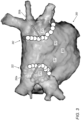
- the anatomical map is provided in the original, non-rotated, coordinate system, and therefore any proposed full ablation line is largely oriented in an oblique angle in space, as seen in Fig. 3 below.
- the algorithm proposes interpolation of the ablation tags to complete a full WACA contour.
- the interpolation may be proposed in regions such as the top and bottom portions of the ablation line, where the posterior and anterior lines approach each other and there is no corresponding posterior tag available.
- the gap between designed ablation tags over which an interpolation can be made is limited to a maximal value in order to verify that interpolation is relying on a sufficient number, and sufficient density, of posterior ablation tags.
- the option to perform interpolation may be available, for example, as a check box in the GUI.
- the physician may, alternatively or additionally to using interpolation, mark any ablation tags deemed missing after the automated WACA planning.
- Fig. 1 is a schematic, pictorial illustration of a catheter-based electroanatomical (EA) mapping and ablation system 10, in accordance with an example of the present disclosure.
- EA electroanatomical
- System 10 includes multiple catheters which are percutaneously inserted by physician 24 through the patient's vascular system into a chamber or vascular structure of a heart 12 (seen in inset 45).
- a delivery sheath catheter is inserted into a cardiac chamber, such as the left or right atrium near a desired location in heart 12.
- a plurality of catheters can be inserted into the delivery sheath catheter so as to arrive at the desired location.
- the plurality of catheters may include a catheter dedicated for pacing, a catheter for sensing intracardiac electrogram signals, a catheter dedicated for ablating and/or a catheter dedicated for both EA mapping and ablating.
- An example catheter 14, illustrated herein, is configured for sensing bipolar electrograms.
- Physician 24 brings a distal tip 28 (also called hereinafter distal end assembly 28) of catheter 14 into contact with the heart wall for sensing a target site in heart 12.
- physician 24 similarly brings a distal end of an ablation catheter to a target site.
- catheter 14 is an exemplary catheter that includes a basket distal end 28, including one, and preferably multiple, electrodes 26 optionally distributed over a plurality of splines 22 at distal tip 28 and configured to sense IEGM signals.
- Catheter 14 may additionally include a position sensor 29 embedded in or near distal tip 28 on a shaft 46 of catheter 14, for tracking its position and orientation of distal tip 28.
- position sensor 29 is a magnetic-based position sensor including three magnetic coils for sensing three-dimensional (3D) position and orientation.
- distal tip 28 further includes an expansion/collapse rod 42 of expandable assembly 28 that is mechanically connected to basket assembly 28 at a distal edge 41 of assembly 28.
- Magnetic based position sensor 29 may be operated together with a location pad 25 that includes a plurality of magnetic coils 32 configured to generate magnetic fields in a predefined working volume. Real-time position of distal tip 28 of catheter 14 may be tracked based on magnetic fields generated with location pad 25 and sensed by magnetic based position sensor 29. Details of the magnetic based position sensing technology are described in U.S. Patent Nos. 5,5391,199 ; 5,443,489 ; 5,558,091 ; 6,172,499 ; 6,239,724 ; 6,332,089 ; 6,484,118 ; 6,618,612 ; 6,690,963 ; 6,788,967 ; 6,892,091 .
- a recorder 11 displays cardiac signals 21 (e.g., electrograms acquired at respectively tracked cardiac tissue positions) acquired with body surface ECG electrodes 18 and intracardiac electrograms acquired with electrodes 26 of catheter 14. Recorder 11 may include pacing capability to pace the heart rhythm, and/or may be electrically connected to a standalone pacer.
- cardiac signals 21 e.g., electrograms acquired at respectively tracked cardiac tissue positions
- intracardiac electrograms acquired with electrodes 26 of catheter 14.
- Recorder 11 may include pacing capability to pace the heart rhythm, and/or may be electrically connected to a standalone pacer.
- System 10 may include an ablation energy generator 50 that is adapted to conduct ablative energy to one or more electrodes at a distal tip of a catheter configured for ablation.
- Energy produced by ablation energy generator 50 may include, but is not limited to, radiofrequency (RF) energy or pulsed-field ablation (PFA) energy, including monopolar or bipolar high-voltage DC pulses, to be used to effect irreversible electroporation (IRE), or combinations thereof.
- RF radiofrequency
- PFA pulsed-field ablation
- IRE irreversible electroporation
- Patient interface unit (PIU) 30 is an interface configured to establish electrical communication between catheters, electrophysiological equipment, power supply and a workstation 55 to control system 10 operation and receive EA signals from the catheter.
- Electrophysiological equipment of system 10 may include, for example, multiple catheters, location pad 25, body surface ECG electrodes 18, electrode patches 38, ablation energy generator 50, and recorder 11.
- PIU 30 additionally includes processing capability for implementing real-time computations of catheter locations and for performing ECG calculations.
- Workstation 55 includes memory 57, a processor 56 unit with memory or storage with appropriate operating software loaded therein, and user interface capability. Workstation 55 may provide multiple functions, optionally including (i) modeling endocardial anatomy in three-dimensions (3D) and rendering the model or anatomical map 20 for display on a display device 27, (ii) displaying on display device 27 activation sequences (or other data) compiled from recorded cardiac signals 21 in representative visual indicia or imagery superimposed on the rendered anatomical map 20, (iii) displaying real-time location and orientation of multiple catheters within the heart chamber, and (iv) displaying sites of interest on display device 27 such as places where ablation energy has been applied.
- One commercial product embodying elements of system 10 is available as the CARTO TM 3 System, available from Biosense Webster, Inc., 31A Technology Drive, Irvine, CA 92618.
- processor 56 runs an algorithm that uses the anterior ablation tag data as markers for locations over the anterior ablation lines, and computes a complimentary posterior design line to aid the user in achieving optimal continuous circumferential ablation.
- processor 56 receives, e.g., via a GUI 111, a user-subjective entry of a minimal distance between anterior and required respective posterior tags and applies the calculations described in Figs 2A and 2B .
- processor 56 typically comprises a general-purpose computer, which is programmed in software to carry out the functions described herein.
- the software may be downloaded to the computer in electronic form, over a network, for example, or it may, alternatively or additionally, be provided and/or stored on non-transitory tangible media, such as magnetic, optical, or electronic memory.
- system 10 is shown by way of example, in order to illustrate certain problems that are addressed by examples of the present disclosure and to demonstrate the application of these examples in enhancing the performance of such a system.
- Examples of the present disclosure are by no means limited to this specific sort of example system, and the principles described herein may similarly be applied to other sorts of medical systems.
- other multi-electrode catheter types may be used, such as the OCTARAY TM catheter or a flat catheter.
- the disclosed algorithm defines an ROI on an anatomical map of a left atrium, the ROI comprising a portion of the inner wall of the left atrium, the portion comprising one of left and right ostia of pulmonary veins.
- the ostia are oriented in some angle in space, the direction defined relative to ostia openings, such as a normal to a landing plane of the ostia.
- the processor uses an application to rotate the ostia orientation to be largely parallel to the coronal axis (i.e., x-axis). After this rotation in space, the entrance planes to ostia Figs.2A and 2B lay within the sagittal y-z plane.
- Figs. 2A and 2B are schematic illustrations of respective ablation tags 215 and 225 along incomplete ablation lines 201 and 221 around right pulmonary vein ostia 222 and around left pulmonary vein ostia 242, respectively, in accordance with an example of the present disclosure.
- Ablation lines 201 and 221 comprise, respectively, anterior ablation line 250a and 250b portions and a yet-to-be-determined posterior portions of ablation lines 251 and 252.
- Anterior ablation tags 215 and 225 are easier to apply based on anatomical landmarks, such as the ridge.
- the disclosed algorithm finds posterior ablation tags 225 and 226 for respective anterior ablation tags 215 and 225.
- the algorithm receives, e.g., via GUI 111, a user-subjective entry request for the desired anatomical distance (210, 212) between an ablation tag on an anterior plane 203 and a respectively required ablation tag on a posterior plane 205.
- anterior and posterior coronal planes such as planes 203 and 205.
- the system may recommend a default minimal distance of 24 millimeters.
- the algorithm computes the shortest distance between the two planes (e.g., 203 and 205) for each ablation tag in the anterior side that intersects the tag position. The distance must be above or equal the minimal distance entered by the user.
- the algorithm does not generate a posterior tag, and, in order to avoid stenosis, may indicate lack of output to the user.
- the algorithm proposes interpolation of the ablation tags into a full contour.
- the interpolation may be performed in limited regions, such as the bottom portions (271, 281) of the ablation line, where a corresponding posterior tag may be determined by the above-described method.
- Fig. 3 is an anatomical map 300 of a left atrium 301 and pulmonary veins superimposed with posterior ablation tags 351 and 352 projected from respective anterior ablation tags 350a and 350b, in accordance with an example of the present disclosure.
- the map shows typically oblique angled ablation lines, wherein arrows 310 and 312 in space are indicated only to illustrate the process of the projection, whereas actual projections are computed in a rotated coordinate system, as described in Figs. 2A and 2B .
- ablation tags seen in Fig. 3 may be a result of manual tagging by the physician, while others may be the result of interpolation, as described above.
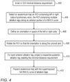
- Fig. 4 is a flow chart that schematically illustrates a method to automatically project, from anterior ablation tags, respective posterior ablation tags, in accordance with an example of the present disclosure.
- the algorithm according to the presented example, carries out a process that begins with physician 24 entering a minimal distance between anterior and posterior ablation tags via GUI 111, at a distance requirement setting step 402.
- the algorithm which the physician may initiate via the same GUI or another GUI of the mapping and ablation system, selects an ROI on an anatomical map of the left atrium, at an ROI selection step 404.
- the ROI is of a map portion of the inner wall of a left atrium related structures and must comprise the aforementioned anterior ablation tags of the right and or left WACA.
- the processor uses the algorithm to define, at an orientation defining step 406, an orientation for the selected ROI, which is usually the normal to a landing plane of the right/left ostia included in the ROI.
- anatomical mapping software applications may include other tools to delineate (and subsequently rotate) an anatomical map or portion thereof in space.
- the processor runs the algorithm (or another software tool) to rotate the ROI such that the ostia landing plane is parallel to the sagittal y-z plane seen in Figs. 2A and 2B (or that the orientation of the normal is parallel to the coronal x-axis as defined above).
- the processor finds, wherever it exists, a posterior ablation tag counterpart of an existing anterior ablation tag. To this end, the processor projects the anterior tag along the sagittal y-axis, and finds a wall tissue target distant by at least the minimal distance required in step 402.
- the processor presents the resulting anatomical map superimposed with a WACA curve that includes the planed posterior ablation line, as seen in Fig. 3 .
- Fig. 4 The flow chart shown in Fig. 4 is chosen purely for the sake of conceptual clarity. Other examples of the technique may comprise different algorithmic steps, such as using a minimal radius from an anterior tag to find the respective posterior tag, instead of using coordinate system rotation. Possible steps, such as graphical ones, are omitted from the disclosure herein purposely in order to provide a more simplified flow chart.
- a method incudes receiving multiple tags (215, 216) along an ablation curve (250a, 250b) that covers a partial circumference (250a, 250b) over an inner wall of a cardiac chamber of a heart (12) of patient.
- the ablation curve (250a, 250b) is completed to a full circumference (201, 221) over the inner wall to eliminate a conduction gap in the ablation curve (201, 221) .
- completing the ablation curve (201, 221) comprises computing, for an existing tag (215, 216), a new tag (225, 226) location while meeting a minimal distance that is required between the new tag (225, 226) and the existing tag (215, 216).
- computing the new tag (225, 226) comprises defining a region of interest (ROI) on an anatomical map of the inner wall, rotating the ROI so a direction of the ROI in space is along a predefined axis of a coordinate system, and calculating a distance (210, 212) between the existing tag (215, 216) and the new tag (225, 226) along an axis orthogonal to the predefined axis.
- ROI region of interest
- the ROI comprises a map (300) portion of the inner wall of a left atrium related structures, the portion comprising one of left or right ostia (222, 242) of pulmonary veins, the direction is defined relative to ostia openings, the predefined axis is a cross-section of coronal and axial planes, and the distance (210, 212) is calculated between anterior and posterior coronal planes (203, 205).
- a system includes a user interface (111) and a processor (56).
- the user interface (111) is configured for receiving multiple tags (215, 216) along an ablation curve (250a, 250b) that covers a partial circumference (250a, 250b) over an inner wall of a cardiac chamber of a heart of patient.
- the processor (56) is configured to, using the tags (215, 216), complete the ablation curve to a full circumference (201, 221) over the inner wall to eliminate a conduction gap in the ablation curve (201, 221).
Landscapes
- Health & Medical Sciences (AREA)
- Engineering & Computer Science (AREA)
- Life Sciences & Earth Sciences (AREA)
- Surgery (AREA)
- General Health & Medical Sciences (AREA)
- Medical Informatics (AREA)
- Molecular Biology (AREA)
- Biomedical Technology (AREA)
- Animal Behavior & Ethology (AREA)
- Physics & Mathematics (AREA)
- Public Health (AREA)
- Heart & Thoracic Surgery (AREA)
- Veterinary Medicine (AREA)
- Nuclear Medicine, Radiotherapy & Molecular Imaging (AREA)
- Theoretical Computer Science (AREA)
- Cardiology (AREA)
- Biophysics (AREA)
- Pathology (AREA)
- Robotics (AREA)
- General Physics & Mathematics (AREA)
- Plasma & Fusion (AREA)
- Otolaryngology (AREA)
- Computer Vision & Pattern Recognition (AREA)
- Human Computer Interaction (AREA)
- Multimedia (AREA)
- Artificial Intelligence (AREA)
- Computing Systems (AREA)
- Evolutionary Computation (AREA)
- Software Systems (AREA)
- Databases & Information Systems (AREA)
- Surgical Instruments (AREA)
Abstract
A method incudes receiving multiple tags along an ablation curve that covers a partial circumference over an inner wall of a cardiac chamber of a heart of patient. Using the tags, the ablation curve is completed to a full circumference over the inner wall to eliminate a conduction gap in the ablation curve.
Description
- This disclosure relates generally to analysis of electroanatomical (EA) signals, and specifically to a system and method for executing automatic segmentation of anatomical structures of wide area circumferential ablation (WACA) points.
- Planning methods of cardiac ablation trajectory over an inner wall of a cardiac chamber were previously proposed in the patent literature. For example,
U.S. Patent Application Publication 2022/036560 describes a method and apparatus for cardiac tissue segmentation using an evaluation engine implemented using a processor coupled to a memory. The evaluation engine receives effective points respective to cardiac tissue of a patient. The evaluation engine determines an anatomical structural classification for each of the effective points based on a structural segmentation for the cardiac tissue and provides the anatomical structural classification with the each of the plurality of effective points to support treatment of the cardiac tissue. - The present disclosure will be more fully understood from the following detailed description of the examples thereof, taken together with the drawings, in which:
-
-
Fig. 1 is a schematic, pictorial illustration of a catheter-based electroanatomical (EA) mapping and ablation system, in accordance with an example of the present disclosure; -
Figs. 2A and 2B are schematic illustrations of ablation tags along incomplete ablation lines around right pulmonary vein ostia and around left pulmonary vein ostia, respectively, in accordance with an example of the present disclosure; -
Fig. 3 is an anatomical map of a left atrium and pulmonary veins superimposed with posterior ablation tags projected from respective anterior ablation tags, in accordance with an example of the present disclosure; and -
Fig. 4 is a flow chart that schematically illustrates a method to automatically project, from anterior ablation tags, respective posterior ablation tags, in accordance with an example of the present disclosure. - Wide Area Circumferential Ablation (WACA) is the standard of care ablation strategy in atrial fibrillation (AFib) cases. Typically, WACA right and left pulmonary vein isolation is performed, point-by-point (the points referred to as WACA ablation points), to create an elliptical (e.g., circular) ring-shaped lesion around the right and left pairs of pulmonary vein ostia.
- However, WACA is limited by an existence of potential conduction gaps in WACA ablation lines (also referred to interchangeably herein as ablation curves). These conduction gaps could lead to pulmonary vein reconnection and recurrent arrhythmia.
- To overcome these limitations, physicians often attempt to estimate WACA ablation point contiguity. However, during a WACA process, physicians encounter technical challenges in ablating a contiguous line in the anterior wall (relying on anatomical markers), as well as continuing and positioning the ablation line to the posterior wall while ensuring sufficient vein patency.
- Examples of the present disclosure that are described herein provide a technique comprising an automated algorithm that uses the anterior ablation tag data to serve as location markers for the anterior ablation lines to compute a complementary posterior design line. This approach aids the user in achieving optimal continuous circumferential ablation. The method relies on the observation that it is easier for a physician to first apply anterior ablation according to the right carina and the left ridge drops.
- In an example implementation, a processor receives a region of interest (ROI) on an anatomical map, the ROI comprising left and/or right pulmonary vein ostia and comprising the aforementioned existing anterior ablation tags. In general, each right and left ostia pair has some general orientation in space, such as defined by a normal to a landing plane fitted to the ostia. The processor rotates the ROI such that it is largely parallel to a coronal x-axis of a common sagittal-coronal-axial (yz-xz-xy) x-y-z derived coordinate system.
- The processor receives, e.g., e.g., via a user interface such as a graphical user interface (GUI) or a prompt line for entering a numerical value, a user-subjective entry request regarding the desired minimal distance between an anterior ablation tag and a respectively required (e.g., designed) posterior ablation tag. This distance is defined between anterior and posterior planes after rotation into the x-y-z coordinate system. A projection from an anterior tag to a posterior wall location to generate a respective posterior tag is seen in
Figs. 2A and 2B below. - For each ablation tag in the anterior side that intersects the tag position, the processor compares the resulting distance between the two coronal planes. If the resulting distance is larger than, or equal to, the minimal distance, the posterior respective tag is approved. By this computation, the processor aims to avoid sub-optimally located ablation, such as a position too close within the vein ostium, which can result in vein stenosis and further complications, such as incomplete ablation.
- The processor adds the required posterior ablation tag to an anatomical map that the physician can view. The anatomical map is provided in the original, non-rotated, coordinate system, and therefore any proposed full ablation line is largely oriented in an oblique angle in space, as seen in
Fig. 3 below. - In some examples, the algorithm proposes interpolation of the ablation tags to complete a full WACA contour. The interpolation may be proposed in regions such as the top and bottom portions of the ablation line, where the posterior and anterior lines approach each other and there is no corresponding posterior tag available. In another example, the gap between designed ablation tags over which an interpolation can be made is limited to a maximal value in order to verify that interpolation is relying on a sufficient number, and sufficient density, of posterior ablation tags. The option to perform interpolation may be available, for example, as a check box in the GUI.
- As the physician is ultimately responsible to fully make a WACA design without conduction gaps, the physician may, alternatively or additionally to using interpolation, mark any ablation tags deemed missing after the automated WACA planning.
-
Fig. 1 is a schematic, pictorial illustration of a catheter-based electroanatomical (EA) mapping andablation system 10, in accordance with an example of the present disclosure. -
System 10 includes multiple catheters which are percutaneously inserted byphysician 24 through the patient's vascular system into a chamber or vascular structure of a heart 12 (seen in inset 45). Typically, a delivery sheath catheter is inserted into a cardiac chamber, such as the left or right atrium near a desired location inheart 12. Thereafter, a plurality of catheters can be inserted into the delivery sheath catheter so as to arrive at the desired location. The plurality of catheters may include a catheter dedicated for pacing, a catheter for sensing intracardiac electrogram signals, a catheter dedicated for ablating and/or a catheter dedicated for both EA mapping and ablating. Anexample catheter 14, illustrated herein, is configured for sensing bipolar electrograms.Physician 24 brings a distal tip 28 (also called hereinafter distal end assembly 28) ofcatheter 14 into contact with the heart wall for sensing a target site inheart 12. For ablation,physician 24 similarly brings a distal end of an ablation catheter to a target site. - As seen in
inset 65,catheter 14 is an exemplary catheter that includes a basketdistal end 28, including one, and preferably multiple,electrodes 26 optionally distributed over a plurality ofsplines 22 atdistal tip 28 and configured to sense IEGM signals.Catheter 14 may additionally include aposition sensor 29 embedded in or neardistal tip 28 on ashaft 46 ofcatheter 14, for tracking its position and orientation ofdistal tip 28. Optionally, and preferably,position sensor 29 is a magnetic-based position sensor including three magnetic coils for sensing three-dimensional (3D) position and orientation. As seen,distal tip 28 further includes an expansion/collapse rod 42 ofexpandable assembly 28 that is mechanically connected tobasket assembly 28 at adistal edge 41 ofassembly 28. - Magnetic based
position sensor 29 may be operated together with alocation pad 25 that includes a plurality ofmagnetic coils 32 configured to generate magnetic fields in a predefined working volume. Real-time position ofdistal tip 28 ofcatheter 14 may be tracked based on magnetic fields generated withlocation pad 25 and sensed by magnetic basedposition sensor 29. Details of the magnetic based position sensing technology are described inU.S. Patent Nos. 5,5391,199 5,443,489 ;5,558,091 ;6,172,499 ;6,239,724 ;6,332,089 ;6,484,118 ;6,618,612 ;6,690,963 ;6,788,967 ;6,892,091 . -
System 10 includes one ormore electrode patches 38 positioned for skin contact onpatient 23 to establish a location reference forlocation pad 25 as well as impedance-based tracking ofelectrodes 26. For impedance-based tracking, electrical current is directed towardelectrodes 26 and sensed atelectrode skin patches 38 so that the location of each electrode can be triangulated viaelectrode patches 38. Details of the impedance-based location tracking technology are described inUS Patent Nos. 7,536,218 ;7,756,576 ;7,848,787 ;7,869,865 ; and8,456,182 . - A
recorder 11 displays cardiac signals 21 (e.g., electrograms acquired at respectively tracked cardiac tissue positions) acquired with bodysurface ECG electrodes 18 and intracardiac electrograms acquired withelectrodes 26 ofcatheter 14.Recorder 11 may include pacing capability to pace the heart rhythm, and/or may be electrically connected to a standalone pacer. -
System 10 may include anablation energy generator 50 that is adapted to conduct ablative energy to one or more electrodes at a distal tip of a catheter configured for ablation. Energy produced byablation energy generator 50 may include, but is not limited to, radiofrequency (RF) energy or pulsed-field ablation (PFA) energy, including monopolar or bipolar high-voltage DC pulses, to be used to effect irreversible electroporation (IRE), or combinations thereof. - Patient interface unit (PIU) 30 is an interface configured to establish electrical communication between catheters, electrophysiological equipment, power supply and a
workstation 55 to controlsystem 10 operation and receive EA signals from the catheter. Electrophysiological equipment ofsystem 10 may include, for example, multiple catheters,location pad 25, bodysurface ECG electrodes 18,electrode patches 38,ablation energy generator 50, andrecorder 11. Optionally, and preferably,PIU 30 additionally includes processing capability for implementing real-time computations of catheter locations and for performing ECG calculations. -
Workstation 55 includesmemory 57, aprocessor 56 unit with memory or storage with appropriate operating software loaded therein, and user interface capability.Workstation 55 may provide multiple functions, optionally including (i) modeling endocardial anatomy in three-dimensions (3D) and rendering the model oranatomical map 20 for display on adisplay device 27, (ii) displaying ondisplay device 27 activation sequences (or other data) compiled from recordedcardiac signals 21 in representative visual indicia or imagery superimposed on the renderedanatomical map 20, (iii) displaying real-time location and orientation of multiple catheters within the heart chamber, and (iv) displaying sites of interest ondisplay device 27 such as places where ablation energy has been applied. One commercial product embodying elements ofsystem 10 is available as the CARTO™ 3 System, available from Biosense Webster, Inc., 31A Technology Drive, Irvine, CA 92618. - In a disclosed example,
processor 56 runs an algorithm that uses the anterior ablation tag data as markers for locations over the anterior ablation lines, and computes a complimentary posterior design line to aid the user in achieving optimal continuous circumferential ablation. To thisend processor 56 receives, e.g., via aGUI 111, a user-subjective entry of a minimal distance between anterior and required respective posterior tags and applies the calculations described inFigs 2A and 2B . - In some examples,
processor 56 typically comprises a general-purpose computer, which is programmed in software to carry out the functions described herein. The software may be downloaded to the computer in electronic form, over a network, for example, or it may, alternatively or additionally, be provided and/or stored on non-transitory tangible media, such as magnetic, optical, or electronic memory. - This configuration of
system 10 is shown by way of example, in order to illustrate certain problems that are addressed by examples of the present disclosure and to demonstrate the application of these examples in enhancing the performance of such a system. Examples of the present disclosure, however, are by no means limited to this specific sort of example system, and the principles described herein may similarly be applied to other sorts of medical systems. For example, other multi-electrode catheter types may be used, such as the OCTARAY™ catheter or a flat catheter. - As noted above, in one example, the disclosed algorithm defines an ROI on an anatomical map of a left atrium, the ROI comprising a portion of the inner wall of the left atrium, the portion comprising one of left and right ostia of pulmonary veins. In general, the ostia are oriented in some angle in space, the direction defined relative to ostia openings, such as a normal to a landing plane of the ostia. The processor uses an application to rotate the ostia orientation to be largely parallel to the coronal axis (i.e., x-axis). After this rotation in space, the entrance planes to ostia
Figs.2A and 2B lay within the sagittal y-z plane. -
Figs. 2A and 2B are schematic illustrations ofrespective ablation tags incomplete ablation lines Ablation lines anterior ablation line ablation lines - Anterior ablation tags 215 and 225 are easier to apply based on anatomical landmarks, such as the ridge. The disclosed algorithm finds posterior ablation tags 225 and 226 for respective anterior ablation tags 215 and 225. To this end, the algorithm receives, e.g., via
GUI 111, a user-subjective entry request for the desired anatomical distance (210, 212) between an ablation tag on ananterior plane 203 and a respectively required ablation tag on aposterior plane 205. - The aforementioned minimal distance sought between anterior and respective posterior ablation tags is also defined between anterior and posterior coronal planes, such as
planes - To generate a posterior ablation tag, the algorithm computes the shortest distance between the two planes (e.g., 203 and 205) for each ablation tag in the anterior side that intersects the tag position. The distance must be above or equal the minimal distance entered by the user.
- In the event that
distance 210 between the anterior andposterior planes - In some examples, the algorithm proposes interpolation of the ablation tags into a full contour. The interpolation may be performed in limited regions, such as the bottom portions (271, 281) of the ablation line, where a corresponding posterior tag may be determined by the above-described method.
-
Fig. 3 is ananatomical map 300 of aleft atrium 301 and pulmonary veins superimposed with posterior ablation tags 351 and 352 projected from respectiveanterior ablation tags - The map shows typically oblique angled ablation lines, wherein
arrows Figs. 2A and 2B . - In addition, some of the ablation tags seen in
Fig. 3 may be a result of manual tagging by the physician, while others may be the result of interpolation, as described above. -
Fig. 4 is a flow chart that schematically illustrates a method to automatically project, from anterior ablation tags, respective posterior ablation tags, in accordance with an example of the present disclosure. The algorithm, according to the presented example, carries out a process that begins withphysician 24 entering a minimal distance between anterior and posterior ablation tags viaGUI 111, at a distancerequirement setting step 402. - Next, the algorithm, which the physician may initiate via the same GUI or another GUI of the mapping and ablation system, selects an ROI on an anatomical map of the left atrium, at an
ROI selection step 404. The ROI is of a map portion of the inner wall of a left atrium related structures and must comprise the aforementioned anterior ablation tags of the right and or left WACA. - The processor uses the algorithm to define, at an
orientation defining step 406, an orientation for the selected ROI, which is usually the normal to a landing plane of the right/left ostia included in the ROI. However, the anatomical mapping software applications may include other tools to delineate (and subsequently rotate) an anatomical map or portion thereof in space. - At
ROI rotation step 408, the processor runs the algorithm (or another software tool) to rotate the ROI such that the ostia landing plane is parallel to the sagittal y-z plane seen inFigs. 2A and 2B (or that the orientation of the normal is parallel to the coronal x-axis as defined above). - At ablation
tag projection step 410, the processor finds, wherever it exists, a posterior ablation tag counterpart of an existing anterior ablation tag. To this end, the processor projects the anterior tag along the sagittal y-axis, and finds a wall tissue target distant by at least the minimal distance required instep 402. - Finally, at presenting
step 412, the processor presents the resulting anatomical map superimposed with a WACA curve that includes the planed posterior ablation line, as seen inFig. 3 . - The flow chart shown in
Fig. 4 is chosen purely for the sake of conceptual clarity. Other examples of the technique may comprise different algorithmic steps, such as using a minimal radius from an anterior tag to find the respective posterior tag, instead of using coordinate system rotation. Possible steps, such as graphical ones, are omitted from the disclosure herein purposely in order to provide a more simplified flow chart. - A method incudes receiving multiple tags (215, 216) along an ablation curve (250a, 250b) that covers a partial circumference (250a, 250b) over an inner wall of a cardiac chamber of a heart (12) of patient. Using the tags (215, 216), the ablation curve (250a, 250b) is completed to a full circumference (201, 221) over the inner wall to eliminate a conduction gap in the ablation curve (201, 221) .
- The method according to example 1, wherein completing the ablation curve (201, 221) comprises computing, for an existing tag (215, 216), a new tag (225, 226) location while meeting a minimal distance that is required between the new tag (225, 226) and the existing tag (215, 216).
- The method according to any of examples 1 and 2, wherein computing the new tag (225, 226) comprises defining a region of interest (ROI) on an anatomical map of the inner wall, rotating the ROI so a direction of the ROI in space is along a predefined axis of a coordinate system, and calculating a distance (210, 212) between the existing tag (215, 216) and the new tag (225, 226) along an axis orthogonal to the predefined axis.
- The method according to any of examples 1 through 3, wherein the ROI comprises a map (300) portion of the inner wall of a left atrium related structures, the portion comprising one of left or right ostia (222, 242) of pulmonary veins, the direction is defined relative to ostia openings, the predefined axis is a cross-section of coronal and axial planes, and the distance (210, 212) is calculated between anterior and posterior coronal planes (203, 205).
- The method according to any of examples 1 and 2, and comprising overlaying the new tag (225, 226) over an anatomical map (300) of the cardiac chamber.
- The method according to any of examples 1 and 2, wherein the partial circumference of the ablation curve (201, 221) covers an anterior portion (250a, 250b) of the inner wall of a left atrium, and wherein completing the ablation curve comprises computing a remaining portion (251, 252) the ablation curve over a posterior portion of the inner wall of the left atrium.
- The method according to any of examples 1 through 6, wherein the full circumference encircles at least one of the pairs of superior and inferior left pulmonary veins and superior and inferior right pulmonary veins.
- The method according to example 1, wherein completing the ablation curve (250a, 250b) comprises generating a Wide Area Circumferential Ablation (WACA) curve.
- A system includes a user interface (111) and a processor (56). The user interface (111) is configured for receiving multiple tags (215, 216) along an ablation curve (250a, 250b) that covers a partial circumference (250a, 250b) over an inner wall of a cardiac chamber of a heart of patient. The processor (56) is configured to, using the tags (215, 216), complete the ablation curve to a full circumference (201, 221) over the inner wall to eliminate a conduction gap in the ablation curve (201, 221).
- Although the examples described herein mainly address cardiac diagnostic applications, the methods and systems described herein can also be used in other medical applications.
- It will be appreciated that the examples described above are cited by way of example, and that the present disclosure is not limited to what has been particularly shown and described hereinabove. Rather, the scope of the present disclosure includes both combinations and subcombinations of the various features described hereinabove, as well as variations and modifications thereof which would occur to persons skilled in the art upon reading the foregoing description and which are not disclosed in the prior art.
Claims (15)
- A method, comprising:receiving multiple tags (215, 216) along an ablation curve (250a, 250b) that covers a partial circumference (250a, 250b) over an inner wall of a cardiac chamber of a heart (12) of patient; andusing the tags (215, 216), completing the ablation curve (250a, 250b) to a full circumference (201, 221) over the inner wall to eliminate a conduction gap in the ablation curve (201, 221).
- The method according to claim 1, wherein completing the ablation curve (201, 221) comprises computing, for an existing tag (215, 216), a new tag (225, 226) location while meeting a minimal distance that is required between the new tag (225, 226) and the existing tag (215, 216).
- The method according to claim 2, wherein computing the new tag (225, 226) comprises defining a region of interest (ROI) on an anatomical map of the inner wall, rotating the ROI so a direction of the ROI in space is along a predefined axis of a coordinate system, and calculating a distance (210, 212) between the existing tag (215, 216) and the new tag (225, 226) along an axis orthogonal to the predefined axis.
- The method according to claim 3, wherein the ROI comprises a map (300) portion of the inner wall of a left atrium related structures, the portion comprising one of left or right ostia (222, 242) of pulmonary veins, the direction is defined relative to ostia openings, the predefined axis is a cross-section of coronal and axial planes, and the distance (210, 212) is calculated between anterior and posterior coronal planes (203, 205).
- The method according to claim 2, and comprising overlaying the new tag (225, 226) over an anatomical map (300) of the cardiac chamber.
- The method according to claim 1, wherein the partial circumference of the ablation curve (201, 221) covers an anterior portion (250a, 250b) of the inner wall of a left atrium, and wherein completing the ablation curve comprises computing a remaining portion (251, 252) the ablation curve over a posterior portion of the inner wall of the left atrium.
- The method according to claim 1, wherein completing the ablation curve (250a, 250b) comprises generating a Wide Area Circumferential Ablation (WACA) curve.
- A system, comprising:a user interface (111) configured for receiving multiple tags (215, 216) along an ablation curve (250a, 250b) that covers a partial circumference (250a, 250b) over an inner wall of a cardiac chamber of a heart of patient; anda processor (56), which is configured to, using the tags (215, 216), complete the ablation curve to a full circumference (201, 221) over the inner wall to eliminate a conduction gap in the ablation curve (201, 221).
- The system according to claim 8, wherein completing the ablation curve (201, 221) comprises computing, for an existing tag (215, 216), a new tag (225, 226) location while meeting a minimal distance that is required between the new tag (225, 226) and the existing tag (215, 216).
- The system according to claim 9, wherein the processor is configured to compute the new tag (225, 226) by defining a region of interest (ROI) on an anatomical map of the inner wall, rotating the ROI so a direction of the ROI in space is along a predefined axis of a coordinate system, and calculating a distance (210, 212) between the existing tag (215, 216) and the new tag (225, 226) along an axis orthogonal to the predefined axis.
- The system according to claim 10, wherein the ROI comprises a map (300) portion of the inner wall of a left atrium related structures, the portion comprising one of left or right ostia (222, 242) of pulmonary veins, the direction is defined relative to ostia openings, the predefined axis is a cross-section of coronal and axial planes, and the distance (210, 212) is calculated between anterior and posterior coronal planes (203, 205).
- The system according to claim 9, the processor is further configured to overlay the new tag (225, 226) over an anatomical map (300) of the cardiac chamber.
- The system according to claim 8, wherein the partial circumference of the ablation curve (201, 221) covers an anterior portion (250a, 250b) of the inner wall of a left atrium, and wherein completing the ablation curve comprises computing a remaining portion (251, 252) the ablation curve over a posterior portion of the inner wall of the left atrium.
- The method according to claim 6 or the system according to claim 13, wherein the full circumference encircles at least one of the pairs of superior and inferior left pulmonary veins and superior and inferior right pulmonary veins.
- The system according to claim 8, wherein the processor is configured to complete the ablation curve (250a, 250b) by generating a Wide Area Circumferential Ablation (WACA) curve.
Applications Claiming Priority (1)
| Application Number | Priority Date | Filing Date | Title |
|---|---|---|---|
| US18/204,098 US12446963B2 (en) | 2023-05-31 | 2023-05-31 | Automatic projection of a cardiac chamber posterior wall ablation line |
Publications (1)
| Publication Number | Publication Date |
|---|---|
| EP4470495A1 true EP4470495A1 (en) | 2024-12-04 |
Family
ID=91334088
Family Applications (1)
| Application Number | Title | Priority Date | Filing Date |
|---|---|---|---|
| EP24178963.5A Pending EP4470495A1 (en) | 2023-05-31 | 2024-05-30 | Automatic projection of a cardiac chamber posterior wall ablation line |
Country Status (5)
| Country | Link |
|---|---|
| US (1) | US12446963B2 (en) |
| EP (1) | EP4470495A1 (en) |
| JP (1) | JP2024173794A (en) |
| CN (1) | CN119055346A (en) |
| IL (1) | IL312950A (en) |
Citations (18)
| Publication number | Priority date | Publication date | Assignee | Title |
|---|---|---|---|---|
| US5391199A (en) | 1993-07-20 | 1995-02-21 | Biosense, Inc. | Apparatus and method for treating cardiac arrhythmias |
| US5558091A (en) | 1993-10-06 | 1996-09-24 | Biosense, Inc. | Magnetic determination of position and orientation |
| US6172499B1 (en) | 1999-10-29 | 2001-01-09 | Ascension Technology Corporation | Eddy current error-reduced AC magnetic position measurement system |
| US6239724B1 (en) | 1997-12-30 | 2001-05-29 | Remon Medical Technologies, Ltd. | System and method for telemetrically providing intrabody spatial position |
| US6332089B1 (en) | 1996-02-15 | 2001-12-18 | Biosense, Inc. | Medical procedures and apparatus using intrabody probes |
| US6484118B1 (en) | 2000-07-20 | 2002-11-19 | Biosense, Inc. | Electromagnetic position single axis system |
| US6618612B1 (en) | 1996-02-15 | 2003-09-09 | Biosense, Inc. | Independently positionable transducers for location system |
| US6690963B2 (en) | 1995-01-24 | 2004-02-10 | Biosense, Inc. | System for determining the location and orientation of an invasive medical instrument |
| US6892091B1 (en) | 2000-02-18 | 2005-05-10 | Biosense, Inc. | Catheter, method and apparatus for generating an electrical map of a chamber of the heart |
| US7536218B2 (en) | 2005-07-15 | 2009-05-19 | Biosense Webster, Inc. | Hybrid magnetic-based and impedance-based position sensing |
| US7756576B2 (en) | 2005-08-26 | 2010-07-13 | Biosense Webster, Inc. | Position sensing and detection of skin impedance |
| US7848787B2 (en) | 2005-07-08 | 2010-12-07 | Biosense Webster, Inc. | Relative impedance measurement |
| US7869865B2 (en) | 2005-01-07 | 2011-01-11 | Biosense Webster, Inc. | Current-based position sensing |
| US8456182B2 (en) | 2008-09-30 | 2013-06-04 | Biosense Webster, Inc. | Current localization tracker |
| US20170128128A1 (en) * | 2015-11-06 | 2017-05-11 | Biosense Webster (Israel) Ltd. | Pulmonary vein isolation gap finder |
| US20200352652A1 (en) * | 2019-05-06 | 2020-11-12 | Biosense Webster (Israel) Ltd. | Systems and methods for improving cardiac ablation procedures |
| US20220036560A1 (en) | 2020-07-30 | 2022-02-03 | Biosense Webster (Israel) Ltd. | Automatic segmentation of anatomical structures of wide area circumferential ablation points |
| US20220225924A1 (en) * | 2021-01-19 | 2022-07-21 | Biosense Webster (Israel) Ltd. | Automatic mesh reshaping of an anatomical map to expose internal points of interest |
Family Cites Families (6)
| Publication number | Priority date | Publication date | Assignee | Title |
|---|---|---|---|---|
| US9205279B2 (en) | 2009-07-17 | 2015-12-08 | Cyberheart, Inc. | Heart tissue surface contour-based radiosurgical treatment planning |
| US10354758B2 (en) | 2014-08-28 | 2019-07-16 | Siemens Healthcare Gmbh | System and method for patient-specific image-based simulation of atrial electrophysiology |
| US11039888B2 (en) * | 2015-05-12 | 2021-06-22 | Navix International Limited | Calculation of an ablation plan |
| US11622713B2 (en) * | 2016-11-16 | 2023-04-11 | Navix International Limited | Estimators for ablation effectiveness |
| US20220005198A1 (en) * | 2020-07-06 | 2022-01-06 | Biosense Webster (Israel) Ltd. | Automatic contiguity estimation of wide area circumferential ablation points |
| WO2022182876A1 (en) | 2021-02-25 | 2022-09-01 | University Of Utah Research Foundation | Treatment planning for atrial fibrillation using patient-specific models based on quantification of fibrillatory area |
-
2023
- 2023-05-31 US US18/204,098 patent/US12446963B2/en active Active
-
2024
- 2024-05-19 IL IL312950A patent/IL312950A/en unknown
- 2024-05-30 JP JP2024087781A patent/JP2024173794A/en active Pending
- 2024-05-30 EP EP24178963.5A patent/EP4470495A1/en active Pending
- 2024-05-31 CN CN202410693821.1A patent/CN119055346A/en active Pending
Patent Citations (20)
| Publication number | Priority date | Publication date | Assignee | Title |
|---|---|---|---|---|
| US5443489A (en) | 1993-07-20 | 1995-08-22 | Biosense, Inc. | Apparatus and method for ablation |
| US5391199A (en) | 1993-07-20 | 1995-02-21 | Biosense, Inc. | Apparatus and method for treating cardiac arrhythmias |
| US5558091A (en) | 1993-10-06 | 1996-09-24 | Biosense, Inc. | Magnetic determination of position and orientation |
| US6690963B2 (en) | 1995-01-24 | 2004-02-10 | Biosense, Inc. | System for determining the location and orientation of an invasive medical instrument |
| US6332089B1 (en) | 1996-02-15 | 2001-12-18 | Biosense, Inc. | Medical procedures and apparatus using intrabody probes |
| US6618612B1 (en) | 1996-02-15 | 2003-09-09 | Biosense, Inc. | Independently positionable transducers for location system |
| US6788967B2 (en) | 1997-05-14 | 2004-09-07 | Biosense, Inc. | Medical diagnosis, treatment and imaging systems |
| US6239724B1 (en) | 1997-12-30 | 2001-05-29 | Remon Medical Technologies, Ltd. | System and method for telemetrically providing intrabody spatial position |
| US6172499B1 (en) | 1999-10-29 | 2001-01-09 | Ascension Technology Corporation | Eddy current error-reduced AC magnetic position measurement system |
| US6892091B1 (en) | 2000-02-18 | 2005-05-10 | Biosense, Inc. | Catheter, method and apparatus for generating an electrical map of a chamber of the heart |
| US6484118B1 (en) | 2000-07-20 | 2002-11-19 | Biosense, Inc. | Electromagnetic position single axis system |
| US7869865B2 (en) | 2005-01-07 | 2011-01-11 | Biosense Webster, Inc. | Current-based position sensing |
| US7848787B2 (en) | 2005-07-08 | 2010-12-07 | Biosense Webster, Inc. | Relative impedance measurement |
| US7536218B2 (en) | 2005-07-15 | 2009-05-19 | Biosense Webster, Inc. | Hybrid magnetic-based and impedance-based position sensing |
| US7756576B2 (en) | 2005-08-26 | 2010-07-13 | Biosense Webster, Inc. | Position sensing and detection of skin impedance |
| US8456182B2 (en) | 2008-09-30 | 2013-06-04 | Biosense Webster, Inc. | Current localization tracker |
| US20170128128A1 (en) * | 2015-11-06 | 2017-05-11 | Biosense Webster (Israel) Ltd. | Pulmonary vein isolation gap finder |
| US20200352652A1 (en) * | 2019-05-06 | 2020-11-12 | Biosense Webster (Israel) Ltd. | Systems and methods for improving cardiac ablation procedures |
| US20220036560A1 (en) | 2020-07-30 | 2022-02-03 | Biosense Webster (Israel) Ltd. | Automatic segmentation of anatomical structures of wide area circumferential ablation points |
| US20220225924A1 (en) * | 2021-01-19 | 2022-07-21 | Biosense Webster (Israel) Ltd. | Automatic mesh reshaping of an anatomical map to expose internal points of interest |
Also Published As
| Publication number | Publication date |
|---|---|
| JP2024173794A (en) | 2024-12-12 |
| CN119055346A (en) | 2024-12-03 |
| US20240398477A1 (en) | 2024-12-05 |
| IL312950A (en) | 2024-12-01 |
| US12446963B2 (en) | 2025-10-21 |
Similar Documents
| Publication | Publication Date | Title |
|---|---|---|
| US12268413B2 (en) | Recommending transseptal needle curvature based on anatomy | |
| EP4608310A1 (en) | Alignment aid for ablation procedures | |
| US12446963B2 (en) | Automatic projection of a cardiac chamber posterior wall ablation line | |
| EP4494561A1 (en) | Estimation and visualization of electroanatomical (ea) analysis quality of an ea map | |
| US20250352261A1 (en) | Ablation location prediction over anatomical maps | |
| EP4389004B1 (en) | Detecting local activation source in atrial fibrillation | |
| US20250375245A1 (en) | Ablation tags indicator | |
| US12414729B2 (en) | Focal arrhythmia source finder using directed graphs | |
| EP4699529A1 (en) | Catheter depth perception tools on map | |
| EP4545035A1 (en) | Graphically encoded ablation tags according to regions of anatomy | |
| US20250241715A1 (en) | Gui to display locations of early and late local activation times (lat) in lat map and correct the map | |
| EP4679364A1 (en) | Methods and systems for identifying conduction flow paths in anatomical maps | |
| EP4632755A1 (en) | Mapping a cavity | |
| US20240203079A1 (en) | Automatic editing of electroanatomical maps | |
| US20250344986A1 (en) | Cardiac map dimming with gui | |
| US20250025129A1 (en) | Visualization of distal end effector on biplane or triplane views using intracardiac echography (ice) | |
| US20250345004A1 (en) | Ventricular tachycardia (vt) target identification by selective pacing |
Legal Events
| Date | Code | Title | Description |
|---|---|---|---|
| PUAI | Public reference made under article 153(3) epc to a published international application that has entered the european phase |
Free format text: ORIGINAL CODE: 0009012 |
|
| STAA | Information on the status of an ep patent application or granted ep patent |
Free format text: STATUS: THE APPLICATION HAS BEEN PUBLISHED |
|
| AK | Designated contracting states |
Kind code of ref document: A1 Designated state(s): AL AT BE BG CH CY CZ DE DK EE ES FI FR GB GR HR HU IE IS IT LI LT LU LV MC ME MK MT NL NO PL PT RO RS SE SI SK SM TR |
|
| STAA | Information on the status of an ep patent application or granted ep patent |
Free format text: STATUS: REQUEST FOR EXAMINATION WAS MADE |
|
| 17P | Request for examination filed |
Effective date: 20250529 |
|
| STAA | Information on the status of an ep patent application or granted ep patent |
Free format text: STATUS: EXAMINATION IS IN PROGRESS |