EP4470460A2 - Wound therapy system with wound volume estimation - Google Patents
Wound therapy system with wound volume estimation Download PDFInfo
- Publication number
- EP4470460A2 EP4470460A2 EP24207849.1A EP24207849A EP4470460A2 EP 4470460 A2 EP4470460 A2 EP 4470460A2 EP 24207849 A EP24207849 A EP 24207849A EP 4470460 A2 EP4470460 A2 EP 4470460A2
- Authority
- EP
- European Patent Office
- Prior art keywords
- wound
- negative pressure
- controller
- drawdown
- volume
- Prior art date
- Legal status (The legal status is an assumption and is not a legal conclusion. Google has not performed a legal analysis and makes no representation as to the accuracy of the status listed.)
- Pending
Links
Images







Classifications
-
- A—HUMAN NECESSITIES
- A61—MEDICAL OR VETERINARY SCIENCE; HYGIENE
- A61B—DIAGNOSIS; SURGERY; IDENTIFICATION
- A61B5/00—Measuring for diagnostic purposes; Identification of persons
- A61B5/103—Measuring devices for testing the shape, pattern, colour, size or movement of the body or parts thereof, for diagnostic purposes
- A61B5/107—Measuring physical dimensions, e.g. size of the entire body or parts thereof
- A61B5/1072—Measuring physical dimensions, e.g. size of the entire body or parts thereof measuring distances on the body, e.g. measuring length, height or thickness
-
- A—HUMAN NECESSITIES
- A61—MEDICAL OR VETERINARY SCIENCE; HYGIENE
- A61B—DIAGNOSIS; SURGERY; IDENTIFICATION
- A61B5/00—Measuring for diagnostic purposes; Identification of persons
- A61B5/44—Detecting, measuring or recording for evaluating the integumentary system, e.g. skin, hair or nails
- A61B5/441—Skin evaluation, e.g. for skin disorder diagnosis
- A61B5/445—Evaluating skin irritation or skin trauma, e.g. rash, eczema, wound, bed sore
-
- A—HUMAN NECESSITIES
- A61—MEDICAL OR VETERINARY SCIENCE; HYGIENE
- A61B—DIAGNOSIS; SURGERY; IDENTIFICATION
- A61B5/00—Measuring for diagnostic purposes; Identification of persons
- A61B5/48—Other medical applications
- A61B5/4836—Diagnosis combined with treatment in closed-loop systems or methods
-
- A—HUMAN NECESSITIES
- A61—MEDICAL OR VETERINARY SCIENCE; HYGIENE
- A61B—DIAGNOSIS; SURGERY; IDENTIFICATION
- A61B5/00—Measuring for diagnostic purposes; Identification of persons
- A61B5/72—Signal processing specially adapted for physiological signals or for diagnostic purposes
- A61B5/7235—Details of waveform analysis
- A61B5/7264—Classification of physiological signals or data, e.g. using neural networks, statistical classifiers, expert systems or fuzzy systems
-
- A—HUMAN NECESSITIES
- A61—MEDICAL OR VETERINARY SCIENCE; HYGIENE
- A61B—DIAGNOSIS; SURGERY; IDENTIFICATION
- A61B5/00—Measuring for diagnostic purposes; Identification of persons
- A61B5/72—Signal processing specially adapted for physiological signals or for diagnostic purposes
- A61B5/7271—Specific aspects of physiological measurement analysis
- A61B5/7278—Artificial waveform generation or derivation, e.g. synthesizing signals from measured signals
-
- A—HUMAN NECESSITIES
- A61—MEDICAL OR VETERINARY SCIENCE; HYGIENE
- A61B—DIAGNOSIS; SURGERY; IDENTIFICATION
- A61B5/00—Measuring for diagnostic purposes; Identification of persons
- A61B5/74—Details of notification to user or communication with user or patient; User input means
- A61B5/7465—Arrangements for interactive communication between patient and care services, e.g. by using a telephone network
- A61B5/747—Arrangements for interactive communication between patient and care services, e.g. by using a telephone network in case of emergency, i.e. alerting emergency services
-
- A—HUMAN NECESSITIES
- A61—MEDICAL OR VETERINARY SCIENCE; HYGIENE
- A61M—DEVICES FOR INTRODUCING MEDIA INTO, OR ONTO, THE BODY; DEVICES FOR TRANSDUCING BODY MEDIA OR FOR TAKING MEDIA FROM THE BODY; DEVICES FOR PRODUCING OR ENDING SLEEP OR STUPOR
- A61M1/00—Suction or pumping devices for medical purposes; Devices for carrying-off, for treatment of, or for carrying-over, body-liquids; Drainage systems
- A61M1/71—Suction drainage systems
- A61M1/73—Suction drainage systems comprising sensors or indicators for physical values
-
- A—HUMAN NECESSITIES
- A61—MEDICAL OR VETERINARY SCIENCE; HYGIENE
- A61M—DEVICES FOR INTRODUCING MEDIA INTO, OR ONTO, THE BODY; DEVICES FOR TRANSDUCING BODY MEDIA OR FOR TAKING MEDIA FROM THE BODY; DEVICES FOR PRODUCING OR ENDING SLEEP OR STUPOR
- A61M1/00—Suction or pumping devices for medical purposes; Devices for carrying-off, for treatment of, or for carrying-over, body-liquids; Drainage systems
- A61M1/71—Suction drainage systems
- A61M1/74—Suction control
- A61M1/742—Suction control by changing the size of a vent
-
- A—HUMAN NECESSITIES
- A61—MEDICAL OR VETERINARY SCIENCE; HYGIENE
- A61M—DEVICES FOR INTRODUCING MEDIA INTO, OR ONTO, THE BODY; DEVICES FOR TRANSDUCING BODY MEDIA OR FOR TAKING MEDIA FROM THE BODY; DEVICES FOR PRODUCING OR ENDING SLEEP OR STUPOR
- A61M1/00—Suction or pumping devices for medical purposes; Devices for carrying-off, for treatment of, or for carrying-over, body-liquids; Drainage systems
- A61M1/90—Negative pressure wound therapy devices, i.e. devices for applying suction to a wound to promote healing, e.g. including a vacuum dressing
- A61M1/96—Suction control thereof
- A61M1/964—Suction control thereof having venting means on or near the dressing
-
- A—HUMAN NECESSITIES
- A61—MEDICAL OR VETERINARY SCIENCE; HYGIENE
- A61M—DEVICES FOR INTRODUCING MEDIA INTO, OR ONTO, THE BODY; DEVICES FOR TRANSDUCING BODY MEDIA OR FOR TAKING MEDIA FROM THE BODY; DEVICES FOR PRODUCING OR ENDING SLEEP OR STUPOR
- A61M1/00—Suction or pumping devices for medical purposes; Devices for carrying-off, for treatment of, or for carrying-over, body-liquids; Drainage systems
- A61M1/90—Negative pressure wound therapy devices, i.e. devices for applying suction to a wound to promote healing, e.g. including a vacuum dressing
- A61M1/96—Suction control thereof
- A61M1/966—Suction control thereof having a pressure sensor on or near the dressing
-
- A—HUMAN NECESSITIES
- A61—MEDICAL OR VETERINARY SCIENCE; HYGIENE
- A61B—DIAGNOSIS; SURGERY; IDENTIFICATION
- A61B2562/00—Details of sensors; Constructional details of sensor housings or probes; Accessories for sensors
- A61B2562/02—Details of sensors specially adapted for in-vivo measurements
- A61B2562/0247—Pressure sensors
-
- A—HUMAN NECESSITIES
- A61—MEDICAL OR VETERINARY SCIENCE; HYGIENE
- A61M—DEVICES FOR INTRODUCING MEDIA INTO, OR ONTO, THE BODY; DEVICES FOR TRANSDUCING BODY MEDIA OR FOR TAKING MEDIA FROM THE BODY; DEVICES FOR PRODUCING OR ENDING SLEEP OR STUPOR
- A61M1/00—Suction or pumping devices for medical purposes; Devices for carrying-off, for treatment of, or for carrying-over, body-liquids; Drainage systems
- A61M1/71—Suction drainage systems
- A61M1/77—Suction-irrigation systems
-
- A—HUMAN NECESSITIES
- A61—MEDICAL OR VETERINARY SCIENCE; HYGIENE
- A61M—DEVICES FOR INTRODUCING MEDIA INTO, OR ONTO, THE BODY; DEVICES FOR TRANSDUCING BODY MEDIA OR FOR TAKING MEDIA FROM THE BODY; DEVICES FOR PRODUCING OR ENDING SLEEP OR STUPOR
- A61M1/00—Suction or pumping devices for medical purposes; Devices for carrying-off, for treatment of, or for carrying-over, body-liquids; Drainage systems
- A61M1/84—Drainage tubes; Aspiration tips
- A61M1/85—Drainage tubes; Aspiration tips with gas or fluid supply means, e.g. for supplying rinsing fluids or anticoagulants
-
- A—HUMAN NECESSITIES
- A61—MEDICAL OR VETERINARY SCIENCE; HYGIENE
- A61M—DEVICES FOR INTRODUCING MEDIA INTO, OR ONTO, THE BODY; DEVICES FOR TRANSDUCING BODY MEDIA OR FOR TAKING MEDIA FROM THE BODY; DEVICES FOR PRODUCING OR ENDING SLEEP OR STUPOR
- A61M1/00—Suction or pumping devices for medical purposes; Devices for carrying-off, for treatment of, or for carrying-over, body-liquids; Drainage systems
- A61M1/90—Negative pressure wound therapy devices, i.e. devices for applying suction to a wound to promote healing, e.g. including a vacuum dressing
- A61M1/92—Negative pressure wound therapy devices, i.e. devices for applying suction to a wound to promote healing, e.g. including a vacuum dressing with liquid supply means
-
- A—HUMAN NECESSITIES
- A61—MEDICAL OR VETERINARY SCIENCE; HYGIENE
- A61M—DEVICES FOR INTRODUCING MEDIA INTO, OR ONTO, THE BODY; DEVICES FOR TRANSDUCING BODY MEDIA OR FOR TAKING MEDIA FROM THE BODY; DEVICES FOR PRODUCING OR ENDING SLEEP OR STUPOR
- A61M2205/00—General characteristics of the apparatus
- A61M2205/15—Detection of leaks
-
- A—HUMAN NECESSITIES
- A61—MEDICAL OR VETERINARY SCIENCE; HYGIENE
- A61M—DEVICES FOR INTRODUCING MEDIA INTO, OR ONTO, THE BODY; DEVICES FOR TRANSDUCING BODY MEDIA OR FOR TAKING MEDIA FROM THE BODY; DEVICES FOR PRODUCING OR ENDING SLEEP OR STUPOR
- A61M2205/00—General characteristics of the apparatus
- A61M2205/33—Controlling, regulating or measuring
- A61M2205/3331—Pressure; Flow
-
- A—HUMAN NECESSITIES
- A61—MEDICAL OR VETERINARY SCIENCE; HYGIENE
- A61M—DEVICES FOR INTRODUCING MEDIA INTO, OR ONTO, THE BODY; DEVICES FOR TRANSDUCING BODY MEDIA OR FOR TAKING MEDIA FROM THE BODY; DEVICES FOR PRODUCING OR ENDING SLEEP OR STUPOR
- A61M2205/00—General characteristics of the apparatus
- A61M2205/33—Controlling, regulating or measuring
- A61M2205/3331—Pressure; Flow
- A61M2205/3344—Measuring or controlling pressure at the body treatment site
-
- A—HUMAN NECESSITIES
- A61—MEDICAL OR VETERINARY SCIENCE; HYGIENE
- A61M—DEVICES FOR INTRODUCING MEDIA INTO, OR ONTO, THE BODY; DEVICES FOR TRANSDUCING BODY MEDIA OR FOR TAKING MEDIA FROM THE BODY; DEVICES FOR PRODUCING OR ENDING SLEEP OR STUPOR
- A61M2205/00—General characteristics of the apparatus
- A61M2205/33—Controlling, regulating or measuring
- A61M2205/3379—Masses, volumes, levels of fluids in reservoirs, flow rates
-
- A—HUMAN NECESSITIES
- A61—MEDICAL OR VETERINARY SCIENCE; HYGIENE
- A61M—DEVICES FOR INTRODUCING MEDIA INTO, OR ONTO, THE BODY; DEVICES FOR TRANSDUCING BODY MEDIA OR FOR TAKING MEDIA FROM THE BODY; DEVICES FOR PRODUCING OR ENDING SLEEP OR STUPOR
- A61M2205/00—General characteristics of the apparatus
- A61M2205/50—General characteristics of the apparatus with microprocessors or computers
-
- A—HUMAN NECESSITIES
- A61—MEDICAL OR VETERINARY SCIENCE; HYGIENE
- A61M—DEVICES FOR INTRODUCING MEDIA INTO, OR ONTO, THE BODY; DEVICES FOR TRANSDUCING BODY MEDIA OR FOR TAKING MEDIA FROM THE BODY; DEVICES FOR PRODUCING OR ENDING SLEEP OR STUPOR
- A61M2205/00—General characteristics of the apparatus
- A61M2205/70—General characteristics of the apparatus with testing or calibration facilities
-
- A—HUMAN NECESSITIES
- A61—MEDICAL OR VETERINARY SCIENCE; HYGIENE
- A61M—DEVICES FOR INTRODUCING MEDIA INTO, OR ONTO, THE BODY; DEVICES FOR TRANSDUCING BODY MEDIA OR FOR TAKING MEDIA FROM THE BODY; DEVICES FOR PRODUCING OR ENDING SLEEP OR STUPOR
- A61M2205/00—General characteristics of the apparatus
- A61M2205/70—General characteristics of the apparatus with testing or calibration facilities
- A61M2205/702—General characteristics of the apparatus with testing or calibration facilities automatically during use
-
- A—HUMAN NECESSITIES
- A61—MEDICAL OR VETERINARY SCIENCE; HYGIENE
- A61M—DEVICES FOR INTRODUCING MEDIA INTO, OR ONTO, THE BODY; DEVICES FOR TRANSDUCING BODY MEDIA OR FOR TAKING MEDIA FROM THE BODY; DEVICES FOR PRODUCING OR ENDING SLEEP OR STUPOR
- A61M2205/00—General characteristics of the apparatus
- A61M2205/75—General characteristics of the apparatus with filters
- A61M2205/7536—General characteristics of the apparatus with filters allowing gas passage, but preventing liquid passage, e.g. liquophobic, hydrophobic, water-repellent membranes
Definitions
- the present disclosure relates generally to a wound therapy system, and more particularly to a wound therapy system configured to estimate the volume of a wound.
- Negative pressure wound therapy is a type of wound therapy that involves applying a negative pressure to a wound site to promote wound healing.
- Some wound treatment systems apply negative pressure to a wound using a pneumatic pump to generate the negative pressure and flow required.
- Recent advancements in wound healing with NPWT involve applying topical fluids to wounds to work in combination with NPWT.
- it can be difficult to accurately monitor and track healing progression over time.
- the wound therapy system includes a negative pressure circuit, a pump, a pressure sensor, and a controller.
- the negative pressure circuit is configured to apply negative pressure to a wound.
- the pump is fluidly coupled to the negative pressure circuit and configured to produce a negative pressure at the wound or within the negative pressure circuit.
- the pressure sensor is configured to measure the negative pressure within the negative pressure circuit or at the wound.
- the controller is configured to perform a testing procedure including a first drawdown period, a leak rate determination period, a vent period, and a second drawdown period.
- the controller is configured to receive one or more pressure measurements of the pressure sensor over the leak rate determination period to determine a leak rate parameter. In some embodiments, the controller is configured to monitor an amount of elapsed time over the second drawdown period to determine a drawdown parameter. In some embodiments, the controller is configured to estimate a volume of the wound based on the leak rate parameter and the drawdown parameter.
- the first drawdown period of the testing procedure includes operating the pump to achieve a predetermined negative pressure within the negative pressure circuit.
- the leak rate determination period of the testing procedure includes maintaining the predetermined negative pressure for a predetermined time duration and receiving pressure measurements from the pressure sensor during the predetermined time duration.
- the leak rate parameter is a change in pressure of the negative pressure circuit over the leak rate determination period.
- the leak rate parameter is a change of pressure with respect to time over at least a portion of the leak rate determination period.
- the vent period of the testing procedure includes opening a valve of the negative pressure circuit to allow the negative pressure circuit to return to atmospheric pressure.
- the second drawdown period of the testing procedure includes operating the pump to produce a negative pressure within the negative pressure circuit at a predetermined rate.
- testing procedure controller 148 monitors the value of the performance variable y received from pressure sensors 130, 113 via pressure monitor 152 and compares the value of the performance variable y to the desired/setpoint value r.
- the desired/setpoint value r is a negative pressure value at wound 114 that pneumatic pump 120 is trying to achieve (e.g., a target pressure value).
- the setpoint value r may be p 1 .
- the setpoint value r is greater than or less than p 1 . In this way, the target pressure value of second drawdown period 610 may be the same, or greater than, or less than the target pressure value of first drawdown period 604.
- Testing procedure controller 148 continues monitoring the value of the performance variable y and monitoring an amount of elapsed time since the beginning (e.g., t 3 ) of second drawdown period 610, according to some embodiments.
- testing procedure controller 148 includes a timer configured to reset at the beginning of second drawdown period 610 (e.g., at t 3 ) or to store a time at which second drawdown period 610 begins (e.g., store the value of t 3 ).
- the timer resets or records the time value immediately after valve 132 has transitioned into the closed configuration and once pneumatic pump 120 has begun drawing down pressure at wound 114.
- Testing procedure controller 148 can perform the testing procedure as described in greater detail above to determine values of the leak rate parameter ⁇ leak and the drawdown time parameter ⁇ time for a known volume of wound 114 and/or a known training circuit volume. For example, testing procedure controller 148 can perform the testing procedure multiple times for a variety of several training circuits having known volumes (e.g., 50 cc, 100 cc, 200 cc, 300 cc, etc.). In some embodiments, testing procedure controller 148 is configured to perform the testing procedure several times for each of the training circuits having known volumes. In some embodiments, the resulting values of the leak rate parameter ⁇ leak and the drawdown time parameter ⁇ time are averaged for each of the training circuits to mitigate an amount of random error.
- the testing procedure may be performed 10 times for a training circuit having the known volume of 50 cc and the leak rate parameter ⁇ leak and the drawdown time parameter ⁇ time can be averaged to reduce random error.
- the testing procedure is performed for various NPWT systems having different pneumatic pumps 120, therapy pressures, training circuit volumes, etc.
- model generator 154 is configured to generate a model for each of multiple training circuits using any of the methods and techniques described in greater detail below.
- the training circuit volume includes known volume values of the various pipes, canisters, tubes, etc., which pneumatic pump 120 is configured to draw down.
- the training circuit volume includes a known volume of wound 114, V wound .
- the testing procedure can be performed multiple times for a variety of values of V wound .
- the testing procedure is performed multiple times for each value of V wound to determine average parameter values associated with the particular value of V wound .
- V system is held constant while the testing procedure is repeated for various values of V wound . In this way, changes in the overall volume of the training circuit, V training are due to changes in V wound .
- the testing procedure can also be performed multiple times for each value of V wound having multiple leak rates.
- testing procedure controller 148 is configured to provide model generator 154 with the leak rate parameter ⁇ leak and the drawdown time parameter ⁇ time for each combination of leak rate and V wound resulting from performing the testing procedure.
- controller 118 performs the testing procedure for various systems having different values of V system . In some embodiments, controller 118 performs the testing procedure multiple times for various values of V wound for each of the various systems.
- model generator 154 is configured to generate a model for each of the various systems using any of the methods and techniques described in greater detail below. For example, model generator 154 can generate a model for various training circuits which may be used during NPWT.
- model generator 154 is configured to determine a model to relate the recorded/determined parameters (i.e., ⁇ leak and ⁇ time ) to V wound for the known values of V wound . This model can then be used during NPWT to determine the volume of an unknown wound 114.
- Model generator 154 can be configured to perform a multi-variable regression (e.g., perform a multi-variable polynomial curve fit, perform a multi-variable linear regression), use a neural network, or create a matrix/table to create a model that relates the parameters to known values of V wound .
- model generator 154 creates a model for a variety of values of V system . For example, model generator 154 can create a table for each of a variety of typical values of V system which correspond to various NPWT circuits that may be used during NPWT.
- Each performance of the training procedure may include applying the pressure stimulus to a training circuit having a known volume, observing the dynamic pressure response of the training circuit to the pressure stimulus (e.g., determining/measuring ⁇ leak and ⁇ time ), and associating the known volume with the dynamic pressure response of the training circuit.
- model generator 154 is configured to receive various data sets where each data set includes a value of V wound for which the particular test was performed, and the values of ⁇ time and ⁇ leak that resulted from the test. In some embodiments, model generator 154 is configured to receive data sets from each iteration of the test and create matrix A based on the data sets. In some embodiments, matrix A is created (e.g., sorted, arranged, generated, constructed, etc.) such that the values of ⁇ time (e.g., associated with the columns of matrix A ) increase from left to right, and such that the values of ⁇ leak (e.g., associated with the rows of matrix A ) increase from top to bottom of matrix A.
- model generator 154 creates f wound using a polynomial approximation model to relate the values of the parameters to the corresponding volume.
- model generator 154 can perform a curve fitting process such as polynomial regression using any of a variety of regression techniques. Examples of regression techniques which can be used by model generator 154 include least squares, ordinary least squares, linear least squares, partial least squares, total least squares, generalized least squares, weighted least squares non-linear least squares, non-negative least squares, iteratively reweighted least squares, ridge regression, least absolute deviations, Bayesian linear regression, Bayesian multivariate linear regression, etc.
- controller 118 is shown to include wound volume estimator 156, according to some embodiments.
- wound volume estimator 156 is provided with any of matrix A and the associated vectors B and C , table 900, and/or the mathematical model determined by model generator 154 (e.g., f wound ) .
- wound volume estimator 156 is configured to cause testing procedure controller 148 to perform the testing procedure as described in greater detail above with reference to FIG. 6 for an unknown wound volume.
- wound volume estimator 156 is configured to perform the testing procedure.
- wound volume estimator 156 may be configured to perform any of the functionality of testing procedure controller 148 (e.g., to perform first drawdown period 604, operate valve 132, control pneumatic pump 120, etc.). In some embodiments, wound volume estimator 156 determines the values of ⁇ time and ⁇ leak or receives the determined values of ⁇ time and ⁇ leak from testing procedure controller 148. In some embodiments, wound volume estimator 156 uses any of the mathematical models (e.g., f wound ), matrix A, table 900, etc., generated and received from model generator 154 to determine an estimated value of the unknown value of V wound .
- the mathematical models e.g., f wound
- wound volume estimator 156 uses table 900 and/or matrix A, and one or both of the values of ⁇ time and ⁇ leak do not correspond to the values of ⁇ time and ⁇ leak as stored in vectors B and C or in table 900, wound volume estimator 156 is configured to perform an interpolation to determine V wound .
- wound volume estimator 156 uses table 900 to determine the unknown value V wound based on the determined parameters ⁇ time and ⁇ leak resulting from performing the testing procedure on wound 114 with an unknown volume. In some embodiments, wound volume estimator 156 first checks through the values of side header 904 to determine if any of the values of ⁇ leak in side header 904 are substantially equal to the value of ⁇ leak determined from performing the testing procedure on wound 114 with the unknown value of V wound . For example, if wound volume estimator 156 determines that ⁇ leak is substantially equal to ⁇ leak ,2 of side header 904, wound volume estimator 156 determines that the value of V wound is one of the values of V in the row corresponding to ⁇ leak, 2 .
- wound volume estimator 156 can compare the various values of ⁇ time in the top header 902 to the value of ⁇ time determined from performing the testing procedure on wound 114. For example, if wound volume estimator 156 determines that ⁇ time is substantially equal to ⁇ time, 5 , and ⁇ leak is substantially equal to ⁇ leak, 2 , wound volume estimator 156 can determine that the volume of wound 114 is substantially equal to V 2,5 .
- wound volume estimator 156 can perform an interpolation or an extrapolation to determine the volume of wound 114.
- wound volume estimator 156 uses any of the values of table 900 in a multi-variable linear interpolation (or extrapolation) to determine the volume of wound 114.
- wound volume estimator 156 performs a non-linear interpolation to determine the volume of wound 114.
- Wound volume estimator 156 can be similarly configured to determine the volume of wound 114 using matrix A and vectors B and C .
- wound volume estimator 156 can compare the value of ⁇ time to values of the elements of vector C to determine a column value of matrix A, and compare the value of ⁇ leak to values of the elements of vector B to determine a row value of matrix A. For example, if ⁇ time is equal to the fifth element of vector C and ⁇ leak is equal to the tenth element of vector C , wound volume estimator 156 can select A (10,5) or V 10,5 as V wound for wound 114.
- wound volume estimator 156 can be configured to interpolate or extrapolate values of matrix A to determine values of V wound that are associated with a value of ⁇ time and/or ⁇ leak not included in vector B and vector C .
- wound volume estimator 156 is configured to use a linear multi-variable interpolation technique or a non-linear interpolation technique.
- V wound linear regression equation
- wound volume estimator 156 can input the determined values of ⁇ leak and ⁇ time (e.g., the parameters resulting from performing the testing procedure on a wound 114 with an unknown volume) into f wound to determine the volume V wound of wound 114.
- wound volume estimator 156 is configured to select an appropriate model (e.g., an appropriate table 900, an appropriate matrix A, an appropriate f wound ) based on a volume (e.g., V system ) of circuit which pneumatic pump 120 is configured to drawdown.
- wound volume estimator 156 can select an appropriate f wound model generated from a testing procedure for a system having a similar volume from a database of various f wound models.
- a wound application for a wound having volume V wound with a high leak rate may have a higher value of ⁇ time when compared to a wound with the same volume V wound but a lower leak rate (e.g., a lower value of ⁇ leak ) .
- model generator 154 and wound volume estimator 156 can account for the degree of leakage for the particular wound and accurately determine V wound , regardless of high or low leakage rates (e.g., high or low values of ⁇ leak ).
- Controller 118 can use the estimated wound volume to calculate a volume of instillation fluid 105 to deliver to wound 114 (step 1102). In some embodiments, controller 118 calculates the volume of instillation fluid 105 to deliver to wound 114 by multiplying the estimated wound volume by a fluid instillation factor.
- the fluid instillation factor may be less than one (i.e., between zero and one) such that the calculated volume of instillation fluid 105 is less than the volume of wound 114. In some embodiments, the fluid instillation factor is between approximately 0.2 and approximately 0.8. However, it is contemplated that the fluid instillation factor can have any value in various alternative embodiments.
- line 1002 represents the estimated volume of wound 114 as a function of time
- line 1004 represents the calculated volume of instillation fluid 105 to deliver to wound 114 over time.
- the estimated volume of wound 114 is V 4 .
- the estimated volume of wound 114 decreases and reaches a value of V 2 at time t 2 .
- Controller 118 can then operate a pump to deliver the calculated volume of instillation fluid 105 to wound 114 (step 1104).
- Step 1104 can include operating instillation pump 122 to draw instillation fluid 105 from instillation fluid canister 104 and deliver instillation fluid 105 to wound 114 via tubing 109 and 108.
- the calculated volume of instillation fluid 105 is also used to control the operation of pneumatic pump 120.
- controller 118 can operate pneumatic pump 120 to remove the volume of instillation fluid 105 from wound 114 via tubing 110.
- the amount of time that pneumatic pump 120 operates may be a function of the volume of instillation fluid 105 that was delivered to wound 114.
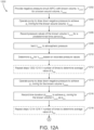
- a process 1200 for generating a model (e.g., f wound ) to relate one or more parameters (e.g., ⁇ leak and ⁇ time ) to a wound volume (e.g., V wound ) is shown, according to some embodiments.
- controller 118 is configured to perform process 1200.
- process 1200 is performed by controller 118 and/or the various components of NPWT system 100.
- process 1200 illustrates various steps that controller 118 can perform to determine f wound .
- process 1200 is the testing procedure described in greater detail above with reference to FIGS. 5-7 .
- Process 1200 includes steps 1202-1226, according to some embodiments.
- Process 1200 includes providing a negative pressure circuit (NPC) with a known volume V system for a known wound volume V wound (step 1202), according to some embodiments.
- NPC negative pressure circuit
- providing the NPC circuit for the known wound includes setting up a NPC circuit by providing wound dressing 112 to patient's skin 116 over wound 114.
- V wound is a known volume of wound 114.
- step 1202 may include configuring NPWT system 100 (e.g., having a known V system ) to perform NPWT for a test wound (e.g., wound 114 with a known volume V wound ).
- step 1202 includes setting up NPWT system 100 and starting therapy device 102.
- Process 1200 includes operating a pump to draw down negative pressure at wound 114 to achieve p 1 at the known wound volume V wound (step 1204), according to some embodiments, in some embodiments, step 1204 is first drawdown period 604.
- the pump is pneumatic pump 120.
- step 1204 includes any of the functionality, techniques, steps, etc., of first drawdown period 604.
- step 1204 is performed by testing procedure controller 148.
- p 1 is 200 mmHg.
- step 1204 is performed by testing procedure controller 148 and pump controller 146.
- Pneumatic pump 120 is configured to produce a negative pressure at wound 114, according to some embodiments.
- step 1204 includes testing procedure controller 148 monitoring pressure measurements at wound 114 via pressure sensors 130, 113, and continuing to cause pneumatic pump 120 to drawdown the negative pressure until the measured/monitored pressure is substantially equal to p 1 .
- step 1204 is also performed by valve controller.
- step 1204 includes valve controller 150 sending a control signal to valve 132 to transition valve 132 into a closed configuration such pneumatic pump 120 can drawdown a negative pressure at wound 114.
- Process 1200 includes recording pressure values of the known volume V wound for a predetermined time period ⁇ t leak (step 1206), according to some embodiments.
- step 1206 is leak rate determination period 606.
- controller 118 is configured to perform step 1206.
- step 1206 is performed by testing procedure controller 148.
- testing procedure controller 148 can be configured to receive pressure measurements from pressure sensors 130/113 over time period ⁇ t leak (e.g., t 2 - t 1 as shown in FIG. 6 ) to perform step 1206.
- step 1206 includes recording multiple pressure values of the negative pressure (e.g., vacuum pressures) of wound 114.
- step 1206 includes recording an initial pressure value (e.g., p 1 ) of wound 114 at a beginning of time period ⁇ t leak , and a final pressure value (e.g., p 2 ) at an end of time period ⁇ t leak .
- step 1206 is performed by testing procedure controller 148 and pressure monitor 152.
- Process 1200 includes venting wound 114 to atmospheric pressure (step 1208), according to some embodiments.
- step 1208 is performed after step 1210.
- step 1208 and step 1210 are performed simultaneously.
- step 1208 is performed by testing procedure controller 148 and valve controller 150.
- step 1208 may include testing procedure controller 148 sending a command to valve controller 150 to transition valve 132 into the open configuration such that wound 114 can return to atmospheric pressure.
- step 1208 is performed by testing procedure controller, valve controller 150, and valve 132.
- step 1208 is vent period 608.
- Process 1200 includes determining the leak rate parameter ⁇ leak for V wound based on the pressure values of wound 114 recorded during step 1206 (step 1210), according to some embodiments.
- step 1210 is performed by testing procedure controller 148.
- ⁇ leak is a difference between an initial pressure value and a final pressure value of time interval ⁇ t leak .
- ⁇ leak is slope 612.
- Process 1200 includes repeating steps 1202-1210 (step 1212), according to some embodiments.
- controller 118 and/or NPWT system 100 repeat steps 1202-1210 X number of times to determine an average value of ⁇ leak to minimize random error.
- step 1212 is optional.
- Process 1200 includes operating the pump (e.g., pneumatic pump 120) to draw down negative pressure at wound 114 to achieve p 1 (step 1214), according to some embodiments.
- step 1214 is second drawdown period 610.
- step 1214 is performed by testing procedure controller 148, pump controller 146, and pneumatic pump 120.
- the pressure is drawn down to pressure p 1 .
- the pressure is drawn down to a pressure greater than or less than pressure p 1 .
- Process 1200 includes recording a time duration ⁇ t drawdown to achieve p 1 for wound 114 as ⁇ time (step 1216), according to some embodiments.
- time duration ⁇ t drawdown is time interval 614.
- ⁇ time is the amount of time that pneumatic pump 120 must operate to achieve pressure p 1 .
- step 1216 is performed by testing procedure controller 148.
- Process 1200 includes repeating steps 1214-1216 Y number of times to determine an average value of ⁇ time (step 1218), according to some embodiments. In some embodiments, steps 1214-1216 are repeated in order to reduce an amount of random error in ⁇ time . In some embodiments, step 1218 is optional.
- Process 1200 includes recording the leak rate parameter ⁇ leak and the drawdown time parameter ⁇ time associated with the value of V wound in a dataset (step 1220), according to some embodiments.
- step 1220 is performed by testing procedure controller 148.
- the matrix N is stored, and additional performances of steps 1202-1220 define additional rows for the matrix N .
- Process 1200 includes repeating steps 1202-1220 for various values of V wound , ⁇ leak , and ⁇ time (step 1222), according to some embodiments.
- each additional iteration of steps 1202-1220 results in an additional row of the matrix N.
- steps 1202-1220 are performed until a sufficient amount of test data is recorded in matrix N .
- steps 1202-1220 are performed for various values of V wound which are typical, and for various leakages ⁇ leak that may be encountered during implementation of NPWT.
- Process 1200 includes generating a model (e.g., f wound ) relating V wound to ⁇ leak and ⁇ time for a current value of V system (step 1224) based on the recorded datasets (e.g., matrix N ), according to some embodiments.
- step 1224 is performed by model generator 154.
- step 1224 includes providing the recorded datasets (e.g., matrix N ) to model generator 154.
- the generated model is matrix A, table 900, f wound , etc.
- step 1224 includes performing any of a regression, a curve fitting technique, a machine learning algorithm, etc., to determine f wound .
- step 1224 includes arranging, sorting, etc., matrix N to generate matrix A or table 900.
- a model is generated for each of multiple values of V system .
- step 1224 includes providing the generated model to wound volume estimator 156.
- Process 1200 includes repeating steps 1202-1224 for various values of V system (step 1226) to determine models that relate ⁇ leak and ⁇ time to V wound for each of the various values of V system , according to some embodiments.
- step 1226 includes performing steps 1204-1224 for various NPWT systems.
- step 1226 is performed by controller 118 and a test technician (e.g., step 1202 may include replacing a current NPWT system with a different system having a different V system ).
- Process 1300 may rely on the model(s) generated in process 1200 by model generator 154. In some embodiments, process 1300 can be performed intermittently throughout NPWT to determine the volume of wound 114. Process 1300 can be performed by controller 118. Process 1300 includes steps 1302-1308, according to some embodiments.
- Process 1400 includes estimating V wound based on the leak rate parameter ⁇ leak and the drawdown time parameter ⁇ time (step 1408), according to some embodiments.
- step 1408 is performed by wound volume estimator 156 using the model generated by model generator 154.
- the model f wound , or table 900, or matrix A (and vectors B and C ) are preloaded into memory 144 of controller 118 for a variety of values of V system .
- step 1408 is step 1306 of process 1300.
- step 1408 includes inputting the leak rate parameter ⁇ leak and the drawdown time parameter ⁇ time into the model (as generated by model generator 154, described in greater detail above) to determine V wound .
- the present disclosure contemplates methods, systems and program products on any machine-readable media for accomplishing various operations.
- the embodiments of the present disclosure can be implemented using existing computer processors, or by a special purpose computer processor for an appropriate system, incorporated for this or another purpose, or by a hardwired system.
- Embodiments within the scope of the present disclosure include program products comprising machine-readable media for carrying or having machine-executable instructions or data structures stored thereon.
- Such machine-readable media can be any available media that can be accessed by a general purpose or special purpose computer or other machine with a processor.
Landscapes
- Health & Medical Sciences (AREA)
- Life Sciences & Earth Sciences (AREA)
- Heart & Thoracic Surgery (AREA)
- Engineering & Computer Science (AREA)
- Veterinary Medicine (AREA)
- Biomedical Technology (AREA)
- Animal Behavior & Ethology (AREA)
- General Health & Medical Sciences (AREA)
- Public Health (AREA)
- Physics & Mathematics (AREA)
- Surgery (AREA)
- Biophysics (AREA)
- Pathology (AREA)
- Molecular Biology (AREA)
- Medical Informatics (AREA)
- Vascular Medicine (AREA)
- Hematology (AREA)
- Anesthesiology (AREA)
- Artificial Intelligence (AREA)
- Signal Processing (AREA)
- Computer Vision & Pattern Recognition (AREA)
- Psychiatry (AREA)
- Physiology (AREA)
- Oral & Maxillofacial Surgery (AREA)
- Dermatology (AREA)
- Business, Economics & Management (AREA)
- Nursing (AREA)
- Critical Care (AREA)
- Emergency Management (AREA)
- Emergency Medicine (AREA)
- Evolutionary Computation (AREA)
- Dentistry (AREA)
- Mathematical Physics (AREA)
- Pulmonology (AREA)
- Fuzzy Systems (AREA)
- Media Introduction/Drainage Providing Device (AREA)
- External Artificial Organs (AREA)
- Measuring And Recording Apparatus For Diagnosis (AREA)
- Measuring Pulse, Heart Rate, Blood Pressure Or Blood Flow (AREA)
Abstract
Description
- The present disclosure relates generally to a wound therapy system, and more particularly to a wound therapy system configured to estimate the volume of a wound.
- Negative pressure wound therapy (NPWT) is a type of wound therapy that involves applying a negative pressure to a wound site to promote wound healing. Some wound treatment systems apply negative pressure to a wound using a pneumatic pump to generate the negative pressure and flow required. Recent advancements in wound healing with NPWT involve applying topical fluids to wounds to work in combination with NPWT. However, it can be difficult to determine the appropriate volume of instillation fluid to deliver to the wound. Additionally, it can be difficult to accurately monitor and track healing progression over time.
- One implementation of the present disclosure is a wound therapy system, according to some embodiments. In some embodiments, the wound therapy system includes a negative pressure circuit, a pump, a pressure sensor, and a controller. In some embodiments, the negative pressure circuit is configured to apply negative pressure to a wound. In some embodiments, the pump is fluidly coupled to the negative pressure circuit and configured to produce a negative pressure at the wound or within the negative pressure circuit. In some embodiments, the pressure sensor is configured to measure the negative pressure within the negative pressure circuit or at the wound. In some embodiments, the controller is configured to perform a testing procedure including a first drawdown period, a leak rate determination period, a vent period, and a second drawdown period. In some embodiments, the controller is configured to receive one or more pressure measurements of the pressure sensor over the leak rate determination period to determine a leak rate parameter. In some embodiments, the controller is configured to monitor an amount of elapsed time over the second drawdown period to determine a drawdown parameter. In some embodiments, the controller is configured to estimate a volume of the wound based on the leak rate parameter and the drawdown parameter.
- In some embodiments, the first drawdown period of the testing procedure includes operating the pump to achieve a predetermined negative pressure within the negative pressure circuit.
- In some embodiments, the leak rate determination period of the testing procedure includes maintaining the predetermined negative pressure for a predetermined time duration and receiving pressure measurements from the pressure sensor during the predetermined time duration.
- In some embodiments, the leak rate parameter is a change in pressure of the negative pressure circuit over the leak rate determination period.
- In some embodiments, the leak rate parameter is a change of pressure with respect to time over at least a portion of the leak rate determination period.
- In some embodiments, the vent period of the testing procedure includes opening a valve of the negative pressure circuit to allow the negative pressure circuit to return to atmospheric pressure.
- In some embodiments, the second drawdown period of the testing procedure includes operating the pump to produce a negative pressure within the negative pressure circuit at a predetermined rate.
- In some embodiments, the drawdown parameter is an amount of time the pump operates at the predetermined rate to achieve a predetermined pressure value within the negative pressure circuit.
- In some embodiments, the controller is further configured to estimate the volume of the wound by inputting the drawdown parameter and the leak rate parameter into a model that relates the volume of the wound to the drawdown parameter and the leak rate parameter.
- In some embodiments, the model is determined by performing the testing procedure for known values of the volume of the wound, and determining the model based on the known values of the volume of the wound, and the leak rate parameters and drawdown parameters associated with each of the known values of the volume of the wound.
- Another implementation of the present disclosure is a method for determining volume of a wound, according to some embodiments. In some embodiments, the method includes providing a negative pressure circuit configured to apply negative pressure to a wound. In some embodiments, the method includes providing a pump fluidly coupled to the negative pressure circuit and configured to produce a negative pressure at the wound or within the negative pressure circuit. In some embodiments, the method includes providing a pressure sensor configured to measure the negative pressure within the negative pressure circuit or at the wound. In some embodiments, the method includes performing a testing procedure for a known value of the volume of the wound. In some embodiments, the testing procedure includes performing a first drawdown over a first drawdown period, performing a leak rate determination over a leak rate determination period, venting the negative pressure circuit, and performing a second drawdown over a second drawdown period. In some embodiments, the method includes receiving one or more pressure measurements of the pressure sensor over the leak rate determination period to determine a leak rate parameter. In some embodiments, the method includes monitoring an amount of elapsed time over the second drawdown period to determine a drawdown parameter. In some embodiments, the method includes generating a model based on the known value of the volume of the wound, the leak rate parameter, and the drawdown parameter. In some embodiments, the model relates the volume of the wound to the leak rate parameter and the drawdown parameter. In some embodiments, the method includes re-performing the steps of performing the testing procedure, receiving the one or more pressure measurements, and monitoring the amount of elapsed time to determine a leak rate parameter and a drawdown parameter for an unknown value of the volume of the wound. In some embodiments, the method further includes estimating the unknown value of the volume of the wound by inputting the leak rate parameter and the drawdown parameter associated with the unknown value of the volume of the wound to the model.
- In some embodiments, the first drawdown includes operating the pump to achieve a predetermined negative pressure within the negative pressure circuit. In some embodiments, the leak rate determination includes maintaining the predetermined negative pressure for a predetermined time duration and receiving pressure measurements from the pressure sensor during the predetermined time duration.
- In some embodiments, the leak rate parameter is a change in pressure of the negative pressure circuit over the leak rate determination period.
- In some embodiments, the leak rate parameter is a rate of change of pressure of the negative pressure circuit with respect to time over at least a portion of the leak rate determination period.
- In some embodiments, venting the negative pressure circuit includes opening a valve of the negative pressure circuit to allow the negative pressure circuit to return to atmospheric pressure.
- In some embodiments, the second drawdown includes operating the pump to produce a negative pressure within the negative pressure circuit at a predetermined drawdown rate.
- In some embodiments, the drawdown parameter is an amount of time the pump operates at the predetermined drawdown rate to achieve a predetermined pressure value within the negative pressure circuit.
- In some embodiments, the model is determined by performing the testing procedure for multiple known values of the volume of the wound to determine multiple values of the leak rate parameter and the drawdown parameter. In some embodiments, the model is determined by performing a regression on the values of the volume of the wound and the values of the leak rate parameter and the drawdown parameter.
- In some embodiments, the model is a lookup table that relates the leak rate parameter and the drawdown parameter to the volume of the wound.
- Another implementation of the present disclosure is a wound therapy device, according to some embodiments. In some embodiments, the wound therapy device includes a pump fluidly coupled to a negative pressure circuit. In some embodiments, the pump is configured to produce a negative pressure at a wound or within the negative pressure circuit. In some embodiments, the negative pressure circuit is configured to apply negative pressure to the wound. In some embodiments, the wound therapy device includes a pressure sensor configured to measure the negative pressure within a negative pressure circuit or at the wound, and a controller. In some embodiments, the controller is configured to operate the pump to produce a negative pressure within the negative pressure circuit, receive one or more pressure measurements of the pressure sensor over a predetermined time period, determine a leakage rate based on the one or more received pressure measurements of the pressure sensor over the predetermined time period, vent the negative pressure circuit to atmospheric pressure, and operate the pump to decrease the pressure within the negative pressure circuit at a predetermined rate. In some embodiments, the controller is configured to monitor an amount of elapsed time that the pump operates at the predetermined rate until a predetermined pressure is achieved within the negative pressure circuit. In some embodiments, the controller is configured to estimate a volume of the wound based on the leakage rate and the amount of elapsed time.
- Those skilled in the art will appreciate that the summary is illustrative only and is not intended to be in any way limiting. Other aspects, inventive features, and advantages of the devices and/or processes described herein, as defined solely by the claims, will become apparent in the detailed description set forth herein and taken in conjunction with the accompanying drawings.
-
-
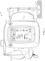
FIG. 1 is a block diagram of a wound therapy system including a therapy device coupled to a wound dressing via tubing, according to an exemplary embodiment. -
FIG. 2 is a block diagram illustrating the therapy device ofFIG. 1 in greater detail when the therapy device operates to draw a vacuum within a negative pressure circuit, according to an exemplary embodiment. -
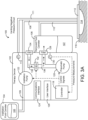
FIG. 3A is a block diagram illustrating the therapy device ofFIG. 1 in greater detail when the therapy device operates to vent the negative pressure circuit, according to an exemplary embodiment. -
FIG. 3B is a block diagram illustrating the therapy device ofFIG. 1 in greater detail when the therapy device uses an orifice to vent the negative pressure circuit, according to an exemplary embodiment. -
FIG. 4 is a block diagram illustrating the therapy device ofFIG. 1 in greater detail when the therapy device operates to deliver instillation fluid to the wound dressing and/or a wound, according to an exemplary embodiment. -
FIG. 5 is a block diagram illustrating a controller of the therapy device ofFIG. 1 in greater detail, according to an exemplary embodiment. -
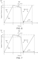
FIGS. 6-7 are graphs illustrating a testing procedure to determine a leak rate parameter and a drawdown time parameter, according to an exemplary embodiment. -
FIG. 8 is a diagram of the wound therapy system ofFIG. 1 , according to an exemplary embodiment. -
FIG. 9 is a table having a top header of various drawdown time parameter values, a side header of various leak rate parameters, and values of wound volume corresponding to various combinations of the drawdown time parameters and the leak rate parameters, according to an exemplary embodiment. -
FIG. 10 is a graph illustrating wound volume and instillation fluid volume over time, according to an exemplary embodiment. -
FIG. 11 is a flowchart of a process for determining an amount of instillation fluid to deliver to a wound based on an estimated wound volume, according to an exemplary embodiment. -
FIGS. 12A-B are a flowchart of a process for generating a model that relates drawdown time parameters and leak rate parameters to wound volume, according to an exemplary embodiment. -
FIG. 13 is a flowchart of a process for determining wound volume and instillation volume, according to an exemplary embodiment. -
FIG. 14 is a flowchart of a process of operating the therapy device ofFIG. 1 , according to an exemplary embodiment. - Referring generally to the FIGURES, a wound therapy system with fluid instillation and removal and components thereof are shown, according to various exemplary embodiments. The wound therapy system may include a therapy device and a wound dressing. The therapy device may include an instillation fluid canister, a removed fluid canister, a valve, a pneumatic pump, an instillation pump, and a controller. The wound dressing can be applied to a patient's skin surrounding a wound. The therapy device can be configured to deliver instillation fluid to the wound and provide negative pressure wound therapy (NPWT) by maintaining the wound at negative pressure. Components of the wound therapy device, the wound dressing, and/or the wound form a negative pressure circuit.
- The controller can estimate the volume of the wound based on the leakage rate of the wound dressing and an amount of time it takes the pneumatic pump to achieve a predetermined negative pressure. The controller can cause the therapy device to perform a testing procedure (e.g., a pressure testing procedure) to determine the leakage rate of the wound dressing and the amount of time it takes the pneumatic pump to achieve the predetermined negative pressure. The leakage rate of the wound dressing and the amount of time it takes the pneumatic pump to achieve the predetermined negative pressure at the wound are the observed parameters. For example, the controller can apply the observed parameters as inputs to a model that defines a relationship between the observed parameters and the volume of the negative pressure circuit and/or the volume of the wound. The model may include a polynomial approximation model, a neural network model, or any other model that relates the observed parameters to the volume of the negative pressure circuit and/or the volume of the wound. In some embodiments, the model is a pre-existing model stored in the controller by the manufacturer of the therapy device. In other embodiments, the controller can generate the model on-site by performing a training procedure.
- The training procedure may be the same as the pressure testing procedure with the exception that the therapy device is connected to a training circuit having a known volume. For example, the wound dressing can be applied to a test device having a known volume rather than to a patient's skin surrounding a wound. The controller can perform the training procedure on various training circuits having various known volumes and may observe the parameters (i.e., the leakage rate and the amount of time to achieve the predetermined negative pressure) of each training circuit. Each of the known volumes may result in different observed parameters. The controller can then associate the known volume of each training circuit with the corresponding parameters. In some embodiments, the controller uses the observed parameters and the known volume of the training circuits to generate the model that defines a relationship between the observed parameters and the volume of the training circuit. The model can then be stored in the therapy device and used to estimate the volume of a wound, as previously described.
- In some embodiments, the controller is configured to execute the pressure testing procedure, observe the parameters, and estimate the wound volume at a plurality of times during wound treatment. The controller can then determine healing progression based on changes in the wound volume during wound treatment. In some embodiments, the controller is configured to determine a volume of instillation fluid to deliver to the wound based on the estimated wound volume. The volume of instillation fluid to deliver may be a predetermined percentage of the volume of the wound (e.g., 20%, 50%, 80%, etc.). The controller can then operate the instillation pump to deliver the determined volume of instillation fluid to the wound. These and other features of the wound therapy system are described in detail below.
- Referring now to
FIGS. 1-4 , a negative pressure wound therapy (NPWT)system 100 is shown, according to an exemplary embodiment.NPWT system 100 is shown to include atherapy device 102 fluidly connected to a wound dressing 112 viatubing skin 116 surrounding awound 114. Several examples ofwound dressings 112 which can be used in combination withNPWT system 100 are described in detail inU.S. Patent No. 7,651,484 granted January 26, 2010 ,U.S. Patent No. 8,394,081 granted March 12, 2013 , andU.S. Patent Application No. 14/087,418 filed November 22, 2013 . The entire disclosure of each of these patents and patent applications is incorporated by reference herein. -
Therapy device 102 can be configured to provide negative pressure wound therapy by reducing the pressure atwound 114.Therapy device 102 can draw a vacuum at wound 114 (relative to atmospheric pressure) by removing wound exudate, air, and other fluids fromwound 114. Wound exudate may include fluid that filters from a patient's circulatory system into lesions or areas of inflammation. For example, wound exudate may include water and dissolved solutes such as blood, plasma proteins, white blood cells, platelets, and red blood cells. Other fluids removed fromwound 114 may includeinstillation fluid 105 previously delivered to wound 114. Instillation fluid 105 can include, for example, a cleansing fluid, a prescribed fluid, a medicated fluid, an antibiotic fluid, or any other type of fluid which can be delivered to wound 114 during wound treatment. Instillation fluid 105 may be held in aninstillation fluid canister 104 and controllably dispensed to wound 114 viainstillation fluid tubing 108. In some embodiments,instillation fluid canister 104 is detachable fromtherapy device 102 to allowcanister 106 to be refilled and replaced as needed. - The
fluids 107 removed fromwound 114 pass through removedfluid tubing 110 and are collected in removedfluid canister 106.Removed fluid canister 106 may be a component oftherapy device 102 configured to collect wound exudate andother fluids 107 removed fromwound 114. In some embodiments, removedfluid canister 106 is detachable fromtherapy device 102 to allowcanister 106 to be emptied and replaced as needed. A lower portion ofcanister 106 may be filled with wound exudate andother fluids 107 removed fromwound 114, whereas an upper portion ofcanister 106 may be filled with air.Therapy device 102 can be configured to draw a vacuum withincanister 106 by pumping air out ofcanister 106. The reduced pressure withincanister 106 can be translated to wound dressing 112 and wound 114 viatubing 110 such that wound dressing 112 and wound 114 are maintained at the same pressure ascanister 106. - Referring particularly to
FIGS. 2-4 , block diagrams illustratingtherapy device 102 in greater detail are shown, according to an exemplary embodiment.Therapy device 102 is shown to include apneumatic pump 120, aninstillation pump 122, avalve 132, afilter 128, and acontroller 118.Pneumatic pump 120 can be fluidly coupled to removed fluid canister 106 (e.g., via conduit 136) and can be configured to draw a vacuum withincanister 106 by pumping air out ofcanister 106. In some embodiments,pneumatic pump 120 is configured to operate in both a forward direction and a reverse direction. For example,pneumatic pump 120 can operate in the forward direction to pump air out ofcanister 106 and decrease the pressure withincanister 106.Pneumatic pump 120 can operate in the reverse direction to pump air intocanister 106 and increase the pressure withincanister 106.Pneumatic pump 120 can be controlled bycontroller 118, described in greater detail below. - Similarly,
instillation pump 122 can be fluidly coupled toinstillation fluid canister 104 viatubing 109 and fluidly coupled to wound dressing 112 viatubing 108.Instillation pump 122 can be operated to deliverinstillation fluid 105 to wound dressing 112 and wound 114 by pumpinginstillation fluid 105 throughtubing 109 andtubing 108, as shown inFIG. 4 .Instillation pump 122 can be controlled bycontroller 118, described in greater detail below. -
Filter 128 can be positioned between removedfluid canister 106 and pneumatic pump 120 (e.g., along conduit 136) such that the air pumped out ofcanister 106 passes throughfilter 128.Filter 128 can be configured to prevent liquid or solid particles from enteringconduit 136 and reachingpneumatic pump 120.Filter 128 may include, for example, a bacterial filter that is hydrophobic and/or lipophilic such that aqueous and/or oily liquids will bead on the surface offilter 128.Pneumatic pump 120 can be configured to provide sufficient airflow throughfilter 128 that the pressure drop acrossfilter 128 is not substantial (e.g., such that the pressure drop will not substantially interfere with the application of negative pressure to wound 114 from therapy device 102). - In some embodiments,
therapy device 102 operates avalve 132 to controllably vent the negative pressure circuit, as shown inFIG. 3A .Valve 132 can be fluidly connected withpneumatic pump 120 and filter 128 viaconduit 136. In some embodiments,valve 132 is configured to control airflow betweenconduit 136 and the environment aroundtherapy device 102. For example,valve 132 can be opened to allow airflow intoconduit 136 viavent 134 andconduit 138, and closed to prevent airflow intoconduit 136 viavent 134 andconduit 138.Valve 132 can be opened and closed bycontroller 118, described in greater detail below. Whenvalve 132 is closed,pneumatic pump 120 can draw a vacuum within a negative pressure circuit by causing airflow throughfilter 128 in a first direction, as shown inFIG. 2 . The negative pressure circuit may include any component ofsystem 100 that can be maintained at a negative pressure when performing negative pressure wound therapy (e.g.,conduit 136, removedfluid canister 106,tubing 110, wound dressing 112, and/or wound 114). For example, the negative pressure circuit may includeconduit 136, removedfluid canister 106,tubing 110, wound dressing 112, and/or wound 114. Whenvalve 132 is open, airflow from the environment aroundtherapy device 102 may enterconduit 136 viavent 134 andconduit 138 and fill the vacuum within the negative pressure circuit. The airflow fromconduit 136 intocanister 106 and other volumes within the negative pressure circuit may pass throughfilter 128 in a second direction, opposite the first direction, as shown inFIG. 3A . - In some embodiments,
therapy device 102 vents the negative pressure circuit via anorifice 158, as shown inFIG. 3B .Orifice 158 may be a small opening inconduit 136 or any other component of the negative pressure circuit (e.g., removedfluid canister 106,tubing 110,tubing 111, wound dressing 112, etc.) and may allow air to leak into the negative pressure circuit at a known rate. In some embodiments,therapy device 102 vents the negative pressure circuit viaorifice 158 rather than operatingvalve 132.Valve 132 can be omitted fromtherapy device 102 for any embodiment in which orifice 158 is included. The rate at which air leaks into the negative pressure circuit viaorifice 158 may be substantially constant or may vary as a function of the negative pressure, depending on the geometry oforifice 158. For embodiments in which the leak rate viaorifice 158 is variable,controller 118 can use a stored relationship between negative pressure and leak rate to calculate the leak rate viaorifice 158 based measurements of the negative pressure. Regardless of whether the leak rate viaorifice 158 is substantially constant or variable, the leakage of air into the negative pressure circuit viaorifice 158 can be used to generate a pressure decay curve for use in estimating volume 160 (seeFIG. 8 ) ofwound 114. - In some embodiments,
therapy device 102 includes a variety of sensors. For example,therapy device 102 is shown to include apressure sensor 130 configured to measure the pressure withincanister 106 and/or the pressure at wound dressing 112 or wound 114. In some embodiments,therapy device 102 includes apressure sensor 113 configured to measure the pressure withintubing 111.Tubing 111 may be connected to wound dressing 112 and may be dedicated to measuring the pressure at wound dressing 112 or wound 114 without having a secondary function such as channelinginstallation fluid 105 or wound exudate. In various embodiments,tubing therapy device 102 to wound dressing 112. Accordingly,tubing 110 may be described as a negative pressure lumen that functions apply negative pressure wound dressing 112 or wound 114, whereastubing 111 may be described as a sensing lumen configured to sense the pressure at wound dressing 112 or wound 114.Pressure sensors therapy device 102, positioned at any location alongtubing pressure sensors 130 and/or 113 can be communicated tocontroller 118.Controller 118 use the pressure measurements as inputs to various pressure testing operations and control operations performed by controller 118 (described in greater detail with reference toFIGS. 5-14 ). -
Controller 118 can be configured to operatepneumatic pump 120,instillation pump 122,valve 132, and/or other controllable components oftherapy device 102. In some embodiments,controller 118 performs a pressure testing procedure by applying a pressure stimulus to the negative pressure circuit. For example,controller 118 may instructvalve 132 to close and operatepneumatic pump 120 to establish negative pressure within the negative pressure circuit. Once the negative pressure has been established,controller 118 may deactivatepneumatic pump 120.Controller 118 may causevalve 132 to open for a predetermined amount of time and then close after the predetermined amount of time has elapsed.Controller 118 may observe a dynamic pressure response of the negative pressure circuit to the pressure stimulus using pressure measurements recorded bypressure sensors 130 and/or 113. The dynamic pressure response may be characterized by a variety of parameters including, for example, a drawdown time parameter αtime and a leak rate parameter αleak. -
Controller 118 can estimatevolume 160 ofwound 114 based on the observed dynamic pressure response. For example,controller 118 can apply the observed parameters as inputs to a model that defines a relationship between the observed parameters and the volume of the negative pressure circuit and/orvolume 160 ofwound 114. The model may include a polynomial approximation model, a neural network model, or any other model that relates the observed parameters to the volume of the negative pressure circuit and/orvolume 160 ofwound 114. In some embodiments, the model is a pre-existing model stored incontroller 118 by the manufacturer oftherapy device 102. In other embodiments,controller 118 can generate the model on-site by performing a training procedure. - The training procedure may be the same as the pressure testing procedure with the exception that
therapy device 102 is connected to a training circuit having a known volume. For example, wound dressing 112 can be applied to a test device having a known volume rather than to a patient'sskin 116 surroundingwound 114.Controller 118 can apply the pressure stimulus to various training circuits having various known volumes and may observe the dynamic pressure response of each training circuit. Each of the known volumes may result in a different dynamic pressure response to the pressure stimulus.Controller 118 can then associate the known volume of each training circuit with the corresponding dynamic pressure response. In some embodiments,controller 118 uses the dynamic pressure responses of the training circuits to generate the model that defines a relationship between the observed parameters of the dynamic pressure response (e.g., depth of purge, rebound, delta, leak rate, etc.) and the volume of the training circuit. The model can then be stored incontroller 118 and used to estimate the volume of awound 114, as previously described. In some embodiments,controller 118 determines one or more sets of values of the drawdown time parameter αtime and the leak rate parameter αleak , where each set of the drawdown time parameter αtime and the leak rate parameter αtime corresponds to a knownvolume 160. In some embodiments,controller 118 uses the one or more sets of values to generate the model. - In some embodiments,
controller 118 is configured to execute the pressure testing procedure, observe the dynamic pressure response, andestimate volume 160 ofwound 114 at a plurality of times during wound treatment.Controller 118 can then determine healing progression based on changes involume 160 ofwound 114 during wound treatment. In some embodiments,controller 118 is configured to determine a volume ofinstillation fluid 105 to deliver to wound 114 based on the estimated value ofvolume 160. The volume ofinstillation fluid 105 to deliver may be a predetermined percentage ofvolume 160 of wound 114 (e.g., 20%, 50%, 80%, etc.).Controller 118 can then operateinstillation pump 122 to deliver the determined volume ofinstillation fluid 105 to wound 114. These and other features ofcontroller 118 are described in greater detail with reference toFIGS. 5-14 . - In some embodiments,
therapy device 102 includes auser interface 126.User interface 126 may include one or more buttons, dials, sliders, keys, or other input devices configured to receive input from a user.User interface 126 may also include one or more display devices (e.g., LEDs, LCD displays, etc.), speakers, tactile feedback devices, or other output devices configured to provide information to a user. In some embodiments, the pressure measurements recorded bypressure sensors 130 and/or 113 are presented to a user viauser interface 126.User interface 126 can also display alerts generated bycontroller 118. For example,controller 118 can generate a "no canister" alert ifcanister 106 is not detected. - In some embodiments,
therapy device 102 includes a data communications interface 124 (e.g., a USB port, a wireless transceiver, etc.) configured to receive and transmit data. Communications interface 124 may include wired or wireless communications interfaces (e.g., jacks, antennas, transmitters, receivers, transceivers, wire terminals, etc.) for conducting data communications external systems or devices. In various embodiments, the communications may be direct (e.g., local wired or wireless communications) or via a communications network (e.g., a WAN, the Internet, a cellular network, etc.). For example,communications interface 124 can include a USB port or an Ethernet card and port for sending and receiving data via an Ethernet-based communications link or network. In another example,communications interface 124 can include a Wi-Fi transceiver for communicating via a wireless communications network or cellular or mobile phone communications transceivers. - Referring now to
FIG. 8 , wound 114 is shown in greater detail, according to some embodiments. In some embodiments, as the pressure withinwound 114 decreases due to operation ofpneumatic pump 120, one or more leaks are formed. For example, air may entervolume 160 ofwound 114 around corners of wound dressing 112. Iftubing volume 160 viaconnectors connectors inner volume 160 of wound 114 (e.g., p 1) is less than atmospheric pressure patm (i.e., the pressure of air outside of wound dressing 112), a pressure differential Δpdiff = patm - p 1 is formed therebetween. In some embodiments, the pressure differential Δpdiff causes air to entervolume 160 and travel throughtubing 110 via any leaks of wound dressing 112 and connectors 162-166. Leaks may form in any other locations between the interface of wound dressing 112 and a patient'sskin 116. In some embodiments, leakages of air intovolume 160 ofwound 114 is correlated to an increased amount of time which is required forpneumatic pump 120 to achieve a negative pressure. - Referring now to
FIG. 5 , a blockdiagram illustrating controller 118 in greater detail is shown, according to an exemplary embodiment.Controller 118 is shown to include aprocessing circuit 140 including aprocessor 142 andmemory 144.Processor 142 may be a general purpose or specific purpose processor, an application specific integrated circuit (ASIC), one or more field programmable gate arrays (FPGAs), a group of processing components, or other suitable processing components.Processor 142 is configured to execute computer code or instructions stored inmemory 144 or received from other computer readable media (e.g., CDROM, network storage, a remote server, etc.). -
Memory 144 may include one or more devices (e.g., memory units, memory devices, storage devices, etc.) for storing data and/or computer code for completing and/or facilitating the various processes described in the present disclosure.Memory 144 may include random access memory (RAM), read-only memory (ROM), hard drive storage, temporary storage, non-volatile memory, flash memory, optical memory, or any other suitable memory for storing software objects and/or computer instructions.Memory 144 may include database components, object code components, script components, or any other type of information structure for supporting the various activities and information structures described in the present disclosure.Memory 144 may be communicably connected toprocessor 142 viaprocessing circuit 140 and may include computer code for executing (e.g., by processor 142) one or more processes described herein. Whenprocessor 142 executes instructions stored inmemory 144,processor 142 generally configures controller 118 (and more particularly processing circuit 140) to complete such activities. -
Controller 118 is shown to include apump controller 146 and avalve controller 150.Pump controller 146 can be configured to operatepumps valve controller 150 can be configured to operatevalve 132 by generating and providing control signals tovalve 132. The control signals provided tovalve 132 can causevalve 132 to open, close, or achieve a specified intermediate position (e.g., one-third open, half open, etc.). In some embodiments,pump controller 146 andvalve controller 150 are used by other components of controller 118 (e.g.,testing procedure controller 148, woundvolume estimator 156, etc.) to operate pumps 120-122 andvalve 132 when carrying out the processes described herein. - In some embodiments,
pump controller 146 uses input from a canister sensor configured to detect whether removedfluid canister 106 is present.Pump controller 146 can be configured to activatepneumatic pump 120 only when removedfluid canister 106 is present. For example,pump controller 146 can check whethercanister 106 is present and can activatepneumatic pump 120 in response to a determination that canister 106 is present. However, ifcanister 106 is not present,pump controller 146 may preventpneumatic pump 120 from activating. Similarly,pump controller 146 can be configured to activateinstillation pump 122 only when instillationfluid canister 104 is present. For example,pump controller 146 can check whethercanister 104 is present and can activateinstillation pump 122 in response to a determination that canister 104 is present. However, ifcanister 104 is not present,pump controller 146 may preventinstillation pump 122 from activating. -
Controller 118 is shown to include apressure monitor 152. Pressure monitor 152 can be configured to monitor the pressure within removedfluid canister 106 and/or the pressure within wound dressing 112 or wound 114 using feedback frompressure sensors 130 and/or 113. For example,pressure sensors 130 and/or 113 may provide pressure measurements to pressure monitor 152. Pressure monitor 152 can use the pressure measurements to determine the pressure withincanister 106 and/or the pressure within wound dressing 112 or wound 114 in real-time. Pressure monitor 152 can provide the pressure value tomodel generator 154,pump controller 146,testing procedure controller 148, and/orvalve controller 150 for use as an input to control processes performed by such components. - Referring now to
FIG. 5 ,controller 118 is shown to include atesting procedure controller 148.Testing procedure controller 148 can be configured to execute a pressure testing procedure to invoke and observe a pressure dynamic response or leakage rate. Iftherapy device 102 is connected to a wound dressing 112 applied to a patient'sskin 116 over awound 114,testing procedure controller 148 can observe the dynamic pressure response and leakage rate of a negative pressure circuit that includesconduit 136, removedfluid canister 106,tubing 110, wound dressing 112, and/or wound 114 (which may have an unknown volume). Iftherapy device 102 is connected to a wound dressing 112 applied to a training device having a known volume,testing procedure controller 148 can observe the dynamic pressure response of a training circuit that includesconduit 136, removedfluid canister 106,tubing 110, wound dressing 112, and/or the training device. - Referring particularly to
FIG. 6 ,graph 600 illustrates a testing procedure that controller 118 (e.g., testing procedure controller 148) may be configured to perform, according to some embodiments. In some embodiments,controller 118 is configured to perform the testing procedure shown ingraph 600 to determine the leak rate parameter αleak and the drawdown time parameter αtime . -
Graph 600 includesseries 602 which shows the relationship between negative pressure (the Y-axis) and time (the X-axis) over the testing procedure, according to some embodiments. In some embodiments, the testing procedure includes afirst drawdown period 604, a leakrate determination period 606, avent period 608, and asecond drawdown period 610. In some embodiments,first drawdown period 604 occurs between time t 0 and time t 1. In some embodiments, leakrate determination period 606 occurs between time t 1 and time t 2. In some embodiments, ventperiod 608 occurs between time t 2 and time t 3. In some embodiments,second drawdown period 610 occurs between time t 3 and time t 4. - During
first drawdown period 604,controller 118 can send a control signal tovalve 132 to transitionvalve 132 into a closed configuration such that air cannot pass throughconduit 138 to vent 134. In some embodiments,testing procedure controller 148 sends a command tovalve controller 150 to transitionvalve 132 into a closed configuration forfirst drawdown period 604. In some embodiments, aftervalve 132 has been transitioned into the closed configuration,testing procedure controller 148 sends control signals to pumpcontroller 146 to draw down (e.g., create a negative pressure) atwound 114. In some embodiments,testing procedures controller 148 sends information to pumpcontroller 146 regarding a drawdown rate (i.e.,
Pump controller 146 is configured to send control signals topneumatic pump 120 to draw down pressure (e.g., create negative pressure) atwound 114 according to the drawdown rate. In some embodiments,pump controller 146 is configured to operatepneumatic pump 120 to drawdown according to one or more predetermined drawdown rates. In some embodiments,testing procedure controller 148 is configured to send a command to pumpcontroller 146 to causepneumatic pump 120 to drawdown at a maximum rate forfirst drawdown period 604. In some embodiments,testing procedure controller 148 sends values of a manipulated variable u to pumpcontroller 146 to causepneumatic pump 120 to drawdown according to a predetermined drawdown rate. For example,testing procedure controller 148 may send pump controller 146 a binary value of manipulated variable u (e.g., u = 1 or u = 0). For example,testing procedure controller 148 may send pump controller 146 a value u 1 = 1 of the manipulated variable to pumpcontroller 146 which indicates thatpump controller 146 should causepneumatic pump 120 to drawdown at a first predetermined drawdown rate. Likewise,testing procedure controller 148 may send pump controller 146 a value u 2 = 1 of the manipulated variable to pumpcontroller 146 which indicates thatpump controller 146 should causepneumatic pump 120 to drawdown at a second predetermined drawdown rate which is greater than the first predetermined drawdown rate.Testing procedure controller 148 may send pump controller 146 a 1xd vector of values of the manipulated variable u such as:
controller 146 should causepneumatic pump 120 to drawdown at a first drawdown rate, u 2 is another binary value of the manipulated variable u indicating whether or not pumpcontroller 146 should causepneumatic pump 120 to drawdown at a second drawdown rate, etc., and ud is a dth binary value of the manipulated variable u indicating whether or not pumpcontroller 146 should causepneumatic pump 120 to drawdown at a dth drawdown rate. For example, if d = 4, and pumpcontroller 146 can causepneumatic pump 120 to drawdown according to four predetermined drawdown rates, vectoru may have the form:
pump controller 146 should causepneumatic pump 120 to drawdown according to the fourth drawdown rate (i.e., u 4 = 1). In some embodiments, the dth drawdown rate (e.g., in this case, the fourth), is the fastest drawdown rate, while the first drawdown rate is the slowest drawdown rate. In some embodiments,testing procedure controller 148 sends pump controller 146 a command to causepneumatic pump 120 to drawdown at the fastest drawdown rate for first drawdown period 604 (e.g., ud = 1).Testing procedure controller 148 can also use the variable drawdown rate of pneumatic pump forsecond drawdown period 610. In some embodiments, the drawdown time parameter αtime is determined acrosssecond drawdown period 610. In some embodiments, if the drawdown rate ofpneumatic pump 120 acrosssecond drawdown period 610 is fast, the volume estimation ofwound 114 is less accurate, but is estimated faster. Likewise, if the drawdown rate ofpneumatic pump 120 acrosssecond drawdown period 610 is slow, the volume estimation ofwound 114 is more accurate, but takes a longer time to estimate. In some embodiments,model generator 154 is configured to determine a model fwound for various predetermined drawdown rates ofsecond drawdown period 610, as described in greater detail below. - In some embodiments,
testing procedure controller 148 uses a setpoint value r as a target value of negative pressure forfirst drawdown period 604. For example, as shown inFIG. 6 , r = p 1 forfirst drawdown period 604. In some embodiments, p 1 is a low pressure (e.g., a high magnitude of negative pressure) value. In some embodiments, p 1 = 200 mmHg. In some embodiments, p 1 is a negative pressure value such that any leaks in wound dressing 112 and/or connectors 162-166 can be monitored. In some embodiments, p 1 is a target value of negative pressure to be achieved atwound 114 at the end offirst drawdown period 604. For example, as shown inFIG. 6 , negative pressure increases throughoutfirst drawdown period 604 until time t 1 where p = p 1. - In some embodiments,
testing procedure controller 148 receives measured pressure values of the pressure p atwound 114 via pressure monitor 152 andpressure sensors 130/113. In some embodiments,testing procedure controller 148 receives values of the pressure p atwound 114 as values of a performance variable y. In some embodiments,testing procedure controller 148 is configured to perform feedback control (e.g., PID control, PI control, etc.) to determine values of the manipulated variable u. In some embodiments,testing procedure controller 148 monitors the values of the performance variable y in real time until the value of the performance variable y is substantially equal to the setpoint value r (e.g., p 1). In some embodiments, once the value of the performance variable y is substantially equal to the value of the setpoint r (e.g.. p = p 1),testing procedure controller 148 sends a value of the manipulated variable u to pumpcontroller 146 to causepneumatic pump 120 to cease the drawdown. For example,testing procedure controller 148 may initially send pump controller 146 a value of the manipulated variable u such as u = 1 until y = r. In some embodiments, once y = r,testing procedure controller 148 sends pump controller 146 a value of the manipulated variable u such as u = 0 so thatpump controller 146 causespneumatic pump 120 to stop drawing down pressure p. In some embodiments, once y = r (or once y is within an acceptable range r ± rx where rx indicates an allowable deviation of y from r),testing procedure controller 148 sends a command to pumpcontroller 146 to cease drawing down negative pressure atwound 114. - After first drawdown period has been completed (at t 1 as shown in graph 600), leak
rate determination period 606 begins, according to some embodiments. Leakrate determination period 606 is used to determineslope 612 which indicates a rate of leakage of the dressing application (e.g., wound dressing 112, connectors 162-166) ofwound 114. In some embodiments,slope 612 is the leak rate parameter αleak. - During leak
rate determination period 606,testing procedure controller 148 causesvalve controller 150 to maintainvalve 132 in the closed configuration for a predetermined period of time Δtleak , according to some embodiments.Testing procedure controller 148 monitors pressure changes over leakrate determination period 606 to determine the leak rate parameter αleak for the specific wound application. As shown ingraph 600, the negative pressure decreases from p 1 to p 2 from time t = t 1 to time t = t 2 . In some embodiments,testing procedure controller 148 monitors change in pressure (e.g., a decrease) over leak rate determination period. For example,testing procedure controller 148 can determine a drop in pressure, p 1 - p 2, over leakrate determination period 606 as the leak rate parameter αleak. In some embodiments, leakrate determination period 606 has a predetermined time duration, Δtleak = t 2 - t 1. In some embodiments,testing procedure controller 148 measures pressure p 1 at time t 1 and pressure p 2 at time t 2 . In some embodiments, the leak rate parameter αleak = p 1 - p 2 over the predetermined time duration Δtleak of leakrate determination period 606. - Leak
rate determination period 606 includestesting procedure controller 148 receiving and storing values of the performance variable y (e.g., negative pressure) over the predetermined time period Δtleak , according to some embodiments. In some embodiments,testing procedure controller 148 receives values of the performance variable y over the predetermined time period Δtleak where Δtleak = t 2 - t 1 . For example,testing procedure controller 148 may receive values of the performance variable y at a sampling rate fsample over Δtleak. In some embodiments, the sampling rate is the number of samples of the performance variable y received frompressure sensors 
testing procedure controller 148 is configured to monitor and record values of the performance variable y frompressure sensors 
rate determination period 606 is fsample · Δtleak = 60 Hz · 10 sec = 600 samples. In some embodiments, the samples are measured bypressure sensors 130/113, andtesting procedure controller 148 records the samples of the performance variable y in a vector, such as:S = [S 1 S 2 ... Sw ] where S 1 is the first recorded value of the performance variable y during leakrate determination period 606, S 2 is the second recorded value of the performance variable y during leakrate determination period 606, etc., Sw is the wth recorded value of the performance variable y during leakrate determination period 606, and w is the number of samples of the performance variable y over leak rate determination period 606 (e.g., w = fsample · (t 2 - t 1)). - In some embodiments,
testing procedure controller 148 also stores a vector of time values associated with the vectorS . For example,testing procedure controller 148 may store a time vectort = [t S1 t S2 ... tSw ] where t S1 is a time at which S 1 is recorded/sampled, t S2 is a time at which S 2 is recorded/sampled, etc., and tSw is a time at which S 1 is recorded/sampled. In some embodiments, t S1 = 0 and tSw = (t 2 - t 1). In some embodiments, t S1 = t 1 and tSw = t 2 . In some embodiments, each of the values of time vector t are spaced apart
1 is considered to be 0,
- In some embodiments,
testing procedure controller 148 is configured to determine slope 612 (i.e., the leak rate parameter αleak ) based on the vectorS of samples of the negative pressure atwound 114, and the time vectort associated withS . In some embodiments,testing procedures controller 148 determines slope 612 (i.e., slope m) between consecutive sampling values (e.g., S 2 and S 1, S 3 and S 2, S 4 and S 3, etc.). For example, iftesting procedure controller 148records 5 sampled values (i.e., w = 5) over leakrate determination period 606 such thatS = [S 1 S 2 S 3 S 4 S 5] andt = [t S1 t S2 t S3 t S4 t S5 ],testing procedure controller 148 determine w - 1 values of slope m. For example,testing procedure controller 148 can determine:

- In some embodiments,
testing procedure controller 148 can determine w - 1 values of m and store the values in a slope vector such as:
-
Testing procedure controller 148 can determine the leak rate parameter αleak based ont ,S , andm . In some embodiments,testing procedure controller 148 determines an average of the values ofm as αleak. For example,testing procedure controller 148 can determine:
Testing procedure controller 148 also determines a standard deviation associated with the leak rate parameter αleak :

- In some embodiments,
testing procedure controller 148 selects the maximum or minimum value ofm as αleak. For example,testing procedure controller 148 may determine αleak as:

- In some embodiments,
testing procedure controller 148 uses the initial and final values oft andS to determine an overall slope m over the entirety of leakrate determination period 606 as the leak rate parameter αleak.Testing procedure controller 148 determines:
- In some embodiments, Δtleak (e.g., time between t 2 and t 1) of leak
rate determination period 606 is a predetermined time period. For example Δtleak may be 10 seconds, 30 seconds, 5 minutes, etc., according to some embodiments. If Δtleak is a predetermined time period,testing procedure controller 148 can determine the leak rate parameter αleak as the change in pressure (e.g., p 2 - p 1) over the predetermined time period. For example, αleak = p 2 - p 1 assuming Δtleak is a predetermined value. Leakrate determination period 606 is used to determine αleak which characterizes a seal quality atwound 114 and quantifies a leak rate atwound 114. In some embodiments, αleak characterizes an ability ofwound 114 to hold a negative pressure. For example, if αleak is very low, this indicates thatwound 114 is well sealed and can hold a negative pressure well (e.g., without any leaks) since the pressure drop across leak rate determination period is negligible orslope 612 is a near-zero value. Similarly, if αleak is very high, this indicates thatwound 114 is not well sealed and may not hold a negative pressure as well (e.g., identified by a large pressure drop across leakrate determination period 606 or anegative slope 612 with a large magnitude), according to some embodiments. - In some embodiments, after leak
rate determination period 606 is completed,testing procedure controller 148 stores the values of αleak ,m ,t , andS collected/determined over leakrate determination period 606 and proceeds to ventperiod 608. Duringvent period 608,testing procedure controller 148 sends a command tovalve controller 150 to transitionvalve 132 into the open configuration to allowwound 114 to return to atmospheric pressure, according to some embodiments. In some embodiments,testing procedure controller 148 causesvalve controller 150 to maintainvalve 132 in the open configuration for a predetermined amount of time such that the pressure p withinwound 114 can return to atmospheric pressure (e.g., 0 mmHg negative pressure). In some embodiments,testing procedure controller 148 monitors the real time value of the performance variable y received frompressure sensors 130/113 via pressure monitor 152 and causesvalve controller 150 to maintainvalve 132 in the open configuration until the received pressure measurements frompressure sensors 130/113 are substantially equal to atmospheric pressure, as shown at t 3. - After
wound 114 has returned to atmospheric pressure,testing procedure controller 148 proceeds tosecond drawdown period 610, according to some embodiments. In some embodiments,second drawdown period 610 is performed to determine the drawdown time parameter αtime. The drawdown time parameter αtime is an amount of time required to achieve a desired negative pressure value (e.g., p 1). In some embodiments, the drawdown time parameter αtime istime interval 614.Time interval 614 as shown in FIG. 17 is greater thantime interval 614 as shown in FIG. 16, according to some embodiments. In some embodiments, the value oftime interval 614 can increase due to a larger volume ofwound 114 and/or a higher leak rate (e.g., a higher value of αleak ).Slope 612 as shown inFIG. 7 is substantially equal toslope 612 as shown inFIG. 6 , according to some embodiments. This may indicate that the wound application (e.g., dressing 112) of the testing procedure as shown inFIG. 6 has a substantially equal leak rate compared to the wound application (e.g., dressing 112) of the testing procedure as shown inFIG. 7 . Therefore, the increased value oftime interval 614 as shown inFIG. 7 , compared to the value oftime interval 614 as shown inFIG. 6 , may be due to the testing procedure ofgraph 700 being performed on awound 114 with a larger volume thanwound 114 of the testing procedure ofgraph 600. -
Testing procedure controller 148 can determine the drawdown time parameter αtime by sending a command (e.g., a value of the manipulated variable u) to pumpcontroller 146 to causepneumatic pump 120 to drawdown at a rate of
Testing procedure controller 148 can receive the pressure measurements from pressure monitor 152 and/orpressure sensors 130/113 and determine an amount of time thatpneumatic pump 120 operates to achieve a desired pressure (e.g., p 1) as αtime. In some embodiments,testing procedure controller 148 can send a command to pumpcontroller 146 to causepneumatic pump 120 to drawdown according to various drawdown rates
- In some embodiments,
testing procedure controller 148 is configured to send a command tovalve controller 150 to transitionvalve 132 into the closed configuration to initiatesecond drawdown period 610. In some embodiments, aftervalve 132 has been transitioned into the closed configuration,testing procedure controller 148 sends a command to pumpcontroller 146 to initiate a second drawdown. In some embodiments,testing procedure controller 148 sends a value of the manipulated variable u to pumpcontroller 146 to causepneumatic pump 120 to drawdown the negative pressure atwound 114. In some embodiments,testing procedure controller 148 sends a command (e.g., a value of the manipulated variable u) to pumpcontroller 146 to causepneumatic pump 120 to drawdown according to a predetermined drawdown operation. In some embodiments, the predetermined drawdown operation includes increasing the voltage supplied topneumatic pump 120 ifpneumatic pump 120 cannot achieve the desired negative pressure (e.g., p 1) given the current voltage. In some embodiments, the voltage increases ofpneumatic pump 120 are performed at predetermined/known time intervals. - Similar to
first drawdown period 604,testing procedure controller 148 can send values of the manipulated variable u to pumpcontroller 146 to causepneumatic pump 120 to drawdown at a variety of drawdown rates forsecond drawdown period 610. In some embodiments, faster drawdown rates result in a less accurate estimation of the drawdown time parameter αtime but can advantageously be used to estimate the drawdown time parameter αtime faster. Likewise, slower drawdown rates advantageously result in a more accurate estimation of the drawdown time parameter αtime but require a longer amount of time to estimate the drawdown time parameter αtime , according to some embodiments. - During
second drawdown period 610,testing procedure controller 148 monitors the value of the performance variable y received frompressure sensors wound 114 thatpneumatic pump 120 is trying to achieve (e.g., a target pressure value). For example, the setpoint value r may be p 1. In some embodiments, the setpoint value r is greater than or less than p 1. In this way, the target pressure value ofsecond drawdown period 610 may be the same, or greater than, or less than the target pressure value offirst drawdown period 604. -
Testing procedure controller 148 continues monitoring the value of the performance variable y and monitoring an amount of elapsed time since the beginning (e.g., t 3) ofsecond drawdown period 610, according to some embodiments. In some embodiments,testing procedure controller 148 includes a timer configured to reset at the beginning of second drawdown period 610 (e.g., at t 3) or to store a time at whichsecond drawdown period 610 begins (e.g., store the value of t 3). In some embodiments, the timer resets or records the time value immediately aftervalve 132 has transitioned into the closed configuration and oncepneumatic pump 120 has begun drawing down pressure atwound 114. - In some embodiments, once the value of the performance variable y is substantially equal to the setpoint r (e.g., equal to, within a negligible amount, etc.), the timer of
testing procedure controller 148 records time t 4. In some embodiments,testing procedure controller 148 monitors the amount of time (i.e., t 4 - t 3) required to achieve the desired negative pressure value (e.g., r, p 1). In some embodiments,testing procedure controller 148 monitors the elapsed time to drawdown to p 1 or r. In some embodiments, the amount of elapsed time Δtdrawdown = t 4 - t 3. In some embodiments, the amount of elapsed time Δtdrawdown is the drawdown time parameter αtime . -
Testing procedure controller 148 can perform the testing procedure as described in greater detail above to determine values of the leak rate parameter αleak and the drawdown time parameter αtime for a known volume ofwound 114 and/or a known training circuit volume. For example,testing procedure controller 148 can perform the testing procedure multiple times for a variety of several training circuits having known volumes (e.g., 50 cc, 100 cc, 200 cc, 300 cc, etc.). In some embodiments,testing procedure controller 148 is configured to perform the testing procedure several times for each of the training circuits having known volumes. In some embodiments, the resulting values of the leak rate parameter αleak and the drawdown time parameter αtime are averaged for each of the training circuits to mitigate an amount of random error. For example, the testing procedure may be performed 10 times for a training circuit having the known volume of 50 cc and the leak rate parameter αleak and the drawdown time parameter αtime can be averaged to reduce random error. In some embodiments, the testing procedure is performed for various NPWT systems having differentpneumatic pumps 120, therapy pressures, training circuit volumes, etc. In some embodiments,model generator 154 is configured to generate a model for each of multiple training circuits using any of the methods and techniques described in greater detail below. - In some embodiments, the training circuit volume includes known volume values of the various pipes, canisters, tubes, etc., which
pneumatic pump 120 is configured to draw down. In some embodiments, the training circuit volume includes a known volume ofwound 114, Vwound. In some embodiments, the training circuit volume is:
pneumatic pump 120 is configured to produce a negative pressure within (e.g.,conduit 136, removedfluid canister 106,tubing 110, wound dressing 112, and/or wound 114), and Vwound is a known volume ofwound 114. - In some embodiments, the testing procedure can be performed multiple times for a variety of values of Vwound . For example, the testing procedure can be performed by
controller 118 for a value of Vwound = 50cc, Vwound = 100 cc, Vwound = 125 cc, etc. In some embodiments, the testing procedure is performed multiple times for each value of Vwound to determine average parameter values associated with the particular value of Vwound. In some embodiments, Vsystem is held constant while the testing procedure is repeated for various values of Vwound. In this way, changes in the overall volume of the training circuit, Vtraining are due to changes in Vwound. The testing procedure can also be performed multiple times for each value of Vwound having multiple leak rates. In some embodiments,testing procedure controller 148 is configured to providemodel generator 154 with the leak rate parameter αleak and the drawdown time parameter αtime for each combination of leak rate and Vwound resulting from performing the testing procedure. - In some embodiments,
controller 118 performs the testing procedure for various systems having different values of Vsystem. In some embodiments,controller 118 performs the testing procedure multiple times for various values of Vwound for each of the various systems. In some embodiments,model generator 154 is configured to generate a model for each of the various systems using any of the methods and techniques described in greater detail below. For example,model generator 154 can generate a model for various training circuits which may be used during NPWT. - In some embodiments,
model generator 154 is configured to determine a model to relate the recorded/determined parameters (i.e., αleak and αtime ) to Vwound for the known values of Vwound . This model can then be used during NPWT to determine the volume of anunknown wound 114.Model generator 154 can be configured to perform a multi-variable regression (e.g., perform a multi-variable polynomial curve fit, perform a multi-variable linear regression), use a neural network, or create a matrix/table to create a model that relates the parameters to known values of Vwound. In some embodiments,model generator 154 creates a model for a variety of values of Vsystem. For example,model generator 154 can create a table for each of a variety of typical values of Vsystem which correspond to various NPWT circuits that may be used during NPWT. - Referring again to
FIG. 5 ,controller 118 is shown to include amodel generator 154, according to some embodiments.Model generator 154 can be configured to generate a model that defines a relationship between the parameters of the dynamic pressure response and the volume ofwound 114. To generate the model,model generator 154 can causetesting procedure controller 148 to run the pressure testing procedure outlined above for several different training circuits having several different known volumes (e.g., 50 cc, 100 cc, 200 cc, 300 cc, etc.). When the pressure testing procedure is performed on a training circuit having a known volume, the pressure testing procedure may be referred to as a training procedure. Each performance of the training procedure may include applying the pressure stimulus to a training circuit having a known volume, observing the dynamic pressure response of the training circuit to the pressure stimulus (e.g., determining/measuring αleak and αtime ), and associating the known volume with the dynamic pressure response of the training circuit. - In some embodiments,
model generator 154 records the values of the parameters of the dynamic pressure response (i.e., the leak rate parameter αleak and the drawdown time parameter αtime ) for each known volume and associates those values with the known volume. The values of the parameters and the known volume form a set of training data which can be used to construct the model. The values of the parameters form a set of model input training data, whereas the known volumes form a set of model output training data.Model generator 154 can use any of a variety of model generation techniques to construct a model (i.e., a mathematical model) that relates the values of the parameters to the corresponding volume in the set of training data. - In some embodiments,
model generator 154 creates a n by m matrix A (i.e., a model) for each typical value of Vsystem (i.e., typical negative pressure wound therapy systems). In some embodiments, the matrix A relates the leak rate parameter values αleak and the drawdown time parameter values αdrawdown to the known wound volume values Vwound associated with the parameters. In some embodiments, the matrix A has the form:
wound 114 corresponding to a different value of the drawdown time parameter αtime , each row represents different volumes ofwound 114 corresponding to a different leak rate parameter αleak, and each element of the matrix represents a volume of Vwound which corresponds to the particular combination of αtime and αleak. In some embodiments,model generator 154 is configured to receive various data sets where each data set includes a value of Vwound for which the particular test was performed, and the values of αtime and αleak that resulted from the test. In some embodiments,model generator 154 is configured to receive data sets from each iteration of the test and create matrix A based on the data sets. In some embodiments, matrix A is created (e.g., sorted, arranged, generated, constructed, etc.) such that the values of αtime (e.g., associated with the columns of matrix A) increase from left to right, and such that the values of αleak (e.g., associated with the rows of matrix A) increase from top to bottom of matrix A. - In some embodiments,
model generator 154 also generates vectors which correspond to the rows and columns of matrix A. In some embodiments, the vectors are row and column vectors of the drawdown time parameters αtime and the leak rate parameters αleak which were determined through testing for the associated volume values. For example, the vector of the drawdown time parameters αtime may be referred to as vector C and have the form:

- In some embodiments,
model generator 154 creates a table 900 as shown inFIG. 9 based on the datasets received fromtesting procedure controller 148. Table 900 includes a horizontal/top header 902 and a vertical/side header 904, according to some embodiments. In some embodiments,top header 902 represents various values of αtime , and columns corresponding to various values of Vwound. Side header 904 represents various values of αleak and rows correspond to various values of Vwound. In some embodiments,top header 902 and the corresponding columns of Vwound values are sorted in an ascending order of αtime , with lower values of αtime farther left and higher values of αtime farther right. Likewise,side header 904 is sorted in ascending order of αleak with lower values of αleak at the top ofside header 904 and higher values of αleak at the bottom ofside header 904, according to some embodiments. - In some embodiments,
model generator 154 performs a multi-variable regression based on the values of Vwound and the corresponding αtime and αleak parameters. In some embodiments,model generator 154 performs a multi-variable linear regression to determine the equation:
model generator 154 by performing the multi-variable linear regression. - In some embodiments,
model generator 154 performs a multi-variable non-linear regression to determine the equation:

- In some embodiments,
model generator 154 creates fwound using a polynomial approximation model to relate the values of the parameters to the corresponding volume. To generate a polynomial approximation model,model generator 154 can perform a curve fitting process such as polynomial regression using any of a variety of regression techniques. Examples of regression techniques which can be used bymodel generator 154 include least squares, ordinary least squares, linear least squares, partial least squares, total least squares, generalized least squares, weighted least squares non-linear least squares, non-negative least squares, iteratively reweighted least squares, ridge regression, least absolute deviations, Bayesian linear regression, Bayesian multivariate linear regression, etc. - In some embodiments, fwound is generated by
model generator 154 using a neural network. To generate a neural network model,model generator 154 can perform a machine learning process. Examples of machine learning techniques which can be used bymodel generator 154 include decision tree learning, association rule learning, artificial neural networks, deep learning, inductive logic programming, support vector machines, clustering, Bayesian networks, reinforcement learning, representation learning, similarity and metric learning, sparse dictionary learning, genetic algorithms, rule-based machine learning, etc. - Referring still to
FIG. 5 ,controller 118 is shown to include woundvolume estimator 156, according to some embodiments. In some embodiments, woundvolume estimator 156 is provided with any of matrix A and the associated vectors B and C, table 900, and/or the mathematical model determined by model generator 154 (e.g., fwound ). In some embodiments, woundvolume estimator 156 is configured to causetesting procedure controller 148 to perform the testing procedure as described in greater detail above with reference toFIG. 6 for an unknown wound volume. In some embodiments, woundvolume estimator 156 is configured to perform the testing procedure. For example, woundvolume estimator 156 may be configured to perform any of the functionality of testing procedure controller 148 (e.g., to performfirst drawdown period 604, operatevalve 132, controlpneumatic pump 120, etc.). In some embodiments, woundvolume estimator 156 determines the values of αtime and αleak or receives the determined values of αtime and αleak fromtesting procedure controller 148. In some embodiments, woundvolume estimator 156 uses any of the mathematical models (e.g., fwound ), matrix A, table 900, etc., generated and received frommodel generator 154 to determine an estimated value of the unknown value of Vwound. In some embodiments, ifwound volume estimator 156 uses table 900 and/or matrix A, and one or both of the values of αtime and αleak do not correspond to the values of αtime and αleak as stored in vectors B and C or in table 900, woundvolume estimator 156 is configured to perform an interpolation to determine Vwound . - In some embodiments, wound
volume estimator 156 uses table 900 to determine the unknown value Vwound based on the determined parameters αtime and αleak resulting from performing the testing procedure onwound 114 with an unknown volume. In some embodiments, woundvolume estimator 156 first checks through the values ofside header 904 to determine if any of the values of αleak inside header 904 are substantially equal to the value of αleak determined from performing the testing procedure onwound 114 with the unknown value of Vwound. For example, ifwound volume estimator 156 determines that αleak is substantially equal to α leak,2 ofside header 904, woundvolume estimator 156 determines that the value of Vwound is one of the values of V in the row corresponding to α leak,2. Next, woundvolume estimator 156 can compare the various values of αtime in thetop header 902 to the value of αtime determined from performing the testing procedure onwound 114. For example, ifwound volume estimator 156 determines that αtime is substantially equal to α time,5, and αleak is substantially equal to α leak,2 , woundvolume estimator 156 can determine that the volume ofwound 114 is substantially equal to V 2,5. - In some embodiments, if
wound volume estimator 156 determines that αleak and/or αtime do not correspond to values ofside header 904 andtop header 902, respectively, woundvolume estimator 156 can perform an interpolation or an extrapolation to determine the volume ofwound 114. In some embodiments, woundvolume estimator 156 uses any of the values of table 900 in a multi-variable linear interpolation (or extrapolation) to determine the volume ofwound 114. In some embodiments, woundvolume estimator 156 performs a non-linear interpolation to determine the volume ofwound 114. -
Wound volume estimator 156 can be similarly configured to determine the volume ofwound 114 using matrix A and vectors B and C. For example, woundvolume estimator 156 can compare the value of αtime to values of the elements of vector C to determine a column value of matrix A, and compare the value of αleak to values of the elements of vector B to determine a row value of matrix A. For example, if αtime is equal to the fifth element of vector C and αleak is equal to the tenth element of vector C, woundvolume estimator 156 can select A(10,5) or V 10,5 as Vwound forwound 114. Likewise, woundvolume estimator 156 can be configured to interpolate or extrapolate values of matrix A to determine values of Vwound that are associated with a value of αtime and/or αleak not included in vector B and vector C. In some embodiments, woundvolume estimator 156 is configured to use a linear multi-variable interpolation technique or a non-linear interpolation technique. - In some embodiments, wound
volume estimator 156 is configured to use any of the linear regression equations (e.g., Vwound = C 1 αtime + C 2 αleak + C 3), the non-linear regression equation (e.g., Vwound = f 1(αtime ) + f 2(αleak )), or any of the mathematical models (e.g., generally referred to as Vwound = fwound (αtime, αleak )) determined using any of the methods described in greater detail above (e.g., generated using a machine learning algorithm, using a polynomial curve-fit, using a linear regression, etc.) using the data received fromtesting procedure controller 148 for the known volumes. For example, woundvolume estimator 156 can input the determined values of αleak and αtime (e.g., the parameters resulting from performing the testing procedure on awound 114 with an unknown volume) into fwound to determine the volume Vwound ofwound 114. In some embodiments, woundvolume estimator 156 is configured to select an appropriate model (e.g., an appropriate table 900, an appropriate matrix A, an appropriate fwound ) based on a volume (e.g., Vsystem ) of circuit whichpneumatic pump 120 is configured to drawdown. For example, woundvolume estimator 156 can select an appropriate fwound model generated from a testing procedure for a system having a similar volume from a database of various fwound models. - Advantageously, using both αtime and αleak to determine Vwound reduces inaccuracies or deviations in αtime due to air leaking into
inner volume 160 ofwound 114, according to some embodiments. For example, a wound application for a wound having volume Vwound with a high leak rate (e.g., a high value of αleak ) may have a higher value of αtime when compared to a wound with the same volume Vwound but a lower leak rate (e.g., a lower value of αleak ). By taking both αtime and αleak into account,model generator 154 and woundvolume estimator 156 can account for the degree of leakage for the particular wound and accurately determine Vwound , regardless of high or low leakage rates (e.g., high or low values of αleak ). - Referring now to
FIGS. 10-11 , agraph 1000 andprocess 1100 illustrating an application of the wound volume estimates are shown, according to an exemplary embodiment.Controller 118 can use the estimated wound volume to calculate a volume ofinstillation fluid 105 to deliver to wound 114 (step 1102). In some embodiments,controller 118 calculates the volume ofinstillation fluid 105 to deliver to wound 114 by multiplying the estimated wound volume by a fluid instillation factor. The fluid instillation factor may be less than one (i.e., between zero and one) such that the calculated volume ofinstillation fluid 105 is less than the volume ofwound 114. In some embodiments, the fluid instillation factor is between approximately 0.2 and approximately 0.8. However, it is contemplated that the fluid instillation factor can have any value in various alternative embodiments. - In
graph 1000,line 1002 represents the estimated volume ofwound 114 as a function of time, whereasline 1004 represents the calculated volume ofinstillation fluid 105 to deliver to wound 114 over time. At time t 1, the estimated volume ofwound 114 is V 4. The estimated wound volume V 4 at time t 1 can be multiplied by the fluid instillation factor F (e.g., F = 0.8) to calculate the volume of instillation fluid 105 V 3 to deliver to wound 114 at time t 1 (i.e., V 4 * F = V 3). Aswound 114 heals, the estimated volume ofwound 114 decreases and reaches a value of V 2 at time t 2 . The estimated wound volume V 2 at time t 2 can be multiplied by the fluid instillation factor F to calculate the volume of instillation fluid 105 V 1 to deliver to wound 114 at time t 2 (i.e., V 2 * F = V 1). -
Controller 118 can then operate a pump to deliver the calculated volume ofinstillation fluid 105 to wound 114 (step 1104).Step 1104 can includeoperating instillation pump 122 to drawinstillation fluid 105 frominstillation fluid canister 104 and deliverinstillation fluid 105 to wound 114 viatubing instillation fluid 105 is also used to control the operation ofpneumatic pump 120. For example,controller 118 can operatepneumatic pump 120 to remove the volume ofinstillation fluid 105 fromwound 114 viatubing 110. The amount of time thatpneumatic pump 120 operates may be a function of the volume ofinstillation fluid 105 that was delivered to wound 114. - Referring now to
FIGS. 12A-B , aprocess 1200 for generating a model (e.g., fwound ) to relate one or more parameters (e.g., αleak and αtime ) to a wound volume (e.g., Vwound ) is shown, according to some embodiments. In some embodiments,controller 118 is configured to performprocess 1200. In some embodiments,process 1200 is performed bycontroller 118 and/or the various components ofNPWT system 100. In some embodiments,process 1200 illustrates various steps thatcontroller 118 can perform to determine fwound. In some embodiments,process 1200 is the testing procedure described in greater detail above with reference toFIGS. 5-7 .Process 1200 includes steps 1202-1226, according to some embodiments. -
Process 1200 includes providing a negative pressure circuit (NPC) with a known volume Vsystem for a known wound volume Vwound (step 1202), according to some embodiments. In some embodiments, providing the NPC circuit for the known wound includes setting up a NPC circuit by providing wound dressing 112 to patient'sskin 116 overwound 114. In some embodiments, Vwound is a known volume ofwound 114. For example,step 1202 may include configuring NPWT system 100 (e.g., having a known Vsystem ) to perform NPWT for a test wound (e.g., wound 114 with a known volume Vwound ). In some embodiments,step 1202 includes setting upNPWT system 100 and startingtherapy device 102. -
Process 1200 includes operating a pump to draw down negative pressure atwound 114 to achieve p 1 at the known wound volume Vwound (step 1204), according to some embodiments, in some embodiments,step 1204 isfirst drawdown period 604. In some embodiments, the pump ispneumatic pump 120. In some embodiments,step 1204 includes any of the functionality, techniques, steps, etc., offirst drawdown period 604. In some embodiments,step 1204 is performed bytesting procedure controller 148. In some embodiments, p 1 is 200 mmHg. In some embodiments,step 1204 is performed bytesting procedure controller 148 andpump controller 146.Pneumatic pump 120 is configured to produce a negative pressure atwound 114, according to some embodiments. In some embodiments,step 1204 includestesting procedure controller 148 monitoring pressure measurements atwound 114 viapressure sensors pneumatic pump 120 to drawdown the negative pressure until the measured/monitored pressure is substantially equal to p 1. In some embodiments,step 1204 is also performed by valve controller. In some embodiments,step 1204 includesvalve controller 150 sending a control signal tovalve 132 to transitionvalve 132 into a closed configuration suchpneumatic pump 120 can drawdown a negative pressure atwound 114. -
Process 1200 includes recording pressure values of the known volume Vwound for a predetermined time period Δtleak (step 1206), according to some embodiments. In some embodiments,step 1206 is leakrate determination period 606. In some embodiments,controller 118 is configured to performstep 1206. In some embodiments,step 1206 is performed bytesting procedure controller 148. For example,testing procedure controller 148 can be configured to receive pressure measurements frompressure sensors 130/113 over time period Δtleak (e.g., t 2 - t 1 as shown inFIG. 6 ) to performstep 1206. In some embodiments,step 1206 includes recording multiple pressure values of the negative pressure (e.g., vacuum pressures) ofwound 114. In some embodiments,step 1206 includes recording an initial pressure value (e.g., p 1) ofwound 114 at a beginning of time period Δtleak , and a final pressure value (e.g., p 2) at an end of time period Δtleak. In some embodiments,step 1206 is performed bytesting procedure controller 148 and pressure monitor 152. -
Process 1200 includes ventingwound 114 to atmospheric pressure (step 1208), according to some embodiments. In some embodiments,step 1208 is performed afterstep 1210. In some embodiments,step 1208 andstep 1210 are performed simultaneously. In some embodiments,step 1208 is performed bytesting procedure controller 148 andvalve controller 150. For example,step 1208 may includetesting procedure controller 148 sending a command tovalve controller 150 to transitionvalve 132 into the open configuration such that wound 114 can return to atmospheric pressure. In some embodiments,step 1208 is performed by testing procedure controller,valve controller 150, andvalve 132. In some embodiments,step 1208 isvent period 608. -
Process 1200 includes determining the leak rate parameter αleak for Vwound based on the pressure values ofwound 114 recorded during step 1206 (step 1210), according to some embodiments. In some embodiments,step 1210 is performed bytesting procedure controller 148. In some embodiments, αleak is a difference between an initial pressure value and a final pressure value of time interval Δtleak. In some embodiments, αleak isslope 612. In some embodiments,
-
Process 1200 includes repeating steps 1202-1210 (step 1212), according to some embodiments. In some embodiments,controller 118 and/orNPWT system 100 repeat steps 1202-1210 X number of times to determine an average value of αleak to minimize random error. In some embodiments,step 1212 is optional. -
Process 1200 includes operating the pump (e.g., pneumatic pump 120) to draw down negative pressure atwound 114 to achieve p 1 (step 1214), according to some embodiments. In some embodiments,step 1214 issecond drawdown period 610. In some embodiments,step 1214 is performed bytesting procedure controller 148,pump controller 146, andpneumatic pump 120. In some embodiments, the pressure is drawn down to pressure p 1. In some embodiments, the pressure is drawn down to a pressure greater than or less than pressure p 1. -
Process 1200 includes recording a time duration Δtdrawdown to achieve p 1 forwound 114 as αtime (step 1216), according to some embodiments. In some embodiments, time duration Δtdrawdown istime interval 614. In some embodiments, αtime is the amount of time thatpneumatic pump 120 must operate to achieve pressure p 1. In some embodiments,step 1216 is performed bytesting procedure controller 148. -
Process 1200 includes repeating steps 1214-1216 Y number of times to determine an average value of αtime (step 1218), according to some embodiments. In some embodiments, steps 1214-1216 are repeated in order to reduce an amount of random error in αtime. In some embodiments,step 1218 is optional. -
Process 1200 includes recording the leak rate parameter αleak and the drawdown time parameter αtime associated with the value of Vwound in a dataset (step 1220), according to some embodiments. In some embodiments,step 1220 is performed bytesting procedure controller 148. In some embodiments,step 1220 includes generating a matrix N = [αtime αleak Vwound ] and providing matrix N tomodel generator 154. In some embodiments, the matrix N is stored, and additional performances of steps 1202-1220 define additional rows for the matrix N. -
Process 1200 includes repeating steps 1202-1220 for various values of Vwound , αleak , and αtime (step 1222), according to some embodiments. In some embodiments, each additional iteration of steps 1202-1220 results in an additional row of the matrix N. In some embodiments, steps 1202-1220 are performed until a sufficient amount of test data is recorded in matrix N. In some embodiments, steps 1202-1220 are performed for various values of Vwound which are typical, and for various leakages αleak that may be encountered during implementation of NPWT. -
Process 1200 includes generating a model (e.g., fwound ) relating Vwound to αleak and αtime for a current value of Vsystem (step 1224) based on the recorded datasets (e.g., matrix N), according to some embodiments. In some embodiments,step 1224 is performed bymodel generator 154. In some embodiments,step 1224 includes providing the recorded datasets (e.g., matrix N) tomodel generator 154. In some embodiments, the generated model is matrix A, table 900, fwound, etc. In some embodiments,step 1224 includes performing any of a regression, a curve fitting technique, a machine learning algorithm, etc., to determine fwound. In some embodiments,step 1224 includes arranging, sorting, etc., matrix N to generate matrix A or table 900. In some embodiments, a model is generated for each of multiple values of Vsystem. In some embodiments,step 1224 includes providing the generated model to woundvolume estimator 156. -
Process 1200 includes repeating steps 1202-1224 for various values of Vsystem (step 1226) to determine models that relate αleak and αtime to Vwound for each of the various values of Vsystem , according to some embodiments. In some embodiments,step 1226 includes performing steps 1204-1224 for various NPWT systems. In some embodiments,step 1226 is performed bycontroller 118 and a test technician (e.g.,step 1202 may include replacing a current NPWT system with a different system having a different Vsystem ). - Referring now to
FIG. 13 , aprocess 1300 for determining the volume Vwound of wound 114 (i.e., if the volume ofwound 114 is unknown) is shown, according to some embodiments.Process 1300 may rely on the model(s) generated inprocess 1200 bymodel generator 154. In some embodiments,process 1300 can be performed intermittently throughout NPWT to determine the volume ofwound 114.Process 1300 can be performed bycontroller 118.Process 1300 includes steps 1302-1308, according to some embodiments. -
Process 1300 includes performing steps 1202-1210 ofprocess 1200 to determine the leak rate parameter αleak for an unknown value of Vwound (step 1302), according to some embodiments. In some embodiments,step 1302 is performed bycontroller 118. -
Process 1300 includes performing steps 1214-1216 to determine the drawdown time parameter αtime (step 1304) for the unknown value of Vwound (step 1304), according to some embodiments. In some embodiments,step 1304 is performed bycontroller 118. -
Process 1300 includes inputting αleak and αtime to the model generated bymodel generator 154 in process 1200 (step 1306), according to some embodiments. In some embodiments,step 1306 includes inputting αleak and αtime into fwound for a present NPWT system having Vsystem to determine Vwound. In some embodiments,step 1306 is performed bywound volume estimator 156. In some embodiments,step 1306 includes looking up a value of Vwound in table 900 and/or matrix A based on αleak and αtime. In some embodiments,step 1306 includes interpolating or extrapolating to determine the value of Vwound if αleak does not match any of the values ofside header 904 and/or vector B, or if αtime does not match any of the values oftop header 902 and/or vector C. -
Process 1300 includes determining an instillation fluid volume based on the determine Vwound of step 1306 (step 1308), according to some embodiments. In some embodiments,step 1308 is performed bycontroller 118. In some embodiments,step 1308 is step 1101 ofprocess 1100. - Referring now to
FIG. 14 ,process 1400 for operatingtherapy device 102 is shown, according to some embodiments.Process 1400 can be performed bycontroller 118,communications interface 124, anduser interface 126. In some embodiments,process 1400 is a process for determining a volume of a wound (e.g., wound 114). -
Process 1400 initiates with startup of therapy device 102 (step 1402), according to some embodiments. In some embodiments, aftertherapy device 102 has started,process 1200 proceeds to step 1404. At step 1404,controller 118 can receive a command from a user to transitiontherapy device 102 into fill assist mode, manual volume move, or automatic volume determination mode. In some embodiments, the command is received viauser interface 126. If the user sends a command to transitiontherapy device 102 into the fill assist mode,therapy device 102 transitions into the fill assist mode, andprocess 1400 proceeds to step 1420, according to some embodiments. If the user sends a command to transitiontherapy device 102 into the manual volume entry mode,process 1400 proceeds to step 1426, according to some embodiments. If the user sends a command to transitiontherapy device 102 into an automatic volume detection mode,process 1400 proceeds to step 1406, according to some embodiments. -
Process 1400 includes performing the testing procedure to determine the leak rate parameter αleak and the drawdown time parameter αtime (step 1406), according to some embodiments. In some embodiments, the testing procedure is the testing procedure described in greater detail above with reference toFIG. 6 . In some embodiments, the testing procedure isprocess 1300. In some embodiments,step 1406 is performed bycontroller 118 and/ortesting procedure controller 148. -
Process 1400 includes estimating Vwound based on the leak rate parameter αleak and the drawdown time parameter αtime (step 1408), according to some embodiments. In some embodiments,step 1408 is performed bywound volume estimator 156 using the model generated bymodel generator 154. In some embodiments, the model fwound , or table 900, or matrix A (and vectors B and C) are preloaded intomemory 144 ofcontroller 118 for a variety of values of Vsystem . In some embodiments,step 1408 isstep 1306 ofprocess 1300. In some embodiments,step 1408 includes inputting the leak rate parameter αleak and the drawdown time parameter αtime into the model (as generated bymodel generator 154, described in greater detail above) to determine Vwound. -
Process 1400 includes displaying the value of Vwound determined instep 1408 via user interface 126 (step 1410), according to some embodiments. In some embodiments, the value of Vwound is displayed viauser interface 126 in response to completingstep 1408. In some embodiments, the value of Vwound is displayed viauser interface 126 in addition to a confirmation from the user to accept or reject the value of Vwound . -
Process 1400 includes determining (e.g., receiving an input) whether the user has accepted the value of Vwound as determined in step 1408 (step 1412), according to some embodiments. In some embodiments, a request is displayed viauser interface 126 requesting confirmation of the value of Vwound. In some embodiments,controller 118 receives a command from a user (e.g., a yes or a no command) indicating whether the user has accepted the value of Vwound . Ifcontroller 118 receives a command from the user indicating that the user has accepted the value of Vwound (YES),process 1400 proceeds to step 1414, according to some embodiments. Ifcontroller 118 receives a command from the user indicating that the user has rejected the value of Vwound (NO),process 1400 proceeds to step 1416. -
Process 1400 includes setting the value of Vwound equal to the instillation volume (step 1414), according to some embodiments. In some embodiments,step 1414 is performed bycontroller 118. In some embodiments,step 1414 includes determining the instillation volume (e.g., a volume ofinstillation fluid 105 to be provided to wound 114) based on the value of Vwound. In some embodiments,step 1414 includes performingprocess 1100. In some embodiments,process 1400 ends (step 1428) in response to completingstep 1414. - If
controller 118 receives a command viauser interface 126 that the user has rejected the value of Vwound (NO, step 1412),process 1400 proceeds to step 1416, according to some embodiments. In some embodiments,step 1416 includes requesting an input from the user viauser interface 126 whether the automatic volume estimation (i.e., steps 1406-1410) should be performed again. In some embodiments, ifcontroller 118 receives a command from the user viauser interface 126 to re-perform the automatic volume estimation,process 1400 returns to step 1406. Ifcontroller 118 receives a command from the user viauser interface 126 that indicates the automatic volume estimation should not be performed again,process 1400 proceeds to step 1418, according to some embodiments. -
Process 1400 includes requesting an input from a user whether or not to transition into the fill assist mode (step 1418), according to some embodiments. In some embodiments,step 1418 includes providing a request to the user viauser interface 126. In some embodiments, ifcontroller 118 receives a command from the user viauser interface 126 to perform the fill assist (YES, step 1418),process 1400 proceeds to step 1420. In some embodiments, ifcontroller 118 receives a command from the user viauser interface 126 that a fill assist operation should not be performed (NO, step 1418),process 1400 proceeds to step 1424. -
Process 1400 includes performing a fill assist operation (step 1420), according to some embodiments. In some embodiments, the fill assist operation is performed bycontroller 118 andinstillation pump 122. In some embodiments, the fill assist operation includes allowing a user to manually indicate an amount ofinstillation fluid 105 that should be provided to wound 114 by manually operatinginstillation pump 122.Controller 118 can be configured to measure a quantity ofinstillation fluid 105 added to wound 114 byinstillation pump 122 during the fill assist operation (as controlled by the user), and can determine Vwound based on the quantity of instillation fluid added to wound 114 during the fill assist operation (step 1422). In some embodiments, in response to completing the fill assist operation,process 1400 proceeds to step 1428. - If
controller 118 receives a command viauser interface 126 that the fill assist operation should not be performed (step 1418, NO),process 1400 proceeds to step 1424, according to some embodiments. Atstep 1424,controller 118 receives a manual volume entry viauser interface 126, according to some embodiments. In some embodiments, in response to receiving the manual volume entry viauser interface 126,process 1400 proceeds to step 1426. Atstep 1426,controller 118 sets the manually entered volume (e.g., manually entered Vwound ) as the instillation fluid volume. In some embodiments, after the manually entered volume has been set as the instillation fluid volume,process 1400 proceeds to step 1428. - The construction and arrangement of the systems and methods as shown in the various exemplary embodiments are illustrative only. Although only a few embodiments have been described in detail in this disclosure, many modifications are possible (e.g., variations in sizes, dimensions, structures, shapes and proportions of the various elements, values of parameters, mounting arrangements, use of materials, colors, orientations, etc.). For example, the position of elements can be reversed or otherwise varied and the nature or number of discrete elements or positions can be altered or varied. Accordingly, all such modifications are intended to be included within the scope of the present disclosure. The order or sequence of any process or method steps can be varied or re-sequenced according to alternative embodiments. Other substitutions, modifications, changes, and omissions can be made in the design, operating conditions and arrangement of the exemplary embodiments without departing from the scope of the present disclosure.
- The present disclosure contemplates methods, systems and program products on any machine-readable media for accomplishing various operations. The embodiments of the present disclosure can be implemented using existing computer processors, or by a special purpose computer processor for an appropriate system, incorporated for this or another purpose, or by a hardwired system. Embodiments within the scope of the present disclosure include program products comprising machine-readable media for carrying or having machine-executable instructions or data structures stored thereon. Such machine-readable media can be any available media that can be accessed by a general purpose or special purpose computer or other machine with a processor. By way of example, such machine-readable media can comprise RAM, ROM, EPROM, EEPROM, CD-ROM or other optical disk storage, magnetic disk storage or other magnetic storage devices, or any other medium which can be used to carry or store desired program code in the form of machine-executable instructions or data structures and which can be accessed by a general purpose or special purpose computer or other machine with a processor. Combinations of the above are also included within the scope of machine-readable media. Machine-executable instructions include, for example, instructions and data which cause a general purpose computer, special purpose computer, or special purpose processing machines to perform a certain function or group of functions.
- Although the figures show a specific order of method steps, the order of the steps may differ from what is depicted. Also two or more steps can be performed concurrently or with partial concurrence. Such variation will depend on the software and hardware systems chosen and on designer choice. All such variations are within the scope of the disclosure. Likewise, software implementations could be accomplished with standard programming techniques with rule based logic and other logic to accomplish the various connection steps, processing steps, comparison steps and decision steps.
- Aspects of the invention are disclosed in the following numbered clauses:
- 1. A wound therapy system comprising:
- a negative pressure circuit configured to apply negative pressure to a wound;
- a pump fluidly coupled to the negative pressure circuit and configured to produce a negative pressure at the wound or within the negative pressure circuit;
- a pressure sensor configured to measure the negative pressure within the negative pressure circuit or at the wound; and
- a controller configured to:
- perform a testing procedure comprising a first drawdown period, a leak rate determination period, a vent period, and a second drawdown period;
- receive one or more pressure measurements of the pressure sensor over the leak rate determination period to determine a leak rate parameter;
- monitor an amount of elapsed time over the second drawdown period to determine a drawdown parameter; and
- estimate a volume of the wound based on the leak rate parameter and the drawdown parameter.
- 2. The system of
clause 1, wherein the first drawdown period comprises operating the pump to achieve a predetermined negative pressure within the negative pressure circuit. - 3. The system of clause 2, wherein the leak rate determination period comprises maintaining the predetermined negative pressure for a predetermined time duration and receiving pressure measurements from the pressure sensor during the predetermined time duration.
- 4. The system of
clause 1, wherein the leak rate parameter is a change in pressure of the negative pressure circuit over the leak rate determination period. - 5. The system of
clause 1, wherein the leak rate parameter is a change of pressure with respect to time over at least a portion of the leak rate determination period. - 6. The system of
clause 1, wherein the vent period comprises opening a valve of the negative pressure circuit to allow the negative pressure circuit to return to atmospheric pressure. - 7. The system of
clause 1, wherein the second drawdown period comprises operating the pump to produce a negative pressure within the negative pressure circuit at a predetermined rate. - 8. The system of clause 7, wherein the drawdown parameter is an amount of time the pump operates at the predetermined rate to achieve a predetermined pressure value within the negative pressure circuit.
- 9. The system of
clause 1, wherein the controller is further configured to estimate the volume of the wound by inputting the drawdown parameter and the leak rate parameter into a model that relates the volume of the wound to the drawdown parameter and the leak rate parameter. - 10. The system of clause 9, wherein the model is determined by:
- performing the testing procedure for a plurality of known values of the volume of the wound; and
- determining the model based on the plurality of known values of the volume of the wound, and leak rate parameters and drawdown parameters associated with each of the plurality of known values of the volume of the wound.
- 11. A method for determining volume of a wound, the method comprising:
- providing a negative pressure circuit configured to apply negative pressure to a wound;
- providing a pump fluidly coupled to the negative pressure circuit and configured to produce a negative pressure at the wound or within the negative pressure circuit;
- providing a pressure sensor configured to measure the negative pressure within the negative pressure circuit or at the wound;
- performing a testing procedure for a known value of the volume of the wound, wherein the testing procedure comprises performing a first drawdown over a first drawdown period, performing a leak rate determination over a leak rate determination period, venting the negative pressure circuit, and performing a second drawdown over a second drawdown period;
- receiving one or more pressure measurements of the pressure sensor over the leak rate determination period to determine a leak rate parameter;
- monitoring an amount of elapsed time over the second drawdown period to determine a drawdown parameter;
- generating a model based on the known value of the volume of the wound, the leak rate parameter, and the drawdown parameter, wherein the model relates the volume of the wound to the leak rate parameter and the drawdown parameter;
- re-performing the steps of performing the testing procedure, receiving the one or more pressure measurements, and monitoring the amount of elapsed time to determine a leak rate parameter and a drawdown parameter for an unknown value of the volume of the wound;
- estimating the unknown value of the volume of the wound by inputting the leak rate parameter and the drawdown parameter associated with the unknown value of the volume of the wound to the model.
- 12. The method of clause 11, wherein the first drawdown comprises operating the pump to achieve a predetermined negative pressure within the negative pressure circuit, and the leak rate determination comprises maintaining the predetermined negative pressure for a predetermined time duration and receiving pressure measurements from the pressure sensor during the predetermined time duration.
- 13. The method of clause 11, wherein the leak rate parameter is a change in pressure of the negative pressure circuit over the leak rate determination period.
- 14. The method of clause 11, wherein the leak rate parameter is a rate of change of pressure of the negative pressure circuit with respect to time over at least a portion of the leak rate determination period.
- 15. The method of clause 11, wherein venting the negative pressure circuit comprises opening a valve of the negative pressure circuit to allow the negative pressure circuit to return to atmospheric pressure.
- 16. The method of clause 11, wherein the second drawdown comprises operating the pump to produce a negative pressure within the negative pressure circuit at a predetermined drawdown rate.
- 17. The method of clause 16, wherein the drawdown parameter is an amount of time the pump operates at the predetermined drawdown rate to achieve a predetermined pressure value within the negative pressure circuit.
- 18. The method of clause 11, wherein the model is determined by:
- performing the testing procedure for a plurality of known values of the volume of the wound to determine a plurality of values of the leak rate parameter and the drawdown parameter; and
- performing a regression on the plurality of values of the volume of the wound and the plurality of values of the leak rate parameter and the drawdown parameter.
- 19. The method of clause 11, wherein the model comprises a lookup table that relates the leak rate parameter and the drawdown parameter to the volume of the wound.
- 20. A wound therapy device comprising:
- a pump fluidly coupled to a negative pressure circuit and configured to produce a negative pressure at a wound or within the negative pressure circuit, wherein the negative pressure circuit is configured to apply negative pressure to the wound;
- a pressure sensor configured to measure the negative pressure within a negative pressure circuit or at the wound; and
- a controller configured to:
- operate the pump to produce a negative pressure within the negative pressure circuit;
- receive one or more pressure measurements of the pressure sensor over a predetermined time period;
- determine a leakage rate based on the one or more received pressure measurements of the pressure sensor over the predetermined time period;
- vent the negative pressure circuit to atmospheric pressure;
- operate the pump to decrease the pressure within the negative pressure circuit at a predetermined rate;
- monitor an amount of elapsed time that the pump operates at the predetermined rate until a predetermined pressure is achieved within the negative pressure circuit; and
- estimate a volume of the wound based on the leakage rate and the amount of elapsed time.
Claims (3)
- A wound therapy device comprising:a pump fluidly coupled to a negative pressure circuit and configured to produce a negative pressure at a wound or within the negative pressure circuit, wherein the negative pressure circuit is configured to apply negative pressure to the wound;a pressure sensor configured to measure the negative pressure within a negative pressure circuit or at the wound; anda controller configured to:operate the pump to produce a negative pressure within the negative pressure circuit;receive one or more pressure measurements of the pressure sensor over a predetermined time period;determine a leakage rate based on the one or more received pressure measurements of the pressure sensor over the predetermined time period;vent the negative pressure circuit to atmospheric pressure;operate the pump to decrease the pressure within the negative pressure circuit at a predetermined rate;monitor an amount of elapsed time that the pump operates at the predetermined rate until a predetermined pressure is achieved within the negative pressure circuit; andestimate a volume of the wound based on the leakage rate and the amount of elapsed time.
- The system of Claim 2, wherein the leak rate determination period comprises maintaining the predetermined negative pressure for a predetermined time duration and receiving pressure measurements from the pressure sensor during the predetermined time duration.
- The system of Claim 1, wherein the vent period comprises opening a valve of the negative pressure circuit to allow the negative pressure circuit to return to atmospheric pressure.
Priority Applications (1)
| Application Number | Priority Date | Filing Date | Title |
|---|---|---|---|
| EP24207849.1A EP4470460A3 (en) | 2019-03-27 | 2019-03-27 | Wound therapy system with wound volume estimation |
Applications Claiming Priority (3)
| Application Number | Priority Date | Filing Date | Title |
|---|---|---|---|
| EP19716738.0A EP3946493B1 (en) | 2019-03-27 | 2019-03-27 | Wound therapy system with wound volume estimation |
| EP24207849.1A EP4470460A3 (en) | 2019-03-27 | 2019-03-27 | Wound therapy system with wound volume estimation |
| PCT/US2019/024311 WO2020197552A1 (en) | 2019-03-27 | 2019-03-27 | Wound therapy system with wound volume estimation |
Related Parent Applications (1)
| Application Number | Title | Priority Date | Filing Date |
|---|---|---|---|
| EP19716738.0A Division EP3946493B1 (en) | 2019-03-27 | 2019-03-27 | Wound therapy system with wound volume estimation |
Publications (2)
| Publication Number | Publication Date |
|---|---|
| EP4470460A2 true EP4470460A2 (en) | 2024-12-04 |
| EP4470460A3 EP4470460A3 (en) | 2024-12-11 |
Family
ID=66102311
Family Applications (2)
| Application Number | Title | Priority Date | Filing Date |
|---|---|---|---|
| EP19716738.0A Active EP3946493B1 (en) | 2019-03-27 | 2019-03-27 | Wound therapy system with wound volume estimation |
| EP24207849.1A Pending EP4470460A3 (en) | 2019-03-27 | 2019-03-27 | Wound therapy system with wound volume estimation |
Family Applications Before (1)
| Application Number | Title | Priority Date | Filing Date |
|---|---|---|---|
| EP19716738.0A Active EP3946493B1 (en) | 2019-03-27 | 2019-03-27 | Wound therapy system with wound volume estimation |
Country Status (4)
| Country | Link |
|---|---|
| EP (2) | EP3946493B1 (en) |
| JP (3) | JP7354279B2 (en) |
| CN (2) | CN118403235A (en) |
| WO (1) | WO2020197552A1 (en) |
Citations (2)
| Publication number | Priority date | Publication date | Assignee | Title |
|---|---|---|---|---|
| US7651484B2 (en) | 2006-02-06 | 2010-01-26 | Kci Licensing, Inc. | Systems and methods for improved connection to wound dressings in conjunction with reduced pressure wound treatment systems |
| US8394081B2 (en) | 2010-01-29 | 2013-03-12 | Kci Licensing, Inc. | Wound treatment apparatuses and methods for controlled delivery of fluids to a wound |
Family Cites Families (8)
| Publication number | Priority date | Publication date | Assignee | Title |
|---|---|---|---|---|
| US7862339B2 (en) * | 2006-09-21 | 2011-01-04 | Tyco Healthcare Group Lp | Negative wound pressure therapy test system |
| GB0723855D0 (en) * | 2007-12-06 | 2008-01-16 | Smith & Nephew | Apparatus and method for wound volume measurement |
| CN101966364A (en) * | 2010-09-03 | 2011-02-09 | 惠州市华阳多媒体电子有限公司 | Negative pressure wound treatment system capable of detecting air leakage rate |
| HK1203862A1 (en) * | 2012-02-02 | 2015-11-06 | Kci Licensing, Inc. | Systems and methods for delivering fluid to a wound therapy dressing |
| ES2729154T5 (en) | 2015-12-30 | 2022-12-01 | Hartmann Paul Ag | Procedures and devices to control negative pressure at a wound site |
| EP3372256B1 (en) * | 2017-03-07 | 2023-11-29 | BSN medical GmbH | Lumen detection method |
| WO2019023311A1 (en) | 2017-07-27 | 2019-01-31 | Kci Licensing, Inc. | Wound therapy system with fluid instillation and removal |
| EP3773777B1 (en) * | 2018-03-29 | 2024-01-17 | 3M Innovative Properties Company | Wound therapy system with wound volume estimation |
-
2019
- 2019-03-27 EP EP19716738.0A patent/EP3946493B1/en active Active
- 2019-03-27 EP EP24207849.1A patent/EP4470460A3/en active Pending
- 2019-03-27 JP JP2021557062A patent/JP7354279B2/en active Active
- 2019-03-27 CN CN202410543653.8A patent/CN118403235A/en active Pending
- 2019-03-27 WO PCT/US2019/024311 patent/WO2020197552A1/en not_active Ceased
- 2019-03-27 CN CN201980094244.1A patent/CN113573748B/en active Active
-
2023
- 2023-09-20 JP JP2023151960A patent/JP7703604B2/en active Active
-
2025
- 2025-06-25 JP JP2025107041A patent/JP2025160174A/en active Pending
Patent Citations (2)
| Publication number | Priority date | Publication date | Assignee | Title |
|---|---|---|---|---|
| US7651484B2 (en) | 2006-02-06 | 2010-01-26 | Kci Licensing, Inc. | Systems and methods for improved connection to wound dressings in conjunction with reduced pressure wound treatment systems |
| US8394081B2 (en) | 2010-01-29 | 2013-03-12 | Kci Licensing, Inc. | Wound treatment apparatuses and methods for controlled delivery of fluids to a wound |
Also Published As
| Publication number | Publication date |
|---|---|
| CN113573748B (en) | 2024-05-17 |
| JP2023175840A (en) | 2023-12-12 |
| JP2025160174A (en) | 2025-10-22 |
| EP4470460A3 (en) | 2024-12-11 |
| JP7354279B2 (en) | 2023-10-02 |
| JP7703604B2 (en) | 2025-07-07 |
| JP2022535645A (en) | 2022-08-10 |
| CN113573748A (en) | 2021-10-29 |
| EP3946493A1 (en) | 2022-02-09 |
| EP3946493B1 (en) | 2024-10-23 |
| WO2020197552A1 (en) | 2020-10-01 |
| CN118403235A (en) | 2024-07-30 |
Similar Documents
| Publication | Publication Date | Title |
|---|---|---|
| US11141317B2 (en) | Wound therapy system with wound volume estimation | |
| US12367974B2 (en) | Wound therapy system with wound volume estimation | |
| US20230001070A1 (en) | Wound therapy system with wound volume estimation | |
| US12161530B2 (en) | Wound therapy system with wound volume estimation using geometric approximation | |
| US11253401B2 (en) | Wound therapy system with wound volume estimation | |
| JP2026000941A (en) | Wound therapy system with wound volume estimation | |
| EP3946493B1 (en) | Wound therapy system with wound volume estimation |
Legal Events
| Date | Code | Title | Description |
|---|---|---|---|
| PUAI | Public reference made under article 153(3) epc to a published international application that has entered the european phase |
Free format text: ORIGINAL CODE: 0009012 |
|
| STAA | Information on the status of an ep patent application or granted ep patent |
Free format text: STATUS: THE APPLICATION HAS BEEN PUBLISHED |
|
| REG | Reference to a national code |
Ref country code: DE Ref legal event code: R079 Free format text: PREVIOUS MAIN CLASS: A61B0005107000 Ipc: A61M0001000000 |
|
| PUAL | Search report despatched |
Free format text: ORIGINAL CODE: 0009013 |
|
| AC | Divisional application: reference to earlier application |
Ref document number: 3946493 Country of ref document: EP Kind code of ref document: P |
|
| AK | Designated contracting states |
Kind code of ref document: A2 Designated state(s): AL AT BE BG CH CY CZ DE DK EE ES FI FR GB GR HR HU IE IS IT LI LT LU LV MC MK MT NL NO PL PT RO RS SE SI SK SM TR |
|
| AK | Designated contracting states |
Kind code of ref document: A3 Designated state(s): AL AT BE BG CH CY CZ DE DK EE ES FI FR GB GR HR HU IE IS IT LI LT LU LV MC MK MT NL NO PL PT RO RS SE SI SK SM TR |
|
| RIC1 | Information provided on ipc code assigned before grant |
Ipc: A61B 5/00 20060101ALI20241106BHEP Ipc: A61B 5/107 20060101ALI20241106BHEP Ipc: A61M 1/00 20060101AFI20241106BHEP |
|
| STAA | Information on the status of an ep patent application or granted ep patent |
Free format text: STATUS: REQUEST FOR EXAMINATION WAS MADE |
|
| 17P | Request for examination filed |
Effective date: 20250611 |
|
| GRAP | Despatch of communication of intention to grant a patent |
Free format text: ORIGINAL CODE: EPIDOSNIGR1 |
|
| STAA | Information on the status of an ep patent application or granted ep patent |
Free format text: STATUS: GRANT OF PATENT IS INTENDED |
|
| INTG | Intention to grant announced |
Effective date: 20260325 |