EP4470454A1 - Blood pressure measurement method, apparatus, and electronic device - Google Patents
Blood pressure measurement method, apparatus, and electronic device Download PDFInfo
- Publication number
- EP4470454A1 EP4470454A1 EP23746185.0A EP23746185A EP4470454A1 EP 4470454 A1 EP4470454 A1 EP 4470454A1 EP 23746185 A EP23746185 A EP 23746185A EP 4470454 A1 EP4470454 A1 EP 4470454A1
- Authority
- EP
- European Patent Office
- Prior art keywords
- display
- rollable
- target
- blood pressure
- electronic device
- Prior art date
- Legal status (The legal status is an assumption and is not a legal conclusion. Google has not performed a legal analysis and makes no representation as to the accuracy of the status listed.)
- Pending
Links
Images

Classifications
-
- A—HUMAN NECESSITIES
- A61—MEDICAL OR VETERINARY SCIENCE; HYGIENE
- A61B—DIAGNOSIS; SURGERY; IDENTIFICATION
- A61B5/00—Measuring for diagnostic purposes; Identification of persons
- A61B5/02—Detecting, measuring or recording for evaluating the cardiovascular system, e.g. pulse, heart rate, blood pressure or blood flow
- A61B5/021—Measuring pressure in heart or blood vessels
- A61B5/02108—Measuring pressure in heart or blood vessels from analysis of pulse wave characteristics
-
- A—HUMAN NECESSITIES
- A61—MEDICAL OR VETERINARY SCIENCE; HYGIENE
- A61B—DIAGNOSIS; SURGERY; IDENTIFICATION
- A61B5/00—Measuring for diagnostic purposes; Identification of persons
- A61B5/68—Arrangements of detecting, measuring or recording means, e.g. sensors, in relation to patient
- A61B5/6801—Arrangements of detecting, measuring or recording means, e.g. sensors, in relation to patient specially adapted to be attached to or worn on the body surface
- A61B5/6813—Specially adapted to be attached to a specific body part
- A61B5/6824—Arm or wrist
-
- A—HUMAN NECESSITIES
- A61—MEDICAL OR VETERINARY SCIENCE; HYGIENE
- A61B—DIAGNOSIS; SURGERY; IDENTIFICATION
- A61B5/00—Measuring for diagnostic purposes; Identification of persons
- A61B5/68—Arrangements of detecting, measuring or recording means, e.g. sensors, in relation to patient
- A61B5/6801—Arrangements of detecting, measuring or recording means, e.g. sensors, in relation to patient specially adapted to be attached to or worn on the body surface
- A61B5/6843—Monitoring or controlling sensor contact pressure
-
- A—HUMAN NECESSITIES
- A61—MEDICAL OR VETERINARY SCIENCE; HYGIENE
- A61B—DIAGNOSIS; SURGERY; IDENTIFICATION
- A61B5/00—Measuring for diagnostic purposes; Identification of persons
- A61B5/68—Arrangements of detecting, measuring or recording means, e.g. sensors, in relation to patient
- A61B5/6887—Arrangements of detecting, measuring or recording means, e.g. sensors, in relation to patient mounted on external non-worn devices, e.g. non-medical devices
- A61B5/6898—Portable consumer electronic devices, e.g. music players, telephones, tablet computers
-
- A—HUMAN NECESSITIES
- A61—MEDICAL OR VETERINARY SCIENCE; HYGIENE
- A61B—DIAGNOSIS; SURGERY; IDENTIFICATION
- A61B5/00—Measuring for diagnostic purposes; Identification of persons
- A61B5/74—Details of notification to user or communication with user or patient; User input means
- A61B5/742—Details of notification to user or communication with user or patient; User input means using visual displays
- A61B5/743—Displaying an image simultaneously with additional graphical information, e.g. symbols, charts, function plots
-
- A—HUMAN NECESSITIES
- A61—MEDICAL OR VETERINARY SCIENCE; HYGIENE
- A61B—DIAGNOSIS; SURGERY; IDENTIFICATION
- A61B5/00—Measuring for diagnostic purposes; Identification of persons
- A61B5/74—Details of notification to user or communication with user or patient; User input means
- A61B5/742—Details of notification to user or communication with user or patient; User input means using visual displays
- A61B5/7445—Display arrangements, e.g. multiple display units
-
- A—HUMAN NECESSITIES
- A61—MEDICAL OR VETERINARY SCIENCE; HYGIENE
- A61B—DIAGNOSIS; SURGERY; IDENTIFICATION
- A61B90/00—Instruments, implements or accessories specially adapted for surgery or diagnosis and not covered by any of the groups A61B1/00 - A61B50/00, e.g. for luxation treatment or for protecting wound edges
- A61B90/06—Measuring instruments not otherwise provided for
-
- A—HUMAN NECESSITIES
- A61—MEDICAL OR VETERINARY SCIENCE; HYGIENE
- A61B—DIAGNOSIS; SURGERY; IDENTIFICATION
- A61B90/00—Instruments, implements or accessories specially adapted for surgery or diagnosis and not covered by any of the groups A61B1/00 - A61B50/00, e.g. for luxation treatment or for protecting wound edges
- A61B90/06—Measuring instruments not otherwise provided for
- A61B2090/061—Measuring instruments not otherwise provided for for measuring dimensions, e.g. length
-
- A—HUMAN NECESSITIES
- A61—MEDICAL OR VETERINARY SCIENCE; HYGIENE
- A61B—DIAGNOSIS; SURGERY; IDENTIFICATION
- A61B90/00—Instruments, implements or accessories specially adapted for surgery or diagnosis and not covered by any of the groups A61B1/00 - A61B50/00, e.g. for luxation treatment or for protecting wound edges
- A61B90/06—Measuring instruments not otherwise provided for
- A61B2090/064—Measuring instruments not otherwise provided for for measuring force, pressure or mechanical tension
-
- A—HUMAN NECESSITIES
- A61—MEDICAL OR VETERINARY SCIENCE; HYGIENE
- A61B—DIAGNOSIS; SURGERY; IDENTIFICATION
- A61B2560/00—Constructional details of operational features of apparatus; Accessories for medical measuring apparatus
- A61B2560/04—Constructional details of apparatus
- A61B2560/0406—Constructional details of apparatus specially shaped apparatus housings
-
- A—HUMAN NECESSITIES
- A61—MEDICAL OR VETERINARY SCIENCE; HYGIENE
- A61B—DIAGNOSIS; SURGERY; IDENTIFICATION
- A61B2560/00—Constructional details of operational features of apparatus; Accessories for medical measuring apparatus
- A61B2560/04—Constructional details of apparatus
- A61B2560/0462—Apparatus with built-in sensors
-
- A—HUMAN NECESSITIES
- A61—MEDICAL OR VETERINARY SCIENCE; HYGIENE
- A61B—DIAGNOSIS; SURGERY; IDENTIFICATION
- A61B2562/00—Details of sensors; Constructional details of sensor housings or probes; Accessories for sensors
- A61B2562/02—Details of sensors specially adapted for in-vivo measurements
- A61B2562/0204—Acoustic sensors
Definitions
- This application pertains to the field of blood pressure detection technologies, and in particular, to a blood pressure detection method and apparatus, and an electronic device.
- photoplethysmograph photoplethysmograph
- PPG photoplethysmograph
- the blood pressure detection scheme of the PPG sensor using the electronic device lacks an air pump to provide appropriate pressure, which makes it difficult for users to control the pressing pressure within the pressure range required for blood pressure detection, and further leads to the decline of detection accuracy.
- the blood pressure detection scheme in the related art has the problem of low detection accuracy.
- Embodiments of this application are intended to provide a blood pressure detection method and apparatus, and an electronic device, which can solve the problem of low detection accuracy in the blood pressure detection scheme in the related art.
- an embodiment of this application provides a blood pressure detection method, applied to an electronic device, where the electronic device is a rollable-display electronic device including a housing assembly, a rollable-display, and a photoplethysmograph (PPG) sensor, the PPG sensor is arranged on a frame of the housing assembly distributed along an unfolding direction of the rollable-display, and the method includes:
- an embodiment of this application provides a blood pressure detection apparatus, applied to an electronic device, where the electronic device is a rollable-display electronic device including a housing assembly, a rollable-display, and a PPG sensor, the PPG sensor is arranged on a frame of the housing assembly distributed along an unfolding direction of the rollable-display, and the apparatus includes:
- an embodiment of this application provides an electronic device, where the electronic device includes a processor and a memory, the memory stores a program or an instruction that can run on the processor, and when the program or the instruction is executed by the processor, the steps of the method according to the first aspect are implemented.
- an embodiment of this application provides a readable storage medium.
- the readable storage medium stores a program or an instruction, where when the program or the instruction is executed by a processor, the steps of the method according to the first aspect are implemented.
- an embodiment of this application provides a chip.
- the chip includes a processor and a communications interface, the communications interface is coupled to the processor, and the processor is configured to run a program or an instruction to implement the method according to the first aspect.
- an embodiment of this application provides a computer program product.
- the program product is stored in a storage medium, and the program product is executed by at least one processor to implement the method according to the first aspect.
- a target torsion force is output through a reel motor of the electronic device, where the target torsion force is used to drive the rollable-display to unfold; in a case that an unfolding length of the rollable-display is maintained in a target length range, a pulse wave signal detected by the PPG sensor is obtained; and a blood pressure detection result of the target user is generated based on the pulse wave signal.
- the holding power of the user can be maintained, based on the unfolding tension of the rollable-display of the rollable-display electronic device, within the pressure range required for blood pressure detection, so as to achieve the purpose of improving the accuracy of blood pressure detection.
- first and second are used for distinguishing similar objects, and are not necessarily used to describe a particular order or sequence. It should be understood that terms used in such a way are interchangeable in proper circumstances, so that embodiments of this application can be implemented in an order other than the order illustrated or described herein.
- Objects classified by "first”, “second”, and the like are usually of a same type, and a quantity of objects is not limited. For example, there may be one or more first objects.
- “and/or” indicates at least one of connected objects, and a character “/” generally indicates an "or” relationship between associated objects.
- the blood pressure detection method provided in the embodiments of this application is applied to an electronic device, where the electronic device is a rollable-display electronic device including a housing assembly, a rollable-display, and a PPG sensor, the PPG sensor is arranged on a frame of the housing assembly distributed along an unfolding direction of the rollable-display.
- the housing assembly includes a first housing and a second housing, the first housing and the second housing are connected in a sliding way, one end of the rollable-display is connected to the first housing, and the other end of the rollable-display is connected to the second housing.
- the rollable-display is retractable and can be switched between an unfolded state and a folded state.
- the first housing and/or the second housing can be driven by the reel motor to move, and then the rollable-display is driven to unfold. It is also possible to drive the rollable-display to unfold through the reel motor, and then drive the first housing and the second housing to move in opposite directions, so as to realize the unfolding process of the rollable-display.
- the PPG sensor is used for the pulse wave signal in the arterial capillary of the user, and the detected pulse wave signal can be calculated to obtain corresponding systolic and diastolic blood pressure results based on a corresponding algorithm, that is, corresponding blood pressure detection results can be calculated.
- the user in the process of blood pressure detection, the user can hold a position where the PPG sensor is arranged in the housing assembly. Moreover, in order to facilitate the user to quickly locate the PPG sensor on the housing assembly, a reminder sign, such as "PPG", can also be displayed at the position where the PPG sensor is arranged on the housing assembly to remind the user.
- a reminder sign such as "PPG”
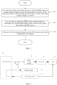
- FIG. 1 is a flowchart of a blood pressure detection method according to an embodiment of this application. As shown in FIG. 1 , the method includes the following steps.
- Step 101 In a case that a target user holds an area in which the PPG sensor is located, output a target torsion force through a reel motor of the electronic device, where the target torsion force is used to drive the rollable-display to unfold.
- the target torsion force can be understood as a driving force that can drive the rollable-display to unfold, that is, the target torsion force is greater than a static friction force of the rollable-display and can drive the rollable-display to enter the unfolded state.
- Step 102 In a case that an unfolding length of the rollable-display is maintained in a target length range, obtain a pulse wave signal detected by the PPG sensor.
- the target torsion force output by the reel motor is balanced with the holding force of the target user, so that the unfolding length of the rollable-display is maintained in a length range. That is, the relationship between the target torsion force and the holding force of the target user can be determined by detecting whether the unfolding length of the rollable-display is maintained in the target length range, and then the holding force of the user can be determined.
- the pressing force of the target user can be adjusted by controlling the target torsion force, so that the target user can maintain the pressing force within the pressure range required for blood pressure detection, and then the purpose of improving the accuracy of blood pressure detection can be achieved.
- the target torsion force in this application is used to maintain the pressing force of the target user within the pressure range required for blood pressure detection.
- the target torsion force output by the reel motor is in balance with the holding force of the target user (that is, the pressing force of the target user on the PPG sensor) by determining whether the unfolding length of the rollable-display is maintained in the target length range.
- the target torsion force output by the reel motor is in balance with the holding force of the target user, that is, the pressing force of the target user on the PPG sensor is within the pressure range required for blood pressure detection, thereby achieving the purpose of improving the accuracy of blood pressure detection.
- Step 103 Generate a blood pressure detection result of the target user based on the pulse wave signal.
- the blood pressure detection result includes a systolic blood pressure result and a diastolic blood pressure result
- the systolic blood pressure result and the diastolic blood pressure result can be calculated by fitting a virtual envelope curve based on the pulse wave signal.
- the holding power of the user can be maintained, based on the unfolding tension of the rollable-display of the rollable-display electronic device, within the pressure range required for blood pressure detection, so as to achieve the purpose of improving the accuracy of blood pressure detection.
- a pressure detection sensor is added to detect the pressing force of the user, and a component layout of the electronic device can be simplified.
- the target torsion force of different ranges can be set, and detection results corresponding to different ranges can be obtained. Then the virtual envelope curve is fitted based on the detection results of different ranges, and the systolic blood pressure result and the diastolic blood pressure result are finally obtained through the envelope curve, so as to improve the accuracy of blood pressure detection.
- the PPG sensor can collect pulse wave signals in the whole process, but in the process of generating detection results, only pulse wave signals that meet the condition are extracted to achieve the purpose of improving the accuracy of blood pressure detection.
- an embodiment of this application further provides a block diagram of an electronic device.
- the electronic device includes a control module 21, a rollable-display 22, a motor driving module 23, a reel motor 24, a reel 25, and a reel ranging sensor 26.
- the control module 21 is separately electrically connected to the rollable-display 22, the motor driving module 23, and the reel ranging sensor 26.
- the motor driving module 23 is electrically connected to the reel motor 24.
- the reel motor 24 is drivingly connected to the reel 25, and the reel ranging sensor 26 is arranged on the reel 25.
- the reel ranging sensor 26 is used to detect the unfolding length of the rollable-display 22. Specifically, the unfolding length of the rollable-display 22 can be calculated by detecting a distance between the PPG sensor and the reel 25.
- the reel motor 24 is used to drive the reel 25 to be unfolded or folded, so that the rollable-display can be switched between the unfolded state and the folded state.
- the reel ranging sensor 26 can form a closed-loop control with the rollable-display 22 through the control module 21, so as to display the detection result of the reel ranging sensor 26 in real time through the rollable-display 22.
- the obtaining a pulse wave signal detected by the PPG sensor includes: in a case that the unfolding length of the rollable-display is maintained in the target length range, and the unfolding length of the rollable-display is maintained in the target length range for duration exceeding a first preset time, obtaining a pulse wave signal detected by the PPG sensor in a time period corresponding to the first preset time.
- a first preset time for example, 10 seconds
- the method further includes:
- the change of the unfolding length of the rollable-display can be detected by using the reel ranging sensor shown in FIG. 2 .
- the unfolding length of the rollable-display meets the preset condition, it can be understood that the unfolding length of the rollable-display is not maintained within the target length range, that is, the holding force of the target user is too large or too small relative to the target torsion force.
- prompt information is used to instruct the target user to increase the holding power and maintain the unfolding length of the rollable-display in the target length range, that is, maintain the rollable-display from unfolding and folding.
- the prompt information is used to instruct the target user to reduce the holding power and maintain the unfolding length of the rollable-display in the target length range, that is, maintain the rollable-display from unfolding and folding.
- the prompt information is used to instruct the target user to maintain the holding power and maintain the rollable-display from unfolding and folding.
- the prompt information can be output by voice playing to instruct the user to perform corresponding operations.
- the method further includes:
- the blood pressure detection information in real time, especially the information such as the curve diagram of the target torsion force and the holding force of the target user, the countdown diagram of maintaining the holding force by the target user, the holding operation diagram, and the prompt information, it is convenient for the target user to adjust the blood pressure detection operation in time and improve the blood pressure detection experience of the user.
- the detection duration can be set to 10 seconds, that is, the duration for the user to maintain the holding power can be set to 10 seconds, and the countdown diagram of maintaining the holding force by the target user can be displayed on the rollable-display, so that the user can maintain the holding power, thereby achieving the purpose of improving the accuracy of the detection result.
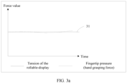
- a curve diagram 31 of the target torsion force and the holding force of the target user can be displayed on the display interface of the rollable-display.
- a holding operation diagram 32 and the prompt information 33 can also be displayed on the display interface of the rollable-display.
- a target torsion force is output through a reel motor of the electronic device, where the target torsion force is used to drive the rollable-display to unfold; in a case that an unfolding length of the rollable-display is maintained in a target length range, a pulse wave signal detected by the PPG sensor is obtained; and a blood pressure detection result of the target user is generated based on the pulse wave signal.
- the holding power of the user can be maintained, based on the unfolding tension of the rollable-display of the rollable-display electronic device, within the pressure range required for blood pressure detection, so as to achieve the purpose of improving the accuracy of blood pressure detection.
- the blood pressure detection method provided in this embodiment of this application may be executed by a blood pressure detection apparatus.
- the blood pressure detection apparatus provided in the embodiments of this application is described by using an example in which the blood pressure detection method is performed by the blood pressure detection apparatus.
- FIG. 4 is a structural diagram of a blood pressure detection apparatus according to an embodiment of this application.
- the apparatus 400 is applied to an electronic device, the electronic device is a rollable-display electronic device including a housing assembly, a rollable-display, and a PPG sensor, the PPG sensor is arranged on a frame of the housing assembly distributed along an unfolding direction of the rollable-display, and the apparatus 400 includes:
- the obtaining module 402 is specifically configured to: in a case that the unfolding length of the rollable-display is maintained in the target length range, and the unfolding length of the rollable-display is maintained in the target length range for duration exceeding a first preset time, obtain a pulse wave signal detected by the PPG sensor in a time period corresponding to the first preset time.
- the apparatus 400 further includes:
- the apparatus 400 further includes:
- the second output module is specifically configured to output prompt information by voice playing.
- the blood pressure detection apparatus in this embodiment of this application may be an electronic device, or may be a component such as a circuit or a chip in the electronic device.
- the electronic device may be a terminal, or another device other than the terminal.
- the electronic device may be a mobile phone, a tablet computer, a notebook computer, a palmtop computer, an in-vehicle electronic device, a mobile Internet device (Mobile Internet Device, MID), an augmented reality (Augmented Reality, AR)/virtual reality (Virtual Reality, VR) device, a robot, a wearable device, an ultra-mobile personal computer (Ultra-Mobile Personal Computer, UMPC), a netbook, a personal digital assistant (Personal Digital Assistant, PDA), or the like.
- the electronic device may be alternatively a network attached storage (Network Attached Storage, NAS), a personal computer (Personal Computer, PC), a television (Television, TV), a teller machine, a self-service machine, or the like. This is not specifically limited in this embodiment of this application.
- Network Attached Storage NAS
- PC Personal Computer
- TV Television
- teller machine a self-service machine, or the like. This is not specifically limited in this embodiment of this application.
- the blood pressure detection apparatus in this embodiment of this application may be an apparatus with an operating system.
- the operating system may be an Android (Android) operating system, may be an iOS operating system, or may be another possible operating system. This is not specifically limited in this embodiment of this application.
- the blood pressure detection apparatus provided in this embodiment of this application can implement processes implemented in the method embodiments from FIG. 1 to FIG. 3 . To avoid repetition, details are not described herein again.
- an embodiment of this application further provides an electronic device 500, including a processor 501 and a memory 502, and the memory 502 stores a program or an instruction that can be run on the processor 501.
- the program or the instruction is executed by the processor 501, the steps of the foregoing embodiment of the blood pressure detection method are implemented, and a same technical effect can be achieved. To avoid repetition, details are not described herein again.
- the electronic device in this embodiment of this application includes the foregoing mobile electronic device and the foregoing non-mobile electronic device.
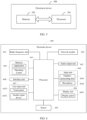
- FIG. 6 is a structural diagram of an electronic device according to an embodiment of this application.
- the electronic device 600 includes, but not limited to: a radio frequency unit 601, a network module 602, an audio output unit 603, an input unit 604, a sensor 605, a display unit 606, a user input unit 607, an interface unit 608, a memory 609, a processor 610, and the like.
- the electronic device 600 may further include a power supply (such as a battery) that supplies power to each component.
- the power supply may be logically connected to the processor 610 by using a power supply management system, to implement functions such as charging and discharging management, and power consumption management by using the power supply management system.
- the structure of the electronic device shown in FIG. 6 does not constitute a limitation on the electronic device.
- the electronic device may include components more or fewer than those shown in the diagram, a combination of some components, or different component arrangements. Details are not described herein.
- the processor 610 is configured to: in a case that a target user holds an area in which the PPG sensor is located, output a target torsion force through a reel motor of the electronic device, where the target torsion force is used to drive the rollable-display to unfold; in a case that an unfolding length of the rollable-display is maintained in a target length range, obtain a pulse wave signal detected by the PPG sensor; and generate a blood pressure detection result of the target user based on the pulse wave signal.
- the processor 610 is configured to: in a case that the unfolding length of the rollable-display is maintained in the target length range, and the unfolding length of the rollable-display is maintained in the target length range for duration exceeding a first preset time, obtain a pulse wave signal detected by the PPG sensor in a time period corresponding to the first preset time.
- the senor 605 is configured to detect a change of the unfolding length of the rollable-display; and the processor 610 is configured to: in a case that the change of the unfolding length meets a preset condition, output prompt information, where the prompt information is used to remind the target user to adjust a holding force and maintain the unfolding length of the rollable-display in the target length range.
- the display unit 606 is configured to display blood pressure detection information on the rollable-display, where the blood pressure detection information includes at least one of the following:
- the audio output unit 603 is configured to output prompt information by voice playing.
- the input unit 604 may include a graphics processing unit (Graphics Processing Unit, GPU) 6041 and a microphone 6042.
- the graphics processing unit 6041 processes image data of a static picture or a video obtained by an image capture apparatus (for example, a camera) in a video capture mode or an image capture mode.
- the display unit 606 may include a display panel 6061, and the display panel 6061 may be configured in a form of a liquid crystal display, an organic light-emitting diode, or the like.
- the user input unit 607 includes at least one of a touch panel 6071 and another input device 6072.
- the touch panel 6071 is also referred to as a touchscreen.
- the touch panel 6071 may include two parts: a touch detection apparatus and a touch controller.
- the another input device 6072 may include but is not limited to a physical keyboard, a functional button (such as a volume control button or a power on/off button), a trackball, a mouse, and a joystick. Details are not described herein.
- the memory 609 may be configured to store a software program and various data.
- the memory 609 may mainly include a first storage area for storing a program or an instruction and a second storage area for storing data.
- the first storage area may store an operating system, and an application or an instruction required by at least one function (for example, a sound playing function or an image playing function).
- the memory 609 may be a volatile memory or a non-volatile memory, or the memory 609 may include a volatile memory and a non-volatile memory.
- the non-volatile memory may be a read-only memory (Read-Only Memory, ROM), a programmable read-only memory (Programmable ROM, PROM), an erasable programmable read-only memory (Erasable PROM, EPROM), an electrically erasable programmable read-only memory (Electrically EPROM, EEPROM), or a flash memory.
- ROM Read-Only Memory
- PROM programmable read-only memory
- Erasable PROM Erasable PROM
- EPROM electrically erasable programmable read-only memory
- EEPROM electrically erasable programmable read-only memory
- the volatile memory may be a random access memory (Random Access Memory, RAM), a static random access memory (Static RAM, SRAM), a dynamic random access memory (Dynamic RAM, DRAM), a synchronous dynamic random access memory (Synchronous DRAM, SDRAM), a double data rate synchronous dynamic random access memory (Double Data Rate SDRAM, DDRSDRAM), an enhanced synchronous dynamic random access memory (Enhanced SDRAM, ESDRAM), a synchlink dynamic random access memory (Synchlink DRAM, SLDRAM), and a direct rambus random access memory (Direct Rambus RAM, DRRAM).
- RAM Random Access Memory
- SRAM static random access memory
- DRAM dynamic random access memory
- DRAM synchronous dynamic random access memory
- SDRAM double data rate synchronous dynamic random access memory
- Enhanced SDRAM, ESDRAM enhanced synchronous dynamic random access memory
- Synchlink dynamic random access memory Synchlink dynamic random access memory
- SLDRAM direct rambus random access memory
- Direct Rambus RAM Direct Rambus RAM
- the processor 610 may include one or more processing units.
- an application processor and a modem processor are integrated into the processor 610.
- the application processor mainly processes an operating system, a user interface, an application, or the like.
- the modem processor mainly processes a wireless communication signal, for example, a baseband processor. It may be understood that, alternatively, the modem processor may not be integrated into the processor 610.
- An embodiment of this application further provides a readable storage medium.
- the readable storage medium stores a program or an instruction.
- the program or the instruction is executed by a processor, the processes of the foregoing blood pressure detection method embodiment are implemented, and same technical effect can be achieved. To avoid repetition, details are not described herein again.
- the processor is a processor in the electronic device in the foregoing embodiment.
- the readable storage medium includes a computer-readable storage medium, such as a computer read-only memory ROM, a random access memory RAM, a magnetic disk, or an optical disc.
- An embodiment of this application further provides a chip.
- the chip includes a processor and a communications interface, the communications interface is coupled to the processor, and the processor is configured to run a program or an instruction to implement the processes of the foregoing blood pressure detection method embodiment, and same technical effect can be achieved. To avoid repetition, details are not described herein again.
- the chip mentioned in this embodiment of this application may also be referred to as a system-level chip, a system chip, a chip system, an on-chip system chip, or the like.
- An embodiment of this application provides a computer program product.
- the program product is stored in a storage medium.
- the program product is executed by at least one processor to implement the processes of the foregoing blood pressure detection method embodiment, and same technical effect can be achieved. To avoid repetition, details are not described herein again.
- the method in the foregoing embodiment may be implemented by software in addition to a necessary universal hardware platform or by hardware only. In most circumstances, the former is a preferred implementation. Based on such an understanding, the technical solutions of this application essentially or the part contributing to the prior art may be implemented in a form of a computer software product.
- the computer software product is stored in a storage medium (for example, a ROM/RAM, a floppy disk, or an optical disc), and includes several instructions for instructing a terminal (which may be a mobile phone, a computer, a server, a network device, or the like) to perform the methods described in the embodiments of this application.
Landscapes
- Health & Medical Sciences (AREA)
- Life Sciences & Earth Sciences (AREA)
- Engineering & Computer Science (AREA)
- Surgery (AREA)
- General Health & Medical Sciences (AREA)
- Veterinary Medicine (AREA)
- Biomedical Technology (AREA)
- Public Health (AREA)
- Medical Informatics (AREA)
- Molecular Biology (AREA)
- Heart & Thoracic Surgery (AREA)
- Animal Behavior & Ethology (AREA)
- Pathology (AREA)
- Biophysics (AREA)
- Physics & Mathematics (AREA)
- Cardiology (AREA)
- Vascular Medicine (AREA)
- Physiology (AREA)
- Nuclear Medicine, Radiotherapy & Molecular Imaging (AREA)
- Multimedia (AREA)
- Radiology & Medical Imaging (AREA)
- Oral & Maxillofacial Surgery (AREA)
- Measuring Pulse, Heart Rate, Blood Pressure Or Blood Flow (AREA)
Abstract
Description
- This application claims priority to
Chinese Patent Application No. 202210088537.2, filed on January 25, 2022 - This application pertains to the field of blood pressure detection technologies, and in particular, to a blood pressure detection method and apparatus, and an electronic device.
- With the development of technology, more and more manufacturers select to integrate photoplethysmograph (photoplethysmograph, PPG) sensors on electronic devices such as smart phones, so that users can detect blood pressure changes through electronic devices.
- However, compared with the pressure sensor on the conventional cuff blood pressure detector, the blood pressure detection scheme of the PPG sensor using the electronic device lacks an air pump to provide appropriate pressure, which makes it difficult for users to control the pressing pressure within the pressure range required for blood pressure detection, and further leads to the decline of detection accuracy.
- It can be seen that the blood pressure detection scheme in the related art has the problem of low detection accuracy.
- Embodiments of this application are intended to provide a blood pressure detection method and apparatus, and an electronic device, which can solve the problem of low detection accuracy in the blood pressure detection scheme in the related art.
- According to a first aspect, an embodiment of this application provides a blood pressure detection method, applied to an electronic device, where the electronic device is a rollable-display electronic device including a housing assembly, a rollable-display, and a photoplethysmograph (PPG) sensor, the PPG sensor is arranged on a frame of the housing assembly distributed along an unfolding direction of the rollable-display, and the method includes:
- in a case that a target user holds an area in which the PPG sensor is located, outputting a target torsion force through a reel motor of the electronic device, where the target torsion force is used to drive the rollable-display to unfold;
- in a case that an unfolding length of the rollable-display is maintained in a target length range, obtaining a pulse wave signal detected by the PPG sensor; and
- generating a blood pressure detection result of the target user based on the pulse wave signal.
- According to a second aspect, an embodiment of this application provides a blood pressure detection apparatus, applied to an electronic device, where the electronic device is a rollable-display electronic device including a housing assembly, a rollable-display, and a PPG sensor, the PPG sensor is arranged on a frame of the housing assembly distributed along an unfolding direction of the rollable-display, and the apparatus includes:
- a first output module, configured to: in a case that a target user holds an area in which the PPG sensor is located, output a target torsion force through a reel motor of the electronic device, where the target torsion force is used to drive the rollable-display to unfold;
- an obtaining module, configured to: in a case that an unfolding length of the rollable-display is maintained in a target length range, obtain a pulse wave signal detected by the PPG sensor; and
- a generating module, configured to generate a blood pressure detection result of the target user based on the pulse wave signal.
- According to a third aspect, an embodiment of this application provides an electronic device, where the electronic device includes a processor and a memory, the memory stores a program or an instruction that can run on the processor, and when the program or the instruction is executed by the processor, the steps of the method according to the first aspect are implemented.
- According to a fourth aspect, an embodiment of this application provides a readable storage medium. The readable storage medium stores a program or an instruction, where when the program or the instruction is executed by a processor, the steps of the method according to the first aspect are implemented.
- According to a fifth aspect, an embodiment of this application provides a chip. The chip includes a processor and a communications interface, the communications interface is coupled to the processor, and the processor is configured to run a program or an instruction to implement the method according to the first aspect.
- According to a sixth aspect, an embodiment of this application provides a computer program product. The program product is stored in a storage medium, and the program product is executed by at least one processor to implement the method according to the first aspect.
- In the embodiments of this application, in a case that a target user holds an area in which the PPG sensor is located, a target torsion force is output through a reel motor of the electronic device, where the target torsion force is used to drive the rollable-display to unfold; in a case that an unfolding length of the rollable-display is maintained in a target length range, a pulse wave signal detected by the PPG sensor is obtained; and a blood pressure detection result of the target user is generated based on the pulse wave signal. In this way, by using the characteristics of the rollable-display electronic device, the holding power of the user can be maintained, based on the unfolding tension of the rollable-display of the rollable-display electronic device, within the pressure range required for blood pressure detection, so as to achieve the purpose of improving the accuracy of blood pressure detection.
-
-
FIG. 1 is a flowchart of a blood pressure detection method according to an embodiment of this application; -
FIG. 2 is a structural diagram of an electronic device according to an embodiment of this application; -
FIG. 3a is a first schematic diagram of blood pressure detection operations according to an embodiment of this application; -
FIG. 3b is a second schematic diagram of blood pressure detection operations according to an embodiment of this application; -
FIG. 4 is a structural diagram of a blood pressure detection apparatus according to an embodiment of this application; -
FIG. 5 is a structural diagram of an electronic device according to another embodiment of this application; and -
FIG. 6 is a structural diagram of an electronic device according to still another embodiment of this application. - The following clearly and completely describes the technical solutions in the embodiments of this application with reference to the accompanying drawings in the embodiments of this application. Apparently, the described embodiments are some but not all of the embodiments of this application. All other embodiments obtained by a person of ordinary skill in the art based on the embodiments of this application without creative efforts shall fall within the protection scope of this application.
- In the specification and claims of this application, the terms such as "first" and "second" are used for distinguishing similar objects, and are not necessarily used to describe a particular order or sequence. It should be understood that terms used in such a way are interchangeable in proper circumstances, so that embodiments of this application can be implemented in an order other than the order illustrated or described herein. Objects classified by "first", "second", and the like are usually of a same type, and a quantity of objects is not limited. For example, there may be one or more first objects. In addition, in this specification and the claims, "and/or" indicates at least one of connected objects, and a character "/" generally indicates an "or" relationship between associated objects.
- With reference to the accompanying drawings, the blood pressure detection method provided in the embodiments of this application is described in detail by using specific embodiments and application scenarios thereof.
- The blood pressure detection method provided in the embodiments of this application is applied to an electronic device, where the electronic device is a rollable-display electronic device including a housing assembly, a rollable-display, and a PPG sensor, the PPG sensor is arranged on a frame of the housing assembly distributed along an unfolding direction of the rollable-display.
- Optionally, the housing assembly includes a first housing and a second housing, the first housing and the second housing are connected in a sliding way, one end of the rollable-display is connected to the first housing, and the other end of the rollable-display is connected to the second housing. Driven by a reel motor, the rollable-display is retractable and can be switched between an unfolded state and a folded state.
- In the unfolding process of the rollable-display, the first housing and/or the second housing can be driven by the reel motor to move, and then the rollable-display is driven to unfold. It is also possible to drive the rollable-display to unfold through the reel motor, and then drive the first housing and the second housing to move in opposite directions, so as to realize the unfolding process of the rollable-display.
- The PPG sensor is used for the pulse wave signal in the arterial capillary of the user, and the detected pulse wave signal can be calculated to obtain corresponding systolic and diastolic blood pressure results based on a corresponding algorithm, that is, corresponding blood pressure detection results can be calculated.
- In this application, in the process of blood pressure detection, the user can hold a position where the PPG sensor is arranged in the housing assembly. Moreover, in order to facilitate the user to quickly locate the PPG sensor on the housing assembly, a reminder sign, such as "PPG", can also be displayed at the position where the PPG sensor is arranged on the housing assembly to remind the user.
- Referring to
FIG. 1, FIG. 1 is a flowchart of a blood pressure detection method according to an embodiment of this application. As shown inFIG. 1 , the method includes the following steps. -
Step 101. In a case that a target user holds an area in which the PPG sensor is located, output a target torsion force through a reel motor of the electronic device, where the target torsion force is used to drive the rollable-display to unfold. - In this step, the target torsion force can be understood as a driving force that can drive the rollable-display to unfold, that is, the target torsion force is greater than a static friction force of the rollable-display and can drive the rollable-display to enter the unfolded state.
-
Step 102. In a case that an unfolding length of the rollable-display is maintained in a target length range, obtain a pulse wave signal detected by the PPG sensor. - In this step, in a case that the unfolding length of the rollable-display is maintained in the target length range, it can be understood that the target torsion force output by the reel motor is balanced with the holding force of the target user, so that the unfolding length of the rollable-display is maintained in a length range. That is, the relationship between the target torsion force and the holding force of the target user can be determined by detecting whether the unfolding length of the rollable-display is maintained in the target length range, and then the holding force of the user can be determined.
- Because in the process of blood pressure detection, the target user needs to maintain the pressing force within the pressure range required for blood pressure detection, to improve the accuracy of blood pressure detection, the pressing force of the target user can be adjusted by controlling the target torsion force, so that the target user can maintain the pressing force within the pressure range required for blood pressure detection, and then the purpose of improving the accuracy of blood pressure detection can be achieved.
- It can be understood that the target torsion force in this application is used to maintain the pressing force of the target user within the pressure range required for blood pressure detection.
- Specifically, it can be determined whether the target torsion force output by the reel motor is in balance with the holding force of the target user (that is, the pressing force of the target user on the PPG sensor) by determining whether the unfolding length of the rollable-display is maintained in the target length range. When it is determined that the unfolding length of the rollable-display is maintained in the target length range, it is determined that the target torsion force output by the reel motor is in balance with the holding force of the target user, that is, the pressing force of the target user on the PPG sensor is within the pressure range required for blood pressure detection, thereby achieving the purpose of improving the accuracy of blood pressure detection.
-
Step 103. Generate a blood pressure detection result of the target user based on the pulse wave signal. - In this step, the blood pressure detection result includes a systolic blood pressure result and a diastolic blood pressure result, and the systolic blood pressure result and the diastolic blood pressure result can be calculated by fitting a virtual envelope curve based on the pulse wave signal.
- In this way, by using the characteristics of the rollable-display electronic device, the holding power of the user can be maintained, based on the unfolding tension of the rollable-display of the rollable-display electronic device, within the pressure range required for blood pressure detection, so as to achieve the purpose of improving the accuracy of blood pressure detection.
- Moreover, compared with the electronic device in the related art, a pressure detection sensor is added to detect the pressing force of the user, and a component layout of the electronic device can be simplified.
- Because the pressure required for blood pressure detection is a range, the target torsion force of different ranges can be set, and detection results corresponding to different ranges can be obtained. Then the virtual envelope curve is fitted based on the detection results of different ranges, and the systolic blood pressure result and the diastolic blood pressure result are finally obtained through the envelope curve, so as to improve the accuracy of blood pressure detection.
- In the process of blood pressure detection, the PPG sensor can collect pulse wave signals in the whole process, but in the process of generating detection results, only pulse wave signals that meet the condition are extracted to achieve the purpose of improving the accuracy of blood pressure detection.
- As shown in
FIG. 2 , an embodiment of this application further provides a block diagram of an electronic device. The electronic device includes acontrol module 21, a rollable-display 22, amotor driving module 23, areel motor 24, areel 25, and areel ranging sensor 26. - The
control module 21 is separately electrically connected to the rollable-display 22, themotor driving module 23, and thereel ranging sensor 26. Themotor driving module 23 is electrically connected to thereel motor 24. - The
reel motor 24 is drivingly connected to thereel 25, and thereel ranging sensor 26 is arranged on thereel 25. - The
reel ranging sensor 26 is used to detect the unfolding length of the rollable-display 22. Specifically, the unfolding length of the rollable-display 22 can be calculated by detecting a distance between the PPG sensor and thereel 25. - The
reel motor 24 is used to drive thereel 25 to be unfolded or folded, so that the rollable-display can be switched between the unfolded state and the folded state. - In some implementations, the
reel ranging sensor 26 can form a closed-loop control with the rollable-display 22 through thecontrol module 21, so as to display the detection result of thereel ranging sensor 26 in real time through the rollable-display 22. - Optionally, in a case that an unfolding length of the rollable-display is maintained in a target length range, the obtaining a pulse wave signal detected by the PPG sensor includes:
in a case that the unfolding length of the rollable-display is maintained in the target length range, and the unfolding length of the rollable-display is maintained in the target length range for duration exceeding a first preset time, obtaining a pulse wave signal detected by the PPG sensor in a time period corresponding to the first preset time. - In this implementation, it is determined whether the target torsion force output by the reel motor is in balance with the holding force of the target user by determining the duration that the unfolding length of the rollable-display is maintained in the target length range, and it is determined that the target torsion force output by the reel motor is in balance with the holding force of the target user when the unfolding length of the rollable-display is maintained in the target length range for duration exceeding a first preset time (for example, 10 seconds), so as to improve the accuracy of the pulse wave signal detected by the PPG sensor and further achieve the purpose of improving the accuracy of blood pressure detection.
- Optionally, after the outputting a target torsion force through a reel motor of the electronic device, in a case that an unfolding length of the rollable-display is maintained in a target length range, before the obtaining a pulse wave signal detected by the PPG sensor, the method further includes:
- detecting a change of the unfolding length of the rollable-display; and
- in a case that the change of the unfolding length meets a preset condition, outputting prompt information, where the prompt information is used to remind the target user to adjust a holding force and maintain the unfolding length of the rollable-display in the target length range.
- In this implementation, it can be determined whether the unfolding length of the rollable-display is maintained in the target length range by detecting the change of the unfolding length of the rollable-display, and then whether the target torsion force output by the reel motor is in balance with the holding force of the target user is determined.
- In some implementations, the change of the unfolding length of the rollable-display can be detected by using the reel ranging sensor shown in
FIG. 2 . - When the change of the unfolding length of the rollable-display meets the preset condition, it can be understood that the unfolding length of the rollable-display is not maintained within the target length range, that is, the holding force of the target user is too large or too small relative to the target torsion force.
- Specifically, when the change of the unfolding length of the rollable-display indicates that the unfolding length of the rollable-display is greater than a maximum length of the target length range, prompt information is used to instruct the target user to increase the holding power and maintain the unfolding length of the rollable-display in the target length range, that is, maintain the rollable-display from unfolding and folding. Accordingly, when the change of the unfolding length of the rollable-display indicates that the unfolding length of the rollable-display is less than a minimum length of the target length range, the prompt information is used to instruct the target user to reduce the holding power and maintain the unfolding length of the rollable-display in the target length range, that is, maintain the rollable-display from unfolding and folding.
- In addition, when the change of the unfolding length of the rollable-display indicates that the unfolding length of the rollable-display is maintained within the target length range, the prompt information is used to instruct the target user to maintain the holding power and maintain the rollable-display from unfolding and folding.
- The prompt information can be output by voice playing to instruct the user to perform corresponding operations.
- Optionally, the method further includes:
- displaying blood pressure detection information on the rollable-display, where
- the blood pressure detection information includes at least one of the following:
- a curve diagram of the target torsion force and the holding force of the target user;
- a countdown diagram of maintaining the holding force by the target user;
- a holding operation diagram; and
- the prompt information.
- In this implementation, by displaying the blood pressure detection information in real time, especially the information such as the curve diagram of the target torsion force and the holding force of the target user, the countdown diagram of maintaining the holding force by the target user, the holding operation diagram, and the prompt information, it is convenient for the target user to adjust the blood pressure detection operation in time and improve the blood pressure detection experience of the user.
- In some embodiments, the detection duration can be set to 10 seconds, that is, the duration for the user to maintain the holding power can be set to 10 seconds, and the countdown diagram of maintaining the holding force by the target user can be displayed on the rollable-display, so that the user can maintain the holding power, thereby achieving the purpose of improving the accuracy of the detection result.
- As shown in
FIG. 3a , a curve diagram 31 of the target torsion force and the holding force of the target user can be displayed on the display interface of the rollable-display. As shown inFIG. 3b , a holding operation diagram 32 and theprompt information 33 can also be displayed on the display interface of the rollable-display. - According to the blood pressure detection method provided in the embodiments of this application, in a case that a target user holds an area in which the PPG sensor is located, a target torsion force is output through a reel motor of the electronic device, where the target torsion force is used to drive the rollable-display to unfold; in a case that an unfolding length of the rollable-display is maintained in a target length range, a pulse wave signal detected by the PPG sensor is obtained; and a blood pressure detection result of the target user is generated based on the pulse wave signal. In this way, by using the characteristics of the rollable-display electronic device, the holding power of the user can be maintained, based on the unfolding tension of the rollable-display of the rollable-display electronic device, within the pressure range required for blood pressure detection, so as to achieve the purpose of improving the accuracy of blood pressure detection.
- The blood pressure detection method provided in this embodiment of this application may be executed by a blood pressure detection apparatus. In this embodiment of this application, the blood pressure detection apparatus provided in the embodiments of this application is described by using an example in which the blood pressure detection method is performed by the blood pressure detection apparatus.
- Referring to
FIG. 4, FIG. 4 is a structural diagram of a blood pressure detection apparatus according to an embodiment of this application. As shown inFIG. 4 , theapparatus 400 is applied to an electronic device, the electronic device is a rollable-display electronic device including a housing assembly, a rollable-display, and a PPG sensor, the PPG sensor is arranged on a frame of the housing assembly distributed along an unfolding direction of the rollable-display, and theapparatus 400 includes: - a
first output module 401, configured to: in a case that a target user holds an area in which the PPG sensor is located, output a target torsion force through a reel motor of the electronic device, where the target torsion force is used to drive the rollable-display to unfold; - an obtaining
module 402, configured to: in a case that an unfolding length of the rollable-display is maintained in a target length range, obtain a pulse wave signal detected by the PPG sensor; and - a
generating module 403, configured to generate a blood pressure detection result of the target user based on the pulse wave signal. - Optionally, the obtaining
module 402 is specifically configured to: in a case that the unfolding length of the rollable-display is maintained in the target length range, and the unfolding length of the rollable-display is maintained in the target length range for duration exceeding a first preset time, obtain a pulse wave signal detected by the PPG sensor in a time period corresponding to the first preset time. - Optionally, the
apparatus 400 further includes: - a detecting module, configured to detect a change of the unfolding length of the rollable-display; and
- a second output module, configured to: in a case that the change of the unfolding length meets a preset condition, output prompt information, where the prompt information is used to remind the target user to adjust a holding force and maintain the unfolding length of the rollable-display in the target length range.
- Optionally, the
apparatus 400 further includes: - a display module, configured to display blood pressure detection information on the rollable-display, where
- the blood pressure detection information includes at least one of the following:
- a curve diagram of the target torsion force and the holding force of the target user;
- a countdown diagram of maintaining the holding force by the target user;
- a holding operation diagram; and
- the prompt information.
- Optionally, the second output module is specifically configured to output prompt information by voice playing.
- The blood pressure detection apparatus in this embodiment of this application may be an electronic device, or may be a component such as a circuit or a chip in the electronic device. The electronic device may be a terminal, or another device other than the terminal. For example, the electronic device may be a mobile phone, a tablet computer, a notebook computer, a palmtop computer, an in-vehicle electronic device, a mobile Internet device (Mobile Internet Device, MID), an augmented reality (Augmented Reality, AR)/virtual reality (Virtual Reality, VR) device, a robot, a wearable device, an ultra-mobile personal computer (Ultra-Mobile Personal Computer, UMPC), a netbook, a personal digital assistant (Personal Digital Assistant, PDA), or the like. The electronic device may be alternatively a network attached storage (Network Attached Storage, NAS), a personal computer (Personal Computer, PC), a television (Television, TV), a teller machine, a self-service machine, or the like. This is not specifically limited in this embodiment of this application.
- The blood pressure detection apparatus in this embodiment of this application may be an apparatus with an operating system. The operating system may be an Android (Android) operating system, may be an iOS operating system, or may be another possible operating system. This is not specifically limited in this embodiment of this application.
- The blood pressure detection apparatus provided in this embodiment of this application can implement processes implemented in the method embodiments from
FIG. 1 to FIG. 3 . To avoid repetition, details are not described herein again. - Optionally, as shown in
FIG. 5 , an embodiment of this application further provides anelectronic device 500, including aprocessor 501 and amemory 502, and thememory 502 stores a program or an instruction that can be run on theprocessor 501. When the program or the instruction is executed by theprocessor 501, the steps of the foregoing embodiment of the blood pressure detection method are implemented, and a same technical effect can be achieved. To avoid repetition, details are not described herein again. - It should be noted that the electronic device in this embodiment of this application includes the foregoing mobile electronic device and the foregoing non-mobile electronic device.
- Referring to
FIG. 6, FIG. 6 is a structural diagram of an electronic device according to an embodiment of this application. As shown inFIG. 6 , theelectronic device 600 includes, but not limited to: aradio frequency unit 601, anetwork module 602, anaudio output unit 603, aninput unit 604, asensor 605, adisplay unit 606, auser input unit 607, aninterface unit 608, amemory 609, aprocessor 610, and the like. - A person skilled in the art can understand that the
electronic device 600 may further include a power supply (such as a battery) that supplies power to each component. The power supply may be logically connected to theprocessor 610 by using a power supply management system, to implement functions such as charging and discharging management, and power consumption management by using the power supply management system. The structure of the electronic device shown inFIG. 6 does not constitute a limitation on the electronic device. The electronic device may include components more or fewer than those shown in the diagram, a combination of some components, or different component arrangements. Details are not described herein. - The
processor 610 is configured to: in a case that a target user holds an area in which the PPG sensor is located, output a target torsion force through a reel motor of the electronic device, where the target torsion force is used to drive the rollable-display to unfold; in a case that an unfolding length of the rollable-display is maintained in a target length range, obtain a pulse wave signal detected by the PPG sensor; and generate a blood pressure detection result of the target user based on the pulse wave signal. - Optionally, the
processor 610 is configured to: in a case that the unfolding length of the rollable-display is maintained in the target length range, and the unfolding length of the rollable-display is maintained in the target length range for duration exceeding a first preset time, obtain a pulse wave signal detected by the PPG sensor in a time period corresponding to the first preset time. - Optionally, the
sensor 605 is configured to detect a change of the unfolding length of the rollable-display; and
theprocessor 610 is configured to: in a case that the change of the unfolding length meets a preset condition, output prompt information, where the prompt information is used to remind the target user to adjust a holding force and maintain the unfolding length of the rollable-display in the target length range. - Optionally, the
display unit 606 is configured to display blood pressure detection information on the rollable-display, where
the blood pressure detection information includes at least one of the following: - a curve diagram of the target torsion force and the holding force of the target user;
- a countdown diagram of maintaining the holding force by the target user;
- a holding operation diagram; and
- the prompt information.
- Optionally, the
audio output unit 603 is configured to output prompt information by voice playing. - It should be understood that in this embodiment of this application, the
input unit 604 may include a graphics processing unit (Graphics Processing Unit, GPU) 6041 and amicrophone 6042. Thegraphics processing unit 6041 processes image data of a static picture or a video obtained by an image capture apparatus (for example, a camera) in a video capture mode or an image capture mode. Thedisplay unit 606 may include adisplay panel 6061, and thedisplay panel 6061 may be configured in a form of a liquid crystal display, an organic light-emitting diode, or the like. Theuser input unit 607 includes at least one of atouch panel 6071 and anotherinput device 6072. Thetouch panel 6071 is also referred to as a touchscreen. Thetouch panel 6071 may include two parts: a touch detection apparatus and a touch controller. The anotherinput device 6072 may include but is not limited to a physical keyboard, a functional button (such as a volume control button or a power on/off button), a trackball, a mouse, and a joystick. Details are not described herein. - The
memory 609 may be configured to store a software program and various data. Thememory 609 may mainly include a first storage area for storing a program or an instruction and a second storage area for storing data. The first storage area may store an operating system, and an application or an instruction required by at least one function (for example, a sound playing function or an image playing function). In addition, thememory 609 may be a volatile memory or a non-volatile memory, or thememory 609 may include a volatile memory and a non-volatile memory. The non-volatile memory may be a read-only memory (Read-Only Memory, ROM), a programmable read-only memory (Programmable ROM, PROM), an erasable programmable read-only memory (Erasable PROM, EPROM), an electrically erasable programmable read-only memory (Electrically EPROM, EEPROM), or a flash memory. The volatile memory may be a random access memory (Random Access Memory, RAM), a static random access memory (Static RAM, SRAM), a dynamic random access memory (Dynamic RAM, DRAM), a synchronous dynamic random access memory (Synchronous DRAM, SDRAM), a double data rate synchronous dynamic random access memory (Double Data Rate SDRAM, DDRSDRAM), an enhanced synchronous dynamic random access memory (Enhanced SDRAM, ESDRAM), a synchlink dynamic random access memory (Synchlink DRAM, SLDRAM), and a direct rambus random access memory (Direct Rambus RAM, DRRAM). Thememory 609 in this embodiment of this application includes but is not limited to these memories and any memory of another proper type. - The
processor 610 may include one or more processing units. Optionally, an application processor and a modem processor are integrated into theprocessor 610. The application processor mainly processes an operating system, a user interface, an application, or the like. The modem processor mainly processes a wireless communication signal, for example, a baseband processor. It may be understood that, alternatively, the modem processor may not be integrated into theprocessor 610. - An embodiment of this application further provides a readable storage medium. The readable storage medium stores a program or an instruction. When the program or the instruction is executed by a processor, the processes of the foregoing blood pressure detection method embodiment are implemented, and same technical effect can be achieved. To avoid repetition, details are not described herein again.
- The processor is a processor in the electronic device in the foregoing embodiment. The readable storage medium includes a computer-readable storage medium, such as a computer read-only memory ROM, a random access memory RAM, a magnetic disk, or an optical disc.
- An embodiment of this application further provides a chip. The chip includes a processor and a communications interface, the communications interface is coupled to the processor, and the processor is configured to run a program or an instruction to implement the processes of the foregoing blood pressure detection method embodiment, and same technical effect can be achieved. To avoid repetition, details are not described herein again.
- It should be understood that the chip mentioned in this embodiment of this application may also be referred to as a system-level chip, a system chip, a chip system, an on-chip system chip, or the like.
- An embodiment of this application provides a computer program product. The program product is stored in a storage medium. The program product is executed by at least one processor to implement the processes of the foregoing blood pressure detection method embodiment, and same technical effect can be achieved. To avoid repetition, details are not described herein again.
- It should be noted that, in this specification, the term "include", "comprise", or any other variant thereof is intended to cover a non-exclusive inclusion, so that a process, a method, an article, or an apparatus that includes a list of elements not only includes those elements but also includes other elements which are not expressly listed, or further includes elements inherent to this process, method, article, or apparatus. In absence of more constraints, an element preceded by "includes a..." does not preclude the existence of other identical elements in the process, method, article, or apparatus that includes the element. In addition, it should be noted that the scope of the method and the apparatus in the implementations of this application is not limited to performing functions in an illustrated or discussed sequence, and may further include performing functions in a basically simultaneous manner or in a reverse sequence according to the functions concerned. For example, the described method may be performed in an order different from that described, and the steps may be added, omitted, or combined. In addition, features described with reference to some examples may be combined in other examples.
- Based on the descriptions of the foregoing implementations, a person skilled in the art may clearly understand that the method in the foregoing embodiment may be implemented by software in addition to a necessary universal hardware platform or by hardware only. In most circumstances, the former is a preferred implementation. Based on such an understanding, the technical solutions of this application essentially or the part contributing to the prior art may be implemented in a form of a computer software product. The computer software product is stored in a storage medium (for example, a ROM/RAM, a floppy disk, or an optical disc), and includes several instructions for instructing a terminal (which may be a mobile phone, a computer, a server, a network device, or the like) to perform the methods described in the embodiments of this application.
- The embodiments of this application are described above with reference to the accompanying drawings, but this application is not limited to the foregoing specific implementations, and the foregoing specific implementations are only illustrative and not restrictive. Under the enlightenment of this application, a person of ordinary skill in the art can make many forms without departing from the purpose of this application and the protection scope of the claims, all of which fall within the protection of this application.
Claims (10)
- A blood pressure detection method, applied to an electronic device, wherein the electronic device is a rollable-display electronic device comprising a housing assembly, a rollable-display, and a photoplethysmograph (PPG) sensor, the PPG sensor is arranged on a frame of the housing assembly distributed along an unfolding direction of the rollable-display, and the method comprises:in a case that a target user holds an area in which the PPG sensor is located, outputting a target torsion force through a reel motor of the electronic device, wherein the target torsion force is used to drive the rollable-display to unfold;in a case that an unfolding length of the rollable-display is maintained in a target length range, obtaining a pulse wave signal detected by the PPG sensor; andgenerating a blood pressure detection result of the target user based on the pulse wave signal.
- The method according to claim 1, wherein in a case that an unfolding length of the rollable-display is maintained in a target length range, the obtaining a pulse wave signal detected by the PPG sensor comprises:
in a case that the unfolding length of the rollable-display is maintained in the target length range, and the unfolding length of the rollable-display is maintained in the target length range for duration exceeding a first preset time, obtaining a pulse wave signal detected by the PPG sensor in a time period corresponding to the first preset time. - The method according to claim 1 or 2, wherein after the outputting a target torsion force through a reel motor of the electronic device, in a case that an unfolding length of the rollable-display is maintained in a target length range, before the obtaining a pulse wave signal detected by the PPG sensor, the method further comprises:detecting a change of the unfolding length of the rollable-display; andin a case that the change of the unfolding length meets a preset condition, outputting prompt information, wherein the prompt information is used to remind the target user to adjust a holding force and maintain the unfolding length of the rollable-display in the target length range.
- The method according to claim 3, wherein the method further comprises:displaying blood pressure detection information on the rollable-display, whereinthe blood pressure detection information comprises at least one of the following:a curve diagram of the target torsion force and the holding force of the target user;a countdown diagram of maintaining the holding force by the target user;a holding operation diagram; andthe prompt information.
- A blood pressure detection apparatus, applied to an electronic device, wherein the electronic device is a rollable-display electronic device comprising a housing assembly, a rollable-display, and a PPG sensor, the PPG sensor is arranged on a frame of the housing assembly distributed along an unfolding direction of the rollable-display, and the apparatus comprises:a first output module, configured to: in a case that a target user holds an area in which the PPG sensor is located, output a target torsion force through a reel motor of the electronic device, wherein the target torsion force is used to drive the rollable-display to unfold;an obtaining module, configured to: in a case that an unfolding length of the rollable-display is maintained in a target length range, obtain a pulse wave signal detected by the PPG sensor; anda generating module, configured to generate a blood pressure detection result of the target user based on the pulse wave signal.
- The apparatus according to claim 5, wherein the obtaining module is specifically configured to: in a case that the unfolding length of the rollable-display is maintained in the target length range, and the unfolding length of the rollable-display is maintained in the target length range for duration exceeding a first preset time, obtain a pulse wave signal detected by the PPG sensor in a time period corresponding to the first preset time.
- The apparatus according to claim 5 or 6, wherein the apparatus further comprises:a detecting module, configured to detect a change of the unfolding length of the rollable-display; anda second output module, configured to: in a case that the change of the unfolding length meets a preset condition, output prompt information, wherein the prompt information is used to remind the target user to adjust a holding force and maintain the unfolding length of the rollable-display in the target length range.
- The apparatus according to claim 7, wherein the apparatus further comprises:a display module, configured to display blood pressure detection information on the rollable-display, whereinthe blood pressure detection information comprises at least one of the following:a curve diagram of the target torsion force and the holding force of the target user;a countdown diagram of maintaining the holding force by the target user;a holding operation diagram; andthe prompt information.
- An electronic device, comprising a processor and a memory, wherein the memory stores a program or an instruction that can be run on the processor, and the program or the instruction is executed by the processor to implement the steps of the blood pressure detection method according to any one of claims 1 to 4.
- A readable storage medium, wherein the readable storage medium stores a program or an instruction, and when the program or the instruction is executed by a processor, steps of the blood pressure detection method according to any one of claims 1 to 4 are implemented.
Applications Claiming Priority (2)
| Application Number | Priority Date | Filing Date | Title |
|---|---|---|---|
| CN202210088537.2A CN114403828B (en) | 2022-01-25 | 2022-01-25 | Blood pressure detection method and device and electronic equipment |
| PCT/CN2023/072879 WO2023143304A1 (en) | 2022-01-25 | 2023-01-18 | Blood pressure measurement method, apparatus, and electronic device |
Publications (2)
| Publication Number | Publication Date |
|---|---|
| EP4470454A1 true EP4470454A1 (en) | 2024-12-04 |
| EP4470454A4 EP4470454A4 (en) | 2025-05-28 |
Family
ID=81278114
Family Applications (1)
| Application Number | Title | Priority Date | Filing Date |
|---|---|---|---|
| EP23746185.0A Pending EP4470454A4 (en) | 2022-01-25 | 2023-01-18 | METHOD FOR MEASURING BLOOD PRESSURE, APPARATUS AND ELECTRONIC DEVICE |
Country Status (4)
| Country | Link |
|---|---|
| US (1) | US20240374151A1 (en) |
| EP (1) | EP4470454A4 (en) |
| CN (1) | CN114403828B (en) |
| WO (1) | WO2023143304A1 (en) |
Families Citing this family (2)
| Publication number | Priority date | Publication date | Assignee | Title |
|---|---|---|---|---|
| CN114403828B (en) * | 2022-01-25 | 2024-12-17 | 维沃移动通信有限公司 | Blood pressure detection method and device and electronic equipment |
| CN116530956B (en) * | 2023-04-11 | 2025-10-31 | 歌尔股份有限公司 | Physiological characteristic detection method, handheld device and computer readable storage medium |
Family Cites Families (16)
| Publication number | Priority date | Publication date | Assignee | Title |
|---|---|---|---|---|
| US9100493B1 (en) * | 2011-07-18 | 2015-08-04 | Andrew H B Zhou | Wearable personal digital device for facilitating mobile device payments and personal use |
| CN1669522A (en) * | 2005-04-19 | 2005-09-21 | 许建平 | Blood vessel measuring apparatus and method thereof |
| JP2009201895A (en) * | 2008-02-29 | 2009-09-10 | Seiko Instruments Inc | Pulse wave detector and pulse wave detecting method |
| JP5076996B2 (en) * | 2008-03-19 | 2012-11-21 | オムロンヘルスケア株式会社 | Blood pressure information measuring device |
| CN203988018U (en) * | 2014-07-11 | 2014-12-10 | 动心医电股份有限公司 | Non-pressure pulse belt type blood pressure measuring device |
| KR102403252B1 (en) * | 2015-07-16 | 2022-05-26 | 삼성전자주식회사 | Grip-type blood pressure measuring device and method for operating thereof |
| KR102448804B1 (en) * | 2015-12-10 | 2022-09-29 | 엘지전자 주식회사 | flexible display device |
| CN205814337U (en) * | 2016-05-05 | 2016-12-21 | 浙江工业大学 | A kind of digital display type pinch meter |
| CN109864719A (en) * | 2017-12-05 | 2019-06-11 | 深圳市前海安测信息技术有限公司 | Chinese medicine pulse testing and analysis system and method |
| KR102758584B1 (en) * | 2019-08-05 | 2025-01-21 | 삼성전자주식회사 | Apparatus and method for measuring bio-information |
| CN111104086B (en) * | 2019-11-19 | 2022-09-27 | 维沃移动通信有限公司 | Display method and electronic equipment |
| CN111600979B (en) * | 2020-05-22 | 2025-07-25 | 北京小米移动软件有限公司 | Support framework of bendable display screen and bendable display screen |
| KR102879101B1 (en) * | 2020-06-15 | 2025-10-29 | 삼성전자주식회사 | Foldable electronic device and, and method for estimating bio-information using the device |
| KR102595148B1 (en) * | 2020-12-09 | 2023-10-26 | 선전 구딕스 테크놀로지 컴퍼니, 리미티드 | Blood pressure measurement methods, devices and electronic devices |
| CN113425269B (en) * | 2021-07-16 | 2024-12-27 | 维沃移动通信有限公司 | Method, device and electronic device for measuring biometric information |
| CN114403828B (en) * | 2022-01-25 | 2024-12-17 | 维沃移动通信有限公司 | Blood pressure detection method and device and electronic equipment |
-
2022
- 2022-01-25 CN CN202210088537.2A patent/CN114403828B/en active Active
-
2023
- 2023-01-18 WO PCT/CN2023/072879 patent/WO2023143304A1/en not_active Ceased
- 2023-01-18 EP EP23746185.0A patent/EP4470454A4/en active Pending
-
2024
- 2024-07-25 US US18/784,037 patent/US20240374151A1/en active Pending
Also Published As
| Publication number | Publication date |
|---|---|
| CN114403828B (en) | 2024-12-17 |
| CN114403828A (en) | 2022-04-29 |
| US20240374151A1 (en) | 2024-11-14 |
| WO2023143304A1 (en) | 2023-08-03 |
| EP4470454A4 (en) | 2025-05-28 |
Similar Documents
| Publication | Publication Date | Title |
|---|---|---|
| US20240374151A1 (en) | Blood pressure detection method and apparatus, and electronic device | |
| US12327058B2 (en) | Display method and apparatus | |
| US11463566B2 (en) | Camera control method and mobile terminal | |
| US20190324620A1 (en) | Method and device for controlling display screens | |
| US11630561B2 (en) | Image editing method and terminal | |
| US20220050565A1 (en) | Screenshot method and terminal device | |
| WO2020156111A1 (en) | Interface display method and terminal | |
| WO2019228293A1 (en) | Display control method and terminal | |
| US9329661B2 (en) | Information processing method and electronic device | |
| CN111142745B (en) | Display method and electronic equipment | |
| CN109213416B (en) | A display information processing method and mobile terminal | |
| CN111078347A (en) | A screen display method and electronic device | |
| CN109981898B (en) | Screen recording method and device and terminal | |
| CN110417960B (en) | Folding method of foldable touch screen and electronic equipment | |
| EP3846016B1 (en) | Image display method and mobile terminal | |
| CN108132749B (en) | Image editing method and mobile terminal | |
| CN109272917B (en) | Screen brightness adjusting method and device, storage medium and electronic equipment | |
| WO2023284632A1 (en) | Image display method and apparatus, and electronic device | |
| CN108334272A (en) | A control method and mobile terminal | |
| CN110209452A (en) | The page display method and mobile terminal of mobile terminal | |
| CN110308769B (en) | Information display method and terminal | |
| CN111562874B (en) | Display control method, device and electronic device | |
| CN108108079A (en) | A kind of icon display processing method and mobile terminal | |
| CN116033067A (en) | Display method, device, electronic device, and computer-readable storage medium | |
| WO2021017705A1 (en) | Interface display method and terminal device |
Legal Events
| Date | Code | Title | Description |
|---|---|---|---|
| STAA | Information on the status of an ep patent application or granted ep patent |
Free format text: STATUS: THE INTERNATIONAL PUBLICATION HAS BEEN MADE |
|
| PUAI | Public reference made under article 153(3) epc to a published international application that has entered the european phase |
Free format text: ORIGINAL CODE: 0009012 |
|
| STAA | Information on the status of an ep patent application or granted ep patent |
Free format text: STATUS: REQUEST FOR EXAMINATION WAS MADE |
|
| 17P | Request for examination filed |
Effective date: 20240816 |
|
| AK | Designated contracting states |
Kind code of ref document: A1 Designated state(s): AL AT BE BG CH CY CZ DE DK EE ES FI FR GB GR HR HU IE IS IT LI LT LU LV MC ME MK MT NL NO PL PT RO RS SE SI SK SM TR |
|
| DAV | Request for validation of the european patent (deleted) | ||
| DAX | Request for extension of the european patent (deleted) | ||
| A4 | Supplementary search report drawn up and despatched |
Effective date: 20250430 |
|
| RIC1 | Information provided on ipc code assigned before grant |
Ipc: A61B 5/00 20060101ALI20250424BHEP Ipc: G09F 9/30 20060101ALI20250424BHEP Ipc: G06F 1/16 20060101ALI20250424BHEP Ipc: A61B 5/021 20060101AFI20250424BHEP |
|
| STAA | Information on the status of an ep patent application or granted ep patent |
Free format text: STATUS: EXAMINATION IS IN PROGRESS |
|
| 17Q | First examination report despatched |
Effective date: 20251017 |