FIELD OF THE INVENTION
-
The invention relates to a microfibre brushbar for use with a wet and dry vacuum cleaner, and to a wet and dry vacuum cleaner comprising the brushbar.
BACKGROUND OF THE INVENTION
-
A practical example of a surface to be cleaned is a hard floor. As a wet and dry vacuum cleaner is moved backwards and forwards over the surface, a rotating brushbar is used to help release and remove the dirt.
-
Microfibre materials are well known and comprise synthetic fiber material with a diameter less than around 20 micrometers. A typical brushbar for hard surfaces comprises microfibre material across the full length of the brushbar. This helps to reduce weight whilst maintaining effective cleaning, when compared to brushbars comprising other materials. However, the brushbar is relatively heavy since the full surface comprises microfibre material, and uses a relatively large amount of energy to spin due to the large surface area of microfibre material that contacts the floor as the brushbar spins.
-
In a common microfibre brushbar, in order to reduce weight further, a central roller comprises a spiral of microfibre material for contacting the floor as the brushbar rotates. Elsewhere on the surface of the brushbar is often a very short layer of microfibre material, which is a remnant of the production process, but is otherwise undesirable since it does not assist cleaning (being too short to contact the floor) and therefore adds unnecessary weight.
-
In view thereof there is a need for an improved brushbar, and it is an object of the present invention to provide a brushbar that mitigates some or all of the above problems, and that may provide further improvements and benefits.
SUMMARY OF THE INVENTION
-
The invention provides a microfibre brushbar for a wet and dry vacuum cleaner comprising a first material portion comprising microfiber material of a first average length and a second material portion comprising microfibre material of a second average length, in which second average length is 60 - 95% of the first average length.
-
The average length is the arithmetic mean of the lengths of material in the respective portion.
-
Providing a second portion of material of shorter, but fairly similar, length results in a brushbar with reduced power consumption compared to a full brushbar. The shorter material of the second portion only engages the floor when the floor is uneven or when dirt reaches a particular size, thus only engaging with the floor when necessary or useful. When the shorter portion does not contact the floor, there is less resulting friction, and power consumption is reduced. The full length of the brushbar is thus utilized for cleaning, with the longer portion contacting the floor at all times, and the shorter portion only contacting the floor at certain times. This results in improved efficiency over the full brushbar (with uniform length material across the brushbar), and results in improved cleaning over the spiral brushbar which only has a single material for contacting the floor.
-
Unlike the known spiral brushbar, which comprises a portion of the brushbar material that is too short to contact the floor, the entire length of the brushbar contributes to cleaning.
-
Unlike the spiral brushbar, which has significant spaces between adjacent turns of the spiral through which air can leak, the brushbar of the present invention provides a better seal to the floor and thus there is less suction leakage. Accordingly, suction is improved significantly in comparison to the known spiral brushbar, due to reduced suction leakage through the air gaps between the spirals. In comparison to the full brushbar, however, power consumption is significantly reduced, because in general not each of the plurality of portions will necessarily contact the floor during cleaning. Accordingly, friction is significantly reduced compared to the full brushbar, and energy consumption is correspondingly reduced, with similar cleaning performance. On more significant debris or on uneven floors, the material of one or more shorter potions may also contact the floor, providing improved cleaning compared to the spiral brushbar.
-
Since the invention enables improved suction compared to the known spiral brushbar, due to reduced suction leakage, water streaking at the periphery of the device may be reduced, and any excess water that is not sucked up may be less dispersed when the machine is stopped. This is because a brushbar is typically set up so that one or more suction outlet is typically positioned proximal to the middle of the brushbar (or brushbars where there are more than one), and accordingly the invention allows for greater suction of water along the length of the brushbar towards the middle. Thus, there is less chance of water escaping at the edges of the brushbar, since it is pulled away from the edges, and any water pooling will be more concentrated towards the center of the brushbar, rather than distributed along the length of the brushbar as it would be if suction were weaker.
-
In an embodiment, the average length of the microfibre material in the second portion is 80-90% of the average length of the microfibre material in the first portion. This may provide an optimal ratio for effective cleaning on some surfaces.
-
In an embodiment, the average length of the material in the second portion is 1-2mm shorter than the average length of the material in the first portion.
-
In an embodiment, the first and second materials are formed as adjacent, continuous spirals along the length of the brushbar. Accordingly, in a cross-sectional view of such an embodiment, a material structure comprising alternating first and second materials will be observed along the length of the brushbar.
-
In an embodiment, the first and second portions are formed as adjacent, continuous spirals from each end of the brushbar, the pair of spirals at one end of the brushbar rotating in an opposite direction to the pair of spirals at the opposite end of the brushbar. Thus, groups of spirals may meet in the middle of the brushbar. Accordingly, when the brushbar is rotated in a suitable direction for the configuration of the spirals, the spirals may function to direct dirt and debris towards the centre of the brushbar, which may typically align with the position of a suction opening. Accordingly, such winding of the spirals in opposite directions at each end of the brushbar may result in improved cleaning.
-
In an embodiment, a third portion of material is provided, with a microfibre material with an average length that is 75% - 95% the average length of the microfibre material of the second portion. In an embodiment, the average length of the material in the third portion may be 1-2mm shorter than the average length of the material in the second portion, as well as the average length of the material in the second portion being 1-2mm less than the average length of the material in the first portion.
-
In an embodiment, a non-microfibre transition material may be provided between the portions. This material may be made of nylon. The length of the transition may be as long as the longer material that is adjacent or as long as the shorter material that is adjacent, or a length between the two. This transition material may allow it to be easier to manufacture the brushbar having two or more material portions of different heights.
-
Where the brushbar has N material portions of different heights, there may be provided up to N-1 transition material portions, distributed between the adjacent portions. For example, in an embodiment with four portions of different heights, there may be three transition material portions separating these portions.
-
The brushbar may have any number of portions with an average length of microfibre material that is different to the other portions. For example, the brushbar may have two, three, four, five, six, seven, eight, nine, ten, or more portions with an average length that is different to the other portions. There may be a non-microfibre transitional material, which may be nylon, between one or more adjacent portions; optionally a transition material may be provided between every portion. The portions may be spiral wound along the length of the brushbar. Alternatively, the portions may be spiral wound from each end of the brush bar in opposing spiral directions, such that the spirals from each end meet in the middle of the brushbar. Each of the material portions may comprise the same microfibre material composition, or one or more of the portions may comprise a different microfibre material composition to one or more other portion. Each of the material portions may comprise a microfibre material with the same average (arithmetic mean) diameter of microfibres as the other portions; or, alternatively, or one or more of the portions may comprise a microfibre material with an average (arithmetic mean) diameter of microfibres that is different to the average diameter of the microfibres of one or more other portions. The microfibre diameter means the average (arithmetic mean) diameter of each individual microfibre strand on the surface of the microfibre material. In an embodiment, each of the N portions may comprise a different material composition. In an embodiment each of the N portions may comprise a different microfibre diameter. In an embodiment, each of the N portions may comprise a different material composition and a different microfibre diameter to each other portion.
-
For every embodiment, the adjacent portions may be arranged in height order or may be arranged in a different order. For example, if 1 is the longest material, 2 is the next longest, 3 is the next longest and so on the pattern along the length of a spiral may be:
- Two material portions: 1,2 (or reversed)
- Three material portions: 1,2,3 or 1,3,2. (or any of these reversed)
- Four material portions: 1,2,3,4 or 1,2,4,3 or 1,3,2,4 or 1,3,4,2 or 1,4,2,3 or 1,4,2,3 or 2,3,4,1 or 2,3,1,4 or 2,4,1,3 or 3,1,2,4 or 3,2,1,4 or 3,4,1,2 (or any of these patterns reversed).
-
Where groups of spirals are provided from both ends, in an opposite sense to each other, the pattern may be the same or reversed at each end. For example, with two pairs of spirals, the pattern may be (when working towards the middle of the brushbar): 1,2 at one end and 1,2 at the other, or the pattern may be 1,2 at one end and 2,1 at the other. For a four material portion brushbar with two opposing spirals, the pattern at one end may be 1,2,3,4, and the pattern at the other end, in the opposing spiral may therefore be 1,2,3,4 or 4,3,2,1.
-
For all embodiments, the one or more adjacent portions may have a space (gap) between them. Optionally, there may be a space between each adjacent portion. The space between adjacent portions may be much smaller than the width of one or more of other portions. For example the gap width may be between 5% and 20% of the width of one or more of the microfibre portions.
-
A microfibre brush bar according to the invention comprises two or more portions (a total of N portions), wherein in each portion the average microfibre length is different to the average microfibre length in one or more other portion(s), and the average microfibre length is optionally different to the average microfibre length in every other portion. If these N portions are ordered in order of average microfibre material length, i.e., arranged in a ranked-by-length order, then starting from the shortest portion each portion will have one portion (or perhaps more than one if several portions have the same average length ) that is the "next longest" portion, all the way up to the longest portion (which will not have a next longest portion, since it is already the longest portion). Similarly, working from the longest portion, each portion will have one (or perhaps more than one) "next shortest" portion, down to the shortest portion. In embodiments of the subject invention, the ratio of average lengths between every portion and the next longest portion may be 60-95%, or optionally 65-90%, or further optionally 70 to 85%. That is, in embodiments, the average length of the microfibre material in the shortest portion may be 60-95% of the average length of the microfibre material in the next shortest portion, which may in turn be 60-95% of the length of the next shortest portion, and so on through every portion until the longest portion.
-
Expressed another way, in embodiments of the invention, when ranking each portion from the shortest to the longest by average length of the microfibre material of each portion, when disregarding duplicate portions that have a microfibre length the same as another portion, and when considering the difference in average length between each portion and the next longest portion, in each case the ratio of the average length of the microfibre material of the next longest portion compared to the average length of the microfibre material of the portion will be between 1.11 and 1.67. That is, when comparing the shortest portion to the next longest portion, the ratio will be between 1.11 to 1.67, and so will the ratio between the material length of that next longest portion to the next longest portion relative to it, and so on all the way to the longest portion.
-
Expressed another way, when N portions are arranged in height order, the ratio between the length of the microfibers in adjacent portions is between 60-95%, or optionally 65-90% or further optionally 70-85%.
-
Expressed another way, the invention comprises a plurality of portions comprising microfibre material of respective average lengths L1..LX, wherein in a set of unique lengths of the average lengths L1..LX, the set ordered from shortest to longest, a ratio of average lengths between adjacent lengths in the set is between 60-95%, or optionally 65-90% or further optionally 70-85%.
-
According to the present invention, there may be one or more of the one or more portions where the average length is substantially the same as the average length in one or more of the other portions. For example, there may be four portions, two of which have the same average length of the microfibre material, and two other portions of a different average microfibre length to this length and also of a different average microfibre length to each other.
-
The above-described and other aspects of the invention will be apparent from and elucidated with reference to the following detailed description of aspects of practical embodiments of a brushbar and of a vacuum cleaner comprising a brushbar.
BRIEF DESCRIPTION OF THE DRAWINGS
-
The invention will now be explained in greater detail with reference to the figures, in which equal or similar parts are indicated by the same reference signs, and in which:
- Figure 1 illustrates a basic configuration of a wet and dry vacuum cleaner comprising a brushbar;
- Figure 2 shows a side view of a prior art full microfibre brushbar;
- Figure 3 shows a cross-sectional view of the full microfibre brushbar of figure 2;
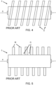
- Figure 4 shows a prior art spiral microfibre brushbar;
- Figure 5 shows a cross-sectional view of spiral microfibre brushbar of figure 4;
- Figure 6 shows a cross-sectional view of one half of a brushbar according to an embodiment of the invention;
- Figure 7 shows a cross-sectional view of one half of a brushbar according to an embodiment of the invention;
- Figure 8 shows a dual-spiral configuration of embodiments of the invention wherein one or more microfibre portions have been omitted for clarity;
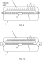
- Figure 9 shows a plan cross-sectional view of a wet and dry vacuum cleaner foot comprising a prior art brushbar, illustrating air leakage and side suction;
- Figure 10 shows a plan cross-sectional view of a wet and dry vacuum cleaner foot comprising a brushbar according to the invention, illustrating reduced air leakage and thus improved side suction;
- Figure 11 shows a cross-sectional view of one half of a brushbar according to an embodiment of the invention, comprising a transitional material between portions;
- Figure 12 shows a cross-sectional view of one half of a brushbar according to an embodiment of the invention, comprising three portions;
- Figure 13 shows a cross-sectional view of one half of a brushbar according to an embodiment of the invention, comprising a space between portions;
- Figure 14 shows a cross-sectional view of one half of a brushbar according to an embodiment of the invention, comprising three portions that are not arranged in order of the length of the microfibres in each portion;
- Figure 15 shows a cross-sectional view of one half of a brushbar according to an embodiment of the invention, comprising three portions that are not arranged in order of the length of the microfibres in each portion, and a space between portions;
- Figure 16 shows a cross-sectional view of one half of a brushbar according to an embodiment of the invention, comprising three portions and a transitional material between portions;
- Figure 17 shows a cross-sectional view of one half of a brushbar according to an embodiment of the invention, comprising three portions, a transitional material between portions, and a space between portions;
- Figure 18 shows a cross-sectional view of one half of a brushbar according to an embodiment of the invention, comprising three portions and a transitional material between portions, wherein the portions are not arranged in order of the length of the microfibres in each portion;
- Figure 19 shows a cross-sectional view of one half of a brushbar according to an embodiment of the invention, comprising three portions and a transitional material between portions, and a space between portions, and wherein the portions are not arranged in order of the length of the microfibres in each portion.
DETAILED DESCRIPTOIN OF EMBODIMENTS
-
The invention is in the field of surface cleaning and relates to a brushbar and a vacuum cleaner comprising the brushbar, wherein the brushbar has two or more portions of microfibre material of similar but different average microfibre lengths, resulting in improved suction and cleaning compared to a spiral brushbar, and resulting in improved efficiency compared to a full brushbar.
-
Since the portions have microfibre material of similar but different lengths, air leakage is reduced which results in stronger suction, compared to the known spiral brushbar. This improves side suction, which has additional effects of concentrating any water pooling and reducing water leakage at the side of the vacuum cleaner where side suction may otherwise not be sufficient.
-
Since the portions have microfibre material of similar but different lengths, the portions may selectively engage with the surface. Accordingly, in some scenarios, only one or only a proportion, i.e., not all, of the portions engage with the surface, thereby improving power efficiency compared to the full brushbar. In other scenarios, such as where significant debris is encountered or where the floor is uneven, further portions may engage with the surface to be cleaned resulting in improved cleaning compared to the known spiral brushbar (which comprises gaps between the spirals that prevents the brushbar contacting the floor where gaps are present).
-
Figure 1 illustrates a basic configuration of a wet and dry vacuum cleaner comprising a brushbar. The vacuum cleaner 1 comprises a microcontroller (uc) 2 and a foot 3 that comprises a motor 4 and brushbar 5. The motor 4 drives the brushbar 5, responsive to a signal from the uc 2. Other known elements of the vacuum cleaner such as a water collection reservoir, handle and on-off switch, which will be well understood by the skilled person, have been omitted.
-
Figure 2 shows a side view of a prior art full microfibre brushbar 5. The brushbar 5 spins around axis A, and comprises microfibre material M across its full width. The microfibre material M is of substantially uniform length along the length of the brushbar, thus the microfibre material M typically all contacts the floor as the brushbar 5 spins.
-
References to the "length" of the brushbar herein refers to the longest dimension of the brushbar, but it will be understood that in an operational orientation this direction may be considered by a user to be a "width" of the brushbar 5. For consistency, this longest dimension shall herein be referred to as the length of the brushbar.
-
Figure 3 shows a cross-sectional view of the full microfibre brushbar 5 of figure 2. The brushbar 5 comprises a roller 5 which is held in position by lugs L which engage with portions of the foot and which allow a rotational force to be applied to the brushbar 5 from the motor.
-
Figure 4 shows a prior art spiral microfibre brushbar. Again, the brushbar 5 rotates around an axis A, and comprises spirals S of microfibre material wrapped along the length of the brushbar. Gaps are present between the spirals. Sometimes, a much shorter material may be found between the spirals, as an incidental feature of manufacturing, and such material is undesirable as it increases weight whilst being too short to contact the surface (thus serving no useful purpose).
-
Figure 5 shows a cross-sectional view of spiral microfibre brushbar of figure 4. Along the length of the brushbar, portions of microfibre material M corresponding to adjacent spirals can be seen, spaced apart from other portions by gaps G.
-
Figure 6 shows a cross-sectional view of one half of a brushbar according to an embodiment of the invention. The brushbar comprises two spiral-wrapped adjacent portions P1, P2. The average length of the microfibre material in portion P2 is similar but different to that in portion P1. A ratio between the average lengths of microfibre in each portion can be defined. In the embodiment shown, the ratio of average length in P2 is approximately 80% that of average length in P1. However, the ratio may vary between 60% and 95% in embodiments. In embodiments, the length of microfibre material in any portion is substantially identical across the portions; in other words, the variation in the length of microfibre material within a portion may be substantially zero or tend towards zero.
-
The widths of the portions may be substantially the same, but in embodiments the width of the portions may be different to each other.
-
Figure 7 shows a cross-sectional view of one half of a brushbar according to an embodiment of the invention. Gaps G may be present between one or more portions. Optionally, the gaps G may be present between each portion. The width of the gaps may match the width of the portions, or may be different. The gaps may be substantially smaller than the width of the portions, to facilitate manufacture whilst maintaining the various benefits of the invention as set out herein.
-
Figure 8 shows a dual-spiral configuration of embodiments of the invention wherein one or more microfibre portions have been omitted for clarity. Here, a first spiral S1 and a second spiral S2, both relating to a portion of microfibre material of a particular length, are wrapped in opposite directions to meet it the middle or towards the middle of the brushbar. Due to the opposing directions of the spiral, dirt and debris may be directed towards the middle of the brushbar as the brushbar spins in a particular direction. One or more other pairs of spirals wrapped in opposite directions, corresponding to another portion of microfibre material of a different length, are also present, but are not shown.
-
Figures 9 and 10 show comparison cross-sectional plan views of a wet and dry vacuum cleaner comprising a prior art brushbar and a vacuum cleaner comprising a brushbar according to the invention. Both figures depict a vacuum cleaner foot 3 comprising a brushbar 5, and illustrating air leakage AL and side suction SU. A central suction opening SO is present, along with a strip 6 positioned adjacent to the brushbar 5 to generate side suction SU towards the suction opening SO.
-
In the embodiment with the prior art spiral brushbar, due to significant air leakage AL through gaps between the spirals of the brushbar, shown in Fig. 9, side suction SU is limited. In the embodiment comprising a brushbar according to the invention, shown in Fig. 10, the similar lengths of the microfibre material in the one or more portions reduces air leakage AL, and thus side suction SU is improved, resulting in aforementioned advantages.
-
Figure 11 shows a cross-sectional view of one half of a brushbar according to an embodiment of the invention, comprising a transitional material between portions. The transitional material T is positioned between adjacent portions and may make manufacture easier, since it prevents the need to have a sharp transition between microfibre length which can be difficult to achieve. The transitional material T may be nylon, or alternatively various other non-microfibre materials may be used.
-
Figure 12 shows a cross-sectional view of one half of a brushbar according to an embodiment of the invention, comprising three portions P1, P2, P3 which are spiral wrapped around the brushbar. The height of the microfibre material is different between the portions, and the relative height of the material in each portion is 60-95% of the height of the next longest brushbar; that is, the length of the material in portion P3 is between 60 and 95% of the material length in portion P2, and the length of the material in portion P2 is between 60 and 95% of the material length in portion P1. The embodiment herein describes three embodiments, but any number N of portions may be present.
-
Figure 13 shows a cross-sectional view of one half of a brushbar according to an embodiment of the invention, comprising a space between portions. The embodiment comprises the same features and a variations as the embodiment of figure 12, except that additionally a gap G may be present between one or more of the portions. Optionally, the gaps G may be present between each portion. The width of the gaps may match the width of the portions, or may be different. The gaps may be substantially smaller than the width of the portions, to facilitate manufacture whilst maintaining the various benefits of the invention as set out herein.
-
Figure 14 shows a cross-sectional view of one half of a brushbar according to an embodiment of the invention, comprising three portions that are not arranged in order of the length of the microfibres in each portion. The features and variations found as described in relation to figure 12 are equally applicable, except that in this embodiment the portions are not in height order. Portion P1 may contain the longest microfibre material, portion P2 may contain the next longest microfibre material, and portion P3 may contain the next longest (i.e. the shortest) microfibre material. In this embodiment, the portions are not arranged in height order, so portion P3 with the shortest material is positioned between the portion P1 with the longest material and portion P2 with the second-longest material. The relative heights of the material in the portions is variable as herein discussed in relation to other embodiments.
-
Figure 15 shows a cross-sectional view of one half of a brushbar according to an embodiment of the invention, comprising three portions that are not arranged in order of the length of the microfibres in each portion, and a space between portions. This embodiment is the same as the embodiment of figure 14, except that additionally a gap G may be present between one or more of the portions. Optionally, the gaps G may be present between each portion. The width of the gaps may match the width of the portions, or may be different. The gaps may be substantially smaller than the width of the portions, to facilitate manufacture whilst maintaining the various benefits of the invention as set out herein. The variations discussed in relation to the embodiment shown figure 14 apply equally to figure 15.
-
Figure 16 shows a cross-sectional view of one half of a brushbar according to an embodiment of the invention, comprising three portions and a transitional material between portions. This embodiment is the same as the embodiment of figure 14, except that a transitional material T is present between one or more adjacent portion. The variations discussed in relation to the embodiment shown in figure 14 apply equally to this embodiment.
-
Figure 17 shows a cross-sectional view of one half of a brushbar according to an embodiment of the invention, comprising three portions, a transitional material between portions, and a space between portions. This embodiment comprises the features of as discussed in relation to figure 16, but additionally introduces a gap G between one or more of the portions.
-
Figure 18 shows a cross-sectional view of one half of a brushbar according to an embodiment of the invention, comprising three portions and a transitional material between portions, wherein the portions are not arranged in order of the length of the microfibres in each portion. Thus, this embodiment combines the features of the embodiments shown in figure 14 (portions not ordered by height) and figure 16 (transitional material between portions).
-
Figure 19 shows a cross-sectional view of one half of a brushbar according to an embodiment of the invention, comprising three portions and a transitional material between portions, and a space between portions, and wherein the portions are not arranged in order of the length of the microfibres in each portion. This embodiment is the same as the embodiment discussed in relation to figure 18 except that a gap G is present between one or more of the microfibre portions.
-
In each disclosed embodiment of the invention, the microfibre portions may comprise microfibres each with a diameter in the range 6 to 20 microns. However, embodiments of the invention are not limited to microfibre diameters that fall within this range. The term diameter refers to the average (arithmetic mean) geometric diameter of the microfibre along its length.
-
It will be clear to a person skilled in the art that the scope of the invention is not limited to the examples discussed in the foregoing, but that several amendments and modifications thereof are possible without deviating from the scope of the invention as defined in the attached claims. It is intended that the invention be construed as including all such amendments and modifications insofar they come within the scope of the claims or the equivalents thereof. While the invention has been illustrated and described in detail in the figures and the description, such illustration and description are to be considered illustrative or exemplary only, and not restrictive. The invention is not limited to the disclosed embodiments. The drawings are schematic, wherein details that are not required for understanding the invention may have been omitted, and not necessarily to scale.
-
It will be clear to the skilled person that the embodiments described herein are exemplary and further embodiments may be contemplated. In particular, one or more features of any of the embodiments herein may be combined with the one or more features of one or more other embodiments, to create new embodiments, except only where such features are clearly incompatible.
-
Variations to the disclosed embodiments can be understood and effected by a person skilled in the art in practicing the claimed invention, from a study of the figures, the description and the attached claims. In the claims, the word "comprising" does not exclude other steps or elements, and the indefinite article "a" or "an" does not exclude a plurality. Any reference signs in the claims should not be construed as limiting the scope of the invention.
-
Elements and aspects discussed for or in relation with a particular embodiment may be suitably combined with elements and aspects of other embodiments, unless explicitly stated otherwise. Thus, the mere fact that certain measures are recited in mutually different dependent claims does not indicate that a combination of these measures cannot be used to advantage.
-
The terms "comprise" and "include" as used in this text will be understood by a person skilled in the art as covering the term "consist of". Hence, the term "comprise" or "include" may in respect of an embodiment mean "consist of", but may in another embodiment mean "contain/have/be equipped with at least the defined species and optionally one or more other species".
-
Notable aspects of the invention are summarized as follows. In the field of surface cleaning, a brushbar 5 is provided, comprising two or more microfibre portions each having microfibre material of an average length, of which portions at least one portion comprises an average length different to at least one other portion. The ratio of relative length between average lengths of the different portions, when the lengths are ordered in a set of unique lengths in length order, is 60-95%. In other embodiments, the ratio may be 65-90%. In other embodiments, the ratio may be 70 to 85%.