EP4470361A1 - Gate latch pocket deflector - Google Patents
Gate latch pocket deflector Download PDFInfo
- Publication number
- EP4470361A1 EP4470361A1 EP24172593.6A EP24172593A EP4470361A1 EP 4470361 A1 EP4470361 A1 EP 4470361A1 EP 24172593 A EP24172593 A EP 24172593A EP 4470361 A1 EP4470361 A1 EP 4470361A1
- Authority
- EP
- European Patent Office
- Prior art keywords
- latch
- gate
- housing
- coupled
- retainer
- Prior art date
- Legal status (The legal status is an assumption and is not a legal conclusion. Google has not performed a legal analysis and makes no representation as to the accuracy of the status listed.)
- Pending
Links
Images






Classifications
-
- A—HUMAN NECESSITIES
- A01—AGRICULTURE; FORESTRY; ANIMAL HUSBANDRY; HUNTING; TRAPPING; FISHING
- A01F—PROCESSING OF HARVESTED PRODUCE; HAY OR STRAW PRESSES; DEVICES FOR STORING AGRICULTURAL OR HORTICULTURAL PRODUCE
- A01F15/00—Baling presses for straw, hay or the like
- A01F15/08—Details
- A01F15/0875—Discharge devices
-
- A—HUMAN NECESSITIES
- A01—AGRICULTURE; FORESTRY; ANIMAL HUSBANDRY; HUNTING; TRAPPING; FISHING
- A01F—PROCESSING OF HARVESTED PRODUCE; HAY OR STRAW PRESSES; DEVICES FOR STORING AGRICULTURAL OR HORTICULTURAL PRODUCE
- A01F15/00—Baling presses for straw, hay or the like
- A01F15/07—Rotobalers, i.e. machines for forming cylindrical bales by winding and pressing
-
- A—HUMAN NECESSITIES
- A01—AGRICULTURE; FORESTRY; ANIMAL HUSBANDRY; HUNTING; TRAPPING; FISHING
- A01F—PROCESSING OF HARVESTED PRODUCE; HAY OR STRAW PRESSES; DEVICES FOR STORING AGRICULTURAL OR HORTICULTURAL PRODUCE
- A01F15/00—Baling presses for straw, hay or the like
- A01F15/08—Details
-
- A—HUMAN NECESSITIES
- A01—AGRICULTURE; FORESTRY; ANIMAL HUSBANDRY; HUNTING; TRAPPING; FISHING
- A01F—PROCESSING OF HARVESTED PRODUCE; HAY OR STRAW PRESSES; DEVICES FOR STORING AGRICULTURAL OR HORTICULTURAL PRODUCE
- A01F15/00—Baling presses for straw, hay or the like
- A01F15/08—Details
- A01F15/0875—Discharge devices
- A01F15/0883—Discharge devices for round balers
-
- A—HUMAN NECESSITIES
- A01—AGRICULTURE; FORESTRY; ANIMAL HUSBANDRY; HUNTING; TRAPPING; FISHING
- A01F—PROCESSING OF HARVESTED PRODUCE; HAY OR STRAW PRESSES; DEVICES FOR STORING AGRICULTURAL OR HORTICULTURAL PRODUCE
- A01F15/00—Baling presses for straw, hay or the like
- A01F15/07—Rotobalers, i.e. machines for forming cylindrical bales by winding and pressing
- A01F2015/0785—Latching or locking means for the tailgate of the rotobaler
Definitions
- the present disclosure relates generally to a baler implement, especially a round baler having a gate to release a bale.
- balers including round balers, roll the crop material in a spiral fashion into a bale in a baling chamber.
- the balers may have a main housing and a gate to form the bailing chamber and the gate may pivot relative to the main housing to release the bale.
- a baler implement may include a main frame, a main housing, a gate, a latch housing, a latch, and a debris shield.
- the main frame extends along a central longitudinal axis between a forward end and a rearward end relative to a direction of travel.
- the main housing is attached to and supported by the main frame.
- the gate is positioned adjacent the rearward end of the main frame and attached to and rotatably supported by the main housing.
- the gate is pivotably moveable about a gate axis that is perpendicular to the central longitudinal axis of the main frame.
- the latch housing is coupled to one of the main frame and the gate.
- the latch housing has a retainer and defines a pocket having an opening.
- the latch is coupled to an other of the main frame and the gate for engaging the retainer of the latch housing.
- the latch is controllable between a release position operable to disengage the retainer to allow the gate to move relative to the main housing and an engaged position operable to engage the retainer to hold the gate relative to the main housing.
- the debris shield is positioned to at least partially cover the opening. The debris shield is resiliently deformable to allow the latch to move through the opening of the pocket to limit debris entering the pocket.
- a latch assembly coupled to a main frame of a baler implement, in particular a baler implement according to at least on of the claims 1 to 13 or 15, to selectively hold a gate relative to a main housing of the baler implement.
- the latch assembly may include a latch housing, a latch, and a debris shield.
- the latch housing is coupled to one of the main frame and the gate.
- the latch housing has a retainer and defines a pocket having an opening.
- the latch is coupled to an other of the main frame and the gate for engaging the retainer of the latch housing.
- the latch is controllable between a release position operable to disengage the retainer to allow the gate to move relative to the main housing and an engaged position operable to engage the retainer to hold the gate relative to the main housing.
- the debris shield is positioned to at least partially cover the opening. The debris shield is resiliently deformable to allow the latch to move through the opening of the pocket to limit debris entering the pocket.
- a baler implement may include a main frame, a main housing, a gate, a latch housing, a latch, and a debris shield.
- the main frame extends along a central longitudinal axis between a forward end and a rearward end relative to a direction of travel.
- the main housing is attached to and supported by the main frame.
- the gate is positioned adjacent the rearward end of the main frame and attached to and rotatably supported by the main housing.
- the gate is pivotably moveable about a gate axis that is perpendicular to the central longitudinal axis of the main frame.
- the latch housing is coupled to one of the main house and the gate.
- the latch housing has a retainer and defines a pocket having an opening.
- the latch is coupled to an other of the main house and the gate for engaging the retainer of the latch housing.
- the latch is controllable between a release position operable to disengage the retainer to allow the gate to move relative to the main housing and an engaged position operable to engage the retainer to hold the gate relative to the main housing.
- the debris shield is positioned to at least partially cover the opening. The debris shield is resiliently deformable to allow the latch to move through the opening of the pocket to limit debris entering the pocket.
- a gate For some bales, such as a round baler, a gate should be securely closed during bale formation to ensure baling performance and avoid crop material leaving a baling chamber defined by a main housing and the gate.
- a latch may be equipped to hold the gate closed during bale formation. The latch can unlock the gate to release the bale.
- the latch is moveable in a pocket formed by a latch housing.
- debris such as crop material, may build up in the pocket, thereby affecting the operation of the latch. The gate therefore may not be securely closed.
- the baler implement 20 in this implementation is a round baler with a variable baling chamber; in another implementation, the baler implement 20 can be a round baler with a fixed baling chamber.
- the baler implement 20 includes a main frame 22.
- the main frame 22 extends along a central longitudinal axis 226 between a forward end 222 and a rearward end 224 relative to a direction of travel.
- One or more ground engaging elements 24, such as but not limited to one or more wheels and/or tracks, are attached to and rotatably supported by the main frame 22.
- a tongue 21 may be coupled to the main frame 22 at the forward end 222 of the main frame 22.
- a hitch arrangement 212 may be included with the tongue 21.
- the hitch arrangement 212 may be used to attach the baler implement 20 to a traction unit (not shown), such as but not limited to an agricultural tractor.
- the baler implement 20 may be self-propelled, in which case the traction unit and the baler implement 20 are configured as a single, self-propelled vehicle.
- the baler implement 20 includes a pick-up 26 disposed proximate the forward end 222 of the main frame 22.
- the pick-up 26 gathers crop material from a ground surface and directs the gathered crop material toward and into an inlet 34 of the baling chamber 32.
- the pick-up 26 moves crop material along a crop path 92 relative to the main frame 22.
- the pick-up 26 may include, but is not limited to tines, forks, augers, conveyors, baffles, etc., for gathering and moving the crop material.
- the baler implement 20 includes a baling system 30 having a main housing 31 forming a baling chamber 32.
- the main housing 31 is attached to and supported by the main frame 22.
- the main housing 31 may include one or more walls or panels that at least partially enclose and/or define the baling chamber 32.
- the baler implement 20 further includes a gate 36, which may define the baling chamber 32 with the main housing 31.
- the gate 36 is attached to and rotatably supported by the main housing 31.
- the gate 36 is positioned adjacent the rearward end 224 of the main frame 22 and is pivotably moveable about a gate axis 362.
- the gate axis 362 is generally horizontal and perpendicular to the central longitudinal axis 226 of the main frame 22.
- the gate 36 is moveable between a closed position for forming a bale 90 within the baling chamber 32, and an open position for discharging the bale 90 from the baling chamber 32. As shown in FIGS. 3 and 4 , one side of the gate 36 is shown.
- the gate 36 may have a first beam 364 and a second beam 366 amounted on a side panel 367 of the gate 36.
- the second beam 366 is positioned below the first beam 364.
- Other elements, such as actuators 40 may be coupled to the first beam 364 so as to pivot the gate 36.
- the baler implement 20 may also include a latch assembly 50 controllable between a release position to release the gate 36 and an engaged position to lock the gate 36. The movement of the gate 36 is described in greater detail below.
- the baler implement 20 may be configured as a variable chamber baler, or as a fixed chamber baler.
- the baler implement 20 shown in the FIGS. 1 and 2 and described herein is depicted and described as a variable chamber baler.
- the variable chamber baler includes a plurality of longitudinally extending side-by-side forming belts 37 that are supported by a plurality of rollers 38.
- the bale 90 is formed by the forming belts 37 and one or more side walls of the main housing 31.
- the crop material is directed through the inlet 34 and into the baling chamber 32, whereby the forming belts 37 roll the crop material in a spiral fashion into the bale 90 having a cylindrical shape.
- the forming belts 37 apply a constant pressure to the crop material as the crop material is formed into the bale 90.
- a belt tensioner 39 continuously moves the forming belts 37 radially outward relative to a center of the cylindrical bale 90 as the diameter of the bale 90 increases.
- the belt tensioner 39 maintains the appropriate tension in the forming belts 37 to obtain the desired density of the crop material.
- the baler implement 20 includes a wrap system 80.
- the wrap system 80 is operable to wrap the bale 90 with a wrap material inside the baling chamber 32. Once the bale 90 is formed to a desired size, the wrap system 80 feeds the wrap material into the baling chamber 32 to wrap the bale 90 and thereby secure the crop material in a tight package and maintain the desired shape of the bale 90.
- the wrap material may include, but is not limited to, a twine, a net mesh, or a solid plastic wrap. Movement of the gate 36 into the open position simultaneously moves the belts clear of the formed bale 90 and allows the formed and wrapped bale to be discharged through the rear of the baling chamber 32.
- the baler implement 20 may include the two actuators 40 coupled to the gate 36 and operable to pivot the gate 36 upward to open the gate 36 and to pivot the gate downward to close the gate 36.
- the actuator 40 in the present disclosure may be a hydraulic cylinder to pivot the gate 36.
- the actuator 40 may be an electric linear actuator or other types of actuators.
- the actuator 40 may include a rod 42 and a cap 44. The rod 42 extends relative to the cap 44 to open the gate 36 (as shown in FIG. 4 ) and retracts relative to the cap 44 to close the gate 36 (as shown in FIG. 3 ).
- the rod 42 has a rod end 422 coupled to the first beam 364 via a connector 365 mounted on the first beam 364 or the side panel 367.
- the cap end 442 coupled to the main frame 22 via the latch assembly 50 that is mounted on the main frame 22.
- the cap end 442 of the actuator 40 may be coupled to another portion of the main frame 22 to support the weight of the gate 36 when the actuator 40 extends to pivot the gate 36.
- the latch assembly 50 may include a latch housing 52 and a latch 54 selectively engages the latch housing 52.
- the latch housing 52 may be coupled to one of the main frame 22 and the gate 36; the latch 54 may be coupled to the other one of the main frame 22 and the gate 36.
- the latch housing 52 is mounted on the main frame 22 and the latch 54 is coupled to the gate 36.
- the latch housing 52 may be coupled to the gate 36 and the latch 54 may be coupled to the main frame 22 (not shown).
- the latch housing 52 may be coupled to one of the main housing 31 and the gate 36; the latch may be coupled to the other one of the main housing 31 and the gate 36 (not shown).
- a debris shield 60 (shown in FIGS.7A-9 ) of the latch assembly 50 is omitted for showing the structure of the latch housing 52.
- the latch housing 52 may define a pocket 522 having opening.
- the latch housing 52 may have a retainer 524, a first portion 526, and a second portion 528.
- the first portion 526 and the second portion 528 are plates (first plate and second plate) parallel to each other, and the retainer 524 is positioned between the first portion 526 and the second portion 528.
- the retainer 524 may be a block, coupled between the first portion 526 and the second portion 528 through welding, fasteners, or other means.
- the latch housing 52 may also include a pin 527 or other type of structure that is coupled between the first portion 526 and the second portion 528.
- the retainer 524 and the pin 527 connect the first portion 526 and the second portion 528 and enhance the strength of the structure of the latch housing 52.
- the main frame 22 may include a support beam 225 coupled between the main housing 31 and an axle 242 (shown in FIG. 3 ) of the ground engaging elements 24.
- the lower edge of the first portion 526 of the latch housing 52 may be coupled to the top surface of the support beam 225 via welding or other means.
- the second portion 528 of the latch housing 52 may be coupled to the main housing 31 or the support beam 225.
- the actuator 40 includes a lower end (i.e., the cap end 442) positioned between and supported by the first portion 526 and second portion 528 of the latch housing 52.
- a fastener 443 is positioned through the first portion 526, the cap end 442 of the actuator 40, and the second portion 528.
- the latch 54 is pivotably coupled to the second beam 366 of the gate 36, around a pivot point 542, for engaging the retainer 524 of the latch housing 52.
- the latch 54 is controllable between a release position ( FIG. 6B ) operable to disengage the retainer 524 to allow the gate 36 to move relative to the main housing 31 and an engaged position ( FIG. 6A ) operable to engage the retainer 524 to hold the gate 36 relative to the main housing 31.
- the latch 54 may be a hook shape with a flat surface contacting a tilted surface of the retainer 524.
- the pivotal movement of the latch 54 may be driven by the actuator 40 which also pivots the gate 36 as shown in FGIS. 3, 4, 6A, 6B, or driven by another individual actuator (not shown) unrelated to pivoting the gate 36.
- the latch assembly 50 may include a linkage 55 coupled to the latch 54 and a latch rod 56, a lower end of which is coupled to the linkage 55 to pivot the latch 54.
- the lower end (i.e., a second end) of the latch rod 56 may directly be coupled to the latch 54 for pivoting.
- the connector 365 mounted on the first beam 364 or the side panel 367 (not shown) has a slot 3652 with an upper end 3653 and a lower end 3654.
- the rod end 422 of the actuator 40 is coupled to a pin 3655, which is slidable between the upper end 3653 and the lower end 3654 of the slot 3652.
- latch rod 56 An upper end (i.e., a first end) of latch rod 56 is coupled to the rod end 422 of the actuator 40 via the pin 3655 in the connector 365.
- the pin 3655 moved by the rod end 422 of actuator 40, slides from the lower end 3654 to the upper end 3653 of the slot 3652.
- the latch rod 56 is lifted upward to pivot the latch 54 clockwise, and the latch 54 pivots from the engaged position ( FIG. 6A ) to the release position ( FIG. 6B ). Meanwhile, the gate 36 remains at the closed position.
- the gate 36 starts to open until the open position to release the bale 90.
- the actuator 40 retracts, the gate 36 pivots from the open position to the closed position, with the pin 3655 remains at the upper end 3653 of the slot 3652 until the gate 36 is closed at the closed position.
- the actuator 40 continues to retract, and the pin 3655 starts to slide from the upper end 3653 to the lower end 3654.
- the latch rod 56 is pushed downward to pivot the latch 54 counterclockwise.
- the latch 54 pivots from the release position ( FIG. 6B ) to the engaged position ( FIG. 6A ) to hold the gate 36 closed.
- the latch rod 56 may further include a sliding arm 58 slidably position at or near the lower end of the latch rod 56.
- the latch rod 56 may include an upper stop 562, lower stop 564, and a spring 566.
- the lower end of the spring 566 abuts the base 582 (top) of the sliding arm 58.
- the spring 566 and the base 582 of the sliding arm 58 are positioned between the upper stop 562 and the lower stop 564.
- the sliding arm 58 extends downward from the base 582, passes over the lower stop 564, and is connected to the linkage 55.
- the actuator 40 extends and the lower stop 564, which is a nut in this implementation, pulls up the base 582 of the sliding arm 58 without substantially changing the length of the spring 566.
- the sliding arm 58 pulls the linkage 55 to unlock the latch 54.
- the actuator 40 retracts and pushes the latch rod 56 downward.
- the spring 566 the top of which is abutted by the upper stop 562, is operable to push the base 582 of sliding arm 58 downward to pivot the latch 54 counterclockwise. When there is no debris in the pocket 522, the spring 566 may be slightly compressed to pivot the latch 54.
- the spring 566 may be compressed more to provide sufficient down force to pivot the latch 54 to pass through the debris in the pocket 522.
- the spring 566 provides compliance in the event that the latch 54 is held up due to the debris interfering the pivotal movement of the latch 54 or even clogged in the pocket 522.
- the spring 566 and the sliding arm 58 prevent the down force from the actuator 40 damaging the structure of latch assembly 50.
- the spring 566 and the sliding arm 58 may be replaced by telescoping features or other sliding features. It is noted that the when the pocket 522 is clogged by the debris, the latch 54 may not pivot to engage the retainer 524. As such, the latch 54 cannot be moved to the engaged position (as shown in FIG. 6A ) and the gate 36 may not close completely.
- the latch assembly 50 may include a debris shield 60 positioned to at least partially cover the opening of the pocket 522.
- the debris shield 60 may be positioned between the lower end (i.e., cap end 442) of the actuator 40 and the retainer 524 in a direction parallel to the central longitudinal axis.
- the debris shield 60 may be positioned between the first portion 526 and the second portion 528 of the latch housing 52, which may be parallel to each other.
- the debris shield 60 is resiliently deformable to allow the latch 54 to move through the opening of the pocket 522 ( FIG. 5 ) to limit debris entering the pocket 522.
- the debris shield 60 prevents excessive buildup which prevents the lock assembly 50(lock mechanism) from fully engaging.
- the materials of the debris shield 60 may vary, and may include but are not limited to, a brush(es), a flap(s), a foam(s), or other materials that are resiliently deformable.
- the debris shield 60 may prevent the debris from entering the pocket 522; however, in some implementation, because the pocket 522 can tolerate some smaller debris which can eventually pass through the pocket 522, the debris shield 60 may not completely block all the debris entering the pocket 522.
- the debris shield 60 may include at least one brush positioned across the opening of the pocket 522. As shown in FIG. 7A , the debris shield 60 includes a first brush 602 having a first brush base 6022 couple to the first portion 526 of the latch housing 52 and first bristles 6024 extending from the first brush base 6022 toward the second portion 528 of the latch housing 52. The latch 54 is omitted from FIG. 7A . The first bristles 6024 may extend toward the second portion 528 to reach the second portion 528 or even pass the second portion 528. The first brush base 6022 may be mounted on the top edge of the first portion 526.
- the front portion of the first brush base 6022 may be higher than the rear portion of the first brush base 6022, and the first bristles 6024, aligned along the top edge of the first brush base 6022, form an inclined surface.
- the debris may roll on the included surface formed by the first bristles 6024 to leave the pocket 522 of the latch housing 52.
- FIG. 7B illustrates the latch 54 moving through the first bristles 6024 of the first brush 602, which are resiliently deformable materials. The portion of the first bristles 6024 other than those deformed by the latch 54 remain their original positions to at least partially cover the opening of the pocket 522.
- the debris shield 60 includes the first brush 602 having the first brush base 6022 couple to the first portion 526 of the latch housing 52 and the first bristles 6024 extending from the first brush base 6022 toward the second portion 528.
- the debris shield 60 also includes a second brush 604 having a second brush base 6042 coupled to the second portion 528 of the latch housing 52 and second bristles 6044 extending from the second brush base 6042 toward the first portion 526.
- the second brush base 6042 may be mounted on the top edge of the second portion 528.
- the front portion of the second brush base 6042 may be higher than the rear portion of the second brush base 6042, and the second bristles 6044, aligned along the top edge of the second brush base 6042, forms half of an inclined surface.
- the first bristles 6024 in this implementation, may be shorter than the first bristles 6024 in the implementation shown in FIG. 7A and form the other half of the inclined surface.
- the distal ends of the first bristles 6024 and the distal ends of the second bristles 6044 face each other with small gap along the path of the latch 54 travels. In another implementation (not shown), the first bristles 6024 and the second bristles 6044 may overlap along the direction of their extensions.
- first brush base 6022 and/or the second brush base 6042 providing the inclined surface of the first bristles 6024 and/or the second bristles are explanatory.
- the first brush base 6022 and the second brush base 6042 may be another structure or material, such as glue that attaches the first bristles 6024 to the first portion 526 and/or the second bristles 6044 to the second portion 528.
- the debris shield 60 includes the first brush 602 having the first brush base 6022 coupled to the first portion 526 of the latch housing 52 and the second brush base 6042 coupled to the second portion 528 of the latch housing 52, a brush base 6032 coupled between the first brush base 6022 and the second brush base 6042 (or between the first portion 526 and the second portion 528), and first bristles 6024 extending from the brush base 6032 toward the retainer 524.
- the front portion of the first brush base 6022 may be higher than the rear portion of the first brush base 6022
- the front portion of the second brush base 6042 may be higher than the rear portion of the second brush base 6042
- the first bristles 6024 extend from the brush base 6032 and go down longitudinally to form an inclined surface.
- there is no first brush base 6022 and second brush base 6042 and the brush base 6032 is coupled between the first portion 526 and the second portion 528 of the latch housing 52 with the first bristles 6024 extending toward the retainer 524.
- the debris shield 60 may include at least one flexible flap coupled to one of the first portion 526 and the second portion 528 of the latch housing 52 and extending toward the other one of the first portion 526 and the second portion 528 of the latch housing 52.
- the at least one flexible flap includes a first flexible flap 606 and the second flexible flap 608.
- the first flexible flap 606 is coupled to the first portion 526 via the first flap base 6062 and extends toward the second portion 528 of the latch housing 52 to form a distal edge 6064.
- the second flexible flap 608 is coupled to the second portion 528 of the latch housing 52 via the second flap base 6082 and extends toward the first portion 526 with a distal edge 6084 of the second flexible flap 608 facing the distal edge 6064 of the first flexible flap 606.
- the latch 54 may be moveable between the distal edge 6064 of the first flexible flap 606 and the distal edge 6084 of the second flexible flap 608 during a transition between the engaged position and the release position.
- the distal edge 6064 of the first flexible flap 606 has a first notch 6065 and the distal edge 6084 of the second flexible flap 608 has a second notch 6085 corresponding to the first notch 6065.
- the at least one flexible flap may include a single flexible flap 609 coupled to one of the first portion 526 and the second portion 528 of the latch housing 52 and extending to the other one of the first portion 526 and the second portion 528 of the latch housing 52.
- the flexible flap 609 may include a hole 6095. Like the first notch 6065 and the second notch 6085 shown in FIG. 8A , the hole 6095 may receive the latch 54 when the latch 54 is in the engaged position.
- the flexible flap 609 may include a slit 6096 connected to the hole 6095.
- the latch 54 may pass through the hole 6095 and the slit 6096 during the transition between the engaged position and the release position.
- the hole 6095 and the slit 6096 shown in FIG. 8B are merely example.
- the hole 6095 has a wider width than the slit 6096.
- the hole 6095 and the slit 6096 may be replaced by a longer slit (not shown).
- the material of the flexible flap is deformable for the latch 54 passing through during the transition between the engaged and disengaged positions.
- the debris shield includes at least one foam block.
- the foam block may include and be manufactured from a foam material that is a deformable material.
- the foam block may be coupled to one of the first portion 526 and the second portion 528 and extend toward the other one of the first portion 526 and the second portion 528.
- the at least one foam block includes a first foam block 610 and a second foam block 612.
- the first foam block 610 is coupled to the first portion 526 via a first foam base 6102 and extends toward the second portion 528 of the latch housing 52 to form a distal edge 6104.
- the second foam block 612 is coupled to the second portion 528 of the latch housing 52 via a second foam base 6122 and extends toward the first portion 526 with a distal edge 6124 of the second foam block 612 facing the distal edge 6104 of the first foam block 610.
- the latch 54 may moveable between the distal edge 6104 of the first foam block 610 and the distal edge 6124 of the second foam block 612 during a transition between the engaged position and the release position.
- the first foam block 610 has a ramp 6106 near the distal edge 6104 and the second foam block 612 has a ramp 6126 near the distal edge 6124 corresponding to the ramp 6106.
- the at least one foam block may include a single foam coupled to one of the first portion 526 and the second portion 528 of the latch housing 52 and extending to the other one of the first portion 526 and the second portion 528 of the latch housing 52. The material of the foam is deformable for the latch 54 passing through during the transition between the engaged and disengaged positions.
- the ramps 6106, 6126 are configured to decrease the likelihood of the latch 54 snagged by the first foam block 610 and the second foam block during the transition between the engaged position and the release position.
- structures such as chamfers and rolled edges may be near the distal edges 6104, 6124.
- there may be a gap between distal edges 6104, 6124 that is greater than the thickness of the latch 54 to allow the latch 54 to move smoothly during the transition.
- a technical effect of one or more of the example embodiments disclosed herein is to provide a debris shield positioned to at least partially cover an opening of a pocket of a latch housing without debris clogged therein, so as to allow the latch to engage or release from the retainer.
- Another technical effect of one or more of the example embodiments disclosed herein is to protect the latch assembly driven by the actuator to lock the gate from damage due to the debris clogged in the latch housing.
- At least one of A, B, and C indicates the possibilities of only A, only B, only C, or any combination of two or more of A, B, and C (e.g., A and B; B and C; A and C; or A, B, and C).
Landscapes
- Life Sciences & Earth Sciences (AREA)
- Environmental Sciences (AREA)
- Specific Sealing Or Ventilating Devices For Doors And Windows (AREA)
Abstract
A baler implement (20) may include a main frame (22), a main housing (31), a gate (36), a latch housing (52), a latch (54), and a debris shield (60). The main housing (31) is supported by the main frame (22). The gate (36) is attached to and rotatably supported by the main housing (31). The latch housing (52) is coupled to one of the main frame (22) and the gate (36). The latch housing (52) has a retainer (524) and defines a pocket (522). The latch (54) is coupled to an other of the main frame (22) and the gate (36). The latch (54) is controllable between a release position operable to disengage the retainer (524) to allow the gate (36) to move relative to the main housing (31) and an engaged position operable to engage the retainer (524) to hold the gate (36) relative to the main housing (31). The debris shield (60) is resiliently deformable to allow the latch (54) to move through the opening of the pocket (522) to limit debris entering the pocket (522).
Description
- The present disclosure relates generally to a baler implement, especially a round baler having a gate to release a bale.
- Some balers, including round balers, roll the crop material in a spiral fashion into a bale in a baling chamber. The balers may have a main housing and a gate to form the bailing chamber and the gate may pivot relative to the main housing to release the bale.
- According to an aspect of the present disclosure, a baler implement may include a main frame, a main housing, a gate, a latch housing, a latch, and a debris shield. The main frame extends along a central longitudinal axis between a forward end and a rearward end relative to a direction of travel. The main housing is attached to and supported by the main frame. The gate is positioned adjacent the rearward end of the main frame and attached to and rotatably supported by the main housing. The gate is pivotably moveable about a gate axis that is perpendicular to the central longitudinal axis of the main frame. The latch housing is coupled to one of the main frame and the gate. The latch housing has a retainer and defines a pocket having an opening. The latch is coupled to an other of the main frame and the gate for engaging the retainer of the latch housing. The latch is controllable between a release position operable to disengage the retainer to allow the gate to move relative to the main housing and an engaged position operable to engage the retainer to hold the gate relative to the main housing. The debris shield is positioned to at least partially cover the opening. The debris shield is resiliently deformable to allow the latch to move through the opening of the pocket to limit debris entering the pocket.
- According to an aspect of the present disclosure, a latch assembly coupled to a main frame of a baler implement, in particular a baler implement according to at least on of the claims 1 to 13 or 15, to selectively hold a gate relative to a main housing of the baler implement is introduced. The latch assembly may include a latch housing, a latch, and a debris shield. The latch housing is coupled to one of the main frame and the gate. The latch housing has a retainer and defines a pocket having an opening. The latch is coupled to an other of the main frame and the gate for engaging the retainer of the latch housing. The latch is controllable between a release position operable to disengage the retainer to allow the gate to move relative to the main housing and an engaged position operable to engage the retainer to hold the gate relative to the main housing. The debris shield is positioned to at least partially cover the opening. The debris shield is resiliently deformable to allow the latch to move through the opening of the pocket to limit debris entering the pocket.
- According to an aspect of the present disclosure, a baler implement may include a main frame, a main housing, a gate, a latch housing, a latch, and a debris shield. The main frame extends along a central longitudinal axis between a forward end and a rearward end relative to a direction of travel. The main housing is attached to and supported by the main frame. The gate is positioned adjacent the rearward end of the main frame and attached to and rotatably supported by the main housing. The gate is pivotably moveable about a gate axis that is perpendicular to the central longitudinal axis of the main frame. The latch housing is coupled to one of the main house and the gate. The latch housing has a retainer and defines a pocket having an opening. The latch is coupled to an other of the main house and the gate for engaging the retainer of the latch housing. The latch is controllable between a release position operable to disengage the retainer to allow the gate to move relative to the main housing and an engaged position operable to engage the retainer to hold the gate relative to the main housing. The debris shield is positioned to at least partially cover the opening. The debris shield is resiliently deformable to allow the latch to move through the opening of the pocket to limit debris entering the pocket.
- Other features and aspects will become apparent by consideration of the detailed description, claims, and accompanying drawings.
- The detailed description of the drawings refers to the accompanying figures.
-
FIG. 1 is a schematic perspective view of a baler implement. -
FIG. 2 is a schematic side view of the baler implement ofFIG. 1 . -
FIG. 3 is perspective view of a main housing with an exterior panel omitted and a gate of the baler implement; the gate is at a closed position. -
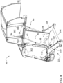
FIG. 4 is perspective view of the main housing with the exterior panel omitted and the gate of the baler implement; the gate is at an open position. -
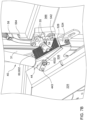
FIG. 5 is an enlarged perspective view of a latch assembly of the baler implement with a debris shield omitted for clarity. -
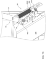
FIG. 6A is a side view of the latch assembly of the baler implement showing an engaged position of a latch with the debris shield and a first portion of a latch housing omitted for clarity. -
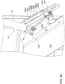
FIG. 6B is a side view of the latch assembly of the baler implement showing a release position of the latch with the debris shield and the first portion of the latch housing omitted for clarity. -
FIG. 7A illustrates an implementation of the debris shield having a first brush at least partially covering an opening of a pocket of the latch housing, with the latch omitted for clarity. -
FIG. 7B illustrates the implementation of the debris shield inFIG. 7A , with the latch passing through bristles of the first brush. -
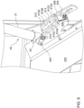
FIG. 7C illustrates an implementation of the debris shield having a first brush and a second brush cooperatively and at least partially covering the opening of the pocket of the latch housing (the first brush may be different from the one shown inFIG. 7A ). -
FIG. 7D illustrates an implementation of the debris shield having a first brush extending longitudinally between the first and second portions of the latch housing. -
FIG. 8A illustrates an implementation of the debris shield having a first flexible flap and a second flexible flap cooperatively and at least partially covering the opening of the pocket of the latch housing. -
FIG. 8B illustrates an implementation of the debris shield having a single flexible flap at least partially covering the opening of the pocket of the latch housing. -
FIG. 9 illustrates an implementation of the debris shield having a first foam block and a second foam block cooperatively and at least partially covering the opening of the pocket of the latch housing. - Like reference numerals are used to indicate like elements throughout the several figures.
- For some bales, such as a round baler, a gate should be securely closed during bale formation to ensure baling performance and avoid crop material leaving a baling chamber defined by a main housing and the gate. A latch may be equipped to hold the gate closed during bale formation. The latch can unlock the gate to release the bale. The latch is moveable in a pocket formed by a latch housing. However, during the repetitive motion of the gate opening and closing or other situation, debris, such as crop material, may build up in the pocket, thereby affecting the operation of the latch. The gate therefore may not be securely closed.
- Referring to
FIGS. 1 and2 , a baler implement 20 is generally shown. The baler implement 20 in this implementation is a round baler with a variable baling chamber; in another implementation, the baler implement 20 can be a round baler with a fixed baling chamber. The baler implement 20 includes amain frame 22. Themain frame 22 extends along a centrallongitudinal axis 226 between aforward end 222 and arearward end 224 relative to a direction of travel. One or moreground engaging elements 24, such as but not limited to one or more wheels and/or tracks, are attached to and rotatably supported by themain frame 22. Atongue 21 may be coupled to themain frame 22 at theforward end 222 of themain frame 22. Ahitch arrangement 212 may be included with thetongue 21. Thehitch arrangement 212 may be used to attach the baler implement 20 to a traction unit (not shown), such as but not limited to an agricultural tractor. In other embodiments, the baler implement 20 may be self-propelled, in which case the traction unit and the baler implement 20 are configured as a single, self-propelled vehicle. - The baler implement 20 includes a pick-
up 26 disposed proximate theforward end 222 of themain frame 22. The pick-up 26 gathers crop material from a ground surface and directs the gathered crop material toward and into aninlet 34 of the baling chamber 32. The pick-up 26 moves crop material along acrop path 92 relative to themain frame 22. The pick-up 26 may include, but is not limited to tines, forks, augers, conveyors, baffles, etc., for gathering and moving the crop material. - The baler implement 20 includes a baling system 30 having a
main housing 31 forming a baling chamber 32. Themain housing 31 is attached to and supported by themain frame 22. Themain housing 31 may include one or more walls or panels that at least partially enclose and/or define the baling chamber 32. The baler implement 20 further includes agate 36, which may define the baling chamber 32 with themain housing 31. Thegate 36 is attached to and rotatably supported by themain housing 31. Thegate 36 is positioned adjacent therearward end 224 of themain frame 22 and is pivotably moveable about agate axis 362. Thegate axis 362 is generally horizontal and perpendicular to the centrallongitudinal axis 226 of themain frame 22. Thegate 36 is moveable between a closed position for forming abale 90 within the baling chamber 32, and an open position for discharging thebale 90 from the baling chamber 32. As shown inFIGS. 3 and4 , one side of thegate 36 is shown. Thegate 36 may have afirst beam 364 and asecond beam 366 amounted on aside panel 367 of thegate 36. Thesecond beam 366 is positioned below thefirst beam 364. Other elements, such asactuators 40, may be coupled to thefirst beam 364 so as to pivot thegate 36. The baler implement 20 may also include alatch assembly 50 controllable between a release position to release thegate 36 and an engaged position to lock thegate 36. The movement of thegate 36 is described in greater detail below. - The baler implement 20 may be configured as a variable chamber baler, or as a fixed chamber baler. The baler implement 20 shown in the
FIGS. 1 and2 and described herein is depicted and described as a variable chamber baler. As is understood by those skilled in the art, the variable chamber baler includes a plurality of longitudinally extending side-by-side forming belts 37 that are supported by a plurality ofrollers 38. Thebale 90 is formed by the formingbelts 37 and one or more side walls of themain housing 31. - The crop material is directed through the
inlet 34 and into the baling chamber 32, whereby the formingbelts 37 roll the crop material in a spiral fashion into thebale 90 having a cylindrical shape. The formingbelts 37 apply a constant pressure to the crop material as the crop material is formed into thebale 90. Abelt tensioner 39 continuously moves the formingbelts 37 radially outward relative to a center of thecylindrical bale 90 as the diameter of thebale 90 increases. Thebelt tensioner 39 maintains the appropriate tension in the formingbelts 37 to obtain the desired density of the crop material. - The baler implement 20 includes a
wrap system 80. Thewrap system 80 is operable to wrap thebale 90 with a wrap material inside the baling chamber 32. Once thebale 90 is formed to a desired size, thewrap system 80 feeds the wrap material into the baling chamber 32 to wrap thebale 90 and thereby secure the crop material in a tight package and maintain the desired shape of thebale 90. The wrap material may include, but is not limited to, a twine, a net mesh, or a solid plastic wrap. Movement of thegate 36 into the open position simultaneously moves the belts clear of the formedbale 90 and allows the formed and wrapped bale to be discharged through the rear of the baling chamber 32. - With reference to
FIGS. 3 and4 , the baler implement 20 may include the twoactuators 40 coupled to thegate 36 and operable to pivot thegate 36 upward to open thegate 36 and to pivot the gate downward to close thegate 36. Theactuator 40 in the present disclosure may be a hydraulic cylinder to pivot thegate 36. In another implementation, theactuator 40 may be an electric linear actuator or other types of actuators. Theactuator 40 may include arod 42 and acap 44. Therod 42 extends relative to thecap 44 to open the gate 36 (as shown inFIG. 4 ) and retracts relative to thecap 44 to close the gate 36 (as shown inFIG. 3 ). Therod 42 has arod end 422 coupled to thefirst beam 364 via aconnector 365 mounted on thefirst beam 364 or theside panel 367. In the implementation shown inFIGS. 3 and4 , thecap end 442 coupled to themain frame 22 via thelatch assembly 50 that is mounted on themain frame 22. In another implementation, thecap end 442 of theactuator 40 may be coupled to another portion of themain frame 22 to support the weight of thegate 36 when theactuator 40 extends to pivot thegate 36. - The
latch assembly 50 may include alatch housing 52 and alatch 54 selectively engages thelatch housing 52. Thelatch housing 52 may be coupled to one of themain frame 22 and thegate 36; thelatch 54 may be coupled to the other one of themain frame 22 and thegate 36. In the implementation shown inFIGS. 3 and4 , thelatch housing 52 is mounted on themain frame 22 and thelatch 54 is coupled to thegate 36. In another implementation, thelatch housing 52 may be coupled to thegate 36 and thelatch 54 may be coupled to the main frame 22 (not shown). Alternatively, thelatch housing 52 may be coupled to one of themain housing 31 and thegate 36; the latch may be coupled to the other one of themain housing 31 and the gate 36 (not shown). - Referring to
FIG. 5 , a debris shield 60 (shown inFIGS.7A-9 ) of thelatch assembly 50 is omitted for showing the structure of thelatch housing 52. Thelatch housing 52 may define apocket 522 having opening. Thelatch housing 52 may have aretainer 524, afirst portion 526, and asecond portion 528. In this implementation, thefirst portion 526 and thesecond portion 528 are plates (first plate and second plate) parallel to each other, and theretainer 524 is positioned between thefirst portion 526 and thesecond portion 528. Theretainer 524 may be a block, coupled between thefirst portion 526 and thesecond portion 528 through welding, fasteners, or other means. Thelatch housing 52 may also include apin 527 or other type of structure that is coupled between thefirst portion 526 and thesecond portion 528. Theretainer 524 and thepin 527 connect thefirst portion 526 and thesecond portion 528 and enhance the strength of the structure of thelatch housing 52. Themain frame 22 may include asupport beam 225 coupled between themain housing 31 and an axle 242 (shown inFIG. 3 ) of theground engaging elements 24. The lower edge of thefirst portion 526 of thelatch housing 52 may be coupled to the top surface of thesupport beam 225 via welding or other means. Thesecond portion 528 of thelatch housing 52 may be coupled to themain housing 31 or thesupport beam 225. Theactuator 40 includes a lower end (i.e., the cap end 442) positioned between and supported by thefirst portion 526 andsecond portion 528 of thelatch housing 52. Afastener 443 is positioned through thefirst portion 526, thecap end 442 of theactuator 40, and thesecond portion 528. - The
latch 54 is pivotably coupled to thesecond beam 366 of thegate 36, around apivot point 542, for engaging theretainer 524 of thelatch housing 52. Thelatch 54 is controllable between a release position (FIG. 6B ) operable to disengage theretainer 524 to allow thegate 36 to move relative to themain housing 31 and an engaged position (FIG. 6A ) operable to engage theretainer 524 to hold thegate 36 relative to themain housing 31. Thelatch 54 may be a hook shape with a flat surface contacting a tilted surface of theretainer 524. The pivotal movement of thelatch 54 may be driven by theactuator 40 which also pivots thegate 36 as shown in FGIS. 3, 4, 6A, 6B, or driven by another individual actuator (not shown) unrelated to pivoting thegate 36. - In the implementation shown in
FIGS. 3 ,4 ,6A, 6B , thelatch assembly 50 may include alinkage 55 coupled to thelatch 54 and alatch rod 56, a lower end of which is coupled to thelinkage 55 to pivot thelatch 54. In another implementation, the lower end (i.e., a second end) of thelatch rod 56 may directly be coupled to thelatch 54 for pivoting. Theconnector 365 mounted on thefirst beam 364 or the side panel 367 (not shown) has aslot 3652 with anupper end 3653 and alower end 3654. Therod end 422 of theactuator 40 is coupled to apin 3655, which is slidable between theupper end 3653 and thelower end 3654 of theslot 3652. An upper end (i.e., a first end) oflatch rod 56 is coupled to therod end 422 of theactuator 40 via thepin 3655 in theconnector 365. When theactuator 40 extends, thepin 3655, moved by therod end 422 ofactuator 40, slides from thelower end 3654 to theupper end 3653 of theslot 3652. During the movement of thepin 3655 within theslot 3652, thelatch rod 56 is lifted upward to pivot thelatch 54 clockwise, and thelatch 54 pivots from the engaged position (FIG. 6A ) to the release position (FIG. 6B ). Meanwhile, thegate 36 remains at the closed position. After thepin 3655 contacts theupper end 3653 of theslot 3652 and theactuator 40 continues to extend, thegate 36 starts to open until the open position to release thebale 90. When theactuator 40 retracts, thegate 36 pivots from the open position to the closed position, with thepin 3655 remains at theupper end 3653 of theslot 3652 until thegate 36 is closed at the closed position. Then theactuator 40 continues to retract, and thepin 3655 starts to slide from theupper end 3653 to thelower end 3654. Thelatch rod 56 is pushed downward to pivot thelatch 54 counterclockwise. Thelatch 54 pivots from the release position (FIG. 6B ) to the engaged position (FIG. 6A ) to hold thegate 36 closed. - Optionally, referring to
FIGS. 5 ,6A, 6B , thelatch rod 56 may further include a slidingarm 58 slidably position at or near the lower end of thelatch rod 56. Thelatch rod 56 may include anupper stop 562,lower stop 564, and aspring 566. The lower end of thespring 566 abuts the base 582 (top) of the slidingarm 58. Thespring 566 and thebase 582 of the slidingarm 58 are positioned between theupper stop 562 and thelower stop 564. The slidingarm 58 extends downward from thebase 582, passes over thelower stop 564, and is connected to thelinkage 55. During the transition from the engaged position to the released position of thelatch 54, theactuator 40 extends and thelower stop 564, which is a nut in this implementation, pulls up thebase 582 of the slidingarm 58 without substantially changing the length of thespring 566. The slidingarm 58 pulls thelinkage 55 to unlock thelatch 54. During the transition from the released position to the engaged position of thelatch 54, theactuator 40 retracts and pushes thelatch rod 56 downward. Thespring 566, the top of which is abutted by theupper stop 562, is operable to push thebase 582 of slidingarm 58 downward to pivot thelatch 54 counterclockwise. When there is no debris in thepocket 522, thespring 566 may be slightly compressed to pivot thelatch 54. However, when there is some debris in thepocket 522, thespring 566 may be compressed more to provide sufficient down force to pivot thelatch 54 to pass through the debris in thepocket 522. Thespring 566 provides compliance in the event that thelatch 54 is held up due to the debris interfering the pivotal movement of thelatch 54 or even clogged in thepocket 522. In other words, thespring 566 and the slidingarm 58 prevent the down force from theactuator 40 damaging the structure oflatch assembly 50. In other implementations, thespring 566 and the slidingarm 58 may be replaced by telescoping features or other sliding features. It is noted that the when thepocket 522 is clogged by the debris, thelatch 54 may not pivot to engage theretainer 524. As such, thelatch 54 cannot be moved to the engaged position (as shown inFIG. 6A ) and thegate 36 may not close completely. - Referring to
FIGS. 7A-9 , thelatch assembly 50 may include adebris shield 60 positioned to at least partially cover the opening of thepocket 522. Thedebris shield 60 may be positioned between the lower end (i.e., cap end 442) of theactuator 40 and theretainer 524 in a direction parallel to the central longitudinal axis. Thedebris shield 60 may be positioned between thefirst portion 526 and thesecond portion 528 of thelatch housing 52, which may be parallel to each other. Thedebris shield 60 is resiliently deformable to allow thelatch 54 to move through the opening of the pocket 522 (FIG. 5 ) to limit debris entering thepocket 522. Thedebris shield 60 prevents excessive buildup which prevents the lock assembly 50(lock mechanism) from fully engaging. The materials of thedebris shield 60 may vary, and may include but are not limited to, a brush(es), a flap(s), a foam(s), or other materials that are resiliently deformable. In some implementations, thedebris shield 60 may prevent the debris from entering thepocket 522; however, in some implementation, because thepocket 522 can tolerate some smaller debris which can eventually pass through thepocket 522, thedebris shield 60 may not completely block all the debris entering thepocket 522. - The
debris shield 60 may include at least one brush positioned across the opening of thepocket 522. As shown inFIG. 7A , thedebris shield 60 includes afirst brush 602 having afirst brush base 6022 couple to thefirst portion 526 of thelatch housing 52 andfirst bristles 6024 extending from thefirst brush base 6022 toward thesecond portion 528 of thelatch housing 52. Thelatch 54 is omitted fromFIG. 7A . Thefirst bristles 6024 may extend toward thesecond portion 528 to reach thesecond portion 528 or even pass thesecond portion 528. Thefirst brush base 6022 may be mounted on the top edge of thefirst portion 526. The front portion of thefirst brush base 6022 may be higher than the rear portion of thefirst brush base 6022, and thefirst bristles 6024, aligned along the top edge of thefirst brush base 6022, form an inclined surface. When the debris fall on thefirst brush 602, the debris may roll on the included surface formed by thefirst bristles 6024 to leave thepocket 522 of thelatch housing 52.FIG. 7B illustrates thelatch 54 moving through thefirst bristles 6024 of thefirst brush 602, which are resiliently deformable materials. The portion of thefirst bristles 6024 other than those deformed by thelatch 54 remain their original positions to at least partially cover the opening of thepocket 522. - Referring to
FIG. 7C , in another implementation, thedebris shield 60 includes thefirst brush 602 having thefirst brush base 6022 couple to thefirst portion 526 of thelatch housing 52 and thefirst bristles 6024 extending from thefirst brush base 6022 toward thesecond portion 528. Thedebris shield 60 also includes asecond brush 604 having asecond brush base 6042 coupled to thesecond portion 528 of thelatch housing 52 andsecond bristles 6044 extending from thesecond brush base 6042 toward thefirst portion 526. Thesecond brush base 6042 may be mounted on the top edge of thesecond portion 528. The front portion of thesecond brush base 6042 may be higher than the rear portion of thesecond brush base 6042, and thesecond bristles 6044, aligned along the top edge of thesecond brush base 6042, forms half of an inclined surface. Thefirst bristles 6024, in this implementation, may be shorter than thefirst bristles 6024 in the implementation shown inFIG. 7A and form the other half of the inclined surface. The distal ends of thefirst bristles 6024 and the distal ends of thesecond bristles 6044 face each other with small gap along the path of thelatch 54 travels. In another implementation (not shown), thefirst bristles 6024 and thesecond bristles 6044 may overlap along the direction of their extensions. - It is noted that the structure of
first brush base 6022 and/or thesecond brush base 6042 providing the inclined surface of thefirst bristles 6024 and/or the second bristles are explanatory. Thefirst brush base 6022 and thesecond brush base 6042 may be another structure or material, such as glue that attaches thefirst bristles 6024 to thefirst portion 526 and/or thesecond bristles 6044 to thesecond portion 528. - Referring to
FIG. 7D , in another implementation, thedebris shield 60 includes thefirst brush 602 having thefirst brush base 6022 coupled to thefirst portion 526 of thelatch housing 52 and thesecond brush base 6042 coupled to thesecond portion 528 of thelatch housing 52, abrush base 6032 coupled between thefirst brush base 6022 and the second brush base 6042 (or between thefirst portion 526 and the second portion 528), andfirst bristles 6024 extending from thebrush base 6032 toward theretainer 524. The front portion of thefirst brush base 6022 may be higher than the rear portion of thefirst brush base 6022, the front portion of thesecond brush base 6042 may be higher than the rear portion of thesecond brush base 6042, and thefirst bristles 6024 extend from thebrush base 6032 and go down longitudinally to form an inclined surface. Alternatively, in another implementation (not shown), there is nofirst brush base 6022 andsecond brush base 6042, and thebrush base 6032 is coupled between thefirst portion 526 and thesecond portion 528 of thelatch housing 52 with thefirst bristles 6024 extending toward theretainer 524. - In another implementation, the
debris shield 60 may include at least one flexible flap coupled to one of thefirst portion 526 and thesecond portion 528 of thelatch housing 52 and extending toward the other one of thefirst portion 526 and thesecond portion 528 of thelatch housing 52. As shown inFIG. 8A , the at least one flexible flap includes a firstflexible flap 606 and the secondflexible flap 608. The firstflexible flap 606 is coupled to thefirst portion 526 via thefirst flap base 6062 and extends toward thesecond portion 528 of thelatch housing 52 to form adistal edge 6064. Symmetric to the firstflexible flap 606, the secondflexible flap 608 is coupled to thesecond portion 528 of thelatch housing 52 via thesecond flap base 6082 and extends toward thefirst portion 526 with adistal edge 6084 of the secondflexible flap 608 facing thedistal edge 6064 of the firstflexible flap 606. Thelatch 54 may be moveable between thedistal edge 6064 of the firstflexible flap 606 and thedistal edge 6084 of the secondflexible flap 608 during a transition between the engaged position and the release position. Optionally, thedistal edge 6064 of the firstflexible flap 606 has afirst notch 6065 and thedistal edge 6084 of the secondflexible flap 608 has asecond notch 6085 corresponding to thefirst notch 6065. Thelatch 54 is positioned between thefirst notch 6065 and thesecond notch 6085 when thelatch 54 is in the engaged position (thelatch 54 is omitted inFIG. 8A for clarity). In another implementation, as shown inFIG. 8B , the at least one flexible flap may include a singleflexible flap 609 coupled to one of thefirst portion 526 and thesecond portion 528 of thelatch housing 52 and extending to the other one of thefirst portion 526 and thesecond portion 528 of thelatch housing 52. Theflexible flap 609 may include ahole 6095. Like thefirst notch 6065 and thesecond notch 6085 shown inFIG. 8A , thehole 6095 may receive thelatch 54 when thelatch 54 is in the engaged position. Theflexible flap 609 may include aslit 6096 connected to thehole 6095. Thelatch 54 may pass through thehole 6095 and theslit 6096 during the transition between the engaged position and the release position. Here, thehole 6095 and theslit 6096 shown inFIG. 8B are merely example. Thehole 6095 has a wider width than theslit 6096. In another implementation, thehole 6095 and theslit 6096 may be replaced by a longer slit (not shown). The material of the flexible flap is deformable for thelatch 54 passing through during the transition between the engaged and disengaged positions. - In another implementation, the debris shield includes at least one foam block. The foam block may include and be manufactured from a foam material that is a deformable material. The foam block may be coupled to one of the
first portion 526 and thesecond portion 528 and extend toward the other one of thefirst portion 526 and thesecond portion 528. As shown inFIG. 9 , the at least one foam block includes afirst foam block 610 and asecond foam block 612. Thefirst foam block 610 is coupled to thefirst portion 526 via afirst foam base 6102 and extends toward thesecond portion 528 of thelatch housing 52 to form adistal edge 6104. Symmetric to thefirst foam block 610, thesecond foam block 612 is coupled to thesecond portion 528 of thelatch housing 52 via asecond foam base 6122 and extends toward thefirst portion 526 with adistal edge 6124 of thesecond foam block 612 facing thedistal edge 6104 of thefirst foam block 610. Thelatch 54 may moveable between thedistal edge 6104 of thefirst foam block 610 and thedistal edge 6124 of thesecond foam block 612 during a transition between the engaged position and the release position. Optionally, thefirst foam block 610 has aramp 6106 near thedistal edge 6104 and thesecond foam block 612 has aramp 6126 near thedistal edge 6124 corresponding to theramp 6106. The front and rear portions of theramps ramps ramps recess 613, where thelatch 54 is positioned when thelatch 54 is in the engaged position (thelatch 54 is omitted inFIG. 9 for clarity). In another implementation (not shown), the at least one foam block may include a single foam coupled to one of thefirst portion 526 and thesecond portion 528 of thelatch housing 52 and extending to the other one of thefirst portion 526 and thesecond portion 528 of thelatch housing 52. The material of the foam is deformable for thelatch 54 passing through during the transition between the engaged and disengaged positions. It is noted that theramps latch 54 snagged by thefirst foam block 610 and the second foam block during the transition between the engaged position and the release position. In another implementation, structures such as chamfers and rolled edges may be near thedistal edges distal edges latch 54 to allow thelatch 54 to move smoothly during the transition. - Without in any way limiting the scope, interpretation, or application of the claims appearing below, a technical effect of one or more of the example embodiments disclosed herein is to provide a debris shield positioned to at least partially cover an opening of a pocket of a latch housing without debris clogged therein, so as to allow the latch to engage or release from the retainer. Another technical effect of one or more of the example embodiments disclosed herein is to protect the latch assembly driven by the actuator to lock the gate from damage due to the debris clogged in the latch housing.
- As used herein, "e.g." is utilized to non-exhaustively list examples and carries the same meaning as alternative illustrative phrases such as "including," "including, but not limited to," and "including without limitation." Unless otherwise limited or modified, lists with elements that are separated by conjunctive terms (e.g., "and") and that are also preceded by the phrase "one or more of" or "at least one of" indicate configurations or arrangements that potentially include individual elements of the list, or any combination thereof. For example, "at least one of A, B, and C" or "one or more of A, B, and C" indicates the possibilities of only A, only B, only C, or any combination of two or more of A, B, and C (e.g., A and B; B and C; A and C; or A, B, and C).
- Those having ordinary skill in the art will recognize that terms such as "above," "below," "upward," "downward," "top," "bottom," etc., are used descriptively for the figures, and do not represent limitations on the scope of the disclosure, as defined by the appended claims. Furthermore, the teachings may be described herein in terms of functional and/or logical block components and/or various processing steps. It should be realized that such block components may be comprised of any number of hardware, software, and/or firmware components configured to perform the specified functions.
- Terms of degree, such as "generally", "substantially" or "approximately" are understood by those of ordinary skill to refer to reasonable ranges outside of a given value or orientation, for example, general tolerances or positional relationships associated with manufacturing, assembly, and use of the described embodiments.
- While the above describes example embodiments of the present disclosure, these descriptions should not be viewed in a limiting sense. Rather, other variations and modifications may be made without departing from the scope and spirit of the present disclosure as defined in the appended claims.
Claims (15)
- A baler implement (20) comprising:a main frame (22) extending along a central longitudinal axis (226) between a forward end (222) and a rearward end (224) relative to a direction of travel;a main housing (31) attached to and supported by the main frame (22);a gate (36) positioned adjacent the rearward end (224) of the main frame (22) and attached to and rotatably supported by the main housing (31), wherein the gate (36) is pivotably moveable about a gate axis (362) that is perpendicular to the central longitudinal axis (226) of the main frame (22);a latch housing (52) coupled to one of the main frame (22) and the gate (36), the latch housing (52) having a retainer (524) and defining a pocket (522) having an opening;a latch (54) coupled to an other of the main frame (22) and the gate (36) for engaging the retainer (524) of the latch housing (52); wherein the latch (54) is controllable between a release position operable to disengage the retainer (524) to allow the gate (36) to move relative to the main housing (31) and an engaged position operable to engage the retainer (524) to hold the gate (36) relative to the main housing (31); anda debris shield (60) positioned to at least partially cover the opening, whereinthe debris shield (60) is resiliently deformable to allow the latch (54) to move through the opening of the pocket (522) to limit debris entering the pocket (522).
- The baler implement (20) of claim 1, wherein the debris shield (60) includes a brush (602, 604) positioned across the opening of the pocket (522).
- The baler implement (20) of claim 1 or 2, wherein the debris shield (60) includes a first brush (602) having a first brush base (6022) coupled to a first portion (526) of the latch housing (52) and first bristles (6024) extending from the first brush base (6022) toward a second portion (528) of the latch housing (52) and a second brush (604) having a second brush base (6042) coupled to the second portion (528) of the latch housing (52) and second bristles (6044) extending from the second brush base (6042) toward the first portion (526).
- The baler implement (20) according to at least one of the preceding claims, wherein the debris shield (60) includes a first flexible flap (606,609) coupled to one of a first portion (526) and a second portion (528) of the latch housing (52) and extending toward the other one of the first portion (526) and the second portion (528) of the latch housing (52).
- The baler implement (20) according to at least one of the preceding claims, wherein the first flexible flap (606) extends toward the other one of the first portion (526) and the second portion (528) of the latch housing (52) to form a distal edge (6064) having a notch (6065) to receive the latch (54) when the latch (54) is in the engaged position.
- The baler implement (20) according to at least one of the preceding claims, wherein the first flexible flap (606) is coupled to the first portion (526) and extends toward the second portion (528) of the latch housing (52), the debris shield (60) includes a second flexible flap (608) coupled to the second portion (528) of the latch housing (52) and extending toward the second portion (528) with a distal edge (6084) of the second flexible flap (608) facing a distal edge (6064) of the first flexible flap (606), and the latch (54) is moveable between the distal edge (6064) of the first flexible flap (606) and the distal edge (6084) of the second flexible flap (608) during a transition between the engaged position and the release position.
- The baler implement (20) according to at least one of the preceding claims, wherein the distal edge (6064) of the first flexible flap (606) has a first notch (6065), the distal edge of the second flexible flap (608) has a second notch (6085) corresponding to the first notch (6065), and the latch (54) is positioned between the first notch (6065) and the second notch (6085) when the latch (54) is in the engaged position.
- The baler implement (20) according to at least one of the preceding claims, further comprising an actuator (40) coupled to the gate (36) and operable to pivot the gate (36) upward to open the gate (36) and to pivot the gate (36) downward to close the gate (36), wherein the actuator (40) includes a lower end (442) positioned between and supported by a first portion (526) and a second portion (528) of the latch housing (52).
- The baler implement (20) according to at least one of the preceding claims, wherein the debris shield (60) is positioned between the lower end (442) of the actuator (40) and the retainer (524) in a direction parallel to the central longitudinal axis (226).
- The baler implement (20) according to at least one of the preceding claims, further comprising a latch rod (56) having a first end coupled to an upper end (422) of the actuator (40) and a second end coupled to the latch (54) so as to lock or unlock the latch (54) with the actuator (40) retracting or extending.
- The baler implement (20) according to at least one of the preceding claims, wherein the latch housing (52) includes a first portion (526) and a second portion (528), the first portion (526) includes a first plate and the second portion (528) includes a second plate parallel to the first plate with a pin (527) coupled therebetween.
- The baler implement (20) according to at least one of the preceding claims, wherein the debris shield includes a foam block coupled to one of a first portion (526) and a second portion (528) of the latch housing (52) and extending toward the other one of the first portion (526) and the second portion (528) of the latch housing (52).
- The baler implement (20) according to at least one of the preceding claims, wherein the latch housing (52) is attached to the main frame (22).
- A latch assembly coupled to a main frame (22) of a baler implement (20) to selectively hold a gate (36) relative to a main housing (31) of the baler implement (20), the latch assembly comprising:a latch housing (52) coupled to one of the main frame (22) and the gate (36),the latch housing (52) having a retainer (524) and defining a pocket (522) having an opening;a latch (54) coupled to an other of the main frame (22) and the gate (36) for engaging the retainer (524) of the latch housing (52); wherein the latch (54) is controllable between a release position operable to disengage the retainer (524) to allow the gate (36) to move relative to the main housing (31) and an engaged position operable to engage the retainer (524) to hold the gate (36) relative to the main housing (31); anda debris shield (60) positioned to at least partially cover the opening, wherein the debris shield (60) is resiliently deformable to allow the latch (54) to move through the opening of the pocket (522) to limit debris entering the pocket (522).
- A baler implement (20) comprising:a main frame (22) extending along a central longitudinal axis (226) between a forward end (222) and a rearward end (224) relative to a direction of travel;a main housing (31) attached to and supported by the main frame (22);a gate (36) positioned adjacent the rearward end (224) of the main frame (22) and attached to and rotatably supported by the main housing (31), wherein the gate (36) is pivotably moveable about a gate axis (362) that is perpendicular to the central longitudinal axis (226) of the main frame (22);a latch housing (52) coupled to one of the main housing (31) and the gate (36), the latch housing (52) having a retainer (524) and defining a pocket (522) having an opening;a latch (54) coupled to an other of the main housing (31) and the gate (36) for engaging the retainer (524) of the latch housing (52); wherein the latch (54) is controllable between a release position operable to disengage the retainer (524) to allow the gate (36) to move relative to the main housing (31) and an engaged position operable to engage the retainer (524) to hold the gate (36) relative to the main housing (31); anda debris shield (60) positioned to at least partially cover the opening, whereinthe debris shield (60) is resiliently deformable to allow the latch (54) to move through the opening of the pocket (522) to limit debris entering the pocket (522).
Applications Claiming Priority (1)
| Application Number | Priority Date | Filing Date | Title |
|---|---|---|---|
| US18/311,812 US20240365714A1 (en) | 2023-05-03 | 2023-05-03 | Gate Latch Pocket Deflector |
Publications (1)
| Publication Number | Publication Date |
|---|---|
| EP4470361A1 true EP4470361A1 (en) | 2024-12-04 |
Family
ID=90922559
Family Applications (1)
| Application Number | Title | Priority Date | Filing Date |
|---|---|---|---|
| EP24172593.6A Pending EP4470361A1 (en) | 2023-05-03 | 2024-04-26 | Gate latch pocket deflector |
Country Status (2)
| Country | Link |
|---|---|
| US (1) | US20240365714A1 (en) |
| EP (1) | EP4470361A1 (en) |
Citations (5)
| Publication number | Priority date | Publication date | Assignee | Title |
|---|---|---|---|---|
| US4389930A (en) * | 1981-07-13 | 1983-06-28 | The Paul Revere Corporation | Pressure sensing latch for a round baler |
| US4407190A (en) * | 1982-05-28 | 1983-10-04 | Deere & Company | Bale discharge gate latch assembly for cylindrical baler |
| US5598690A (en) * | 1995-08-07 | 1997-02-04 | New Holland North America, Inc. | Tailgate latching apparatus for a round baler |
| US7191699B1 (en) * | 2006-05-30 | 2007-03-20 | Deere & Company | Shield for preventing crop build-up affecting gate closure on round baler |
| EP3942921A1 (en) * | 2020-07-20 | 2022-01-26 | Deere & Company | Round baler with bale holder in gate |
Family Cites Families (3)
| Publication number | Priority date | Publication date | Assignee | Title |
|---|---|---|---|---|
| US6941740B2 (en) * | 2003-10-15 | 2005-09-13 | Deere & Company | Baler gate linkage and latch structure |
| US9402347B2 (en) * | 2013-03-12 | 2016-08-02 | Cnh Industrial America Llc | Baler rear shield mechanism |
| US9622417B2 (en) * | 2015-05-01 | 2017-04-18 | Cnh Industrial America Llc | Tailgate motion adjustment system |
-
2023
- 2023-05-03 US US18/311,812 patent/US20240365714A1/en active Pending
-
2024
- 2024-04-26 EP EP24172593.6A patent/EP4470361A1/en active Pending
Patent Citations (5)
| Publication number | Priority date | Publication date | Assignee | Title |
|---|---|---|---|---|
| US4389930A (en) * | 1981-07-13 | 1983-06-28 | The Paul Revere Corporation | Pressure sensing latch for a round baler |
| US4407190A (en) * | 1982-05-28 | 1983-10-04 | Deere & Company | Bale discharge gate latch assembly for cylindrical baler |
| US5598690A (en) * | 1995-08-07 | 1997-02-04 | New Holland North America, Inc. | Tailgate latching apparatus for a round baler |
| US7191699B1 (en) * | 2006-05-30 | 2007-03-20 | Deere & Company | Shield for preventing crop build-up affecting gate closure on round baler |
| EP3942921A1 (en) * | 2020-07-20 | 2022-01-26 | Deere & Company | Round baler with bale holder in gate |
Also Published As
| Publication number | Publication date |
|---|---|
| US20240365714A1 (en) | 2024-11-07 |
Similar Documents
| Publication | Publication Date | Title |
|---|---|---|
| EP2101557B1 (en) | Articulated windguard for agricultural baler | |
| US9491909B2 (en) | Continuous round baler chambers and conveyor system | |
| US8627765B2 (en) | Baling device to form bales of crop material | |
| EP2099283B1 (en) | Baler with multi-auger pickup | |
| EP0954959B1 (en) | Round bale forming apparatus | |
| US6421996B1 (en) | Harvester with bale forming chamber having a transport mode | |
| EP2599377B2 (en) | Dual-pivoted quick bale ejector for round baler | |
| US7640852B1 (en) | Round baler belt-tensioning cylinder arrangement also used for bale ejection | |
| US9603308B2 (en) | Continuous round baler with variable conveyor | |
| US6857251B2 (en) | Pivoting side twine box for round balers | |
| EP2959769A1 (en) | Continuous harvester and mobile wrapping systems and methods of using the same | |
| US7784400B2 (en) | Duckbill cam geometry for reduced actuation forces | |
| EP1842418A1 (en) | Round baler bale ejecting arrangement | |
| EP3586602B1 (en) | Continuous round baler and methods of using the same | |
| EP2384617B1 (en) | Baler and method of controlling a movement of a large cylindrical bale | |
| US20240365714A1 (en) | Gate Latch Pocket Deflector | |
| US5913805A (en) | Trash baffle for round baler apparatus | |
| US7520215B1 (en) | Adjustable tailgate latch for round baler | |
| US7862288B2 (en) | Hay bale accumulating method and device | |
| US8899637B2 (en) | Round baler tailgate latch | |
| US11672207B2 (en) | Agricultural vehicle with guided rotor knives | |
| US7191699B1 (en) | Shield for preventing crop build-up affecting gate closure on round baler | |
| EP4717075A1 (en) | Wrap material guide for spool roller of a baler implement | |
| US12058962B2 (en) | Belt tension lockout device for an agricultural baler | |
| US20250234811A1 (en) | Dual pivot drop floor |
Legal Events
| Date | Code | Title | Description |
|---|---|---|---|
| PUAI | Public reference made under article 153(3) epc to a published international application that has entered the european phase |
Free format text: ORIGINAL CODE: 0009012 |
|
| STAA | Information on the status of an ep patent application or granted ep patent |
Free format text: STATUS: THE APPLICATION HAS BEEN PUBLISHED |
|
| AK | Designated contracting states |
Kind code of ref document: A1 Designated state(s): AL AT BE BG CH CY CZ DE DK EE ES FI FR GB GR HR HU IE IS IT LI LT LU LV MC ME MK MT NL NO PL PT RO RS SE SI SK SM TR |
|
| STAA | Information on the status of an ep patent application or granted ep patent |
Free format text: STATUS: REQUEST FOR EXAMINATION WAS MADE |
|
| 17P | Request for examination filed |
Effective date: 20250604 |