EP4468796A1 - Signal synchronization method and apparatus, and readable storage medium - Google Patents
Signal synchronization method and apparatus, and readable storage medium Download PDFInfo
- Publication number
- EP4468796A1 EP4468796A1 EP22928358.5A EP22928358A EP4468796A1 EP 4468796 A1 EP4468796 A1 EP 4468796A1 EP 22928358 A EP22928358 A EP 22928358A EP 4468796 A1 EP4468796 A1 EP 4468796A1
- Authority
- EP
- European Patent Office
- Prior art keywords
- signal
- echo signal
- echo
- synchronization error
- communication apparatus
- Prior art date
- Legal status (The legal status is an assumption and is not a legal conclusion. Google has not performed a legal analysis and makes no representation as to the accuracy of the status listed.)
- Pending
Links
Images


Classifications
-
- G—PHYSICS
- G01—MEASURING; TESTING
- G01S—RADIO DIRECTION-FINDING; RADIO NAVIGATION; DETERMINING DISTANCE OR VELOCITY BY USE OF RADIO WAVES; LOCATING OR PRESENCE-DETECTING BY USE OF THE REFLECTION OR RERADIATION OF RADIO WAVES; ANALOGOUS ARRANGEMENTS USING OTHER WAVES
- G01S13/00—Systems using the reflection or reradiation of radio waves, e.g. radar systems; Analogous systems using reflection or reradiation of waves whose nature or wavelength is irrelevant or unspecified
- G01S13/88—Radar or analogous systems specially adapted for specific applications
- G01S13/93—Radar or analogous systems specially adapted for specific applications for anti-collision purposes
- G01S13/931—Radar or analogous systems specially adapted for specific applications for anti-collision purposes of land vehicles
-
- G—PHYSICS
- G01—MEASURING; TESTING
- G01S—RADIO DIRECTION-FINDING; RADIO NAVIGATION; DETERMINING DISTANCE OR VELOCITY BY USE OF RADIO WAVES; LOCATING OR PRESENCE-DETECTING BY USE OF THE REFLECTION OR RERADIATION OF RADIO WAVES; ANALOGOUS ARRANGEMENTS USING OTHER WAVES
- G01S13/00—Systems using the reflection or reradiation of radio waves, e.g. radar systems; Analogous systems using reflection or reradiation of waves whose nature or wavelength is irrelevant or unspecified
- G01S13/003—Bistatic radar systems; Multistatic radar systems
-
- G—PHYSICS
- G01—MEASURING; TESTING
- G01S—RADIO DIRECTION-FINDING; RADIO NAVIGATION; DETERMINING DISTANCE OR VELOCITY BY USE OF RADIO WAVES; LOCATING OR PRESENCE-DETECTING BY USE OF THE REFLECTION OR RERADIATION OF RADIO WAVES; ANALOGOUS ARRANGEMENTS USING OTHER WAVES
- G01S13/00—Systems using the reflection or reradiation of radio waves, e.g. radar systems; Analogous systems using reflection or reradiation of waves whose nature or wavelength is irrelevant or unspecified
- G01S13/02—Systems using reflection of radio waves, e.g. primary radar systems; Analogous systems
- G01S13/06—Systems determining position data of a target
- G01S13/08—Systems for measuring distance only
- G01S13/32—Systems for measuring distance only using transmission of continuous waves, whether amplitude-, frequency-, or phase-modulated, or unmodulated
- G01S13/325—Systems for measuring distance only using transmission of continuous waves, whether amplitude-, frequency-, or phase-modulated, or unmodulated using transmission of coded signals, e.g. P.S.K. signals
-
- G—PHYSICS
- G01—MEASURING; TESTING
- G01S—RADIO DIRECTION-FINDING; RADIO NAVIGATION; DETERMINING DISTANCE OR VELOCITY BY USE OF RADIO WAVES; LOCATING OR PRESENCE-DETECTING BY USE OF THE REFLECTION OR RERADIATION OF RADIO WAVES; ANALOGOUS ARRANGEMENTS USING OTHER WAVES
- G01S13/00—Systems using the reflection or reradiation of radio waves, e.g. radar systems; Analogous systems using reflection or reradiation of waves whose nature or wavelength is irrelevant or unspecified
- G01S13/02—Systems using reflection of radio waves, e.g. primary radar systems; Analogous systems
- G01S13/06—Systems determining position data of a target
- G01S13/08—Systems for measuring distance only
- G01S13/32—Systems for measuring distance only using transmission of continuous waves, whether amplitude-, frequency-, or phase-modulated, or unmodulated
- G01S13/34—Systems for measuring distance only using transmission of continuous waves, whether amplitude-, frequency-, or phase-modulated, or unmodulated using transmission of continuous, frequency-modulated waves while heterodyning the received signal, or a signal derived therefrom, with a locally-generated signal related to the contemporaneously transmitted signal
- G01S13/343—Systems for measuring distance only using transmission of continuous waves, whether amplitude-, frequency-, or phase-modulated, or unmodulated using transmission of continuous, frequency-modulated waves while heterodyning the received signal, or a signal derived therefrom, with a locally-generated signal related to the contemporaneously transmitted signal using sawtooth modulation
-
- G—PHYSICS
- G01—MEASURING; TESTING
- G01S—RADIO DIRECTION-FINDING; RADIO NAVIGATION; DETERMINING DISTANCE OR VELOCITY BY USE OF RADIO WAVES; LOCATING OR PRESENCE-DETECTING BY USE OF THE REFLECTION OR RERADIATION OF RADIO WAVES; ANALOGOUS ARRANGEMENTS USING OTHER WAVES
- G01S13/00—Systems using the reflection or reradiation of radio waves, e.g. radar systems; Analogous systems using reflection or reradiation of waves whose nature or wavelength is irrelevant or unspecified
- G01S13/87—Combinations of radar systems, e.g. primary radar and secondary radar
-
- G—PHYSICS
- G01—MEASURING; TESTING
- G01S—RADIO DIRECTION-FINDING; RADIO NAVIGATION; DETERMINING DISTANCE OR VELOCITY BY USE OF RADIO WAVES; LOCATING OR PRESENCE-DETECTING BY USE OF THE REFLECTION OR RERADIATION OF RADIO WAVES; ANALOGOUS ARRANGEMENTS USING OTHER WAVES
- G01S7/00—Details of systems according to groups G01S13/00, G01S15/00, G01S17/00
- G01S7/02—Details of systems according to groups G01S13/00, G01S15/00, G01S17/00 of systems according to group G01S13/00
- G01S7/40—Means for monitoring or calibrating
-
- G—PHYSICS
- G01—MEASURING; TESTING
- G01S—RADIO DIRECTION-FINDING; RADIO NAVIGATION; DETERMINING DISTANCE OR VELOCITY BY USE OF RADIO WAVES; LOCATING OR PRESENCE-DETECTING BY USE OF THE REFLECTION OR RERADIATION OF RADIO WAVES; ANALOGOUS ARRANGEMENTS USING OTHER WAVES
- G01S7/00—Details of systems according to groups G01S13/00, G01S15/00, G01S17/00
- G01S7/02—Details of systems according to groups G01S13/00, G01S15/00, G01S17/00 of systems according to group G01S13/00
- G01S7/41—Details of systems according to groups G01S13/00, G01S15/00, G01S17/00 of systems according to group G01S13/00 using analysis of echo signal for target characterisation; Target signature; Target cross-section
- G01S7/415—Identification of targets based on measurements of movement associated with the target
-
- H—ELECTRICITY
- H04—ELECTRIC COMMUNICATION TECHNIQUE
- H04W—WIRELESS COMMUNICATION NETWORKS
- H04W56/00—Synchronisation arrangements
-
- H—ELECTRICITY
- H04—ELECTRIC COMMUNICATION TECHNIQUE
- H04W—WIRELESS COMMUNICATION NETWORKS
- H04W56/00—Synchronisation arrangements
- H04W56/004—Synchronisation arrangements compensating for timing error of reception due to propagation delay
- H04W56/005—Synchronisation arrangements compensating for timing error of reception due to propagation delay compensating for timing error by adjustment in the receiver
Definitions
- This application relates to the communication field, and more specifically, to a signal synchronization method, an apparatus, and a readable storage medium.
- a single radar sensor In an autonomous driving system, a single radar sensor, with a limited detection angle and distance range, may not be sensitive or accurate enough to detect some targets. On this basis, a plurality of radars can be combined to form a distributed radar system for data interaction and joint processing, improving detection sensitivity, measurement accuracy, resolution, and the like.
- a common distributed synchronization technology is co-local oscillation. That is, the plurality of radars share one radio frequency local oscillator, and a local oscillator signal sent by the radio frequency local oscillator is transmitted to the plurality of radars through radio frequency cables.
- clock phase accuracy is easily affected by cable changes, such as time, weather, and temperature changes.
- specific materials and processing technologies are required, resulting in high system costs.
- This application provides a signal synchronization method, an apparatus, and a readable storage medium, so that signal synchronization can be implemented while hardware costs are reduced.
- a signal synchronization method is provided.
- the method may be performed by an electronic device or a module (for example, a chip) configured on (or configured for) the electronic device.
- the method includes: controlling a plurality of communication apparatuses to send a plurality of radio signals, where the plurality of radio signals are orthogonal to each other; controlling each communication apparatus to receive a first echo signal, where the first echo signal is an echo signal of a radio signal sent by a communication apparatus other than the communication apparatus receiving the first echo signal; determining a first signal synchronization error based on the first echo signals received by the plurality of communication apparatuses; and performing, based on the first signal synchronization error, synchronization error compensation for the first echo signal received by each communication apparatus.
- the plurality of radio signals are frequency division multiplexing signals, and the plurality of radio signals have different initial frequencies.
- the plurality of radio signals are code division multiplexing signals or Doppler division multiplexing signals, and signal pulses of the plurality of radio signals have different initial phase modulation codewords.
- the plurality of radio signals are frequency division multiplexing signals, Doppler division multiplexing signals, or code division multiplexing signals.
- radio signals sent by different communication apparatuses are orthogonal to each other, so that an echo signal of a radio signal from another communication apparatus can be obtained through separation of a mixed signal received by the communication apparatus, to estimate a synchronization error between signals.
- the synchronization error includes one or more of a time error, a frequency error, and a phase error between the plurality of radio signals.
- the controlling each communication apparatus to receive a first echo signal includes: controlling each communication apparatus to receive a second echo signal, where the second echo signal includes a third echo signal and the first echo signal, and the third echo signal is an echo signal of a radio signal sent by the communication apparatus receiving the second echo signal; separating the third echo signal and the first echo signal from the second echo signal; and performing service measurement based on the third echo signal.
- a signal synchronization apparatus may include a module in a one-to-one correspondence with the method/operation/step/action described in the first aspect.
- the module may be a hardware circuit or software, or may be implemented in a combination of the hardware circuit and the software.
- the apparatus includes: a control unit, configured to control a plurality of communication apparatuses to send a plurality of radio signals, where the plurality of radio signals are orthogonal to each other; and the control unit is further configured to control each communication apparatus to receive a first echo signal, and the first echo signal is an echo signal of a radio signal sent by a communication apparatus other than the communication apparatus receiving the first echo signal; and a processing unit, configured to determine a first signal synchronization error based on the first echo signals received by the plurality of communication apparatuses; and the processing unit is further configured to perform, based on the first signal synchronization error, synchronization error compensation for the first echo signal received by each communication apparatus.
- the plurality of radio signals are frequency division multiplexing signals, and the plurality of radio signals have different initial frequencies.
- the plurality of radio signals are code division multiplexing signals or Doppler division multiplexing signals, and signal pulses of the plurality of radio signals have different initial phase modulation codewords.
- the synchronization error includes one or more of a time error, a frequency error, and a phase error between the plurality of radio signals.
- a signal synchronization error between the plurality of communication apparatuses is periodically detected, and the processing unit is specifically configured to:
- control unit is specifically configured to control each communication apparatus to receive a second echo signal, the second echo signal includes a third echo signal and the first echo signal, and the third echo signal is an echo signal of a radio signal sent by the communication apparatus receiving the second echo signal; the processing unit is further configured to separate the third echo signal and the first echo signal from the second echo signal; and the processing unit is further configured to perform service measurement based on the third echo signal.
- a signal synchronization apparatus including a processor.
- the processor may implement the method according to any one of the first aspect and the possible implementations of the first aspect.
- the signal synchronization apparatus further includes a memory.
- the processor is coupled to the memory, and may be configured to execute instructions in the memory, to implement the method according to any one of the first aspect and the possible implementations of the first aspect.
- the signal synchronization apparatus further includes a communication interface, and the processor is coupled to the communication interface.
- the signal synchronization apparatus is an electronic device.
- the communication interface may be a transceiver or an input/output interface.
- the signal synchronization apparatus is a chip configured in the electronic device.
- the communication interface may be an input/output interface.
- the transceiver may be a transceiver circuit.
- the input/output interface may be an input/output circuit.
- a processor including an input circuit, an output circuit, and a processing circuit.
- the processing circuit is configured to receive a signal through the input circuit, and transmit the signal through the output circuit, to enable the processor to perform the method according to any one of the first aspect and the possible implementations of the first aspect.
- the processor may be one or more chips.
- the input circuit may be an input pin.
- the output circuit may be an output pin.
- the processing circuit may be a transistor, a gate circuit, a trigger, any logic circuit, or the like.
- An input signal received by the input circuit may be received and input by, for example, but not limited to, a receiver.
- a signal output by the output circuit may be output to, for example, but not limited to, a transmitter and transmitted by the transmitter.
- the input circuit and the output circuit may be a same circuit, where the circuit is used as the input circuit and the output circuit at different moments.
- a specific implementation of the processor and the various circuits are not limited in embodiments of this application.
- a computer program product includes a computer program (which may also be referred to as code or instructions).
- a computer program which may also be referred to as code or instructions.
- a computer-readable storage medium stores a computer program (which may also be referred to as code or instructions).
- code or instructions When the computer program is run on a computer, the computer is enabled to perform the method according to any one of the first aspect and the possible implementations of the first aspect.
- first and second are used in embodiments of this application to distinguish between same items or similar items that provide basically same functions or purposes.
- a first network and a second network are merely intended to distinguish between different networks, and are not intended to limit a sequence thereof.
- a person skilled in the art may understand that the words such as “first” and “second” do not limit a quantity or an execution sequence, and the words such as “first” and “second” do not indicate a definite difference.
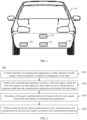
- FIG. 1 is a diagram of an electronic device applicable to a signal synchronization method according to an embodiment of this application.
- the electronic device may be a vehicle, for example, a vehicle 101 shown in FIG. 1 .
- the vehicle 101 may be configured with a plurality of radio communication apparatuses.
- the plurality of radio communication apparatuses may be a vehicle-mounted radar 102, a vehicle-mounted radar 103, a vehicle-mounted radar 104, and a vehicle-mounted radar 105 shown in FIG. 1 .
- a plurality of vehicle-mounted radars in the vehicle 101 may form a distributed radar system to perform joint service measurement, such as target detection, recognition, and distance measurement.
- a prerequisite for the electronic device to perform joint service measurement by using radio signals of the plurality of communication apparatuses is that the radio signals of the plurality of communication apparatuses need to be synchronized with each other.
- the plurality of communication apparatuses share one radio frequency local oscillator, and a local oscillator signal generated by the radio frequency local oscillator is transmitted to the plurality of communication apparatuses through radio frequency cables.
- clock phase accuracy is easily affected by cable changes, such as time, weather, and temperature changes.
- specific materials and processing technologies are required, resulting in high system costs.
- this application proposes that the plurality of radio communication apparatuses may receive an air interface (air interface for short) signal from each other to perform synchronization error measurement, and signal synchronization between the plurality of radio communication apparatuses is implemented after error compensation is performed. Therefore, the electronic device may perform joint service measurement based on the radio signals of the plurality of communication apparatuses.
- air interface air interface for short
- FIG. 2 is a schematic flowchart of a signal synchronization method according to an embodiment of this application.
- the signal synchronization method shown in FIG. 2 may be performed by an electronic device.
- the electronic device is configured with a plurality of communication apparatuses, and each communication apparatus has a radio signal receiving and sending function.
- the electronic device may be a vehicle, and the communication apparatus may be a vehicle-mounted radar.
- this application is not limited thereto.
- the signal synchronization method provided in this application may be used to implement signal synchronization. It should be noted that the signal synchronization method shown in FIG.
- the 2 may be performed by the electronic device, or may be performed by a processing apparatus configured in the electronic device.
- An example in which the method is performed by the electronic device is used below for description. However, this application is not limited thereto. The method includes but is not limited to the following steps.
- S201 The electronic device controls the plurality of communication apparatuses to send a plurality of radio signals, where the plurality of radio signals are orthogonal to each other.
- the electronic device controls the plurality of communication apparatuses to send the radio signals.
- Radio signals between different communication apparatuses are orthogonal to each other, so that the electronic device can separate, from an echo signal received by each communication apparatus, a radio signal sent by the communication apparatus (referred to as a collocated signal, which is sent and received by one communication apparatus) and a radio signal sent by another communication apparatus (referred to as a distributed signal, which is received by the same communication apparatus as the collocated signal), and a signal synchronization error between communication apparatuses is determined based on the distributed signal of the communication apparatus.
- a radio signal sent by the communication apparatus referred to as a collocated signal, which is sent and received by one communication apparatus
- a distributed signal which is received by the same communication apparatus as the collocated signal
- the plurality of radio signals sent by the plurality of communication apparatuses are frequency division multiplexing signals.
- the plurality of signals are orthogonal to each other in frequency domain, and the plurality of radio signals have different initial frequencies.
- the electronic device sets different initial frequencies of the radio signals sent by the plurality of communication apparatuses, so that the radio signals sent by the plurality of communication apparatuses are orthogonal to each other in frequency domain.
- the electronic device may set different initial frequencies of radio signals separately sent by the communication apparatus 1 and the communication apparatus 2.
- the electronic device sets a difference between the initial frequencies of the two communication apparatuses to ⁇ f int .
- f 1 ( t ) represents a frequency of a radio signal sent by the communication apparatus 1 at a moment t
- f 2 ( t ) represents a frequency of a radio signal sent by the communication apparatus 2 at the moment t.
- f 2 t f 1 t + ⁇ f X + ⁇ f int
- ⁇ f X represents a natural frequency error between f 1 ( t ) and f 2 ( t ). That is, ⁇ f X represents a frequency synchronization error between the radio signals that are of the two communication apparatuses and that need to be obtained by the electronic device.
- the electronic device periodically performs signal synchronization error detection, and initial frequency differences in different periods may be different.
- ⁇ ( k ) represents an initial frequency offset coefficient between a radio signal of the communication apparatus 1 and a radio signal of the communication apparatus 2 corresponding to a k th period.
- f 2 t f 1 t + ⁇ f X + ⁇ f int , k
- the plurality of signals are Doppler division multiplexing (Doppler division multiplexing, DDM) signals, and signal pulses of the plurality of signals have different initial phase modulation codewords.
- DDM Doppler division multiplexing
- the electronic device may select, from a DDM codeword set, different initial phase modulation codewords of the signal pulses for the communication apparatus 1 and the communication apparatus 2, so that the radio signals that are sent by the communication apparatus 1 and the communication apparatus 2 and that have different initial phase modulation codewords are orthogonal in Doppler domain.
- a quantity of signal pulses of the communication apparatus is M
- the electronic device selects different codewords from an N-phase DDM codeword set whose length is M as initial phase codewords of the signal pulses of the radio signals of the communication apparatus 1 and the communication apparatus 2.
- Doppler division multiplexing of the radio signal sent by the communication apparatus 1 and the radio signal sent by the communication apparatus 2 is implemented, so that the radio signals sent by different communication apparatuses are orthogonal to each other.
- the plurality of signals are code division multiplexing signals.
- the plurality of signals are orthogonal to each other in code domain, and initial phase modulation codewords of the plurality of signals are different.
- the electronic device may select, from a code division multiplexing (code division multiplexing, CDM) codeword set, different initial phase modulation codewords of the signal pulses for the communication apparatus 1 and the communication apparatus 2, so that the radio signals that are sent by the communication apparatus 1 and the communication apparatus 2 and that have different initial phase modulation codewords are orthogonal to each other in code domain.
- CDM code division multiplexing
- a quantity of signal pulses of the communication apparatus is M
- the electronic device selects different codewords from a CDM codeword set whose length is M as initial phase codewords of the signal pulses of the radio signals of the communication apparatus 1 and the communication apparatus 2.
- initial phase codewords respectively corresponding to a pulse 0, a pulse m, and a pulse M of the radio signal sent by the communication apparatus 1 are C CDM,P 1 (0), C CDM,P 1 (m), and C CDM,P 1 (M).
- Codewords respectively corresponding to a pulse 0, a pulse m, and a pulse M of the radio signal sent by the communication apparatus 2 are C CDM,P 2 (0), C CDM,P 2 (m), and C CDM,P 2 (M).
- Different initial phase codewords of the signal pulses are selected.
- code division multiplexing of the radio signal sent by the communication apparatus 1 and the radio signal sent by the communication apparatus 2 is implemented, so that the radio signals sent by different communication apparatuses are orthogonal to each other in code domain.
- the electronic device may be configured with a plurality of communication apparatuses, and radio signals of the plurality of communication apparatuses may be frequency division multiplexing signals, Doppler division multiplexing signals, or code division multiplexing signals.
- radio signals of the plurality of communication apparatuses may be frequency division multiplexing signals, Doppler division multiplexing signals, or code division multiplexing signals.
- the electronic device controls each communication apparatus to receive a first echo signal, where the first echo signal is an echo signal of a radio signal sent by a communication apparatus other than the communication apparatus receiving the target echo signal.
- the electronic device controls each communication apparatus to receive an echo signal of another communication apparatus. That is, the first echo signal is a distributed signal.
- the echo signal received by each communication apparatus is a second echo signal.
- the second echo signal includes the first echo signal and a third echo signal.
- the third echo signal is an echo signal of a radio signal sent by the communication apparatus receiving the second echo signal.
- the electronic device may separate the first echo signal and the third echo signal from the second echo signal, to obtain the first echo signal. In this case, the electronic device may determine a synchronization error between the radio signals based on the first echo signals received by the plurality of apparatuses.
- the electronic device controls the communication apparatus 1 to send a radio signal A, and the communication apparatus 2 to send a radio signal B.
- An echo signal C (that is, an example of the second echo signal) received by the communication apparatus 1 is a mixed signal of an echo signal (that is, an example of the third echo signal) of the radio signal A and an echo signal (that is, an example of the first echo signal) of the radio signal B.
- the communication apparatus may obtain the echo signal of the radio signal A and the echo signal of the radio signal B through separation of the echo signal C.
- the echo signal of the radio signal A from the communication apparatus 1 may be obtained in a similar manner.
- the communication apparatus sends the radio signal through a synchronization channel, and receives the echo signal of the radio signal through the synchronization channel.
- a transmit and receive antenna (denoted as a TRX) is configured on the synchronization channel, and the transmit and receive antenna may receive a signal and send a signal.
- the communication apparatus (for example, the communication apparatus 1 and the communication apparatus 2) includes the transmit and receive antenna TRX, and the communication apparatus may further include a receive antenna and a transmit antenna.
- the receive antenna can only receive a signal, and the transmit antenna can only send a signal.
- the communication apparatus 1 sends a radio signal 1 through a TRX 1, and receives an echo signal of a radio signal 2 through the TRX 1.
- the communication apparatus 2 sends the radio signal 2 through a TRX 2, and receives an echo signal of the radio signal 1 through the TRX 2.
- the radio signal 1 and the radio signal 2 have reciprocity. That is, a propagation path of the radio signal 1 is the same as a propagation path of the radio signal 2.
- the path of the radio signal 1 is from the TRX 1 to the target, and then the radio signal 1 is reflected from the target to the TRX 2.
- the path of the radio signal 2 is from the TRX 2 to the target, and then the radio signal 2 is reflected from the target to the TRX 1. Inaccurate synchronization error estimation caused by inconsistent propagation paths and caused by receiving and sending signals by different antennas can be avoided.
- S203 The electronic device determines a first signal synchronization error based on the first echo signals received by the plurality of communication apparatuses.
- the synchronization error includes one or more of a time error, a frequency error, and a phase error between the plurality of radio signals.
- the communication apparatus may determine a signal frequency error based on the first echo signals received by the plurality of communication apparatuses. For example, the communication apparatus 1 performs frequency mixing by using a local oscillator signal of the communication apparatus 1 and the echo signal that is of the radio signal 2 and that is received from the communication apparatus 2, to obtain a beat frequency corresponding to the radio signal 2, where the beat frequency is f b 12 ( t ). The communication apparatus 2 performs frequency mixing by using a local oscillator signal of the communication apparatus 2 and the echo signal that is of the radio signal 1 and that is received from the communication apparatus 1, to obtain a beat frequency corresponding to the radio signal 1, where the beat frequency is f b 21 ( t ) .
- ⁇ f X may be used as a frequency error in the first signal synchronization error, and the electronic device may perform compensation for a to-be-sent signal of each communication apparatus based on ⁇ f X .
- ⁇ f X is a second signal synchronization error.
- the electronic device performs filtering based on the second signal synchronization error and a third signal synchronization error, to determine the first signal synchronization error.
- the third signal synchronization error is a signal synchronization error determined in a period before the period k.
- the electronic device After filtering in the period k-1, the electronic device obtains a frequency error ⁇ f X,k -1 (that is, an example of the third signal synchronization error).
- the electronic device may filter the signal synchronization error in a filtering manner such as Alpha (Alpha filtering) or Kalman (Kalman) filtering.
- Alpha Alpha filtering
- Kalman Kalman filtering
- ⁇ f ⁇ ⁇ ⁇
- the radio signal sent by the communication apparatus is an FMCW signal
- ⁇ f may be the foregoing ⁇ f X or ⁇ f X,k .
- S ADC 12 ( t ) is an echo analog-to-digital converter (analog-to-digital converter, ADC) signal that is received by the communication apparatus 1 and that is from the communication apparatus 2, namely, a digital signal obtained by analog-to-digital conversion on the echo signal of the radio signal 2.
- S ADC 21 ( t ) is an echo ADC signal that is received by the communication apparatus 2 and that is from the communication apparatus 1, namely, a digital signal obtained by analog-to-digital conversion on the echo signal of the radio signal 1.
- S204 The electronic device performs, based on the first signal synchronization error, synchronization error compensation for the first echo signal received by each communication apparatus.
- the electronic device may perform the synchronization error compensation for the received signal of the communication apparatus.
- the synchronization error compensation may be performed according to the following formula, to separately obtain compensated signals S ADC 12 ′ and S ADC 21 ′ .
- S ADC 12 ′ t i S ADC 12 t i ⁇ e ⁇ j ⁇ ⁇ t + 2 ⁇ t ⁇ ⁇ f
- S ADC 21 ′ t i S ADC 21 t i ⁇ e ⁇ j ⁇ ⁇ t ⁇ 2 ⁇ t ⁇ ⁇ f
- ⁇ f may be the foregoing ⁇ f X or ⁇ f X,k .
- the electronic device may determine the first signal synchronization error based on the first echo signal received by one receive channel of each of the plurality of communication apparatuses. After obtaining the first signal synchronization error, the electronic device performs, based on the first signal synchronization error, synchronization error compensation for the first echo signal received by each receive channel of the communication apparatus.
- the electronic device performs, based on a first signal synchronization error received by the foregoing synchronization channel configured with the transmit and receive antenna TRX, synchronization error compensation for the first echo signal received by each receive channel of the communication apparatus. Specifically, based on the first signal synchronization error, the electronic device performs synchronization error compensation for the first echo signal received by the synchronization channel (the synchronization channel belongs to both the send channel and the receive channel) of the communication apparatus, and performs synchronization error compensation for a first echo signal received by another receive channel of the communication apparatus.
- the electronic device may perform service measurement based on the compensated signals S ADC 12 ′ and S ADC 21 ′ .
- the electronic device may perform service measurement after performing synchronization error compensation for the distributed signal.
- the electronic device may perform error compensation for the collocated signal based on a service measurement requirement and a signal synchronization error obtained through measurement. In this case, corresponding service measurement is performed based on the compensated echo signals of the different communication apparatuses.
- the electronic device may further separately perform parameter adjustment on radio signals of a next frame (or a next detection period) of the plurality of communication apparatuses based on the synchronization error (for example, the time error and the frequency error) obtained through measurement.
- the synchronization error for example, the time error and the frequency error
- the electronic device may perform frequency error compensation for next-frame radio signals of the plurality of communication apparatuses based on the frequency error ⁇ f , so that both time and frequencies of the radio signals of the plurality of communication apparatuses are synchronized.
- the electronic device may perform time error compensation for next-frame radio signals of the plurality of communication apparatuses based on the obtained ⁇ ⁇ , so that both time and frequencies of the radio signals of the plurality of communication apparatuses are synchronized.
- the electronic device may perform both the time compensation and the frequency compensation for the next-frame radio signals of the plurality of communication apparatuses.
- a compensation amount of the time compensation performed by the electronic device on the radio signal is ⁇ ⁇ 1
- a compensation amount of the frequency compensation is ⁇ f 1 .
- the error compensation may be performed in one of the foregoing implementations based on an implementation requirement. This is not limited in this application.
- the electronic device may be a vehicle.
- the vehicle may be configured with a plurality of radars.
- the vehicle may implement synchronization of radio signals of the plurality of radars by using the signal synchronization method provided in embodiments of this application.
- the vehicle may be configured with two radars, for example, a radar 1 and a radar 2.
- the radar 1 sends a radio signal 1, and the radar 2 sends a radio signal 2.
- the radio signal 1 and the radio signal 2 are orthogonal to each other.
- An echo signal 1 received by the radar 1 includes an echo signal (namely, a collocated signal, for example, S 11 shown in FIG. 6 ) of the radio signal 1 and an echo signal (namely, a remote signal, for example, S 12 shown in FIG.
- An echo signal 2 received by the radar 2 includes an echo signal (namely, a collocated signal, for example, S 22 shown in FIG. 6 ) of the radio signal 2 and an echo signal (namely, a remote signal, for example, S 21 shown in FIG. 6 ) of the radio signal 1.
- the vehicle separately performs signal separation on the echo signal 1 and the echo signal 2, and separately obtains the collocated signal and distributed signal.
- the collocated signal may be used for monostatic target detection and estimation.
- the vehicle estimates a signal synchronization error, for example, one or more of a frequency error, a time error, and a phase error, based on the distributed signal obtained through the signal separation.
- distributed signals are the echo signal that is of the radio signal 2 and that is received by the radar 1 and the echo signal that is of the radio signal 1 and that is received by the radar 2.
- the echo signal is compensated based on the signal synchronization error, and the compensated echo signal may be used for multistatic joint detection and estimation.
- signal synchronization error measurement is performed by using the radio signals received by the plurality of radio communication apparatuses from each other, and signal synchronization between the plurality of radio communication apparatuses is implemented after the error compensation is performed. Therefore, the electronic device may perform joint service measurement based on the radio signals of the plurality of communication apparatuses. This improves detection sensitivity, measurement accuracy, and resolution.
- FIG. 7 is a diagram of a structure of a signal synchronization apparatus according to an embodiment of this application.
- the signal synchronization apparatus may be implemented by using software, hardware, or a combination thereof, and is referred to as an electronic device or a part of an electronic device.
- the signal synchronization apparatus may include a control unit 701 and a processing unit 702.
- the control unit 701 is configured to: control a plurality of communication apparatuses to send a plurality of radio signals, where the plurality of radio signals are orthogonal to each other; and control each communication apparatus to receive a first echo signal, where the first echo signal is an echo signal of a radio signal sent by a communication apparatus other than the communication apparatus receiving the first echo signal.
- the processing unit 702 is configured to: determine a first signal synchronization error based on the first echo signals received by the plurality of communication apparatuses, and perform, based on the first signal synchronization error, synchronization error compensation for the first echo signal received by each communication apparatus.
- the signal synchronization apparatus periodically detects a signal synchronization error between the plurality of communication apparatuses.
- the processing unit 702 is specifically configured to obtain a second signal synchronization error in a target detection period based on the first echo signals received by the plurality of communication apparatuses, and filter the second signal synchronization error and a third signal synchronization error, to determine the first signal synchronization error.
- the third signal synchronization error is a signal synchronization error determined in a period before the target detection period.
- control unit 701 is specifically configured to control each communication apparatus to receive a second echo signal.
- the second echo signal includes a third echo signal and the first echo signal.
- the third echo signal is an echo signal of a radio signal sent by the communication apparatus receiving the second echo signal.
- the processing unit 702 is further configured to separate the third echo signal and the first echo signal from the second echo signal.
- the processing unit 702 is further configured to perform service measurement based on the third echo signal.
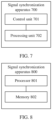
- FIG. 8 is another diagram of a structure of a signal synchronization apparatus according to an embodiment of this application.
- the signal synchronization apparatus includes a processor 801 and a memory 802.
- the memory 802 is configured to store a computer program.
- the processor 801 is configured to execute the computer program in the memory 802, to implement the signal synchronization method provided in the embodiment shown in FIG. 2 .
- FIG. 2 For details, refer to the descriptions in the foregoing method embodiments. For brevity, details are not described herein again.
- the memory 802 may alternatively be integrated into the processor 801, or may be independent of the processor 801.
- the processor 801 may correspond to the processing unit 702 in FIG. 7 .
- An embodiment of this application further provides a processing apparatus, including a processor and a (communication) interface.
- the processor is configured to perform the method in the foregoing embodiments shown in FIG. 2 .
- the processing apparatus may be one or more chips.
- the processing apparatus may be a field programmable gate array (field programmable gate array, FPGA), an application-specific integrated circuit (application-specific integrated circuit, ASIC), a system on chip (system on chip, SoC), a central processing unit (central processor unit, CPU), a network processor (network processor, NP), a digital signal processing circuit (digital signal processor, DSP), a micro controller unit (micro controller unit, MCU), a programmable logic device (programmable logic device, PLD), or another integrated chip.
- field programmable gate array field programmable gate array
- ASIC application-specific integrated circuit
- SoC system on chip
- CPU central processing unit
- CPU central processor unit
- NP network processor
- DSP digital signal processing circuit
- micro controller unit micro controller unit
- MCU programmable logic device
- PLD programmable logic device
- this application further provides a computer program product.
- the computer program product includes computer program code.
- an apparatus including the processor is enabled to perform the method in the embodiment shown in FIG. 2 .
- All or some of the technical solutions provided in embodiments of this application may be implemented by using software, for example, may be implemented in a form of a computer program product.
- the computer program product includes one or more computer instructions. When the computer program instructions are loaded and executed on a computer, some or all of the procedures or functions of the method provided in embodiments of this application are generated.
- this application further provides a computer-readable storage medium.
- the computer-readable storage medium stores program code.
- an apparatus including the processor is enabled to perform the method in the embodiment shown in FIG. 2 .
- the computer-readable storage medium may be any usable medium accessible by a computer, or a data storage device integrating one or more usable media.
- the readable medium may be a magnetic medium (for example, a floppy disk, a hard disk drive, or a magnetic tape), an optical medium (for example, a digital video disc (digital video disc, DVD)), a semiconductor medium, or the like.
- the disclosed apparatus and method may be implemented in other manners.
- the described apparatus embodiments are merely examples.
- division into the units is merely logical function division and may be other division in actual implementation.
- a plurality of units or components may be combined or integrated into another system, or some features may be ignored or not performed.
- the displayed or discussed mutual couplings or direct couplings or communication connections may be implemented by using some interfaces.
- the indirect couplings or communication connections between the apparatuses or units may be implemented in electronic, mechanical, or other forms.
- the units described as separate parts may or may not be physically separate, and parts displayed as units may or may not be physical units, in other words, may be located in one location, or may be distributed on a plurality of network units. Some or all of the units may be selected based on actual requirements to achieve the objectives of the solutions of embodiments.
Landscapes
- Engineering & Computer Science (AREA)
- Radar, Positioning & Navigation (AREA)
- Remote Sensing (AREA)
- Computer Networks & Wireless Communication (AREA)
- Physics & Mathematics (AREA)
- General Physics & Mathematics (AREA)
- Signal Processing (AREA)
- Electromagnetism (AREA)
- Mobile Radio Communication Systems (AREA)
- Synchronisation In Digital Transmission Systems (AREA)
Abstract
Description
- This application claims priority to
Chinese Patent Application No. 202210178255.1, filed with the China National Intellectual Property Administration on February 24, 2022 - This application relates to the communication field, and more specifically, to a signal synchronization method, an apparatus, and a readable storage medium.
- In an autonomous driving system, a single radar sensor, with a limited detection angle and distance range, may not be sensitive or accurate enough to detect some targets. On this basis, a plurality of radars can be combined to form a distributed radar system for data interaction and joint processing, improving detection sensitivity, measurement accuracy, resolution, and the like.
- To implement joint processing of data of the plurality of radars in the distributed radar system, signal synchronization needs to be performed between the plurality of radars. A common distributed synchronization technology is co-local oscillation. That is, the plurality of radars share one radio frequency local oscillator, and a local oscillator signal sent by the radio frequency local oscillator is transmitted to the plurality of radars through radio frequency cables. In this synchronization manner, clock phase accuracy is easily affected by cable changes, such as time, weather, and temperature changes. To improve cable phase stability, specific materials and processing technologies are required, resulting in high system costs.
- This application provides a signal synchronization method, an apparatus, and a readable storage medium, so that signal synchronization can be implemented while hardware costs are reduced.
- According to a first aspect, a signal synchronization method is provided. The method may be performed by an electronic device or a module (for example, a chip) configured on (or configured for) the electronic device.
- The method includes: controlling a plurality of communication apparatuses to send a plurality of radio signals, where the plurality of radio signals are orthogonal to each other; controlling each communication apparatus to receive a first echo signal, where the first echo signal is an echo signal of a radio signal sent by a communication apparatus other than the communication apparatus receiving the first echo signal; determining a first signal synchronization error based on the first echo signals received by the plurality of communication apparatuses; and performing, based on the first signal synchronization error, synchronization error compensation for the first echo signal received by each communication apparatus.
- In the foregoing solution, according to the signal synchronization method provided in this application, signal synchronization error measurement is performed by using radio signals received by a plurality of radio communication apparatuses from each other, and signal synchronization between the plurality of radio communication apparatuses is implemented after error compensation is performed. Therefore, the electronic device may perform joint service measurement based on the radio signals of the plurality of communication apparatuses. This improves detection sensitivity, measurement accuracy, and resolution. In addition, implementation costs of signal synchronization can be reduced.
- With reference to the first aspect, in some implementations of the first aspect, the plurality of radio signals are frequency division multiplexing signals, and the plurality of radio signals have different initial frequencies.
- With reference to the first aspect, in some implementations of the first aspect, the plurality of radio signals are code division multiplexing signals or Doppler division multiplexing signals, and signal pulses of the plurality of radio signals have different initial phase modulation codewords.
- In the foregoing solution, the plurality of radio signals are frequency division multiplexing signals, Doppler division multiplexing signals, or code division multiplexing signals. To be specific, radio signals sent by different communication apparatuses are orthogonal to each other, so that an echo signal of a radio signal from another communication apparatus can be obtained through separation of a mixed signal received by the communication apparatus, to estimate a synchronization error between signals.
- With reference to the first aspect, in some implementations of the first aspect, the synchronization error includes one or more of a time error, a frequency error, and a phase error between the plurality of radio signals.
- With reference to the first aspect, in some implementations of the first aspect, a signal synchronization error between the plurality of communication apparatuses is periodically detected, and the determining a first signal synchronization error based on the first echo signals received by the plurality of communication apparatuses includes: obtaining a second signal synchronization error in a target detection period based on the first echo signals received by the plurality of communication apparatuses; and filtering the second signal synchronization error and a third signal synchronization error, to determine the first signal synchronization error, where the third signal synchronization error is a signal synchronization error determined in a period before the target detection period.
- With reference to the first aspect, in some implementations of the first aspect, the controlling each communication apparatus to receive a first echo signal includes: controlling each communication apparatus to receive a second echo signal, where the second echo signal includes a third echo signal and the first echo signal, and the third echo signal is an echo signal of a radio signal sent by the communication apparatus receiving the second echo signal; separating the third echo signal and the first echo signal from the second echo signal; and performing service measurement based on the third echo signal.
- In the foregoing solution, signal synchronization error estimation and compensation, and echo signal-based service measurement can be implemented at the same time, improving detection efficiency.
- According to a second aspect, a signal synchronization apparatus is provided. In a design, the apparatus may include a module in a one-to-one correspondence with the method/operation/step/action described in the first aspect. The module may be a hardware circuit or software, or may be implemented in a combination of the hardware circuit and the software. In a design, the apparatus includes: a control unit, configured to control a plurality of communication apparatuses to send a plurality of radio signals, where the plurality of radio signals are orthogonal to each other; and the control unit is further configured to control each communication apparatus to receive a first echo signal, and the first echo signal is an echo signal of a radio signal sent by a communication apparatus other than the communication apparatus receiving the first echo signal; and a processing unit, configured to determine a first signal synchronization error based on the first echo signals received by the plurality of communication apparatuses; and the processing unit is further configured to perform, based on the first signal synchronization error, synchronization error compensation for the first echo signal received by each communication apparatus.
- With reference to the second aspect, in some implementations of the second aspect, the plurality of radio signals are frequency division multiplexing signals, and the plurality of radio signals have different initial frequencies.
- With reference to the second aspect, in some implementations of the second aspect, the plurality of radio signals are code division multiplexing signals or Doppler division multiplexing signals, and signal pulses of the plurality of radio signals have different initial phase modulation codewords.
- With reference to the second aspect, in some implementations of the second aspect, the synchronization error includes one or more of a time error, a frequency error, and a phase error between the plurality of radio signals.
- With reference to the second aspect, in some implementations of the second aspect, a signal synchronization error between the plurality of communication apparatuses is periodically detected, and the processing unit is specifically configured to:
- obtain a second signal synchronization error in a target detection period based on the first echo signals received by the plurality of communication apparatuses; and
- filter the second signal synchronization error and a third signal synchronization error, to determine the first signal synchronization error, where the third signal synchronization error is a signal synchronization error determined in a period before the target detection period.
- With reference to the second aspect, in some implementations of the second aspect, the control unit is specifically configured to control each communication apparatus to receive a second echo signal, the second echo signal includes a third echo signal and the first echo signal, and the third echo signal is an echo signal of a radio signal sent by the communication apparatus receiving the second echo signal; the processing unit is further configured to separate the third echo signal and the first echo signal from the second echo signal; and the processing unit is further configured to perform service measurement based on the third echo signal.
- According to a third aspect, a signal synchronization apparatus is provided, including a processor. The processor may implement the method according to any one of the first aspect and the possible implementations of the first aspect. Optionally, the signal synchronization apparatus further includes a memory. The processor is coupled to the memory, and may be configured to execute instructions in the memory, to implement the method according to any one of the first aspect and the possible implementations of the first aspect. Optionally, the signal synchronization apparatus further includes a communication interface, and the processor is coupled to the communication interface.
- In an implementation, the signal synchronization apparatus is an electronic device. The communication interface may be a transceiver or an input/output interface.
- In another implementation, the signal synchronization apparatus is a chip configured in the electronic device. When the signal synchronization apparatus is a chip configured in the electronic device, the communication interface may be an input/output interface.
- Optionally, the transceiver may be a transceiver circuit. Optionally, the input/output interface may be an input/output circuit.
- According to a fourth aspect, a processor is provided, including an input circuit, an output circuit, and a processing circuit. The processing circuit is configured to receive a signal through the input circuit, and transmit the signal through the output circuit, to enable the processor to perform the method according to any one of the first aspect and the possible implementations of the first aspect.
- In a specific implementation process, the processor may be one or more chips. The input circuit may be an input pin. The output circuit may be an output pin. The processing circuit may be a transistor, a gate circuit, a trigger, any logic circuit, or the like. An input signal received by the input circuit may be received and input by, for example, but not limited to, a receiver. A signal output by the output circuit may be output to, for example, but not limited to, a transmitter and transmitted by the transmitter. In addition, the input circuit and the output circuit may be a same circuit, where the circuit is used as the input circuit and the output circuit at different moments. A specific implementation of the processor and the various circuits are not limited in embodiments of this application.
- According to a fifth aspect, a computer program product is provided. The computer program product includes a computer program (which may also be referred to as code or instructions). When the computer program is run, a computer is enabled to perform the method according to any one of the first aspect and the possible implementations of the first aspect.
- According to a sixth aspect, a computer-readable storage medium is provided. The computer-readable storage medium stores a computer program (which may also be referred to as code or instructions). When the computer program is run on a computer, the computer is enabled to perform the method according to any one of the first aspect and the possible implementations of the first aspect.
-
-
FIG. 1 is a diagram of an electronic device applicable to a signal synchronization method according to an embodiment of this application; -
FIG. 2 is a schematic flowchart of a signal synchronization method according to an embodiment of this application; -
FIG. 3 is a diagram of frequency division multiplexing of a plurality of radio signals according to an embodiment of this application; -
FIG. 4 is a diagram of code division multiplexing of a plurality of radio signals according to an embodiment of this application; -
FIG. 5 is a diagram of a transmit and receive antenna of a communication apparatus according to an embodiment of this application; -
FIG. 6 is another schematic flowchart of a signal synchronization method according to an embodiment of this application; -
FIG. 7 is a diagram of a structure of a signal synchronization apparatus according to an embodiment of this application; and -
FIG. 8 is another diagram of a structure of a signal synchronization apparatus according to an embodiment of this application. - To clearly describe the technical solutions in embodiments of this application, words such as "first" and "second" are used in embodiments of this application to distinguish between same items or similar items that provide basically same functions or purposes. For example, a first network and a second network are merely intended to distinguish between different networks, and are not intended to limit a sequence thereof. A person skilled in the art may understand that the words such as "first" and "second" do not limit a quantity or an execution sequence, and the words such as "first" and "second" do not indicate a definite difference.
- It should be noted that, in this application, words "example" or "for example" are used to represent giving an example, an illustration, or a description. Any embodiment or design solution described as an "example" or "for example" in this application should not be explained as being more preferred or having more advantages than another embodiment or design solution. To be precise, the words such as "example" or "for example" are intended to present a related concept in a specific manner.
- The following describes technical solutions of this application with reference to accompanying drawings.
- The technical solutions provided in embodiments of this application may be applied to an electronic device configured with a plurality of radio communication apparatuses.
FIG. 1 is a diagram of an electronic device applicable to a signal synchronization method according to an embodiment of this application. As shown inFIG. 1 , the electronic device may be a vehicle, for example, avehicle 101 shown inFIG. 1 . Thevehicle 101 may be configured with a plurality of radio communication apparatuses. The plurality of radio communication apparatuses may be a vehicle-mountedradar 102, a vehicle-mountedradar 103, a vehicle-mountedradar 104, and a vehicle-mountedradar 105 shown inFIG. 1 . A plurality of vehicle-mounted radars in thevehicle 101 may form a distributed radar system to perform joint service measurement, such as target detection, recognition, and distance measurement. - However, a prerequisite for the electronic device to perform joint service measurement by using radio signals of the plurality of communication apparatuses is that the radio signals of the plurality of communication apparatuses need to be synchronized with each other. Currently, in a conventional synchronization technology, the plurality of communication apparatuses share one radio frequency local oscillator, and a local oscillator signal generated by the radio frequency local oscillator is transmitted to the plurality of communication apparatuses through radio frequency cables. In this synchronization manner, clock phase accuracy is easily affected by cable changes, such as time, weather, and temperature changes. To improve cable phase stability, specific materials and processing technologies are required, resulting in high system costs.
- For a problem that the sharing of one radio frequency local oscillator by the plurality of radio communication apparatuses is easily affected by a cable change, this application proposes that the plurality of radio communication apparatuses may receive an air interface (air interface for short) signal from each other to perform synchronization error measurement, and signal synchronization between the plurality of radio communication apparatuses is implemented after error compensation is performed. Therefore, the electronic device may perform joint service measurement based on the radio signals of the plurality of communication apparatuses.
- The following describes the signal synchronization method provided in this application with reference to the accompanying drawings.
-
FIG. 2 is a schematic flowchart of a signal synchronization method according to an embodiment of this application. The signal synchronization method shown inFIG. 2 may be performed by an electronic device. The electronic device is configured with a plurality of communication apparatuses, and each communication apparatus has a radio signal receiving and sending function. The electronic device may be a vehicle, and the communication apparatus may be a vehicle-mounted radar. However, this application is not limited thereto. When the electronic device having a plurality of radio communication apparatuses needs to perform joint processing on signals of the plurality of radio communication apparatuses, the signal synchronization method provided in this application may be used to implement signal synchronization. It should be noted that the signal synchronization method shown inFIG. 2 may be performed by the electronic device, or may be performed by a processing apparatus configured in the electronic device. An example in which the method is performed by the electronic device is used below for description. However, this application is not limited thereto. The method includes but is not limited to the following steps. - S201: The electronic device controls the plurality of communication apparatuses to send a plurality of radio signals, where the plurality of radio signals are orthogonal to each other.
- The electronic device controls the plurality of communication apparatuses to send the radio signals. Radio signals between different communication apparatuses are orthogonal to each other, so that the electronic device can separate, from an echo signal received by each communication apparatus, a radio signal sent by the communication apparatus (referred to as a collocated signal, which is sent and received by one communication apparatus) and a radio signal sent by another communication apparatus (referred to as a distributed signal, which is received by the same communication apparatus as the collocated signal), and a signal synchronization error between communication apparatuses is determined based on the distributed signal of the communication apparatus.
- In an implementation, the plurality of radio signals sent by the plurality of communication apparatuses are frequency division multiplexing signals. In other words, the plurality of signals are orthogonal to each other in frequency domain, and the plurality of radio signals have different initial frequencies.
- The electronic device sets different initial frequencies of the radio signals sent by the plurality of communication apparatuses, so that the radio signals sent by the plurality of communication apparatuses are orthogonal to each other in frequency domain.
- For example, two communication apparatuses, namely, a
communication apparatus 1 and acommunication apparatus 2, are used. The electronic device may set different initial frequencies of radio signals separately sent by thecommunication apparatus 1 and thecommunication apparatus 2. For example, the electronic device sets a difference between the initial frequencies of the two communication apparatuses to Δfint . For example, as shown inFIG. 3 , f 1(t) represents a frequency of a radio signal sent by thecommunication apparatus 1 at a moment t, and f 2 (t) represents a frequency of a radio signal sent by thecommunication apparatus 2 at the moment t. In this case,
- ΔfX represents a natural frequency error between f 1(t) and f 2(t). That is, ΔfX represents a frequency synchronization error between the radio signals that are of the two communication apparatuses and that need to be obtained by the electronic device.
- Optionally, the electronic device periodically performs signal synchronization error detection, and initial frequency differences in different periods may be different.
- For example, an initial frequency difference Δfint,k between the two communication apparatuses in a period k in the foregoing example may be:

- α(k) represents an initial frequency offset coefficient between a radio signal of the
communication apparatus 1 and a radio signal of thecommunication apparatus 2 corresponding to a kth period. In this case,
- In another implementation, the plurality of signals are Doppler division multiplexing (Doppler division multiplexing, DDM) signals, and signal pulses of the plurality of signals have different initial phase modulation codewords.
- The electronic device may select, from a DDM codeword set, different initial phase modulation codewords of the signal pulses for the
communication apparatus 1 and thecommunication apparatus 2, so that the radio signals that are sent by thecommunication apparatus 1 and thecommunication apparatus 2 and that have different initial phase modulation codewords are orthogonal in Doppler domain. For example, a quantity of signal pulses of the communication apparatus is M, and the electronic device selects different codewords from an N-phase DDM codeword set whose length is M as initial phase codewords of the signal pulses of the radio signals of thecommunication apparatus 1 and thecommunication apparatus 2. - For example, if the electronic device selects a q 1 th codeword in the N-phase DDM codeword set for the
communication apparatus 1, an initial phase modulation codeword of the mth radio signal pulse of thecommunication apparatus 1 is CDDM (m, q 1) = e j*sign*2π*q1 *m/ N, where sign = ±1, m = 0,1,2, ..., M - 1. If the electronic device selects a q 2 th codeword in the N-phase DDM codeword set for thecommunication apparatus 2, an initial phase modulation codeword of the mth radio signal pulse of thecommunication apparatus 1 is CDDM (m, q 2) = e j*sign*2π*q2 *m/ N, where q 1 ≠ q 2. Doppler division multiplexing of the radio signal sent by thecommunication apparatus 1 and the radio signal sent by thecommunication apparatus 2 is implemented, so that the radio signals sent by different communication apparatuses are orthogonal to each other. - In still another implementation, the plurality of signals are code division multiplexing signals. In other words, the plurality of signals are orthogonal to each other in code domain, and initial phase modulation codewords of the plurality of signals are different.
- The electronic device may select, from a code division multiplexing (code division multiplexing, CDM) codeword set, different initial phase modulation codewords of the signal pulses for the
communication apparatus 1 and thecommunication apparatus 2, so that the radio signals that are sent by thecommunication apparatus 1 and thecommunication apparatus 2 and that have different initial phase modulation codewords are orthogonal to each other in code domain. For example, a quantity of signal pulses of the communication apparatus is M, and the electronic device selects different codewords from a CDM codeword set whose length is M as initial phase codewords of the signal pulses of the radio signals of thecommunication apparatus 1 and thecommunication apparatus 2. - For example, a bi-phase random code in the CDM codeword set is CCDM,P (m) = e j*P(m) . P represents a sequence whose length is M, and a value P(m) in the sequence is 0 or 1, where m = 0,1,2, ..., M - 1. In this case, a pulse initial phase modulation codeword selected by the electronic device for the
communication apparatus 1 is C CDM,P1 (m) = e j*P1 (m), and a pulse initial phase modulation codeword selected by the electronic device for thecommunication apparatus 2 is C CDM,P2 (m) = e j*P2 (m), where P 1 ≠ P 2.FIG. 4 is a diagram of the radio signal sent by thecommunication apparatus 1 and the radio signal sent by thecommunication apparatus 2. As shown inFIG. 4 , initial phase codewords respectively corresponding to apulse 0, a pulse m, and a pulse M of the radio signal sent by thecommunication apparatus 1 are C CDM,P1 (0), C CDM,P1 (m), and C CDM,P1 (M). Codewords respectively corresponding to apulse 0, a pulse m, and a pulse M of the radio signal sent by thecommunication apparatus 2 are C CDM,P2 (0), C CDM,P2 (m), and C CDM,P2 (M). Different initial phase codewords of the signal pulses are selected. In this case, code division multiplexing of the radio signal sent by thecommunication apparatus 1 and the radio signal sent by thecommunication apparatus 2 is implemented, so that the radio signals sent by different communication apparatuses are orthogonal to each other in code domain. - It should be noted that the foregoing uses two communication apparatuses of the electronic device as an example for description. However, this application is not limited thereto. The electronic device may be configured with a plurality of communication apparatuses, and radio signals of the plurality of communication apparatuses may be frequency division multiplexing signals, Doppler division multiplexing signals, or code division multiplexing signals. For a specific implementation, refer to the foregoing descriptions of the two communication apparatuses. For brevity, details are not described herein again.
- S202: The electronic device controls each communication apparatus to receive a first echo signal, where the first echo signal is an echo signal of a radio signal sent by a communication apparatus other than the communication apparatus receiving the target echo signal.
- In other words, the electronic device controls each communication apparatus to receive an echo signal of another communication apparatus. That is, the first echo signal is a distributed signal.
- Specifically, the echo signal received by each communication apparatus is a second echo signal. The second echo signal includes the first echo signal and a third echo signal. The third echo signal is an echo signal of a radio signal sent by the communication apparatus receiving the second echo signal. The electronic device may separate the first echo signal and the third echo signal from the second echo signal, to obtain the first echo signal. In this case, the electronic device may determine a synchronization error between the radio signals based on the first echo signals received by the plurality of apparatuses.
- For example, the electronic device controls the
communication apparatus 1 to send a radio signal A, and thecommunication apparatus 2 to send a radio signal B. An echo signal C (that is, an example of the second echo signal) received by thecommunication apparatus 1 is a mixed signal of an echo signal (that is, an example of the third echo signal) of the radio signal A and an echo signal (that is, an example of the first echo signal) of the radio signal B. After the electronic device receives the echo signal C received by thecommunication apparatus 1, because the radio signal A and the radio signal B are orthogonal to each other, the communication apparatus may obtain the echo signal of the radio signal A and the echo signal of the radio signal B through separation of the echo signal C. For the echo signal received by thecommunication apparatus 2, the echo signal of the radio signal A from thecommunication apparatus 1 may be obtained in a similar manner. - Optionally, the communication apparatus sends the radio signal through a synchronization channel, and receives the echo signal of the radio signal through the synchronization channel. In other words, a transmit and receive antenna (denoted as a TRX) is configured on the synchronization channel, and the transmit and receive antenna may receive a signal and send a signal.
- For example, as shown in
FIG. 5 , the communication apparatus (for example, thecommunication apparatus 1 and the communication apparatus 2) includes the transmit and receive antenna TRX, and the communication apparatus may further include a receive antenna and a transmit antenna. The receive antenna can only receive a signal, and the transmit antenna can only send a signal. Thecommunication apparatus 1 sends aradio signal 1 through aTRX 1, and receives an echo signal of aradio signal 2 through theTRX 1. Thecommunication apparatus 2 sends theradio signal 2 through aTRX 2, and receives an echo signal of theradio signal 1 through theTRX 2. In this case, theradio signal 1 and theradio signal 2 have reciprocity. That is, a propagation path of theradio signal 1 is the same as a propagation path of theradio signal 2. For example, the path of theradio signal 1 is from theTRX 1 to the target, and then theradio signal 1 is reflected from the target to theTRX 2. The path of theradio signal 2 is from theTRX 2 to the target, and then theradio signal 2 is reflected from the target to theTRX 1. Inaccurate synchronization error estimation caused by inconsistent propagation paths and caused by receiving and sending signals by different antennas can be avoided. - S203: The electronic device determines a first signal synchronization error based on the first echo signals received by the plurality of communication apparatuses.
- Optionally, the synchronization error includes one or more of a time error, a frequency error, and a phase error between the plurality of radio signals.
- The communication apparatus may determine a signal frequency error based on the first echo signals received by the plurality of communication apparatuses. For example, the
communication apparatus 1 performs frequency mixing by using a local oscillator signal of thecommunication apparatus 1 and the echo signal that is of theradio signal 2 and that is received from thecommunication apparatus 2, to obtain a beat frequency corresponding to theradio signal 2, where the beat frequency is f b12(t). Thecommunication apparatus 2 performs frequency mixing by using a local oscillator signal of thecommunication apparatus 2 and the echo signal that is of theradio signal 1 and that is received from thecommunication apparatus 1, to obtain a beat frequency corresponding to theradio signal 1, where the beat frequency is f b21(t). In this case, the electronic device may obtain, based on f b12(t) and f b21(t), a frequency error ΔfX between the radio signals of the two communication apparatuses as follows:
- If the radio signals sent by the two communication apparatuses have different initial frequency differences in different periods, for example, an initial frequency difference of the radio signals sent by the two communication apparatuses in a period k is Δfint,k = α(k)Δfint, the electronic device may obtain, based on f b12(t) and f b21(t), the frequency error ΔfX between the radio signals of the two communication apparatuses as follows:

- ΔfX may be used as a frequency error in the first signal synchronization error, and the electronic device may perform compensation for a to-be-sent signal of each communication apparatus based on ΔfX.
- Optionally, ΔfX is a second signal synchronization error. The electronic device performs filtering based on the second signal synchronization error and a third signal synchronization error, to determine the first signal synchronization error. The third signal synchronization error is a signal synchronization error determined in a period before the period k.
- For example, after filtering in the period k-1, the electronic device obtains a frequency error Δf X,k-1 (that is, an example of the third signal synchronization error). After obtaining a frequency error ΔfX (that is, an example of the second signal synchronization error) in the period k, the communication apparatus filters Δf X,k-1 and ΔfX to obtain a frequency error ΔfX,k in the first signal synchronization error, where

- The electronic device may filter the signal synchronization error in a filtering manner such as Alpha (Alpha filtering) or Kalman (Kalman) filtering. However, this application is not limited thereto.
- For a frequency-modulated continuous wave (frequency-modulated continuous wave, FMCW) signal, a relationship between a signal frequency error Δf and a time error Δτ is as follows:

- For example, if the radio signal sent by the communication apparatus is an FMCW signal, after the electronic device obtains the frequency error between the plurality of radio signals, the time error Δτ=Δf / µ between the plurality of radio signals may be determined. Δf may be the foregoing ΔfX or ΔfX,k.
- The communication apparatus may determine a phase error Δϕ in the first signal synchronization error based on the first echo signals received by the plurality of communication apparatuses, where

- arg(x) represents calculating an argument of a complex number of x, and (x)* represents a conjugate of x. S ADC12(t) is an echo analog-to-digital converter (analog-to-digital converter, ADC) signal that is received by the
communication apparatus 1 and that is from thecommunication apparatus 2, namely, a digital signal obtained by analog-to-digital conversion on the echo signal of theradio signal 2. S ADC21(t) is an echo ADC signal that is received by thecommunication apparatus 2 and that is from thecommunication apparatus 1, namely, a digital signal obtained by analog-to-digital conversion on the echo signal of theradio signal 1. - S204: The electronic device performs, based on the first signal synchronization error, synchronization error compensation for the first echo signal received by each communication apparatus.
- After obtaining the frequency error Δf and the phase error Δϕ(t), the electronic device may perform the synchronization error compensation for the received signal of the communication apparatus. For example, the synchronization error compensation may be performed according to the following formula, to separately obtain compensated
signals 


- i is a receive channel number, and Δf may be the foregoing ΔfX or ΔfX,k.
- The electronic device may determine the first signal synchronization error based on the first echo signal received by one receive channel of each of the plurality of communication apparatuses. After obtaining the first signal synchronization error, the electronic device performs, based on the first signal synchronization error, synchronization error compensation for the first echo signal received by each receive channel of the communication apparatus.
- For example, the electronic device performs, based on a first signal synchronization error received by the foregoing synchronization channel configured with the transmit and receive antenna TRX, synchronization error compensation for the first echo signal received by each receive channel of the communication apparatus. Specifically, based on the first signal synchronization error, the electronic device performs synchronization error compensation for the first echo signal received by the synchronization channel (the synchronization channel belongs to both the send channel and the receive channel) of the communication apparatus, and performs synchronization error compensation for a first echo signal received by another receive channel of the communication apparatus.
- The electronic device may perform service measurement based on the compensated signals


- In addition, the electronic device may further separately perform parameter adjustment on radio signals of a next frame (or a next detection period) of the plurality of communication apparatuses based on the synchronization error (for example, the time error and the frequency error) obtained through measurement.
- As described above, for the FMCW signal, the relationship between the signal frequency error Δf and the time error Δτ may be Δf = µΔτ, where Δf may be the foregoing ΔfX or ΔfX,k.
- In an implementation, the electronic device may perform frequency error compensation for next-frame radio signals of the plurality of communication apparatuses based on the frequency error Δf, so that both time and frequencies of the radio signals of the plurality of communication apparatuses are synchronized.
- In another implementation, the electronic device may perform time error compensation for next-frame radio signals of the plurality of communication apparatuses based on the obtained Δτ, so that both time and frequencies of the radio signals of the plurality of communication apparatuses are synchronized.
- In still another implementation, the electronic device may perform both the time compensation and the frequency compensation for the next-frame radio signals of the plurality of communication apparatuses.
- For example, a compensation amount of the time compensation performed by the electronic device on the radio signal is Δτ 1, and a compensation amount of the frequency compensation is Δf 1. Δτ 1 and Δf 1 satisfy:


- In a specific implementation, the error compensation may be performed in one of the foregoing implementations based on an implementation requirement. This is not limited in this application.
- In an example, the electronic device may be a vehicle. The vehicle may be configured with a plurality of radars. The vehicle may implement synchronization of radio signals of the plurality of radars by using the signal synchronization method provided in embodiments of this application. As shown in
FIG. 6 , the vehicle may be configured with two radars, for example, aradar 1 and aradar 2. Theradar 1 sends aradio signal 1, and theradar 2 sends aradio signal 2. Theradio signal 1 and theradio signal 2 are orthogonal to each other. Anecho signal 1 received by theradar 1 includes an echo signal (namely, a collocated signal, for example, S11 shown inFIG. 6 ) of theradio signal 1 and an echo signal (namely, a remote signal, for example, S12 shown inFIG. 6 ) of theradio signal 2. Anecho signal 2 received by theradar 2 includes an echo signal (namely, a collocated signal, for example, S22 shown inFIG. 6 ) of theradio signal 2 and an echo signal (namely, a remote signal, for example, S21 shown inFIG. 6 ) of theradio signal 1. The vehicle separately performs signal separation on theecho signal 1 and theecho signal 2, and separately obtains the collocated signal and distributed signal. The collocated signal may be used for monostatic target detection and estimation. In addition, the vehicle estimates a signal synchronization error, for example, one or more of a frequency error, a time error, and a phase error, based on the distributed signal obtained through the signal separation. To be specific, distributed signals are the echo signal that is of theradio signal 2 and that is received by theradar 1 and the echo signal that is of theradio signal 1 and that is received by theradar 2. The echo signal is compensated based on the signal synchronization error, and the compensated echo signal may be used for multistatic joint detection and estimation. - In the foregoing solution, according to the signal synchronization method provided in this application, signal synchronization error measurement is performed by using the radio signals received by the plurality of radio communication apparatuses from each other, and signal synchronization between the plurality of radio communication apparatuses is implemented after the error compensation is performed. Therefore, the electronic device may perform joint service measurement based on the radio signals of the plurality of communication apparatuses. This improves detection sensitivity, measurement accuracy, and resolution.
- The foregoing describes the signal synchronization method provided in embodiments of this application with reference to
FIG. 2 to FIG. 6 . The following describes a signal synchronization apparatus and an electronic device provided in embodiments of this application. -
FIG. 7 is a diagram of a structure of a signal synchronization apparatus according to an embodiment of this application. The signal synchronization apparatus may be implemented by using software, hardware, or a combination thereof, and is referred to as an electronic device or a part of an electronic device. The signal synchronization apparatus may include acontrol unit 701 and aprocessing unit 702. - The
control unit 701 is configured to: control a plurality of communication apparatuses to send a plurality of radio signals, where the plurality of radio signals are orthogonal to each other; and control each communication apparatus to receive a first echo signal, where the first echo signal is an echo signal of a radio signal sent by a communication apparatus other than the communication apparatus receiving the first echo signal. Theprocessing unit 702 is configured to: determine a first signal synchronization error based on the first echo signals received by the plurality of communication apparatuses, and perform, based on the first signal synchronization error, synchronization error compensation for the first echo signal received by each communication apparatus. - Optionally, the signal synchronization apparatus periodically detects a signal synchronization error between the plurality of communication apparatuses. The
processing unit 702 is specifically configured to obtain a second signal synchronization error in a target detection period based on the first echo signals received by the plurality of communication apparatuses, and filter the second signal synchronization error and a third signal synchronization error, to determine the first signal synchronization error. The third signal synchronization error is a signal synchronization error determined in a period before the target detection period. - Optionally, the
control unit 701 is specifically configured to control each communication apparatus to receive a second echo signal. The second echo signal includes a third echo signal and the first echo signal. The third echo signal is an echo signal of a radio signal sent by the communication apparatus receiving the second echo signal. Theprocessing unit 702 is further configured to separate the third echo signal and the first echo signal from the second echo signal. Theprocessing unit 702 is further configured to perform service measurement based on the third echo signal. -
FIG. 8 is another diagram of a structure of a signal synchronization apparatus according to an embodiment of this application. The signal synchronization apparatus includes aprocessor 801 and amemory 802. Thememory 802 is configured to store a computer program. Theprocessor 801 is configured to execute the computer program in thememory 802, to implement the signal synchronization method provided in the embodiment shown inFIG. 2 . For details, refer to the descriptions in the foregoing method embodiments. For brevity, details are not described herein again. - In a specific implementation, the
memory 802 may alternatively be integrated into theprocessor 801, or may be independent of theprocessor 801. Theprocessor 801 may correspond to theprocessing unit 702 inFIG. 7 . - An embodiment of this application further provides a processing apparatus, including a processor and a (communication) interface. The processor is configured to perform the method in the foregoing embodiments shown in
FIG. 2 . - It should be understood that the processing apparatus may be one or more chips. For example, the processing apparatus may be a field programmable gate array (field programmable gate array, FPGA), an application-specific integrated circuit (application-specific integrated circuit, ASIC), a system on chip (system on chip, SoC), a central processing unit (central processor unit, CPU), a network processor (network processor, NP), a digital signal processing circuit (digital signal processor, DSP), a micro controller unit (micro controller unit, MCU), a programmable logic device (programmable logic device, PLD), or another integrated chip.
- According to the methods provided in embodiments of this application, this application further provides a computer program product. The computer program product includes computer program code. When the computer program code is executed by one or more processors, an apparatus including the processor is enabled to perform the method in the embodiment shown in
FIG. 2 . - All or some of the technical solutions provided in embodiments of this application may be implemented by using software, for example, may be implemented in a form of a computer program product. The computer program product includes one or more computer instructions. When the computer program instructions are loaded and executed on a computer, some or all of the procedures or functions of the method provided in embodiments of this application are generated.
- According to the method provided in embodiments of this application, this application further provides a computer-readable storage medium. The computer-readable storage medium stores program code. When the program code is executed by one or more processors, an apparatus including the processor is enabled to perform the method in the embodiment shown in
FIG. 2 . The computer-readable storage medium may be any usable medium accessible by a computer, or a data storage device integrating one or more usable media. The readable medium may be a magnetic medium (for example, a floppy disk, a hard disk drive, or a magnetic tape), an optical medium (for example, a digital video disc (digital video disc, DVD)), a semiconductor medium, or the like. - In the several embodiments provided in this application, it should be understood that the disclosed apparatus and method may be implemented in other manners. For example, the described apparatus embodiments are merely examples. For example, division into the units is merely logical function division and may be other division in actual implementation. For example, a plurality of units or components may be combined or integrated into another system, or some features may be ignored or not performed. In addition, the displayed or discussed mutual couplings or direct couplings or communication connections may be implemented by using some interfaces. The indirect couplings or communication connections between the apparatuses or units may be implemented in electronic, mechanical, or other forms.
- The units described as separate parts may or may not be physically separate, and parts displayed as units may or may not be physical units, in other words, may be located in one location, or may be distributed on a plurality of network units. Some or all of the units may be selected based on actual requirements to achieve the objectives of the solutions of embodiments.
- The foregoing descriptions are merely specific implementations of this application, but the protection scope of this application is not limited thereto. Any variation or replacement readily figured out by a person skilled in the art within the technical scope disclosed in this application shall fall within the protection scope of this application. Therefore, the protection scope of this application shall be subject to the protection scope of the claims.
Claims (16)
- A signal synchronization method, comprising:controlling a plurality of communication apparatuses to send a plurality of radio signals, wherein the plurality of radio signals are orthogonal to each other;controlling each communication apparatus to receive a first echo signal, wherein the first echo signal is an echo signal of a radio signal sent by a communication apparatus other than the communication apparatus receiving the first echo signal;determining a first signal synchronization error based on the first echo signals received by the plurality of communication apparatuses; andperforming, based on the first signal synchronization error, synchronization error compensation for the first echo signal received by each communication apparatus.
- The method according to claim 1, wherein the plurality of radio signals are frequency division multiplexing signals, and the plurality of radio signals have different initial frequencies.
- The method according to claim 1 or 2, wherein the plurality of radio signals are code division multiplexing signals or Doppler division multiplexing signals, and signal pulses of the plurality of radio signals have different initial phase modulation codewords.
- The method according to any one of claims 1 to 3, wherein the synchronization error comprises one or more of a time error, a frequency error, and a phase error between the plurality of radio signals.
- The method according to any one of claims 1 to 4, wherein a signal synchronization error between the plurality of communication apparatuses is periodically detected, and the determining a first signal synchronization error based on the first echo signals received by the plurality of communication apparatuses comprises:obtaining a second signal synchronization error in a target detection period based on the first echo signals received by the plurality of communication apparatuses; andfiltering the second signal synchronization error and a third signal synchronization error, to determine the first signal synchronization error, wherein the third signal synchronization error is a signal synchronization error determined in a period before the target detection period.
- The method according to any one of claims 1 to 5, wherein the controlling each communication apparatus to receive a first echo signal comprises:controlling each communication apparatus to receive a second echo signal, wherein the second echo signal comprises a third echo signal and the first echo signal, and the third echo signal is an echo signal of a radio signal sent by the communication apparatus receiving the second echo signal;separating the third echo signal and the first echo signal from the second echo signal; andperforming service measurement based on the third echo signal.
- A signal synchronization apparatus, comprising:a control unit, configured to control a plurality of communication apparatuses to send a plurality of radio signals, wherein the plurality of radio signals are orthogonal to each other; andthe control unit is further configured to control each communication apparatus to receive a first echo signal, and the first echo signal is an echo signal of a radio signal sent by a communication apparatus other than the communication apparatus receiving the first echo signal; anda processing unit, configured to determine a first signal synchronization error based on the first echo signals received by the plurality of communication apparatuses; andthe processing unit is further configured to perform, based on the first signal synchronization error, synchronization error compensation for the first echo signal received by each communication apparatus.
- The apparatus according to claim 7, wherein the plurality of radio signals are frequency division multiplexing signals, and the plurality of radio signals have different initial frequencies.
- The apparatus according to claim 7 or 8, wherein the plurality of radio signals are code division multiplexing signals or Doppler division multiplexing signals, and signal pulses of the plurality of radio signals have different initial phase modulation codewords.
- The apparatus according to any one of claims 7 to 9, wherein the synchronization error comprises one or more of a time error, a frequency error, and a phase error between the plurality of radio signals.
- The apparatus according to any one of claims 7 to 10, wherein the signal synchronization apparatus periodically detects a signal synchronization error between the plurality of communication apparatuses, and the processing unit is specifically configured to:obtain a second signal synchronization error in a target detection period based on the first echo signals received by the plurality of communication apparatuses; andfilter the second signal synchronization error and a third signal synchronization error, to determine the first signal synchronization error, wherein the third signal synchronization error is a signal synchronization error determined in a period before the target detection period.
- The apparatus according to any one of claims 7 to 11, whereinthe control unit is specifically configured to control each communication apparatus to receive a second echo signal, the second echo signal comprises a third echo signal and the first echo signal, and the third echo signal is an echo signal of a radio signal sent by the communication apparatus receiving the second echo signal;the processing unit is further configured to separate the third echo signal and the first echo signal from the second echo signal; andthe processing unit is further configured to perform service measurement based on the third echo signal.
- A communication apparatus, comprising at least one processor, coupled to a memory, whereinthe memory is configured to store a program or instructions; andthe at least one processor is configured to execute the program or the instructions, to enable the apparatus to implement the method according to any one of claims 1 to 6.
- A chip, comprising at least one logic circuit and an input/output interface, wherein
the logic circuit is configured to control the input/output interface and perform the method according to any one of claims 1 to 6. - A computer-readable storage medium, storing instructions, wherein when the instructions are run on a computer, the computer is enabled to perform the method according to any one of claims 1 to 6.
- A computer program product, comprising instructions, wherein when the instructions are run on a computer, the computer is enabled to perform the method according to any one of claims 1 to 6.
Applications Claiming Priority (2)
| Application Number | Priority Date | Filing Date | Title |
|---|---|---|---|
| CN202210178255.1A CN116709492A (en) | 2022-02-24 | 2022-02-24 | Signal synchronization method, device and readable storage medium |
| PCT/CN2022/135677 WO2023160098A1 (en) | 2022-02-24 | 2022-11-30 | Signal synchronization method and apparatus, and readable storage medium |
Publications (2)
| Publication Number | Publication Date |
|---|---|
| EP4468796A1 true EP4468796A1 (en) | 2024-11-27 |
| EP4468796A4 EP4468796A4 (en) | 2025-04-23 |
Family
ID=87764598
Family Applications (1)
| Application Number | Title | Priority Date | Filing Date |
|---|---|---|---|
| EP22928358.5A Pending EP4468796A4 (en) | 2022-02-24 | 2022-11-30 | METHOD AND APPARATUS FOR SYNCHRONIZING SIGNAL, AND READABLE STORAGE MEDIUM |
Country Status (3)
| Country | Link |
|---|---|
| EP (1) | EP4468796A4 (en) |
| CN (1) | CN116709492A (en) |
| WO (1) | WO2023160098A1 (en) |
Family Cites Families (8)
| Publication number | Priority date | Publication date | Assignee | Title |
|---|---|---|---|---|
| EP3301470A3 (en) * | 2016-09-29 | 2018-06-20 | Panasonic Corporation | Multi-radar system |
| CN109714143B (en) * | 2017-10-26 | 2021-12-31 | 通用电气公司 | Synchronization system and method based on wireless or limited cable interconnection and MR system |
| EP3729130A4 (en) * | 2017-12-19 | 2021-09-15 | The Board Of Trustees Of The Leland Stanford Junior University | METHOD AND DEVICE FOR REALIZING SCALABLE ANTENNA ARRANGEMENTS WITH LARGE APERTURE |
| CN110987121B (en) * | 2019-08-30 | 2021-01-22 | 厦门四信通信科技有限公司 | Radar-based level measurement method, device, equipment and storage medium |
| DE102019220238A1 (en) * | 2019-12-19 | 2021-06-24 | Robert Bosch Gmbh | Calibration of a cooperative radar sensor system |
| WO2022002629A1 (en) * | 2020-06-30 | 2022-01-06 | Interdigital Ce Intermediate, Sas | Methods, apparatuses and systems directed to localizing a target based on a radar processing of a signal |
| CN111983593B (en) * | 2020-08-21 | 2024-05-10 | 无锡市雷华科技有限公司 | High-precision double-base linear frequency modulation continuous wave radar synchronization system |
| CN113466855B (en) * | 2021-07-22 | 2023-04-25 | 中国科学院空天信息创新研究院 | A signal reconstruction method and device |
-
2022
- 2022-02-24 CN CN202210178255.1A patent/CN116709492A/en active Pending
- 2022-11-30 EP EP22928358.5A patent/EP4468796A4/en active Pending
- 2022-11-30 WO PCT/CN2022/135677 patent/WO2023160098A1/en not_active Ceased
Also Published As
| Publication number | Publication date |
|---|---|
| WO2023160098A1 (en) | 2023-08-31 |
| CN116709492A (en) | 2023-09-05 |
| EP4468796A4 (en) | 2025-04-23 |
Similar Documents
| Publication | Publication Date | Title |
|---|---|---|
| US11543509B2 (en) | Bi-static radar system | |
| US11579282B2 (en) | Maximum measurable velocity in frequency modulated continuous wave (FMCW) radar | |
| EP3511734B1 (en) | System and method to improve range accuracy in fmcw radar using fsk modulated chirps | |
| US11747459B2 (en) | Radar sensor system | |
| US9791550B2 (en) | Frequency-Modulated-Continuous-Wave (FMCW) radar with timing synchronization | |
| EP3865900A1 (en) | Radar apparatuses and methods involving determination of velocity of an object | |
| US9031811B2 (en) | System and method for pulse-echo ranging | |
| CN106526582B (en) | Bistatic Radar System | |
| WO2021063269A1 (en) | Signal transmission method, signal processing method, and radar device | |
| US12474445B2 (en) | Distributed radar | |
| EP2602636A1 (en) | Method of determining distance and speed of FMCW radar terminals | |
| EP3812788B1 (en) | Device and system for signal synchronization | |
| WO2019000373A1 (en) | Circuit, method and related chip for time measurement, system, and device | |
| US6753806B1 (en) | Methods and apparatus to compensate for zero Doppler returns | |
| CN111983593B (en) | High-precision double-base linear frequency modulation continuous wave radar synchronization system | |
| JP2020030159A (en) | Radar system and synchronization method | |
| US20120147940A1 (en) | Method and Arrangement for Measuring Delay of a Signal Between Two Stations of the Arrangement | |
| WO2023160098A1 (en) | Signal synchronization method and apparatus, and readable storage medium | |
| Khokhar et al. | Hardware Simulator for FMCW Radar Altimeter | |
| EP0933647B1 (en) | Pulse radar system | |
| US20250264581A1 (en) | Radar system and method in radar receiver | |
| JP2930740B2 (en) | Servo slope type FM-CW radar | |
| CN120254841A (en) | Height calculation method, system, storage medium and device with improved stability | |
| JP2019066236A (en) | Radar device and radar device control method |
Legal Events
| Date | Code | Title | Description |
|---|---|---|---|
| STAA | Information on the status of an ep patent application or granted ep patent |
Free format text: STATUS: THE INTERNATIONAL PUBLICATION HAS BEEN MADE |
|
| PUAI | Public reference made under article 153(3) epc to a published international application that has entered the european phase |
Free format text: ORIGINAL CODE: 0009012 |
|
| STAA | Information on the status of an ep patent application or granted ep patent |
Free format text: STATUS: REQUEST FOR EXAMINATION WAS MADE |
|
| 17P | Request for examination filed |
Effective date: 20240819 |
|
| AK | Designated contracting states |
Kind code of ref document: A1 Designated state(s): AL AT BE BG CH CY CZ DE DK EE ES FI FR GB GR HR HU IE IS IT LI LT LU LV MC ME MK MT NL NO PL PT RO RS SE SI SK SM TR |
|
| RAP1 | Party data changed (applicant data changed or rights of an application transferred) |
Owner name: SHENZHEN YINWANG INTELLIGENTTECHNOLOGIES CO., LTD. |
|
| A4 | Supplementary search report drawn up and despatched |
Effective date: 20250325 |
|
| RIC1 | Information provided on ipc code assigned before grant |
Ipc: G01S 13/931 20200101ALI20250319BHEP Ipc: G01S 13/87 20060101ALI20250319BHEP Ipc: G01S 13/32 20060101ALI20250319BHEP Ipc: G01S 13/00 20060101ALI20250319BHEP Ipc: G01S 7/40 20060101ALI20250319BHEP Ipc: H04W 56/00 20090101AFI20250319BHEP |
|
| DAV | Request for validation of the european patent (deleted) | ||
| DAX | Request for extension of the european patent (deleted) |