EP4468617A1 - Coding method, device and readable storage medium - Google Patents

Coding method, device and readable storage medium Download PDF

Info

Publication number
EP4468617A1
EP4468617A1 EP23742838.8A EP23742838A EP4468617A1 EP 4468617 A1 EP4468617 A1 EP 4468617A1 EP 23742838 A EP23742838 A EP 23742838A EP 4468617 A1 EP4468617 A1 EP 4468617A1
Authority
EP
European Patent Office
Prior art keywords
codebook
preset
preset codebook
symbol
processor
Prior art date
Legal status (The legal status is an assumption and is not a legal conclusion. Google has not performed a legal analysis and makes no representation as to the accuracy of the status listed.)
Pending
Application number
EP23742838.8A
Other languages
German (de)
French (fr)
Other versions
EP4468617A4 (en
Inventor
Wei Huang
Current Assignee (The listed assignees may be inaccurate. Google has not performed a legal analysis and makes no representation or warranty as to the accuracy of the list.)
Vivo Mobile Communication Co Ltd
Original Assignee
Vivo Mobile Communication Co Ltd
Priority date (The priority date is an assumption and is not a legal conclusion. Google has not performed a legal analysis and makes no representation as to the accuracy of the date listed.)
Filing date
Publication date
Application filed by Vivo Mobile Communication Co Ltd filed Critical Vivo Mobile Communication Co Ltd
Publication of EP4468617A1 publication Critical patent/EP4468617A1/en
Publication of EP4468617A4 publication Critical patent/EP4468617A4/en
Pending legal-status Critical Current

Links

Images

Classifications

    • HELECTRICITY
    • H04ELECTRIC COMMUNICATION TECHNIQUE
    • H04BTRANSMISSION
    • H04B7/00Radio transmission systems, i.e. using radiation field
    • H04B7/02Diversity systems; Multi-antenna system, i.e. transmission or reception using multiple antennas
    • H04B7/04Diversity systems; Multi-antenna system, i.e. transmission or reception using multiple antennas using two or more spaced independent antennas
    • H04B7/0413MIMO systems
    • H04B7/0456Selection of precoding matrices or codebooks, e.g. using matrices antenna weighting
    • HELECTRICITY
    • H04ELECTRIC COMMUNICATION TECHNIQUE
    • H04BTRANSMISSION
    • H04B7/00Radio transmission systems, i.e. using radiation field
    • H04B7/02Diversity systems; Multi-antenna system, i.e. transmission or reception using multiple antennas
    • H04B7/04Diversity systems; Multi-antenna system, i.e. transmission or reception using multiple antennas using two or more spaced independent antennas
    • H04B7/06Diversity systems; Multi-antenna system, i.e. transmission or reception using multiple antennas using two or more spaced independent antennas at the transmitting station
    • H04B7/0613Diversity systems; Multi-antenna system, i.e. transmission or reception using multiple antennas using two or more spaced independent antennas at the transmitting station using simultaneous transmission
    • H04B7/0667Diversity systems; Multi-antenna system, i.e. transmission or reception using multiple antennas using two or more spaced independent antennas at the transmitting station using simultaneous transmission of delayed versions of same signal
    • H04B7/0669Diversity systems; Multi-antenna system, i.e. transmission or reception using multiple antennas using two or more spaced independent antennas at the transmitting station using simultaneous transmission of delayed versions of same signal using different channel coding between antennas
    • HELECTRICITY
    • H04ELECTRIC COMMUNICATION TECHNIQUE
    • H04BTRANSMISSION
    • H04B7/00Radio transmission systems, i.e. using radiation field
    • H04B7/22Scatter propagation systems, e.g. ionospheric, tropospheric or meteor scatter
    • HELECTRICITY
    • H04ELECTRIC COMMUNICATION TECHNIQUE
    • H04JMULTIPLEX COMMUNICATION
    • H04J13/00Code division multiplex systems
    • H04J13/0007Code type
    • H04J13/004Orthogonal
    • HELECTRICITY
    • H04ELECTRIC COMMUNICATION TECHNIQUE
    • H04LTRANSMISSION OF DIGITAL INFORMATION, e.g. TELEGRAPHIC COMMUNICATION
    • H04L1/00Arrangements for detecting or preventing errors in the information received
    • H04L1/02Arrangements for detecting or preventing errors in the information received by diversity reception
    • H04L1/06Arrangements for detecting or preventing errors in the information received by diversity reception using space diversity
    • H04L1/0618Space-time coding
    • H04L1/0637Properties of the code
    • H04L1/0643Properties of the code block codes
    • HELECTRICITY
    • H04ELECTRIC COMMUNICATION TECHNIQUE
    • H04LTRANSMISSION OF DIGITAL INFORMATION, e.g. TELEGRAPHIC COMMUNICATION
    • H04L1/00Arrangements for detecting or preventing errors in the information received
    • H04L1/02Arrangements for detecting or preventing errors in the information received by diversity reception
    • H04L1/06Arrangements for detecting or preventing errors in the information received by diversity reception using space diversity
    • H04L1/0618Space-time coding
    • H04L1/0637Properties of the code
    • H04L1/0668Orthogonal systems, e.g. using Alamouti codes

Definitions

  • This application pertains to the field of communication technologies, and specifically relates to an encoding method, a device, and a readable storage medium.
  • a full-rate orthogonal codebook can achieve a full rate while achieving a full diversity gain.
  • a full-rate quasi-orthogonal codebook extends dimensions of the full-rate orthogonal codebook.
  • this type of codebook can extend dimensions to N ⁇ 2 over the field of complex numbers and achieve a diversity gain slightly worse than the full diversity gain.
  • this type of codebook has the following problem: Because orthogonality of the codebook is destroyed, a receive end cannot implement maximum likelihood detection through simple linear processing, processing complexity of the receive end is increased, and communication performance is degraded.
  • a non-full-rate orthogonal codebook ensures orthogonality of the codebook by reducing frequency band utilization or a rate requirement, but the conventional non-full-rate orthogonal codebook is designed for conventional active radio frequency communication, without considering modulation characteristics and implementation complexity of passive terminals similar to backscatter communication terminals.
  • Embodiments of this application provide an encoding method, a device, and a readable storage medium to resolve a problem that orthogonality and applicability to backscatter communication cannot be both considered for an existing codebook when there are N > 2 dimensions.
  • an encoding method includes:
  • an encoding apparatus includes:
  • an encoder includes a processor and a communication interface.
  • the processor is configured to perform, by the encoder, space-time block code encoding on data based on a preset codebook, where the preset codebook is a non-full-rate orthogonal codebook over a field of complex numbers in which an Alamouti codebook sub-block in the codebook is replaced with an NSTBC codebook sub-block, and columns of the preset codebook are pairwise orthogonal.
  • a terminal includes a processor and a memory.
  • the memory stores a program or instructions capable of running on the processor. When the program or instructions are executed by the processor, the steps of the method according to the first aspect are implemented.
  • a network-side device includes a processor and a memory.
  • the memory stores a program or instructions capable of running on the processor. When the program or instructions are executed by the processor, the steps of the method according to the first aspect are implemented.
  • a readable storage medium stores a program or instructions. When the program or instructions are executed by a processor, the steps of the method according to the first aspect are implemented.
  • a chip includes a processor and a communication interface.
  • the communication interface is coupled to the processor.
  • the processor is configured to run a program or instructions to implement the method according to the first aspect.
  • a computer program product is provided.
  • the computer program product is stored in a storage medium.
  • the computer program product is executed by at least one processor to implement the steps of the method according to the first aspect.
  • a communication device is provided and configured to perform the method according to the first aspect.
  • the Alamouti codebook sub-block in the non-full-rate orthogonal codebook over the field of complex numbers is replaced with the NSTBC codebook sub-block.
  • the non-full-rate orthogonal codebook over the field of complex numbers by reducing a rate requirement, orthogonality of the codebook is ensured, processing complexity of a receive end is reduced, and degradation of communication performance is avoided.
  • an NSTBC codebook based on an NSTBC codebook, a quantity or types of load impedances on some antennas can be reduced, and a probability of error detection can be effectively reduced, while a diversity gain is ensured.
  • first, second, and the like in this specification and claims of this application are used to distinguish between similar objects instead of describing a specific order or sequence. It should be understood that the terms used in this way are interchangeable in appropriate circumstances, so that the embodiments of this application can be implemented in other orders than the order illustrated or described herein.
  • objects distinguished by “first” and “second” usually fall within one class, and a quantity of objects is not limited. For example, there may be one or more first objects.
  • the term “and/or” in the specification and claims indicates at least one of connected objects, and the character “/" generally represents an "or” relationship between associated objects.
  • technologies described in the embodiments of this application are not limited to a long term evolution (Long Term Evolution, LTE)/LTE-Advanced (LTE-Advanced, LTE-A) system, and can also be used in other wireless communication systems, such as code division multiple access (Code Division Multiple Access, CDMA), time division multiple access (Time Division Multiple Access, TDMA), frequency division multiple access (Frequency Division Multiple Access, FDMA), orthogonal frequency division multiple access (Orthogonal Frequency Division Multiple Access, OFDMA), single-carrier frequency-division multiple access (Single-carrier Frequency-Division Multiple Access, SC-FDMA), and other systems.
  • code division multiple access Code Division Multiple Access
  • TDMA time division multiple access
  • FDMA frequency division multiple access
  • OFDMA Orthogonal frequency division multiple access
  • SC-FDMA single-carrier Frequency-Division Multiple Access
  • an encoder may be deployed on a transmitting device, which may be, for example, a terminal or a network-side device.
  • the terminal may be a terminal-side device such as a mobile phone, a tablet personal computer (Tablet Personal Computer, TPC), a laptop computer (Laptop Computer, LC) or a notebook computer, a personal digital assistant (Personal Digital Assistant, PDA), a palmtop computer, a netbook, an ultra-mobile personal computer (Ultra-Mobile Personal Computer, UMPC), a mobile Internet device (Mobile Internet Device, MID), an augmented reality (Augmented Reality, AR) or virtual reality (Virtual Reality, VR) device, a robot, a wearable device (Wearable Device, WD), vehicle user equipment (Vehicle User Equipment, VUE), pedestrian user equipment (Pedestrian User Equipment, PUE), a smart home (a home device having a wireless communication function, such as a refrigerator, a television, a washing machine, or furniture), a game
  • the wearable device includes a smartwatch, a smart band, a smart headphone, smart glasses, smart jewelry (a smart bracelet, a smart wrist chain, a smart ring, a smart necklace, a smart anklet, a smart ankle chain, or the like), a smart wristband, smart clothing, or the like. It should be noted that a specific type of the terminal is not limited in the embodiments of this application.
  • the network-side device may include an access network device or a core network device.
  • the access network device may also be referred to as a radio access network device, a radio access network (Radio Access Network, RAN), a radio access network function, or a radio access network element.
  • RAN Radio Access Network
  • the access network device may include a base station, a wireless local area network (Wireless Local Area Network, WLAN) access point, a Wireless Fidelity (Wireless Fidelity, Wi-Fi) node, or the like.
  • the base station may be referred to as a NodeB, an evolved NodeB (eNB), an access point, a base transceiver station (Base Transceiver Station, BTS), a radio base station, a radio transceiver, a basic service set (Basic Service Set, BSS), an extended service set (Extended Service Set, ESS), a home NodeB, a home evolved NodeB, a transmission and reception point (Transmission and Reception Point, TRP), or another appropriate term in the art.
  • the base station is not limited to specific technical terms. It should be noted that in the embodiments of this application, only a base station in an NR system is used as an example for description, but a specific type of the base station is not limited.
  • a future 6G communication network needs to support the massive Internet of Everything, where a quantity of IoT devices will reach hundreds of billions, and a connection density thereof will be 10-100 times higher than that of 5G, reaching a connection density of 10-100/m 2 .
  • the massive IoT devices pose new challenges in terms of cost and power consumption.
  • Cellular networking, low cost, low power consumption, and even passive zero power consumption are main trends in development of IoT devices in the future.
  • Conventional passive terminals are limited by power consumption and hardware capabilities of the terminals, and communication transmission distances of most of the terminals are less than 10 meters, far from a goal of cellular coverage of 100 meters. Therefore, how to effectively increase communication distances of passive terminals has become a difficulty that needs to be resolved after cellular networking of this technology.
  • Backscatter communication means that a backscatter communication device uses a radio frequency signal from another device or in an environment to perform signal modulation to transmit information of the backscatter communication device.
  • a modulation circuit for backscatter communication is shown in FIG. 1a .
  • the backscatter communication device controls a reflection coefficient ⁇ of the circuit by adjusting an internal impedance of the backscatter communication device, thereby changing an amplitude, a frequency, a phase, or the like of an incident signal to implement signal modulation.
  • the backscatter communication device may be a tag in a conventional radio frequency identification (Radio Frequency Identification, RFID), or a tag in the passive or semi-passive Internet of Things (Passive/Semi-passive Internet of Things, IoT).
  • RFID Radio Frequency Identification
  • IoT passive/Semi-passive Internet of Things
  • BSC user equipment User Equipment, UE
  • Full-rate orthogonal space-time block code (Orthogonal Space-Time Block Code, OSTBC): Space-time block codes (Space-Time Block Code, STBC) are widely applied in cellular communication and wireless local area networks. By introducing signal redundancy in space domain and time domain and properly constructing a block encoding transmission matrix, the STBC achieves a diversity gain and an antenna gain without increasing a bandwidth.
  • FIG. 1b is a principle block diagram of the Alamouti code.
  • a symbol transmitted on antenna 1 is denoted as s 1
  • a symbol transmitted on antenna 2 is denoted as s 2 .
  • a symbol transmitted on antenna 1 is ⁇ s 2 *
  • a symbol transmitted on antenna 2 is s 1 * .
  • S space-time block code matrix
  • n 1 and n 2 represent received noise and signal interference.
  • s ⁇ 1 ⁇ 1 2 + ⁇ 2 2 s 1 + h 1 ⁇ n 1 + h 2 n 2 ⁇
  • s ⁇ 2 ⁇ 1 2 + ⁇ 2 2 s 2 ⁇ h 1 n 2 ⁇ + h 2 ⁇ n 1
  • signals s 1 and s 2 can be estimated by using an ML detector.
  • Table 1 S -S S* -S* ⁇ s 1 s 2 s 2 ⁇ s 1 ⁇ s 1 ⁇ s 2 ⁇ s 2 ⁇ ⁇ s 1 ⁇ ⁇ s 1 ⁇ s 2 ⁇ s 2 s 1 s 1 ⁇ ⁇ s 2 ⁇ ⁇ s 2 ⁇ s 1 s 1 ⁇ ⁇ s 2 ⁇ s 2 ⁇ s 1 ⁇ ⁇ s 1 ⁇ s 2 s 2 ⁇ s 1 ⁇ ⁇ s 1 ⁇ s 2 ⁇ s 2 ⁇ ⁇ s 1 ⁇ s 1 ⁇ s 2 ⁇ s 2 s 1 ⁇ s 1 ⁇ s 2 ⁇ ⁇ s 2 s 1 ⁇ s 1 ⁇ s 2 ⁇ ⁇ s 2 s 1 ⁇ s 1 ⁇ s 2 ⁇ ⁇ s 2 ⁇ s 1 s 1 s 2 s 2 ⁇ ⁇ s 1 ⁇
  • the quasi-orthogonal space-time block code QSTBC is an extended STBC block code codeword.
  • columns in an encoding matrix may be divided into groups, and column elements in each group are not orthogonal, but orthogonality between different groups is still maintained.
  • the codeword matrix S that meets the foregoing formula is a QSTBC codebook.
  • the QSTBC cannot achieve both a full diversity gain and a full rate, the QSTBC can achieve a diversity gain slightly worse than the full diversity gain and can achieve the full rate.
  • QSTBCs include an EA-type QSTBC S EA proposed by Jajarkhani, an ABBA-type QSTBC S ABBA , a PF-type QSTBC S PF proposed by Papadias and Foschini, and linear transformations of the three types of block code codewords.
  • the following Table 2 and Table 3 show typical four-antenna transmit diversity codebooks.
  • Table 2 shows typical four-antenna transmit diversity QSTBC codebooks.
  • Table 3 shows typical four-antenna transmit diversity QSTBC codebooks after linear transformations.
  • the codebook over the field of real numbers is also used as an example.
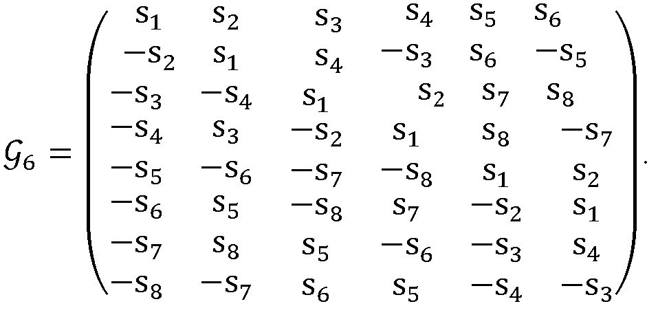
  • G 3 s 1 s 2 s 3 ⁇ s 2 s 1 ⁇ s 4 ⁇ s 3 s 4 s 1 ⁇ s 4 ⁇ s 3 s 2 ;
  • G 6 s 1 s 2 s 3 s 4 s 5 s 6 ⁇ s 2 s 1 s 4 ⁇ s 3 s 6 ⁇ s 5 ⁇ s 3 ⁇ s 4 s 1 s 2 s 7 s 8 ⁇ s 4 s 3 ⁇ s 2 s 1 s 8 ⁇ s 7 ⁇ s 5 ⁇ s 6 ⁇ s 7 ⁇ s 8 s 1 s 2 ⁇ s 6 s 5 ⁇ s 8 s 7 ⁇ s 2 s 1 ⁇ s 6 ⁇ s 3 s 8 s 5 ⁇ s 6 s
  • New space-time block code (New Space-Time Block Code, NSTBC): In recent years, with deep research on backscatter communication, some researchers put forward a concept of backscatter diversity and design a corresponding space-time block code codeword. Based on this type of codeword, hardware implementation complexity is reduced, and a probability of error detection is reduced by optimizing a codebook of conventional Alamouti codes.
  • a symbol transmitted on antenna 1 is denoted as s 1
  • a symbol transmitted on antenna 2 is denoted as s 2 *
  • a symbol transmitted on antenna 1 is denoted as s 2
  • a symbol transmitted on antenna 2 is denoted as ⁇ s 1 * .
  • S 2 belongs to the OSTBC codeword, and therefore can achieve a full diversity gain and full rate transmission. The following analyzes differences between this type of codeword and the conventional Alamouti code in backscatter communication.
  • a coding table for transmitting different symbols simultaneously on two antennas by using a diversity encoding codeword S 2 is Table 4.
  • Table 5 and Table 6 also provide coding tables for transmitting different symbols simultaneously on two antennas by using an Alamouti codeword and an extended Alamouti codeword.
  • the extended Alamouti codeword is: s 1 s 2 s 2 ⁇ ⁇ s 1 ⁇ .
  • Table 4 is a two-antenna transmit diversity coding table of NSTBC space-time block codes
  • Table 5 is a two-antenna transmit diversity coding table of Alamouti space-time block codes
  • Table 6 is an extended two-antenna transmit diversity coding table of Alamouti space-time block codes.
  • antenna 1 requires only two coefficients
  • both antenna 1 and antenna 2 require four coefficients
  • e -j( ⁇ + ⁇ ) that is, four types of load impedances are required on each antenna.
  • the same method may be extended to scenarios with four or more antennas.
  • the full-rate orthogonal codebook can achieve a full rate while achieving a full diversity gain.
  • the full-rate quasi-orthogonal codebook extends the dimensions of the full-rate orthogonal codebook.
  • this type of codebook can extend dimensions to N ⁇ 2 over the field of complex numbers and achieve a diversity gain slightly worse than the full diversity gain.
  • this type of codebook has the following problem: Because orthogonality of the codebook is destroyed, the receive end cannot implement maximum likelihood detection through simple linear processing, processing complexity of the receive end is increased, and communication performance is degraded.
  • the non-full-rate orthogonal codebook ensures orthogonality of the codebook by reducing frequency band utilization or the rate requirement, but the conventional non-full-rate orthogonal codebook is designed for conventional active radio frequency communication, without considering modulation characteristics and implementation complexity of passive terminals similar to backscatter communication terminals.
  • Backscatter communication controls an amplitude or a phase of a signal by changing a load impedance.
  • a modulation circuit for backscatter communication there are more or less errors in an amplitude or a phase of an output signal.
  • these signal errors are within a resolvable range, there is no impact on signal demodulation. Therefore, if there are fewer load impedances to be changed on each antenna, a tolerable error may be greater, and a probability of error detection is lower.
  • none of the conventional full-rate orthogonal codebook, full-rate quasi-orthogonal codebook, and non-full-rate orthogonal codebook take these problems of modulation implementation complexity into account.
  • the non-full-rate orthogonal codebook with N ⁇ 2 codebook dimensions are redesigned by combining the structures of the non-full-rate orthogonal codebook and the NSTBC codebook to extend the dimensions of the orthogonal codebook and reduce modulation implementation complexity.
  • an embodiment of this application provides an encoding method.
  • the method is performed by an encoder.
  • the encoder may be a terminal device or a network-side device.
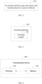
  • the method includes the following step.
  • Step 201 An encoder performs space-time block code encoding on data based on a preset codebook.
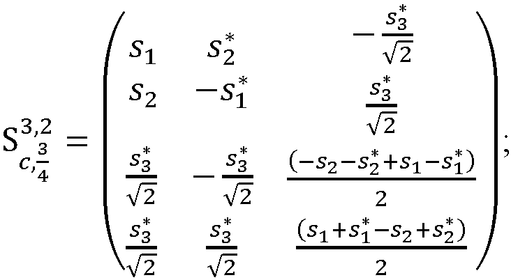
  • the preset codebook is a non-full-rate orthogonal codebook over a field of complex numbers in which an Alamouti (Alamouti) codebook sub-block in the codebook is replaced with a new space-time block code NSTBC codebook sub-block, and columns of the preset codebook are pairwise orthogonal.
  • the performing space-time block code encoding on data may be performing encoding processing on to-be-transmitted original data.
  • the Alamouti codebook sub-block in the non-full-rate orthogonal codebook over the field of complex numbers is replaced with the NSTBC codebook sub-block.
  • the non-full-rate orthogonal codebook over the field of complex numbers by reducing a rate requirement, orthogonality of the codebook is ensured, processing complexity of a receive end is reduced, and degradation of communication performance is avoided.
  • an NSTBC codebook based on an NSTBC codebook, a quantity or types of load impedances on some antennas can be reduced, and a probability of error detection can be effectively reduced, while a diversity gain is ensured.
  • the preset codebook may be referred to as a non-full-rate orthogonal codebook over the field of complex numbers.
  • the non-full-rate orthogonal codebook over the field of complex numbers with low implementation complexity is designed, a codebook structure is redesigned on a basis of a conventional non-full-rate orthogonal codebook over the field of complex numbers, and it is ensured that the columns of the designed codebook are pairwise orthogonal and that a quantity of types of matched impedances corresponding to some antennas is reduced, thereby reducing system implementation complexity and effectively reducing the probability of error detection.
  • N is a quantity of transmit antennas
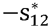
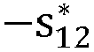
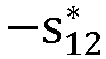
  • s 12 , s 34 , s 34 ⁇ , and ⁇ s 12 ⁇ are all complex numbers
  • s 34 ⁇ is a conjugate complex number of s 34
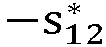
  • ⁇ s 12 ⁇ is an opposite number of a conjugate complex number of s 12 .
  • the Alamouti codebook sub-block in the non-full-rate codebook over the field of complex numbers is replaced with the NSTBC codebook sub-block. Therefore, it is ensured that the designed codebook can reduce the quantity of types of load impedances corresponding to some antennas.
  • the another symbol # over the field of complex numbers in the non-full-rate orthogonal codebook over the field of complex numbers is designed to ensure that the columns of the codebook are pairwise orthogonal, that is, compliant with a construction principle of a generalized orthogonal codebook over the field of complex numbers.
  • the another symbol # over the field of complex numbers in the preset codebook meets: # ⁇ s 1 , s 1 ⁇ , ⁇ s 1 , ⁇ s 1 ⁇ , s 2 , s 2 ⁇ , ⁇ s 2 , ⁇ s 2 ⁇
  • the symbol # cannot be the same as symbols transmitted by antennas 1 and 2 in the first symbol period and the second symbol period, and a conjugate, a negative number, or a negative conjugate of the symbol.
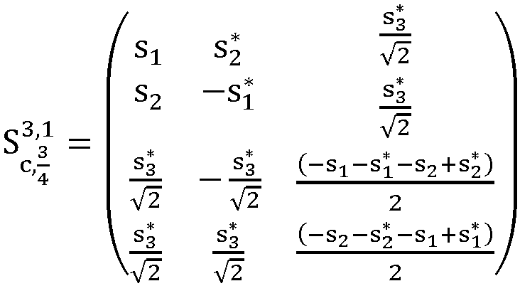
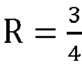
  • a codebook structure of a codebook S c , 3 4 3,1 designed in this solution is redesigned on a basis of a conventional codebook G c , 3 4 3 , that is, in the codebook structure, an Alamouti codebook is replaced with an NSTBC codebook. It is ensured that columns of the designed codebook are pairwise orthogonal and that a quantity of types of matched impedances corresponding to the antennas are reduced.
  • a codebook structure of a codebook S c , 3 4 3,2 designed in this solution is redesigned on a basis of a conventional codebook G c , 3 4 3 , that is, in the codebook structure, an Alamouti codebook is replaced with an NSTBC codebook. It is ensured that columns of the designed codebook are pairwise orthogonal and that a quantity or types of matched impedances corresponding to the antennas are reduced.
  • a codebook structure of a codebook S c , 3 4 3,3 designed in this solution is also redesigned on a basis of a conventional codebook G c , 3 4 3 , that is, in the codebook structure, an Alamouti codebook is replaced with an NSTBC codebook. It is ensured that columns of the designed codebook are pairwise orthogonal and that a quantity or types of matched impedances corresponding to the antennas are reduced.
  • a codebook structure of a codebook S c , 3 4 3,4 designed in this solution is also redesigned on a basis of a conventional codebook G c , 3 4 3 , that is, in the codebook structure, an Alamouti codebook is replaced with an NSTBC codebook. It is ensured that columns of the designed codebook are pairwise orthogonal and that a quantity or types of matched impedances corresponding to the antennas are reduced.
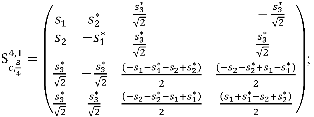
  • a codebook structure of a codebook S c , 3 4 4 ,1 designed in this solution is redesigned on a basis of a conventional codebook G c , 3 4 4 , that is, in the codebook structure, an Alamouti codebook is replaced with an NSTBC codebook. It is ensured that columns of the designed codebook are pairwise orthogonal and that a quantity or types of matched impedances on the antennas are reduced.
  • the columns of the codebook S c , 3 4 4,1 are pairwise orthogonal and compliant with a construction principle of a generalized orthogonal codebook over a field of complex numbers, it is ensured that a receive end can implement a maximum likelihood detection algorithm only by performing simple linear combination processing.
  • a codebook structure of a codebook S c , 3 4 4 ,2 designed in this solution is also redesigned on a basis of a conventional codebook G c , 3 4 4 , that is, in the codebook structure, an Alamouti codebook is replaced with an NSTBC codebook. It is ensured that columns of the designed codebook are pairwise orthogonal and that a quantity or types of matched impedances on the antennas are reduced.
  • the columns of the codebook S c , 3 4 4 ,2 are pairwise orthogonal and compliant with a construction principle of a generalized orthogonal codebook over a field of complex numbers, it is ensured that a receive end can implement a maximum likelihood detection algorithm only by performing simple linear combination processing.
  • the encoding method provided in this embodiment of this application may be performed by an encoding apparatus.
  • An encoding apparatus provided in an embodiment of this application is described by assuming that the encoding apparatus performs the encoding method in this embodiment of this application.
  • an embodiment of this application provides an encoding apparatus, including:
  • the another symbol # over the field of complex numbers in the preset codebook meets: # ⁇ s 1 , s 1 ⁇ , ⁇ s 1 , ⁇ s 1 ⁇ , s 2 , s 2 ⁇ , ⁇ s 2 , ⁇ s 2 ⁇
  • the Alamouti codebook sub-block in the non-full-rate orthogonal codebook over the field of complex numbers is replaced with the NSTBC codebook sub-block.
  • the non-full-rate orthogonal codebook over the field of complex numbers by reducing a rate requirement, orthogonality of the codebook is ensured, processing complexity of a receive end is reduced, and degradation of communication performance is avoided.
  • the NSTBC codebook based on the NSTBC codebook, a quantity or types of load impedances on some antennas can be reduced, and a probability of error detection can be effectively reduced, while a diversity gain is ensured.
  • the encoding apparatus in this embodiment of this application may be an electronic device, for example, an electronic device with an operating system, or may be a component in an electronic device, for example, an integrated circuit or a chip.
  • the electronic device may be a terminal, or may be other devices than a terminal.
  • the terminal may include but is not limited to the foregoing illustrated type of the terminal.
  • the other devices may be a server, a network attached storage (Network Attached Storage, NAS), and the like. This is not specifically limited in this embodiment of this application.
  • the encoding apparatus provided in this embodiment of this application can implement each process implemented in the method embodiment in FIG. 2 , with the same technical effect achieved. To avoid repetition, details are not described herein again.
  • an embodiment of this application further provides a communication device 400, including a processor 401 and a memory 402.
  • the memory 402 stores a program or instructions capable of running on the processor 401.
  • each step of the foregoing embodiment of the encoding method is implemented, with the same technical effect achieved.
  • the communication device 400 is a network-side device, and the program or instructions are executed by the processor 401, each step of the foregoing embodiment of the encoding method is implemented, with the same technical effect achieved. To avoid repetition, details are not described herein again.
  • An embodiment of this application further provides an encoder, including a processor and a communication interface.
  • the processor is configured to perform, by the encoder, space-time block code encoding on data based on a preset codebook, where the preset codebook is a non-full-rate orthogonal codebook over a field of complex numbers in which an Alamouti codebook sub-block in the codebook is replaced with an NSTBC codebook sub-block, and columns of the preset codebook are pairwise orthogonal.
  • FIG. 5 is a schematic diagram of a hardware structure of a terminal for implementing an embodiment of this application.
  • the terminal 500 includes but is not limited to at least some components such as a radio frequency unit 501, a network module 502, an audio output unit 503, an input unit 504, a sensor 505, a display unit 506, a user input unit 507, an interface unit 508, a memory 509, and a processor 510.
  • the terminal 500 may further include a power supply (for example, a battery) supplying power to all components.
  • the power supply may be logically connected to the processor 510 through a power management system. In this way, functions such as charge management, discharge management, and power consumption management are implemented by using the power management system.
  • the terminal structure shown in FIG. 5 does not constitute a limitation on the terminal.
  • the terminal may include more or fewer components than those shown in the figure, or some components are combined, or component arrangements are different. Details are not described herein again.
  • the input unit 504 may include a graphics processing unit (Graphics Processing Unit, GPU) 5041 and a microphone 5042.
  • the graphics processing unit 5041 processes image data of a still picture or video obtained by an image capture apparatus (such as a camera) in a video capture mode or an image capture mode.
  • the display unit 506 may include a display panel 5061, and the display panel 5061 may be configured in a form of a liquid crystal display, an organic light-emitting diode, or the like.
  • the user input unit 507 includes at least one of a touch panel 5071 and other input devices 5072.
  • the touch panel 5071 is also referred to as a touchscreen.
  • the touch panel 5071 may include two parts: a touch detection apparatus and a touch controller.
  • the other input devices 5072 may include but are not limited to a physical keyboard, a function button (such as a volume control button or a power button), a trackball, a mouse, and a joystick. Details are not described herein again.
  • the radio frequency unit 501 may transmit the downlink data to the processor 510 for processing.
  • the radio frequency unit 501 may send uplink data to the network-side device.
  • the radio frequency unit 501 includes but is not limited to an antenna, an amplifier, a transceiver, a coupler, a low noise amplifier, a duplexer, and the like.
  • the memory 509 may be configured to store software programs or instructions and various data.
  • the memory 509 may primarily include a first storage area for storing programs or instructions and a second storage area for storing data.
  • the first storage area may store an operating system, an application program or instructions required by at least one function (such as an audio play function and an image play function), and the like.
  • the memory 509 may include a volatile memory or a non-volatile memory, or the memory 509 may include both a volatile memory and a non-volatile memory.
  • the non-volatile memory may be a read-only memory (Read-Only Memory, ROM), a programmable read-only memory (Programmable ROM, PROM), an erasable programmable read-only memory (Erasable PROM, EPROM), an electrically erasable programmable read-only memory (Electrically EPROM, EEPROM), or a flash memory.
  • ROM Read-Only Memory
  • PROM programmable read-only memory
  • Erasable PROM Erasable PROM
  • EPROM electrically erasable programmable read-only memory
  • EEPROM electrically erasable programmable read-only memory
  • the volatile memory may be a random access memory (Random Access Memory, RAM), a static random access memory (Static RAM, SRAM), a dynamic random access memory (Dynamic RAM, DRAM), a synchronous dynamic random access memory (Synchronous DRAM, SDRAM), a double data rate synchronous dynamic random access memory (Double Data rate SDRAM, DDR SDRAM), an enhanced synchronous dynamic random access memory (Enhanced SDRAM, ESDRAM), a synchlink dynamic random access memory (Synch Link DRAM, SLDRAM), and a direct rambus random access memory (Direct Rambus RAM, DRRAM).
  • RAM Random Access Memory
  • SRAM static random access memory
  • DRAM dynamic random access memory
  • DRAM synchronous dynamic random access memory
  • SDRAM double data rate synchronous dynamic random access memory
  • Enhanced SDRAM, ESDRAM enhanced synchronous dynamic random access memory
  • Synch Link DRAM Synchlink dynamic random access memory
  • SLDRAM direct rambus random access memory
  • Direct Rambus RAM Direct Rambus RAM,
  • the processor 510 may include one or more processing units.
  • the processor 510 integrates an application processor and a modem processor.
  • the application processor mainly processes operations related to the operating system, a user interface, an application program, and the like.
  • the modem processor mainly processes a wireless communication signal.
  • the modem processor is a baseband processor. It may be understood that the modem processor may alternatively be not integrated in the processor 510.
  • the processor 510 is configured to perform, by an encoder, space-time block code encoding on data based on a preset codebook, where the preset codebook is a non-full-rate orthogonal codebook over a field of complex numbers in which an Alamouti codebook sub-block in the codebook is replaced with an NSTBC codebook sub-block, and columns of the preset codebook are pairwise orthogonal.
  • the preset codebook is a non-full-rate orthogonal codebook over a field of complex numbers in which an Alamouti codebook sub-block in the codebook is replaced with an NSTBC codebook sub-block, and columns of the preset codebook are pairwise orthogonal.
  • the Alamouti codebook sub-block in the non-full-rate orthogonal codebook over the field of complex numbers is replaced with the NSTBC codebook sub-block.
  • the non-full-rate orthogonal codebook over the field of complex numbers by reducing a rate requirement, orthogonality of the codebook is ensured, processing complexity of a receive end is reduced, and degradation of communication performance is avoided.
  • an NSTBC codebook based on an NSTBC codebook, a quantity or types of load impedances on some antennas can be reduced, and a probability of error detection can be effectively reduced, while a diversity gain is ensured.
  • the another symbol # over the field of complex numbers in the preset codebook meets: # ⁇ s 1 , s 1 ⁇ , ⁇ s 1 , ⁇ s 1 ⁇ , s 2 , s 2 ⁇ , ⁇ s 2 , ⁇ s 2 ⁇
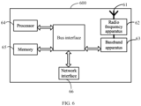
  • the network-side device 600 includes an antenna 61, a radio frequency apparatus 62, a baseband apparatus 63, a processor 64, and a memory 65.
  • the antenna 61 is connected to the radio frequency apparatus 62.
  • the radio frequency apparatus 62 receives information by using the antenna 61, and sends the received information to the baseband apparatus 63 for processing.
  • the baseband apparatus 63 processes to-be-sent information, and sends the information to the radio frequency apparatus 62; and the radio frequency apparatus 62 processes the received information and then sends the information out by using the antenna 61.
  • the method in the foregoing method embodiment may be implemented in the baseband apparatus 63.
  • the baseband apparatus 63 includes a baseband processor.
  • the baseband apparatus 63 may include, for example, at least one baseband unit, where a plurality of chips are disposed on the baseband unit. As shown in FIG. 6 , one of the chips is, for example, the baseband processor, connected to the memory 65 by using a bus interface, to invoke a program in the memory 65 to perform the operation of the network-side device shown in the foregoing method embodiment.
  • the network-side device may further include a network interface 66, where the interface is, for example, a common public radio interface (Common Public Radio Interface, CPRI).
  • CPRI Common Public Radio Interface
  • the network-side device 600 in this embodiment of the present invention further includes a program or instructions stored in the memory 65 and capable of running on the processor 64.
  • the processor 64 invokes the program or instructions in the memory 65, the method performed by each module shown in FIG. 3 is performed, with the same technical effect achieved. To avoid repetition, details are not described herein again.
  • An embodiment of this application further provides a readable storage medium.
  • the readable storage medium stores a program or instructions.
  • the program or instructions are executed by a processor, each process of the foregoing embodiment of the encoding method is implemented, with the same technical effect achieved. To avoid repetition, details are not described herein again.
  • the processor is a processor in the terminal in the foregoing embodiment.
  • the readable storage medium includes a computer-readable storage medium, such as a computer read-only memory ROM, a random access memory RAM, a magnetic disk, or an optical disc.
  • an embodiment of this application provides a chip.
  • the chip includes a processor and a communication interface.
  • the communication interface is coupled to the processor.
  • the processor is configured to run a program or instructions to implement each process of the foregoing embodiment of the encoding method, with the same technical effect achieved. To avoid repetition, details are not described herein again.
  • the chip provided in this embodiment of this application may also be referred to as a system-level chip, a system chip, a chip system, a system-on-chip, or the like.
  • an embodiment of this application provides a computer program product.
  • the computer program product is stored in a storage medium.
  • the computer program product is executed by at least one processor to implement each process of the foregoing embodiment of the encoding method, with the same technical effect achieved. To avoid repetition, details are not described herein again.
  • An embodiment of this application further provides a communication device, configured to perform each process of the foregoing embodiment of the encoding method, with the same technical effect achieved. To avoid repetition, details are not described herein again.
  • the computer software product is stored in a storage medium (such as a ROM/RAM, a magnetic disk, or an optical disc), and includes several instructions for instructing a terminal (which may be a mobile phone, a computer, a server, an air conditioner, a network device, or the like) to perform the methods described in the embodiments of this application.
  • a storage medium such as a ROM/RAM, a magnetic disk, or an optical disc
  • a terminal which may be a mobile phone, a computer, a server, an air conditioner, a network device, or the like

Landscapes

  • Engineering & Computer Science (AREA)
  • Computer Networks & Wireless Communication (AREA)
  • Signal Processing (AREA)
  • Radio Transmission System (AREA)
  • Mobile Radio Communication Systems (AREA)

Abstract

This application pertains to the field of communication technologies, and discloses an encoding method, a device, and a readable storage medium. The method includes: performing, by an encoder, space-time block code encoding on data based on a preset codebook, where the preset codebook is a non-full-rate orthogonal codebook over a field of complex numbers in which an Alamouti codebook sub-block in the codebook is replaced with an NSTBC codebook sub-block, and columns of the preset codebook are pairwise orthogonal.

Description

    CROSS-REFERENCE TO RELATED APPLICATIONS
  • This application claims priority to Chinese Patent Application No. 202210067513.9, filed in China on January 20, 2022 , which is incorporated herein by reference in its entirety.
  • TECHNICAL FIELD
  • This application pertains to the field of communication technologies, and specifically relates to an encoding method, a device, and a readable storage medium.
  • BACKGROUND
  • A full-rate orthogonal codebook can achieve a full rate while achieving a full diversity gain. However, so far, for this type of codebook, a full-rate orthogonal codebook over a field of complex numbers has only N = 2 dimensions, and a full-rate codebook over a field of real numbers has only N = 2, 4, or 8 dimensions. A full-rate quasi-orthogonal codebook extends dimensions of the full-rate orthogonal codebook. In particular, this type of codebook can extend dimensions to N ≥ 2 over the field of complex numbers and achieve a diversity gain slightly worse than the full diversity gain. However, this type of codebook has the following problem: Because orthogonality of the codebook is destroyed, a receive end cannot implement maximum likelihood detection through simple linear processing, processing complexity of the receive end is increased, and communication performance is degraded.
  • A non-full-rate orthogonal codebook ensures orthogonality of the codebook by reducing frequency band utilization or a rate requirement, but the conventional non-full-rate orthogonal codebook is designed for conventional active radio frequency communication, without considering modulation characteristics and implementation complexity of passive terminals similar to backscatter communication terminals.
  • SUMMARY
  • Embodiments of this application provide an encoding method, a device, and a readable storage medium to resolve a problem that orthogonality and applicability to backscatter communication cannot be both considered for an existing codebook when there are N > 2 dimensions.
  • According to a first aspect, an encoding method is provided and includes:
    • performing, by an encoder, space-time block code encoding on data based on a preset codebook, where
    • the preset codebook is a non-full-rate orthogonal codebook over a field of complex numbers in which an Alamouti (Alamouti) codebook sub-block in the codebook is replaced with a new space-time block code (New Space-Time Block Code, NSTBC) codebook sub-block, and columns of the preset codebook are pairwise orthogonal.
  • According to a second aspect, an encoding apparatus is provided and includes:
    • an encoding module, configured to perform, by an encoder, space-time block code encoding on data based on a preset codebook, where
    • the preset codebook is a non-full-rate orthogonal codebook over a field of complex numbers in which an Alamouti codebook sub-block in the codebook is replaced with an NSTBC codebook sub-block, and columns of the preset codebook are pairwise orthogonal.
  • According to a third aspect, an encoder is provided and includes a processor and a communication interface. The processor is configured to perform, by the encoder, space-time block code encoding on data based on a preset codebook, where
    the preset codebook is a non-full-rate orthogonal codebook over a field of complex numbers in which an Alamouti codebook sub-block in the codebook is replaced with an NSTBC codebook sub-block, and columns of the preset codebook are pairwise orthogonal.
  • According to a fourth aspect, a terminal is provided. The terminal includes a processor and a memory. The memory stores a program or instructions capable of running on the processor. When the program or instructions are executed by the processor, the steps of the method according to the first aspect are implemented.
  • According to a fifth aspect, a network-side device is provided. The network-side device includes a processor and a memory. The memory stores a program or instructions capable of running on the processor. When the program or instructions are executed by the processor, the steps of the method according to the first aspect are implemented.
  • According to a sixth aspect, a readable storage medium is provided. The readable storage medium stores a program or instructions. When the program or instructions are executed by a processor, the steps of the method according to the first aspect are implemented.
  • According to a seventh aspect, a chip is provided. The chip includes a processor and a communication interface. The communication interface is coupled to the processor. The processor is configured to run a program or instructions to implement the method according to the first aspect.
  • According to an eighth aspect, a computer program product is provided. The computer program product is stored in a storage medium. The computer program product is executed by at least one processor to implement the steps of the method according to the first aspect.
  • According to a ninth aspect, a communication device is provided and configured to perform the method according to the first aspect.
  • In the embodiments of this application, the Alamouti codebook sub-block in the non-full-rate orthogonal codebook over the field of complex numbers is replaced with the NSTBC codebook sub-block. On one hand, based on the non-full-rate orthogonal codebook over the field of complex numbers, by reducing a rate requirement, orthogonality of the codebook is ensured, processing complexity of a receive end is reduced, and degradation of communication performance is avoided. On the other hand, based on an NSTBC codebook, a quantity or types of load impedances on some antennas can be reduced, and a probability of error detection can be effectively reduced, while a diversity gain is ensured.
  • BRIEF DESCRIPTION OF DRAWINGS
    • FIG. 1a is a schematic diagram of a structure of a backscatter communication transmit end;
    • FIG. 1b is a schematic diagram of Alamouti space-time block code diversity transmission;
    • FIG. 2 is a schematic flowchart of an encoding method according to an embodiment of this application;
    • FIG. 3 is a schematic diagram of a structure of an encoding apparatus according to an embodiment of this application;
    • FIG. 4 is a schematic diagram of a structure of a communication device according to an embodiment of this application;
    • FIG. 5 is a schematic diagram of a structure of a terminal according to an embodiment of this application; and
    • FIG. 6 is a schematic diagram of a structure of a network-side device according to an embodiment of this application.
    DESCRIPTION OF EMBODIMENTS
  • The following clearly describes the technical solutions in the embodiments of this application with reference to the accompanying drawings in the embodiments of this application. Apparently, the described embodiments are only some rather than all of the embodiments of this application. All other embodiments obtained by a person of ordinary skill in the art based on the embodiments of this application shall fall within the protection scope of this application.
  • The terms "first", "second", and the like in this specification and claims of this application are used to distinguish between similar objects instead of describing a specific order or sequence. It should be understood that the terms used in this way are interchangeable in appropriate circumstances, so that the embodiments of this application can be implemented in other orders than the order illustrated or described herein. In addition, objects distinguished by "first" and "second" usually fall within one class, and a quantity of objects is not limited. For example, there may be one or more first objects. In addition, the term "and/or" in the specification and claims indicates at least one of connected objects, and the character "/" generally represents an "or" relationship between associated objects.
  • It should be noted that technologies described in the embodiments of this application are not limited to a long term evolution (Long Term Evolution, LTE)/LTE-Advanced (LTE-Advanced, LTE-A) system, and can also be used in other wireless communication systems, such as code division multiple access (Code Division Multiple Access, CDMA), time division multiple access (Time Division Multiple Access, TDMA), frequency division multiple access (Frequency Division Multiple Access, FDMA), orthogonal frequency division multiple access (Orthogonal Frequency Division Multiple Access, OFDMA), single-carrier frequency-division multiple access (Single-carrier Frequency-Division Multiple Access, SC-FDMA), and other systems. The terms "system" and "network" in the embodiments of this application are usually used interchangeably. The described technologies may be used for the foregoing systems and radio technologies, and may also be used for other systems and radio technologies. However, in the following descriptions, the new radio (New Radio, NR) system is described for an illustrative purpose, and NR terms are used in most of the following descriptions. These technologies may also be applied to other applications than an NR system application, for example, a 6th Generation (6th Generation, 6G) communication system.
  • In the embodiments of this application, an encoder may be deployed on a transmitting device, which may be, for example, a terminal or a network-side device. The terminal may be a terminal-side device such as a mobile phone, a tablet personal computer (Tablet Personal Computer, TPC), a laptop computer (Laptop Computer, LC) or a notebook computer, a personal digital assistant (Personal Digital Assistant, PDA), a palmtop computer, a netbook, an ultra-mobile personal computer (Ultra-Mobile Personal Computer, UMPC), a mobile Internet device (Mobile Internet Device, MID), an augmented reality (Augmented Reality, AR) or virtual reality (Virtual Reality, VR) device, a robot, a wearable device (Wearable Device, WD), vehicle user equipment (Vehicle User Equipment, VUE), pedestrian user equipment (Pedestrian User Equipment, PUE), a smart home (a home device having a wireless communication function, such as a refrigerator, a television, a washing machine, or furniture), a game console, a personal computer (Personal Computer, PC), a teller machine, or a self-service machine. The wearable device includes a smartwatch, a smart band, a smart headphone, smart glasses, smart jewelry (a smart bracelet, a smart wrist chain, a smart ring, a smart necklace, a smart anklet, a smart ankle chain, or the like), a smart wristband, smart clothing, or the like. It should be noted that a specific type of the terminal is not limited in the embodiments of this application. The network-side device may include an access network device or a core network device. The access network device may also be referred to as a radio access network device, a radio access network (Radio Access Network, RAN), a radio access network function, or a radio access network element. The access network device may include a base station, a wireless local area network (Wireless Local Area Network, WLAN) access point, a Wireless Fidelity (Wireless Fidelity, Wi-Fi) node, or the like. The base station may be referred to as a NodeB, an evolved NodeB (eNB), an access point, a base transceiver station (Base Transceiver Station, BTS), a radio base station, a radio transceiver, a basic service set (Basic Service Set, BSS), an extended service set (Extended Service Set, ESS), a home NodeB, a home evolved NodeB, a transmission and reception point (Transmission and Reception Point, TRP), or another appropriate term in the art. As long as the same technical effect is achieved, the base station is not limited to specific technical terms. It should be noted that in the embodiments of this application, only a base station in an NR system is used as an example for description, but a specific type of the base station is not limited. The core network device may include but is not limited to at least one of the following: a core network node, a core network function, a mobility management entity (Mobility Management Entity, MME), an access and mobility management function (Access and Mobility Management Function, AMF), a session management function (Session Management Function, SMF), a user plane function (User Plane Function, UPF), a policy control function (Policy Control Function, PCF), a policy and charging rules function (Policy and Charging Rules Function, PCRF), an edge application server discovery function (Edge Application Server Discovery Function, EASDF), unified data management (Unified Data Management, UDM), a unified data repository (Unified Data Repository, UDR), a home subscriber server (Home Subscriber Server, HSS), a centralized network configuration (Centralized network configuration, CNC), a network repository function (Network Repository Function, NRF), a network exposure function (Network Exposure Function, NEF), a local NEF (Local NEF or L-NEF), a binding support function (Binding Support Function, BSF), an application function (Application Function, AF), or the like. It should be noted that in the embodiments of this application, only a core network device in the NR system is used as an example for description, but a specific type of the core network device is not limited.
  • For better understanding the technical solutions of this application, the following content is first described.
  • A future 6G communication network needs to support the massive Internet of Everything, where a quantity of IoT devices will reach hundreds of billions, and a connection density thereof will be 10-100 times higher than that of 5G, reaching a connection density of 10-100/m2. The massive IoT devices pose new challenges in terms of cost and power consumption. Cellular networking, low cost, low power consumption, and even passive zero power consumption are main trends in development of IoT devices in the future. Conventional passive terminals are limited by power consumption and hardware capabilities of the terminals, and communication transmission distances of most of the terminals are less than 10 meters, far from a goal of cellular coverage of 100 meters. Therefore, how to effectively increase communication distances of passive terminals has become a difficulty that needs to be resolved after cellular networking of this technology.
  • Backscatter communication (Backscatter Communication, BSC):
    Backscatter communication means that a backscatter communication device uses a radio frequency signal from another device or in an environment to perform signal modulation to transmit information of the backscatter communication device. A modulation circuit for backscatter communication is shown in FIG. 1a. The backscatter communication device controls a reflection coefficient Γ of the circuit by adjusting an internal impedance of the backscatter communication device, thereby changing an amplitude, a frequency, a phase, or the like of an incident signal to implement signal modulation. The reflection coefficient of the signal may be represented as: Γ = Z 1 Z 0 Z 1 + Z 0 = Γ e T ,
    Figure imgb0001
    where Z0 is an antenna characteristic impedance, Z1 is a load impedance, j represents a complex number, and θT represents a phase. Assuming that the incident signal is Sin(t), an output signal is Sout(t) = Sin(t) |Γ|eT . Therefore, corresponding amplitude modulation, frequency modulation, or phase modulation can be implemented by properly controlling the reflection coefficient. Based on this, the backscatter communication device may be a tag in a conventional radio frequency identification (Radio Frequency Identification, RFID), or a tag in the passive or semi-passive Internet of Things (Passive/Semi-passive Internet of Things, IoT). For convenience, the foregoing is collectively referred to as BSC user equipment (User Equipment, UE).
  • Full-rate orthogonal space-time block code (Orthogonal Space-Time Block Code, OSTBC):
    Space-time block codes (Space-Time Block Code, STBC) are widely applied in cellular communication and wireless local area networks. By introducing signal redundancy in space domain and time domain and properly constructing a block encoding transmission matrix, the STBC achieves a diversity gain and an antenna gain without increasing a bandwidth.
  • An OSTBC is a special linear STBC, and its linear space-time block code S meets the following single condition: S H S = i = 1 M s i 2 I ,
    Figure imgb0002
    where I represents an identity matrix with M dimensions, i represents an ith element in the M dimensions, si is a diagonal element, an element in an ith row in S represents a symbol transmitted on an ith transmit antenna within M moments, and an element in a jth column in S represents a symbol transmitted at a jth moment on an nt th antenna. In the transmission matrix S, columns that meet the foregoing formula are mutually orthogonal, which means that signal sequences transmitted on different antennas are also orthogonal, thereby ensuring that the STBC can achieve a full diversity gain at the same time. A corresponding decoder only needs to perform simple maximum ratio combining (Maximal ratio combining, MRC) to sequentially decouple transmitted symbols on different antennas, and perform detection and estimation by using a maximum likelihood detection (Maximum likelihood, ML) algorithm.
  • An Alamouti code is a most representative OSTBC code and can achieve a full diversity gain and a full rate gain. FIG. 1b is a principle block diagram of the Alamouti code. In a given symbol period, two symbols are transmitted simultaneously on two antennas. It is assumed that in a current symbol period, a symbol transmitted on antenna 1 is denoted as s1, and that a symbol transmitted on antenna 2 is denoted as s2. In a next symbol period, a symbol transmitted on antenna 1 is s 2 *
    Figure imgb0003
    , and a symbol transmitted on antenna 2 is s 1 *
    Figure imgb0004
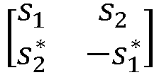
    . In this way, the following space-time block code matrix is formed: S = s 1 s 2 s 2 * s 1 *
    Figure imgb0005
  • Assuming that channels from the two transmit antennas to receive antennas are represented as h1 and h2 respectively and meet time-invariant characteristics in two adjacent symbol periods, that is: h 1 t = h 1 t + T = h 1 = α 1 e 1 ,
    Figure imgb0006
    and h 2 t = h 2 t + T = h 2 = α 2 e 1 ,
    Figure imgb0007
    received signals on the receive antennas in the two symbol periods are: r 1 = r t = h 1 s 1 + h 2 s 2 + n 1 ,
    Figure imgb0008
    and r 2 = r t + T = h 1 s 2 * + h 2 s 1 * + n 2 ,
    Figure imgb0009
    where n1 and n2 represent received noise and signal interference. The decoder performs combined reception according to the following rules: s ^ 1 = h 1 * r 1 + h 2 r 2 * ,
    Figure imgb0010
    and s ^ 2 = h 2 r 1 h 1 r 2
    Figure imgb0011
  • The following may be obtained by substituting the received signals r1 and r2: s ^ 1 = α 1 2 + α 2 2 s 1 + h 1 n 1 + h 2 n 2 ,
    Figure imgb0012
    and s ^ 2 = α 1 2 + α 2 2 s 2 h 1 n 2 + h 2 n 1
    Figure imgb0013
  • Finally, signals s1 and s2 can be estimated by using an ML detector.
  • In addition to the typical Alamouti block code, a codebook of typical two-antenna OSTBCs is shown in Table 1. Table 1
    S -S S* -S*
    s 1 s 2 s 2 s 1
    Figure imgb0014
    s 1 s 2 s 2 s 1
    Figure imgb0015
    s 1 s 2 s 2 s 1
    Figure imgb0016
    s 1 s 2 s 2 s 1
    Figure imgb0017
    s 1 s 2 s 2 s 1
    Figure imgb0018
    s 1 s 2 s 2 s 1
    Figure imgb0019
    s 1 s 2 s 2 s 1
    Figure imgb0020
    s 1 s 2 s 2 s 1
    Figure imgb0021
    s 1 s 2 s 2 s 1
    Figure imgb0022
    s 1 s 2 s 2 s 1
    Figure imgb0023
    s 1 s 2 s 2 s 1
    Figure imgb0024
    s 1 s 2 s 2 s 1
    Figure imgb0025
    s 1 s 2 s 2 s 1
    Figure imgb0026
    s 1 s 2 s 2 s 1
    Figure imgb0027
    s 1 s 2 s 2 s 1
    Figure imgb0028
    s 1 s 2 s 2 s 1
    Figure imgb0029
  • Besides two-dimensional orthogonal space-time block codes over a field of complex numbers, there are also many orthogonal space-time block codes over a field of real numbers, which are not limited by codebook dimensions. Several typical orthogonal space-time block codes over the field of real numbers are as follows: G 4 = s 1 s 2 s 3 s 4 s 2 s 1 s 4 s 3 s 3 s 4 s 1 s 2 s 4 s 3 s 2 s 1 ;
    Figure imgb0030
    and G 8 = s 1 s 2 s 3 s 4 s 5 s 6 s 7 s 8 s 2 s 1 s 4 s 3 s 6 s 5 s 8 s 7 s 3 s 4 s 1 s 2 s 7 s 8 s 5 s 6 s 4 s 3 s 2 s 1 s 8 s 7 s 6 s 5 s 5 s 6 s 7 s 8 s 1 s 2 s 3 s 4 s 6 s 5 s 8 s 7 s 2 s 1 s 4 s 3 s 7 s 8 s 5 s 6 s 3 s 4 s 1 s 2 s 8 s 7 s 6 s 5 s 4 s 3 s 2 s 1
    Figure imgb0031
  • Because an orthogonal codebook ensures that a received signal is only linear superposition of a transmitted signal with noise, a receive end can achieve an effect of maximum likelihood estimation only by simple linear processing. Further, differential space-time block codes also require orthogonality of the codebook. However, unfortunately, up to now, a full-rate orthogonal codebook over the field of complex numbers has only N = 2 dimensions, and a full-rate codebook over the field of real numbers has only N = 2, 4, or 8 dimensions.
  • Full-rate quasi-orthogonal space-time block code (Quasi-Orthogonal Space-Time Block Code, QSTBC):
  • Although the OSTBC can achieve a full diversity gain and full-rate transmission, unfortunately, it has been proved that no OSTBC codebook can achieve both a full diversity gain and a full rate when a quantity of transmit antennas is greater than 2. The quasi-orthogonal space-time block code QSTBC is an extended STBC block code codeword. In this codeword, columns in an encoding matrix may be divided into groups, and column elements in each group are not orthogonal, but orthogonality between different groups is still maintained. More generally, for a codeword matrix S with N × N dimensions, the matrix meets: SS H = i = 1 N s i 2 Q ,
    Figure imgb0032
    where Q is a sparse matrix, a diagonal element of the sparse matrix is 1, and at least N2/2 zero elements are off-diagonal. Therefore, the codeword matrix S that meets the foregoing formula is a QSTBC codebook. Although the QSTBC cannot achieve both a full diversity gain and a full rate, the QSTBC can achieve a diversity gain slightly worse than the full diversity gain and can achieve the full rate.
  • Currently known QSTBCs include an EA-type QSTBC SEA proposed by Jajarkhani, an ABBA-type QSTBC SABBA, a PF-type QSTBC SPF proposed by Papadias and Foschini, and linear transformations of the three types of block code codewords. The following Table 2 and Table 3 show typical four-antenna transmit diversity codebooks. Table 2 shows typical four-antenna transmit diversity QSTBC codebooks. Table 3 shows typical four-antenna transmit diversity QSTBC codebooks after linear transformations. Table 2
    ABBA-type QSTBCs EA-type QSTBCs
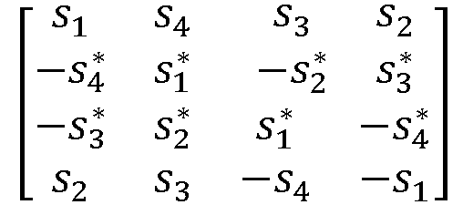
    s 1 s 2 s 3 s 4 s 2 s 1 s 4 s 3 s 3 s 4 s 1 s 2 s 4 s 3 s 2 s 1
    Figure imgb0033
    s 1 s 2 s 4 s 3 s 2 s 1 s 3 s 4 s 4 s 3 s 1 s 2 s 3 s 4 s 2 s 1
    Figure imgb0034
    s 1 s 2 s 3 s 4 s 2 s 1 s 4 s 3 s 3 s 4 s 1 s 2 s 4 s 3 s 2 s 1
    Figure imgb0035
    s 1 s 2 s 4 s 3 s 2 s 1 s 3 s 4 s 4 s 3 s 1 s 2 s 3 s 4 s 2 s 1
    Figure imgb0036
    s 1 s 3 s 2 s 4 s 3 s 1 s 4 s 2 s 2 s 4 s 1 s 3 s 4 s 2 s 3 s 1
    Figure imgb0037
    s 1 s 4 s 3 s 2 s 4 s 1 s 2 s 3 s 3 s 2 s 1 s 4 s 2 s 3 s 4 s 1
    Figure imgb0038
    s 1 s 3 s 2 s 4 s 3 s 1 s 4 s 2 s 2 s 4 s 1 s 3 s 4 s 2 s 3 s 1
    Figure imgb0039
    s 1 s 4 s 3 s 2 s 4 s 1 s 2 s 3 s 3 s 2 s 1 s 4 s 2 s 3 s 4 s 1
    Figure imgb0040
    s 1 s 2 s 4 s 3 s 2 s 1 s 3 s 4 s 4 s 3 s 1 s 2 s 3 s 4 s 2 s 1
    Figure imgb0041
    s 1 s 2 s 3 s 4 s 2 s 1 s 4 s 3 s 3 s 4 s 1 s 2 s 4 s 3 s 2 s 1
    Figure imgb0042
    s 1 s 2 s 4 s 3 s 2 s 1 s 3 s 4 s 4 s 3 s 1 s 2 s 3 s 4 s 2 s 1
    Figure imgb0043
    s 1 s 2 s 3 s 4 s 2 s 1 s 4 s 3 s 3 s 4 s 1 s 2 s 4 s 3 s 2 s 1
    Figure imgb0044
    Table 3
    Linear transformations of ABBA-type QSTBCs Linear transformations of EA-type QSTBCs
    s 1 s 2 s 4 s 3 s 2 s 1 s 3 s 4 s 4 s 3 s 1 s 2 s 3 s 4 s 2 s 1
    Figure imgb0045
    s 1 s 2 s 4 s 3 s 2 s 1 s 3 s 4 s 4 s 3 s 1 s 2 s 3 s 4 s 2 s 1
    Figure imgb0046
    s 1 s 2 s 3 s 4 s 2 s 1 s 4 s 3 s 3 s 4 s 1 s 2 s 4 s 3 s 2 s 1
    Figure imgb0047
    s 1 s 2 s 4 s 3 s 2 s 1 s 3 s 4 s 4 s 3 s 1 s 2 s 3 s 4 s 2 s 1
    Figure imgb0048
    s 1 s 3 s 2 s 4 s 3 s 1 s 4 s 2 s 2 s 4 s 1 s 3 s 4 s 2 s 3 s 1
    Figure imgb0049
    s 1 s 4 s 3 s 2 s 4 s 1 s 2 s 3 s 3 s 2 s 1 s 4 s 2 s 3 s 4 s 1
    Figure imgb0050
    s 1 s 3 s 2 s 4 s 3 s 1 s 4 s 2 s 2 s 4 s 1 s 3 s 4 s 2 s 3 s 1
    Figure imgb0051
    s 1 s 4 s 3 s 2 s 4 s 1 s 2 s 3 s 3 s 2 s 1 s 4 s 2 s 3 s 4 s 1
    Figure imgb0052
    s 1 s 2 s 4 s 3 s 2 s 1 s 3 s 4 s 4 s 3 s 1 s 2 s 4 s 3 s 2 s 1
    Figure imgb0053
    s 1 s 2 s 4 s 3 s 2 s 1 s 3 s 4 s 4 s 3 s 1 s 2 s 3 s 4 s 2 s 1
    Figure imgb0054
    s 1 s 2 s 4 s 3 s 2 s 1 s 3 s 4 s 4 s 3 s 1 s 2 s 4 s 3 s 2 s 1
    Figure imgb0055
    s 1 s 2 s 4 s 3 s 2 s 1 s 3 s 4 s 4 s 3 s 1 s 2 s 3 s 4 s 2 s 1
    Figure imgb0056
  • Non-full-rate orthogonal space-time block code (Non-full-rate Orthogonal Space-Time Block Code):
    Although the full-rate orthogonal codebook over the field of complex numbers has only N = 2 dimensions and the full-rate codebook over the field of real numbers has N = 2, 4, or 8 dimensions, if a full-rate requirement can be reduced, that is, R ≠ 1, there are other orthogonal codebooks regardless of the field of complex numbers or the field of real numbers.
  • The codebook over the field of real numbers is also used as an example. In this case, the dimensions of the codebook may be extended to n = 3, 5, 6, or 7: G 3 = s 1 s 2 s 3 s 2 s 1 s 4 s 3 s 4 s 1 s 4 s 3 s 2 ;
    Figure imgb0057
    and G 6 = s 1 s 2 s 3 s 4 s 5 s 6 s 2 s 1 s 4 s 3 s 6 s 5 s 3 s 4 s 1 s 2 s 7 s 8 s 4 s 3 s 2 s 1 s 8 s 7 s 5 s 6 s 7 s 8 s 1 s 2 s 6 s 5 s 8 s 7 s 2 s 1 s 7 s 8 s 5 s 6 s 3 s 4 s 8 s 7 s 6 s 5 s 4 s 3
    Figure imgb0058
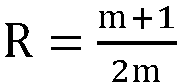
  • Similarly, dimensions of a non-full-rate codebook over the field of complex numbers may also be extended to n ≥ 2 dimensions. In addition, it has been proved theoretically that a maximum rate of a non-full-rate orthogonal codebook is Rmax = m + 1 2m
    Figure imgb0059
    , where a quantity of transmit antennas is n = 2m or n = 2m + 1. Several common codebooks with a rate R = 1 2
    Figure imgb0060
    are as follows: G c , 1 2 3 = s 1 s 2 s 3 s 2 s 1 s 4 s 3 s 4 s 1 s 4 s 3 s 2 s 1 * s 2 * s 3 * s 2 * s 1 * s 4 * s 3 * s 4 * s 1 * s 4 * s 3 * s 2 * ;
    Figure imgb0061
    and G c , 1 2 3 = s 1 s 2 s 3 s 4 s 2 s 1 s 4 s 3 s 3 s 4 s 1 s 2 s 4 s 3 s 2 s 1 s 1 * s 2 * s 3 * s 4 * s 2 * s 1 * s 4 * s 3 * s 3 * s 4 * s 1 * s 2 * s 4 * s 3 * s 2 * s 1 *
    Figure imgb0062
  • Codebooks with a rate R = 3 4
    Figure imgb0063
    are as follows: G c , 3 4 3 = s 1 s 2 s 3 2 s 2 * s 1 * s 3 2 s 3 * 2 s 3 * 2 s 1 s 1 * + s 2 s 2 * 2 s 3 * 2 s 3 * 2 s 2 + s 2 * + s 1 s 1 * 2 ;
    Figure imgb0064
    and G c , 3 4 4 = s 1 s 2 s 3 2 s 3 2 s 2 * s 1 * s 3 2 s 3 2 s 3 * 2 s 3 * 2 s 1 s 1 * + s 2 s 2 * 2 s 2 s 2 * + s 1 s 1 * 2 s 3 * 2 s 3 * 2 s 2 + s 2 * + s 1 s 1 * 2 s 1 + s 1 * + s 2 s 2 * 2
    Figure imgb0065
  • In addition, the non-full-rate orthogonal codebook may also be obtained by zero padding in some space-time positions, as shown below: G c , 3 4 3 = s 3 0 s 2 s 1 0 s 3 s 1 * s 2 * s 2 * s 1 s 3 * 0 s 1 * s 2 0 s 3 *
    Figure imgb0066
  • New space-time block code (New Space-Time Block Code, NSTBC):
    In recent years, with deep research on backscatter communication, some researchers put forward a concept of backscatter diversity and design a corresponding space-time block code codeword. Based on this type of codeword, hardware implementation complexity is reduced, and a probability of error detection is reduced by optimizing a codebook of conventional Alamouti codes.
  • Two-antenna transmit diversity is used as an example, that is, a codeword matrix S in this case has 2 × 2 dimensions, and its coding structure is: S 2 = s 1 s 2 * s 2 s 1 *
    Figure imgb0067
  • According to the foregoing coding structure, it is assumed that in a current symbol period, a symbol transmitted on antenna 1 is denoted as s1, and that a symbol transmitted on antenna 2 is denoted as s 2 *
    Figure imgb0068
    . In a next symbol period, a symbol transmitted on antenna 1 is denoted as s2, and a symbol transmitted on antenna 2 is denoted as s 1 *
    Figure imgb0069
    . According to a definition of an OSTBC codeword, S2 belongs to the OSTBC codeword, and therefore can achieve a full diversity gain and full rate transmission. The following analyzes differences between this type of codeword and the conventional Alamouti code in backscatter communication.
  • Assuming that transmission is performed based on a binary phase shift keying (Binary Phase Shift Keying, BPSK) modulation symbol, according to a backscatter communication mapping principle, mapping rules for symbols 0 and 1 and reflection coefficients are: 0 Γ 1 = Γ e 1 Γ 2 = Γ e j θ + π
    Figure imgb0070
  • In other words, the symbols 0 and 1 are represented by controlling two phase-inverted load impedances. Therefore, a coding table for transmitting different symbols simultaneously on two antennas by using a diversity encoding codeword S2 is Table 4. For comparison, Table 5 and Table 6 also provide coding tables for transmitting different symbols simultaneously on two antennas by using an Alamouti codeword and an extended Alamouti codeword. The extended Alamouti codeword is: s 1 s 2 s 2 s 1
    Figure imgb0071
    . Specifically, Table 4 is a two-antenna transmit diversity coding table of NSTBC space-time block codes, Table 5 is a two-antenna transmit diversity coding table of Alamouti space-time block codes, and Table 6 is an extended two-antenna transmit diversity coding table of Alamouti space-time block codes. Table 4
    00 Antenna 1 Antenna 2 01 Antenna 1 Antenna 2
    t |Γ|e |Γ|e - t |Γ|e |Γ|e -j(θ+π)
    t + T |Γ|e |Γ|e -j(θ+π) t + T |Γ|e j(θ+π) |Γ|e -j(θ+π)
    10 Antenna 1 Antenna 2 11 Antenna 1 Antenna 2
    t |Γ|e j(θ+π) |Γ|e - t |Γ|e j(θ+π) |Γ|e -j(θ+π)
    t + T |Γ|e |Γ|e - t + T |Γ|e j(θ+π) |Γ|e -
    Table 5
    00 Antenna 1 Antenna 2 01 Antenna 1 Antenna 2
    t |Γ|e |Γ|e t |Γ|e |Γ|e j(θ+π)
    t + T |Γ|e -j(θ+π) |Γ|e - t + T |Γ|e - |Γ|e -
    10 Antenna 1 Antenna 2 11 Antenna 1 Antenna 2
    t |Γ|e j(θ+π) |Γ|e t |Γ|e j(θ+π) |Γ|e j(θ+π)
    t + T |Γ|e -j(θ+π) |Γ|e -j(θ+π) t + T |Γ|e - |Γ|e -j(θ+π )
    Table 6
    00 Antenna 1 Antenna 2 01 Antenna 1 Antenna 2
    t |Γ|e |Γ|e t |Γ|e |Γ|e j(θ+π)
    t + T |Γ|e - |Γ|e -j(θ+π) t + T |Γ|e -j(θ+π) |Γ|e -j(θ+π)
    10 Antenna 1 Antenna 2 11 Antenna 1 Antenna 2
    t |Γ|e j(θ+π) |Γ|e t |Γ|e j(θ+π) |Γ|e j(θ+π)
    t + T |Γ|e - |Γ|e - t + T |Γ|e -j(θ+π) |Γ|e -
  • As can be learned according to Table 4, based on the designed codebooks ofNSTBC space-time block codes, antenna 1 requires only two coefficients |Γ|e and |Γ|ej(θ+π); and antenna 2 also requires only two coefficients |Γ|e-jθ and |Γ|e-j(θ+π), that is, only two types of load impedances are required on each antenna. As can be learned according to Table 5 and Table 6, based on the Alamouti codeword and the extended Alamouti codeword, both antenna 1 and antenna 2 require four coefficients |Γ|e, |Γ|ej(θ+π), |Γ|e-jθ, and |Γ|e-j(θ+π), that is, four types of load impedances are required on each antenna. The same method may be extended to scenarios with four or more antennas.
  • The full-rate orthogonal codebook can achieve a full rate while achieving a full diversity gain. However, so far, for this type of codebook, the full-rate orthogonal codebook over the field of complex numbers has only N = 2 dimensions, and the full-rate codebook over the field of real numbers has only N = 2, 4, or 8 dimensions. The full-rate quasi-orthogonal codebook extends the dimensions of the full-rate orthogonal codebook. In particular, this type of codebook can extend dimensions to N ≥ 2 over the field of complex numbers and achieve a diversity gain slightly worse than the full diversity gain. However, this type of codebook has the following problem: Because orthogonality of the codebook is destroyed, the receive end cannot implement maximum likelihood detection through simple linear processing, processing complexity of the receive end is increased, and communication performance is degraded. The non-full-rate orthogonal codebook ensures orthogonality of the codebook by reducing frequency band utilization or the rate requirement, but the conventional non-full-rate orthogonal codebook is designed for conventional active radio frequency communication, without considering modulation characteristics and implementation complexity of passive terminals similar to backscatter communication terminals. Although the novel NSTBC codebook takes modulation characteristics and implementation complexity of passive terminals such as backscatter communication terminals into account, the existing NSTBC codebook has only N = 2 dimensions.
  • Backscatter communication controls an amplitude or a phase of a signal by changing a load impedance. Considering other non-ideal factors in a modulation circuit for backscatter communication, there are more or less errors in an amplitude or a phase of an output signal. However, as long as these signal errors are within a resolvable range, there is no impact on signal demodulation. Therefore, if there are fewer load impedances to be changed on each antenna, a tolerable error may be greater, and a probability of error detection is lower. However, none of the conventional full-rate orthogonal codebook, full-rate quasi-orthogonal codebook, and non-full-rate orthogonal codebook take these problems of modulation implementation complexity into account.
  • Therefore, in the solutions of the present invention, the non-full-rate orthogonal codebook with N ≥ 2 codebook dimensions are redesigned by combining the structures of the non-full-rate orthogonal codebook and the NSTBC codebook to extend the dimensions of the orthogonal codebook and reduce modulation implementation complexity.
  • An encoding method provided in the embodiments of this application is hereinafter described in detail by using some embodiments and application scenarios thereof with reference to the accompanying drawings.
  • Referring to FIG. 2, an embodiment of this application provides an encoding method. The method is performed by an encoder. The encoder may be a terminal device or a network-side device. The method includes the following step.
  • Step 201: An encoder performs space-time block code encoding on data based on a preset codebook.
  • In this embodiment of this application, the preset codebook is a non-full-rate orthogonal codebook over a field of complex numbers in which an Alamouti (Alamouti) codebook sub-block in the codebook is replaced with a new space-time block code NSTBC codebook sub-block, and columns of the preset codebook are pairwise orthogonal.
  • It should be noted that the performing space-time block code encoding on data may be performing encoding processing on to-be-transmitted original data.
  • In this embodiment of this application, the Alamouti codebook sub-block in the non-full-rate orthogonal codebook over the field of complex numbers is replaced with the NSTBC codebook sub-block. On one hand, based on the non-full-rate orthogonal codebook over the field of complex numbers, by reducing a rate requirement, orthogonality of the codebook is ensured, processing complexity of a receive end is reduced, and degradation of communication performance is avoided. On the other hand, based on an NSTBC codebook, a quantity or types of load impedances on some antennas can be reduced, and a probability of error detection can be effectively reduced, while a diversity gain is ensured.
  • Optionally, the preset codebook may be referred to as a non-full-rate orthogonal codebook over the field of complex numbers.
  • In this embodiment of this application, the non-full-rate orthogonal codebook over the field of complex numbers with low implementation complexity is designed, a codebook structure is redesigned on a basis of a conventional non-full-rate orthogonal codebook over the field of complex numbers, and it is ensured that the columns of the designed codebook are pairwise orthogonal and that a quantity of types of matched impedances corresponding to some antennas is reduced, thereby reducing system implementation complexity and effectively reducing the probability of error detection.
  • The following describes characteristics of the constructed non-full-rate orthogonal codebook over the field of complex numbers in this application.
    1. (1) In a specific implementation, a structure of the combined NSTBC codebook is: S = s 12 s 34 s 34 s 12 ,
      Figure imgb0072
      where S is the NSTBC codebook, and elements in S include s12, s34, s 34
      Figure imgb0073
      , and s 12
      Figure imgb0074
      ; s12 is a first basic element, s34 is a second basic element, s 12
      Figure imgb0075
      is a first generation element, and s 34
      Figure imgb0076
      is a second generation element; and s12, s34, s 34
      Figure imgb0077
      , and s 12
      Figure imgb0078
      meet:
      the first generation element is an opposite number of a conjugate operation result of the first basic element, the second generation element is a conjugate operation result of the second basic element, and the first basic element, the second basic element, the first generation element, and the second generation element are complex numbers or block matrices.
  • Specifically, in a case that N is equal to 2, N is a quantity of transmit antennas, s12, s34, s 34
    Figure imgb0079
    , and s 12
    Figure imgb0080
    are all complex numbers, s 34
    Figure imgb0081
    is a conjugate complex number of s34, and s 12
    Figure imgb0082
    is an opposite number of a conjugate complex number of s12.
  • In a specific implementation, a structure of the preset codebook is: S c = s 1 s 2 # s 2 s 1 # # # # ,
    Figure imgb0083
    where Sc is the preset codebook, dimensions of Sc are (p × n), n is a quantity of transmit antennas, p is a symbol period, s1 and s 2
    Figure imgb0084
    are transmitted symbols that are on a first transmit antenna and a second transmit antenna and that are obtained by the encoder through encoding in a first symbol period, s2 and s 1
    Figure imgb0085
    are transmitted symbols that are on the first transmit antenna and the second transmit antenna and that are obtained by the encoder through encoding in a second symbol period, the symbol s 2
    Figure imgb0086
    is a conjugate of the symbol s2, the symbol s 1
    Figure imgb0087
    is a negative conjugate of the symbol s1, and # is another symbol over the field of complex numbers in the preset codebook.
  • In this embodiment of this application, the Alamouti codebook sub-block in the non-full-rate codebook over the field of complex numbers is replaced with the NSTBC codebook sub-block. Therefore, it is ensured that the designed codebook can reduce the quantity of types of load impedances corresponding to some antennas.
  • (2) In a specific implementation, columns Ba and Bb of the preset codebook meet: B a T B b = 0 ;
    Figure imgb0088
    and the preset codebook meets: S c H S c = α × I n × n ,
    Figure imgb0089
    where a and b are integers, 1 ≤ a, b ≤ n, and a ≠ b; and B a T
    Figure imgb0090
    is a transpose of Ba, S c H
    Figure imgb0091
    is a conjugate transpose of Sc, and α is a coefficient factor related to a symbol in the preset codebook. For example, α = a = 1 n B a H B a
    Figure imgb0092
    .
  • In this embodiment of this application, the another symbol # over the field of complex numbers in the non-full-rate orthogonal codebook over the field of complex numbers is designed to ensure that the columns of the codebook are pairwise orthogonal, that is, compliant with a construction principle of a generalized orthogonal codebook over the field of complex numbers.
  • (3) In a specific implementation, the another symbol # over the field of complex numbers in the preset codebook meets: # s 1 , s 1 , s 1 , s 1 , s 2 , s 2 , s 2 , s 2
    Figure imgb0093
  • In this embodiment of this application, the symbol # cannot be the same as symbols transmitted by antennas 1 and 2 in the first symbol period and the second symbol period, and a conjugate, a negative number, or a negative conjugate of the symbol.
  • (4) In a specific implementation, a rate R of the preset codebook meets: R m + 1 2 m ,
    Figure imgb0094
    that is, a maximum rate of the non-full-rate orthogonal codebook over the field of complex numbers may reach R = m + 1 2 m
    Figure imgb0095
    , where
    n = 2m or n = 2m + 1, n is the quantity of transmit antennas, and m is an integer greater than or equal to 1.
  • In this solution, the characteristic (1) of codebook construction ensures that the designed codebook can reduce the quantity of types of matched impedances corresponding to some antennas, thereby reducing hardware implementation complexity and the probability of detection error; the characteristic (2) of codebook construction ensures that the designed codebook is orthogonal, so that the receive end can implement a maximum likelihood detection algorithm only by performing simple linear combination processing; and the characteristic (3) of codebook construction ensures that the maximum rate of the codebook can reach R = m + 1 2 m
    Figure imgb0096
    , where n = 2m or n = 2m + 1, and n is the quantity of transmit antennas.
  • The following describes several specific implementation examples of a non-full-rate orthogonal codebook over a field of complex numbers:
    Example 1: Rate R = 3 4
    Figure imgb0097
    , n = 3, and codebook structure 1. It should be noted that a scenario of R = 3 4
    Figure imgb0098
    and n = 3 is provided herein, where the rate R is less than or equal to a maximum rate.
  • When the rate is R = 3 4
    Figure imgb0099
    , and a quantity n of transmit antennas is equal to 3, a codebook structure of a codebook S c , 3 4 3,1
    Figure imgb0100
    designed in this solution is redesigned on a basis of a conventional codebook G c , 3 4 3
    Figure imgb0101
    , that is, in the codebook structure, an Alamouti codebook is replaced with an NSTBC codebook. It is ensured that columns of the designed codebook are pairwise orthogonal and that a quantity of types of matched impedances corresponding to the antennas are reduced. Because the columns of the codebook S c , 3 4 3,1
    Figure imgb0102
    are pairwise orthogonal and compliant with a construction principle of a generalized orthogonal codebook over a field of complex numbers, it is ensured that a receive end can implement a maximum likelihood detection algorithm only by performing simple linear combination processing. S c , 3 4 3,1 = s 1 s 2 s 3 2 s 2 s 1 s 3 2 s 3 2 s 3 2 s 1 s 1 s 2 + s 2 2 s 3 2 s 3 2 s 2 s 2 s 1 + s 1 2
    Figure imgb0103
  • Example 2: Rate R = 4, n = 3, and codebook structure 2.
  • When the rate is R = 3 4
    Figure imgb0104
    , and a quantity n of transmit antennas is equal to 3, a codebook structure of a codebook S c , 3 4 3,2
    Figure imgb0105
    designed in this solution is redesigned on a basis of a conventional codebook G c , 3 4 3
    Figure imgb0106
    , that is, in the codebook structure, an Alamouti codebook is replaced with an NSTBC codebook. It is ensured that columns of the designed codebook are pairwise orthogonal and that a quantity or types of matched impedances corresponding to the antennas are reduced. Because the columns of the codebook S c , 3 4 3,2
    Figure imgb0107
    are pairwise orthogonal and compliant with a construction principle of a generalized orthogonal codebook over a field of complex numbers, it is ensured that a receive end can implement a maximum likelihood detection algorithm only by performing simple linear combination processing. S c , 3 4 3,2 = s 1 s 2 s 3 2 s 2 s 1 s 3 2 s 3 2 s 3 2 s 2 s 2 + s 1 s 1 2 s 3 2 s 3 2 s 1 + s 1 s 2 + s 2 2
    Figure imgb0108
  • Example 3: Rate R = 4, n = 3, and codebook structure 3.
  • When the rate is R = 3 4
    Figure imgb0109
    , and a quantity n of transmit antennas is equal to 3, a codebook structure of a codebook S c , 3 4 3,3
    Figure imgb0110
    designed in this solution is also redesigned on a basis of a conventional codebook G c , 3 4 3
    Figure imgb0111
    , that is, in the codebook structure, an Alamouti codebook is replaced with an NSTBC codebook. It is ensured that columns of the designed codebook are pairwise orthogonal and that a quantity or types of matched impedances corresponding to the antennas are reduced. Because the columns of the codebook S c , 3 4 3,3
    Figure imgb0112
    are pairwise orthogonal and compliant with a construction principle of a generalized orthogonal codebook over a field of complex numbers, it is ensured that a receive end can implement a maximum likelihood detection algorithm only by performing simple linear combination processing. S c , 3 4 3,3 = s 1 s 2 s 3 2 s 2 s 1 s 3 2 s 3 2 s 3 2 s 1 s 1 + s 2 s 2 2 s 3 2 s 3 2 s 2 s 2 + s 1 s 1 2
    Figure imgb0113
  • Example 4: Rate R = 3 4
    Figure imgb0114
    , n = 3, and codebook structure 4.
  • When the rate is R = 3 4
    Figure imgb0115
    , and a quantity n of transmit antennas is 3, a codebook structure of a codebook S c , 3 4 3,4
    Figure imgb0116
    designed in this solution is also redesigned on a basis of a conventional codebook G c , 3 4 3
    Figure imgb0117
    , that is, in the codebook structure, an Alamouti codebook is replaced with an NSTBC codebook. It is ensured that columns of the designed codebook are pairwise orthogonal and that a quantity or types of matched impedances corresponding to the antennas are reduced. Because the columns of the codebook S c , 3 4 3,4
    Figure imgb0118
    are pairwise orthogonal and compliant with a construction principle of a generalized orthogonal codebook over a field of complex numbers, it is ensured that a receive end can implement a maximum likelihood detection algorithm only by performing simple linear combination processing. S c , 3 4 3,4 = s 1 s 2 s 3 2 s 2 s 1 s 3 2 s 3 2 s 3 2 s 2 s 2 s 1 + s 1 2 s 3 2 s 3 2 s 1 + s 1 + s 2 s 2 2
    Figure imgb0119
  • Example 5: Rate R = 3 4
    Figure imgb0120
    , n = 4, and codebook structure 1.
  • When the rate is R = 3 4
    Figure imgb0121
    , and a quantity n of transmit antennas is 4, a codebook structure of a codebook S c , 3 4 4 ,1
    Figure imgb0122
    designed in this solution is redesigned on a basis of a conventional codebook G c , 3 4 4
    Figure imgb0123
    , that is, in the codebook structure, an Alamouti codebook is replaced with an NSTBC codebook. It is ensured that columns of the designed codebook are pairwise orthogonal and that a quantity or types of matched impedances on the antennas are reduced. Because the columns of the codebook S c , 3 4 4,1
    Figure imgb0124
    are pairwise orthogonal and compliant with a construction principle of a generalized orthogonal codebook over a field of complex numbers, it is ensured that a receive end can implement a maximum likelihood detection algorithm only by performing simple linear combination processing. S c , 3 4 4 ,1 = s 1 s 2 s 3 2 s 3 2 s 2 s 1 s 3 2 s 3 2 s 3 2 s 3 2 s 1 s 1 s 2 + s 2 2 s 2 s 2 + s 1 s 1 2 s 3 2 s 3 2 s 2 s 2 s 1 + s 1 2 s 1 + s 1 s 2 + s 2 2
    Figure imgb0125
  • Example 6: Rate R = 4, n = 4, and codebook structure 2.
  • When the rate is R = 3 4
    Figure imgb0126
    , and a quantity n of transmit antennas is 4, a codebook structure of a codebook S c , 3 4 4 ,2
    Figure imgb0127
    designed in this solution is also redesigned on a basis of a conventional codebook G c , 3 4 4
    Figure imgb0128
    , that is, in the codebook structure, an Alamouti codebook is replaced with an NSTBC codebook. It is ensured that columns of the designed codebook are pairwise orthogonal and that a quantity or types of matched impedances on the antennas are reduced. Because the columns of the codebook S c , 3 4 4 ,2
    Figure imgb0129
    are pairwise orthogonal and compliant with a construction principle of a generalized orthogonal codebook over a field of complex numbers, it is ensured that a receive end can implement a maximum likelihood detection algorithm only by performing simple linear combination processing. S c , 3 4 4 ,2 = s 1 s 2 s 3 2 s 3 2 s 2 s 1 s 3 2 s 3 2 s 3 2 s 3 2 s 1 s 1 + s 2 s 2 2 s 2 s 2 s 1 + s 1 2 s 3 2 s 3 2 s 2 s 2 + s 1 s 1 2 s 1 + s 1 + s 2 s 2 2
    Figure imgb0130
  • The encoding method provided in this embodiment of this application may be performed by an encoding apparatus. An encoding apparatus provided in an embodiment of this application is described by assuming that the encoding apparatus performs the encoding method in this embodiment of this application.
  • Referring to FIG. 3, an embodiment of this application provides an encoding apparatus, including:
    • an encoding module, configured to perform, by an encoder, space-time block code encoding on data based on a preset codebook, where
    • the preset codebook is a non-full-rate orthogonal codebook over a field of complex numbers in which an Alamouti codebook sub-block in the codebook is replaced with an NSTBC codebook sub-block, and columns of the preset codebook are pairwise orthogonal.
  • In a specific implementation, a structure of an NSTBC codebook is: S = s 12 s 34 s 34 s 12 , where
    Figure imgb0131

    S is the NSTBC codebook, and elements in S include s12, s34, s 34
    Figure imgb0132
    , and s 12
    Figure imgb0133
    ; s12 is a first basic element, s34 is a second basic element, s 12
    Figure imgb0134
    is a first generation element, and s 34
    Figure imgb0135
    is a second generation element; and s12, s34, s 34
    Figure imgb0136
    , and s 12
    Figure imgb0137
    meet:
    in a case that N is equal to 2, N is a quantity of transmit antennas, s12, s34, s 34
    Figure imgb0138
    , and s 12
    Figure imgb0139
    are all complex numbers, s 34
    Figure imgb0140
    is a conjugate complex number of s34, and s 12
    Figure imgb0141
    is an opposite number of a conjugate complex number of s12.
  • In a specific implementation, a structure of the preset codebook is: S c = s 1 s 2 # s 2 s 1 # # # # ,
    Figure imgb0142
    where
    Sc is the preset codebook, dimensions of Sc are (p × n), n is a quantity of transmit antennas, p is a symbol period, s1 and s 2
    Figure imgb0143
    are transmitted symbols that are on a first transmit antenna and a second transmit antenna and that are obtained by the encoder through encoding in a first symbol period, s2 and s 1
    Figure imgb0144
    are transmitted symbols that are on the first transmit antenna and the second transmit antenna and that are obtained by the encoder through encoding in a second symbol period, the symbol s 2
    Figure imgb0145
    is a conjugate of the symbol s2, the symbol s 1
    Figure imgb0146
    is a negative conjugate of the symbol s1, and # is another symbol over the field of complex numbers in the preset codebook.
  • In a specific implementation, columns Ba and Bb of the preset codebook meet: B a T B b = 0 ;
    Figure imgb0147
    and the preset codebook meets: S c H S c = α × I n × n ,
    Figure imgb0148
    where a and b are integers, 1 ≤ a, b ≤ n, and a ≠ b; and B a T
    Figure imgb0149
    is a transpose of Ba, S c H
    Figure imgb0150
    is a conjugate transpose of Sc, and α is a coefficient factor related to a symbol in the preset codebook. For example, α = a = 1 n B a H B a
    Figure imgb0151
    .
  • In a specific implementation, the another symbol # over the field of complex numbers in the preset codebook meets: # s 1 , s 1 , s 1 , s 1 , s 2 , s 2 , s 2 , s 2
    Figure imgb0152
  • In a specific implementation, a rate R of the preset codebook meets: R m + 1 2 m ,
    Figure imgb0153
    where n = 2m or n = 2m + 1, n is the quantity of transmit antennas, and m is an integer greater than or equal to 1.
  • In a specific implementation, in a case of R = 3 4
    Figure imgb0154
    and n = 3, the structure of the preset codebook is: S c , 3 4 3,1 = s 1 s 2 s 3 2 s 2 s 1 s 3 2 s 3 2 s 3 2 s 1 s 1 s 2 + s 2 2 s 3 2 s 3 2 s 2 s 2 s 1 + s 1 2 ;
    Figure imgb0155
    or the structure of the preset codebook is: S c , 3 4 3,2 = s 1 s 2 s 3 2 s 2 s 1 s 3 2 s 3 2 s 3 2 s 2 s 2 + s 1 s 1 2 s 3 2 s 3 2 s 1 + s 1 s 2 + s 2 2 ;
    Figure imgb0156
    or the structure of the preset codebook is: S c , 3 4 3,3 = s 1 s 2 s 3 2 s 2 s 1 s 3 2 s 3 2 s 3 2 s 1 s 1 + s 2 s 2 2 s 3 2 s 3 2 s 2 s 2 + s 1 s 1 2 ;
    Figure imgb0157
    or the structure of the preset codebook is: S c , 3 4 3,4 = s 1 s 2 s 3 2 s 2 s 1 s 3 2 s 3 2 s 3 2 s 2 s 2 s 1 + s 1 2 s 3 2 s 3 2 s 1 + s 1 + s 2 s 2 2
    Figure imgb0158
  • In a specific implementation, in a case of R = 3 4
    Figure imgb0159
    and n = 4, the structure of the preset codebook is: S c , 3 4 4,1 = s 1 s 2 s 3 2 s 3 2 s 2 s 1 s 3 2 s 3 2 s 3 2 s 3 2 s 1 s 1 s 2 + s 2 2 s 2 s 2 + s 1 s 1 2 s 3 2 s 3 2 s 2 s 2 s 1 + s 1 2 s 1 + s 1 s 2 + s 2 2 ;
    Figure imgb0160
    or the structure of the preset codebook is: S c , 3 4 4,2 = s 1 s 2 s 3 2 s 3 2 s 2 s 1 s 3 2 s 3 2 s 3 2 s 3 2 s 1 s 1 + s 2 s 2 2 s 2 s 2 s 1 + s 1 2 s 3 2 s 3 2 s 2 s 2 + s 1 s 1 2 s 1 + s 1 + s 2 s 2 2
    Figure imgb0161
  • In this embodiment of this application, the Alamouti codebook sub-block in the non-full-rate orthogonal codebook over the field of complex numbers is replaced with the NSTBC codebook sub-block. On one hand, based on the non-full-rate orthogonal codebook over the field of complex numbers, by reducing a rate requirement, orthogonality of the codebook is ensured, processing complexity of a receive end is reduced, and degradation of communication performance is avoided. On the other hand, based on the NSTBC codebook, a quantity or types of load impedances on some antennas can be reduced, and a probability of error detection can be effectively reduced, while a diversity gain is ensured.
  • The encoding apparatus in this embodiment of this application may be an electronic device, for example, an electronic device with an operating system, or may be a component in an electronic device, for example, an integrated circuit or a chip. The electronic device may be a terminal, or may be other devices than a terminal. For example, the terminal may include but is not limited to the foregoing illustrated type of the terminal. The other devices may be a server, a network attached storage (Network Attached Storage, NAS), and the like. This is not specifically limited in this embodiment of this application.
  • The encoding apparatus provided in this embodiment of this application can implement each process implemented in the method embodiment in FIG. 2, with the same technical effect achieved. To avoid repetition, details are not described herein again.
  • Optionally, as shown in FIG. 4, an embodiment of this application further provides a communication device 400, including a processor 401 and a memory 402. The memory 402 stores a program or instructions capable of running on the processor 401. For example, when the communication device 400 is a terminal, and the program or instructions are executed by the processor 401, each step of the foregoing embodiment of the encoding method is implemented, with the same technical effect achieved. When the communication device 400 is a network-side device, and the program or instructions are executed by the processor 401, each step of the foregoing embodiment of the encoding method is implemented, with the same technical effect achieved. To avoid repetition, details are not described herein again.
  • An embodiment of this application further provides an encoder, including a processor and a communication interface. The processor is configured to perform, by the encoder, space-time block code encoding on data based on a preset codebook, where
    the preset codebook is a non-full-rate orthogonal codebook over a field of complex numbers in which an Alamouti codebook sub-block in the codebook is replaced with an NSTBC codebook sub-block, and columns of the preset codebook are pairwise orthogonal.
  • Specifically, in a case that the encoder is a terminal, FIG. 5 is a schematic diagram of a hardware structure of a terminal for implementing an embodiment of this application.
  • The terminal 500 includes but is not limited to at least some components such as a radio frequency unit 501, a network module 502, an audio output unit 503, an input unit 504, a sensor 505, a display unit 506, a user input unit 507, an interface unit 508, a memory 509, and a processor 510.
  • A person skilled in the art may understand that the terminal 500 may further include a power supply (for example, a battery) supplying power to all components. The power supply may be logically connected to the processor 510 through a power management system. In this way, functions such as charge management, discharge management, and power consumption management are implemented by using the power management system. The terminal structure shown in FIG. 5 does not constitute a limitation on the terminal. The terminal may include more or fewer components than those shown in the figure, or some components are combined, or component arrangements are different. Details are not described herein again.
  • It should be understood that, in this embodiment of this application, the input unit 504 may include a graphics processing unit (Graphics Processing Unit, GPU) 5041 and a microphone 5042. The graphics processing unit 5041 processes image data of a still picture or video obtained by an image capture apparatus (such as a camera) in a video capture mode or an image capture mode. The display unit 506 may include a display panel 5061, and the display panel 5061 may be configured in a form of a liquid crystal display, an organic light-emitting diode, or the like. The user input unit 507 includes at least one of a touch panel 5071 and other input devices 5072. The touch panel 5071 is also referred to as a touchscreen. The touch panel 5071 may include two parts: a touch detection apparatus and a touch controller. The other input devices 5072 may include but are not limited to a physical keyboard, a function button (such as a volume control button or a power button), a trackball, a mouse, and a joystick. Details are not described herein again.
  • In this embodiment of this application, after receiving downlink data from a network-side device, the radio frequency unit 501 may transmit the downlink data to the processor 510 for processing. In addition, the radio frequency unit 501 may send uplink data to the network-side device. Usually, the radio frequency unit 501 includes but is not limited to an antenna, an amplifier, a transceiver, a coupler, a low noise amplifier, a duplexer, and the like.
  • The memory 509 may be configured to store software programs or instructions and various data. The memory 509 may primarily include a first storage area for storing programs or instructions and a second storage area for storing data. The first storage area may store an operating system, an application program or instructions required by at least one function (such as an audio play function and an image play function), and the like. In addition, the memory 509 may include a volatile memory or a non-volatile memory, or the memory 509 may include both a volatile memory and a non-volatile memory. The non-volatile memory may be a read-only memory (Read-Only Memory, ROM), a programmable read-only memory (Programmable ROM, PROM), an erasable programmable read-only memory (Erasable PROM, EPROM), an electrically erasable programmable read-only memory (Electrically EPROM, EEPROM), or a flash memory. The volatile memory may be a random access memory (Random Access Memory, RAM), a static random access memory (Static RAM, SRAM), a dynamic random access memory (Dynamic RAM, DRAM), a synchronous dynamic random access memory (Synchronous DRAM, SDRAM), a double data rate synchronous dynamic random access memory (Double Data rate SDRAM, DDR SDRAM), an enhanced synchronous dynamic random access memory (Enhanced SDRAM, ESDRAM), a synchlink dynamic random access memory (Synch Link DRAM, SLDRAM), and a direct rambus random access memory (Direct Rambus RAM, DRRAM). The memory 509 in this embodiment of this application includes but is not limited to these and any other suitable types of memories.
  • The processor 510 may include one or more processing units. Optionally, the processor 510 integrates an application processor and a modem processor. The application processor mainly processes operations related to the operating system, a user interface, an application program, and the like. The modem processor mainly processes a wireless communication signal. For example, the modem processor is a baseband processor. It may be understood that the modem processor may alternatively be not integrated in the processor 510.
  • The processor 510 is configured to perform, by an encoder, space-time block code encoding on data based on a preset codebook, where
    the preset codebook is a non-full-rate orthogonal codebook over a field of complex numbers in which an Alamouti codebook sub-block in the codebook is replaced with an NSTBC codebook sub-block, and columns of the preset codebook are pairwise orthogonal.
  • In this embodiment of this application, the Alamouti codebook sub-block in the non-full-rate orthogonal codebook over the field of complex numbers is replaced with the NSTBC codebook sub-block. On one hand, based on the non-full-rate orthogonal codebook over the field of complex numbers, by reducing a rate requirement, orthogonality of the codebook is ensured, processing complexity of a receive end is reduced, and degradation of communication performance is avoided. On the other hand, based on an NSTBC codebook, a quantity or types of load impedances on some antennas can be reduced, and a probability of error detection can be effectively reduced, while a diversity gain is ensured.
  • Specifically, a structure of the NSTBC codebook is: S = s 12 s 34 s 34 s 12 ,
    Figure imgb0162
    where S is the NSTBC codebook, and elements in S include s12, s34, s 34
    Figure imgb0163
    , and s 12
    Figure imgb0164
    ; s12 is a first basic element, s34 is a second basic element, s 12
    Figure imgb0165
    is a first generation element, and s 34
    Figure imgb0166
    is a second generation element; and s12, s34, s 34
    Figure imgb0167
    , and s 12
    Figure imgb0168
    meet:
    in a case that N is equal to 2, N is a quantity of transmit antennas, s12, s34, s 34
    Figure imgb0169
    , and s 12
    Figure imgb0170
    are all complex numbers, s 34
    Figure imgb0171
    is a conjugate complex number of s34, and s 12
    Figure imgb0172
    is an opposite number of a conjugate complex number of s12.
  • Specifically, a structure of the preset codebook is: S c = s 1 s 2 # s 2 s 1 # # # # ,
    Figure imgb0173
    where Sc is the preset codebook, dimensions of Sc are (p × n), n is a quantity of transmit antennas, p is a symbol period, s1 and s 2
    Figure imgb0174
    are transmitted symbols that are on a first transmit antenna and a second transmit antenna and that are obtained by the encoder through encoding in a first symbol period, s2 and s 1
    Figure imgb0175
    are transmitted symbols that are on the first transmit antenna and the second transmit antenna and that are obtained by the encoder through encoding in a second symbol period, the symbol s 2
    Figure imgb0176
    is a conjugate of the symbol s2, the symbol s 1
    Figure imgb0177
    is a negative conjugate of the symbol s1, and # is another symbol over the field of complex numbers in the preset codebook.
  • Specifically, columns Ba and Bb of the preset codebook meet: B a T B b = 0 ;
    Figure imgb0178
    and the preset codebook meets: S c H S c = α × I n × n ,
    Figure imgb0179
    where
    a and b are integers, 1 ≤ a, b ≤ n, and a ≠ b; and B a T
    Figure imgb0180
    is a transpose of Ba, S c H
    Figure imgb0181
    is a conjugate transpose of Sc, and α is a coefficient factor related to a symbol in the preset codebook. α = a = 1 n B a H B a
    Figure imgb0182
  • Specifically, the another symbol # over the field of complex numbers in the preset codebook meets: # s 1 , s 1 , s 1 , s 1 , s 2 , s 2 , s 2 , s 2
    Figure imgb0183
  • Specifically, a rate R of the preset codebook meets: R m + 1 2 m ,
    Figure imgb0184
    where n = 2m or n = 2m + 1, n is the quantity of transmit antennas, and m is an integer greater than or equal to 1.
  • Specifically, in a case of R = 3 4
    Figure imgb0185
    and n = 3,
    • the structure of the preset codebook is: S c , 3 4 3,1 = s 1 s 2 s 3 2 s 2 s 1 s 3 2 s 3 2 s 3 2 s 1 s 1 s 2 + s 2 2 s 3 2 s 3 2 s 2 s 2 s 1 + s 1 2 ;
      Figure imgb0186
      or
    • the structure of the preset codebook is: S c , 3 4 3,2 = s 1 s 2 s 3 2 s 2 s 1 s 3 2 s 3 2 s 3 2 s 2 s 2 + s 1 s 1 2 s 3 2 s 3 2 s 1 + s 1 s 2 + s 2 2 ;
      Figure imgb0187
      or
    • the structure of the preset codebook is: S c , 3 4 3,3 = s 1 s 2 s 3 2 s 2 s 1 s 3 2 s 3 2 s 3 2 s 1 s 1 + s 2 s 2 2 s 3 2 s 3 2 s 2 s 2 + s 1 s 1 2 ;
      Figure imgb0188
      or
    • the structure of the preset codebook is: S c , 3 4 3,4 = s 1 s 2 s 3 2 s 2 s 1 s 3 2 s 3 2 s 3 2 s 2 s 2 s 1 + s 1 2 s 3 2 s 3 2 s 1 + s 1 + s 2 s 2 2
      Figure imgb0189
  • Specifically, in a case of R = 3 4
    Figure imgb0190
    and n = 4,
    • the structure of the preset codebook is: S c , 3 4 4,1 = s 1 s 2 s 3 2 s 3 2 s 2 s 1 s 3 2 s 3 2 s 3 2 s 3 2 s 1 s 1 s 2 + s 2 2 s 2 s 2 + s 1 s 1 2 s 3 2 s 3 2 s 2 s 2 s 1 + s 1 2 s 1 + s 1 s 2 + s 2 2 ;
      Figure imgb0191
      or
    • the structure of the preset codebook is: S c , 3 4 4,2 = s 1 s 2 s 3 2 s 3 2 s 2 s 1 s 3 2 s 3 2 s 3 2 s 3 2 s 1 s 1 + s 2 s 2 2 s 2 s 2 s 1 + s 1 2 s 3 2 s 3 2 s 2 s 2 + s 1 s 1 2 s 1 + s 1 + s 2 s 2 2
      Figure imgb0192
  • Specifically, in a case that the encoder is a network-side device, as shown in FIG. 6, the network-side device 600 includes an antenna 61, a radio frequency apparatus 62, a baseband apparatus 63, a processor 64, and a memory 65. The antenna 61 is connected to the radio frequency apparatus 62. In an uplink direction, the radio frequency apparatus 62 receives information by using the antenna 61, and sends the received information to the baseband apparatus 63 for processing. In a downlink direction, the baseband apparatus 63 processes to-be-sent information, and sends the information to the radio frequency apparatus 62; and the radio frequency apparatus 62 processes the received information and then sends the information out by using the antenna 61.
  • The method in the foregoing method embodiment may be implemented in the baseband apparatus 63. The baseband apparatus 63 includes a baseband processor.
  • The baseband apparatus 63 may include, for example, at least one baseband unit, where a plurality of chips are disposed on the baseband unit. As shown in FIG. 6, one of the chips is, for example, the baseband processor, connected to the memory 65 by using a bus interface, to invoke a program in the memory 65 to perform the operation of the network-side device shown in the foregoing method embodiment.
  • The network-side device may further include a network interface 66, where the interface is, for example, a common public radio interface (Common Public Radio Interface, CPRI).
  • Specifically, the network-side device 600 in this embodiment of the present invention further includes a program or instructions stored in the memory 65 and capable of running on the processor 64. When the processor 64 invokes the program or instructions in the memory 65, the method performed by each module shown in FIG. 3 is performed, with the same technical effect achieved. To avoid repetition, details are not described herein again.
  • An embodiment of this application further provides a readable storage medium. The readable storage medium stores a program or instructions. When the program or instructions are executed by a processor, each process of the foregoing embodiment of the encoding method is implemented, with the same technical effect achieved. To avoid repetition, details are not described herein again.
  • The processor is a processor in the terminal in the foregoing embodiment. The readable storage medium includes a computer-readable storage medium, such as a computer read-only memory ROM, a random access memory RAM, a magnetic disk, or an optical disc.
  • In addition, an embodiment of this application provides a chip. The chip includes a processor and a communication interface. The communication interface is coupled to the processor. The processor is configured to run a program or instructions to implement each process of the foregoing embodiment of the encoding method, with the same technical effect achieved. To avoid repetition, details are not described herein again. It should be understood that the chip provided in this embodiment of this application may also be referred to as a system-level chip, a system chip, a chip system, a system-on-chip, or the like.
  • In addition, an embodiment of this application provides a computer program product. The computer program product is stored in a storage medium. The computer program product is executed by at least one processor to implement each process of the foregoing embodiment of the encoding method, with the same technical effect achieved. To avoid repetition, details are not described herein again.
  • An embodiment of this application further provides a communication device, configured to perform each process of the foregoing embodiment of the encoding method, with the same technical effect achieved. To avoid repetition, details are not described herein again.
  • It should be noted that in this specification, the term "comprise", "include", or any of their variants are intended to cover a non-exclusive inclusion, so that a process, a method, an article, or an apparatus that includes a list of elements not only includes those elements but also includes other elements that are not expressly listed, or further includes elements inherent to such process, method, article, or apparatus. In absence of more constraints, an element preceded by "includes a ..." does not preclude existence of other identical elements in the process, method, article, or apparatus that includes the element. In addition, it should be noted that the scope of the method and apparatus in the implementations of this application is not limited to performing the functions in an order shown or discussed, and may further include performing the functions in a substantially simultaneous manner or in a reverse order depending on the functions used. For example, the method described may be performed in an order different from that described, and various steps may be added, omitted, or combined. In addition, features described with reference to some examples may be combined in other examples.
  • According to the foregoing description of the implementations, a person skilled in the art may clearly understand that the methods in the foregoing embodiments may be implemented by using software in combination with a necessary general hardware platform, and certainly may alternatively be implemented by using hardware. However, in most cases, the former is a preferred implementation. Based on such an understanding, the technical solutions of this application essentially or the part contributing to the prior art may be implemented in a form of a computer software product. The computer software product is stored in a storage medium (such as a ROM/RAM, a magnetic disk, or an optical disc), and includes several instructions for instructing a terminal (which may be a mobile phone, a computer, a server, an air conditioner, a network device, or the like) to perform the methods described in the embodiments of this application.
  • The foregoing describes the embodiments of this application with reference to the accompanying drawings. However, this application is not limited to the foregoing specific embodiments. The foregoing specific embodiments are merely illustrative rather than restrictive. Inspired by this application, a person of ordinary skill in the art may develop many other manners without departing from principles of this application and the protection scope of the claims, and all such manners fall within the protection scope of this application.

Claims (22)

  1. An encoding method, comprising:
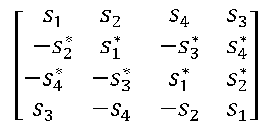
    performing, by an encoder, space-time block code encoding on data based on a preset codebook, wherein
    the preset codebook is a non-full-rate orthogonal codebook over a field of complex numbers in which an Alamouti (Alamouti) codebook sub-block in the codebook is replaced with a new space-time block code NSTBC codebook sub-block, and columns of the preset codebook are pairwise orthogonal.
  2. The method according to claim 1, wherein a structure of an NSTBC codebook is: S = s 12 s 34 s 34 s 12 ,
    Figure imgb0193
    wherein S is the NSTBC codebook, and elements in S comprise s12, s34, s 34
    Figure imgb0194
    , and s 12
    Figure imgb0195
    ; s12 is a first basic element, s34 is a second basic element, s 12
    Figure imgb0196
    is a first generation element, and s 34
    Figure imgb0197
    is a second generation element; and s12, s34, s 34
    Figure imgb0198
    , and s 12
    Figure imgb0199
    meet:
    in a case that N is equal to 2, N is a quantity of transmit antennas, s12, s34, s 34
    Figure imgb0200
    , and s 12
    Figure imgb0201
    are all complex numbers, s 34
    Figure imgb0202
    is a conjugate complex number of s34, and s 12
    Figure imgb0203
    is an opposite number of a conjugate complex number of s12.
  3. The method according to claim 2, wherein a structure of the preset codebook is: S c = s 1 s 2 # s 2 s 1 # # # # ,
    Figure imgb0204
    wherein Sc is the preset codebook, dimensions of Sc are (p × n), n is a quantity of transmit antennas, p is a symbol period, s1 and s 2
    Figure imgb0205
    are transmitted symbols that are on a first transmit antenna and a second transmit antenna and that are obtained by the encoder through encoding in a first symbol period, s2 and s 1
    Figure imgb0206
    are transmitted symbols that are on the first transmit antenna and the second transmit antenna and that are obtained by the encoder through encoding in a second symbol period, the symbol s 2
    Figure imgb0207
    is a conjugate of the symbol s2, the symbol s 1
    Figure imgb0208
    is a negative conjugate of the symbol s1, and # is another symbol over the field of complex numbers in the preset codebook.
  4. The method according to claim 3, wherein columns Ba and Bb of the preset codebook meet: B a T B b = 0 ;
    Figure imgb0209
    and the preset codebook meets: S c H S c = α × I n × n ,
    Figure imgb0210
    wherein a and b are integers, 1 ≤ a, b ≤ n, and a ≠ b; and B a T
    Figure imgb0211
    is a transpose of Ba, S c H
    Figure imgb0212
    is a conjugate transpose of Sc, and α is a coefficient factor related to a symbol in the preset codebook.
  5. The method according to claim 3, wherein the another symbol # over the field of complex numbers in the preset codebook meets: # s 1 , s 1 , s 1 , s 1 , s 2 , s 2 , s 2 , s 2
    Figure imgb0213
  6. The method according to claim 3, wherein a rate R of the preset codebook meets: R m + 1 2 m ,
    Figure imgb0214
    wherein n = 2m or n = 2m + 1, n is the quantity of transmit antennas, and m is an integer greater than or equal to 1.
  7. The method according to claim 6, wherein in a case of R = 3 4
    Figure imgb0215
    and n = 3, the structure of the preset codebook is: S c , 3 4 3,1 = s 1 s 2 s 3 2 s 2 s 1 s 3 2 s 3 2 s 3 2 s 1 s 1 s 2 + s 2 2 s 3 2 s 3 2 s 2 s 2 s 1 + s 1 2 ;
    Figure imgb0216
    or
    the structure of the preset codebook is: S c , 3 4 3,2 = s 1 s 2 s 3 2 s 2 s 1 s 3 2 s 3 2 s 3 2 s 2 s 2 + s 1 s 1 2 s 3 2 s 3 2 s 1 + s 1 s 2 + s 2 2 ;
    Figure imgb0217
    or
    the structure of the preset codebook is: S c , 3 4 3,3 = s 1 s 2 s 3 2 s 2 s 1 s 3 2 s 3 2 s 3 2 s 1 s 1 + s 2 s 2 2 s 3 2 s 3 2 s 2 s 2 + s 1 s 1 2 ;
    Figure imgb0218
    or
    the structure of the preset codebook is: S c , 3 4 3,4 = s 1 s 2 s 3 2 s 2 s 1 s 3 2 s 3 2 s 3 2 s 2 s 2 s 1 + s 1 2 s 3 2 s 3 2 s 1 + s 1 + s 2 s 2 2
    Figure imgb0219
  8. The method according to claim 6, wherein in a case of R = 3 4
    Figure imgb0220
    and n = 4,
    the structure of the preset codebook is: S c , 3 4 4,1 = s 1 s 2 s 3 2 s 3 2 s 2 s 1 s 3 2 s 3 2 s 3 2 s 3 2 s 1 s 1 s 2 + s 2 2 s 2 s 2 + s 1 s 1 2 s 3 2 s 3 2 s 2 s 2 s 1 + s 1 2 s 1 + s 1 s 2 + s 2 2 ;
    Figure imgb0221
    or
    the structure of the preset codebook is: S c , 3 4 4,2 = s 1 s 2 s 3 2 s 3 2 s 2 s 1 s 3 2 s 3 2 s 3 2 s 3 2 s 1 s 1 + s 2 s 2 2 s 2 s 2 s 1 + s 1 2 s 3 2 s 3 2 s 2 s 2 + s 1 s 1 2 s 1 + s 1 + s 2 s 2 2
    Figure imgb0222
  9. An encoding apparatus, comprising:
    an encoding module, configured to perform, by an encoder, space-time block code encoding on data based on a preset codebook, wherein
    the preset codebook is a non-full-rate orthogonal codebook over a field of complex numbers in which an Alamouti codebook sub-block in the codebook is replaced with an NSTBC codebook sub-block, and columns of the preset codebook are pairwise orthogonal.
  10. The apparatus according to claim 9, wherein a structure of an NSTBC codebook is: S = s 12 s 34 s 34 s 12 ,
    Figure imgb0223
    wherein S is the NSTBC codebook, and elements in S comprise s12, s34, s 34
    Figure imgb0224
    , and s 12 *
    Figure imgb0225
    ; s12 is a first basic element, s34 is a second basic element, s 12 *
    Figure imgb0226
    is a first generation element, and s 34 *
    Figure imgb0227
    is a second generation element; and s12, s34, s 34 *
    Figure imgb0228
    , and s 12 *
    Figure imgb0229
    meet:
    in a case that N is equal to 2, N is a quantity of transmit antennas, s12, s34, s 34 *
    Figure imgb0230
    , and s 12
    Figure imgb0231
    are all complex numbers, s 34
    Figure imgb0232
    is a conjugate complex number of s34, and s 12
    Figure imgb0233
    is an opposite number of a conjugate complex number of s12.
  11. The apparatus according to claim 10, wherein a structure of the preset codebook is: S c = s 1 s 2 # s 2 s 1 # # # # ,
    Figure imgb0234
    wherein Sc is the preset codebook, dimensions of Sc are (p × n), n is a quantity of transmit antennas, p is a symbol period, s1 and s 2
    Figure imgb0235
    are transmitted symbols that are on a first transmit antenna and a second transmit antenna and that are obtained by the encoder through encoding in a first symbol period, s2 and s 1
    Figure imgb0236
    are transmitted symbols that are on the first transmit antenna and the second transmit antenna and that are obtained by the encoder through encoding in a second symbol period, the symbol s 2
    Figure imgb0237
    is a conjugate of the symbol s2, the symbol s 1
    Figure imgb0238
    is a negative conjugate of the symbol s1, and # is another symbol over the field of complex numbers in the preset codebook.
  12. The apparatus according to 11, wherein columns Ba and Bb of the preset codebook meet: B a T B b = 0 ;
    Figure imgb0239
    and the preset codebook meets: S c H S c = α × I n × n ,
    Figure imgb0240
    wherein a and b are integers, 1 ≤ a, b ≤ n, and a ≠ b; and B a T
    Figure imgb0241
    is a transpose of Ba, S c H
    Figure imgb0242
    is a conjugate transpose of Sc, and α is a coefficient factor related to a symbol in the preset codebook.
  13. The apparatus according to claim 11, wherein the another symbol # over the field of complex numbers in the preset codebook meets: # s 1 , s 1 , s 1 , s 1 , s 2 , s 2 , s 2 , s 2
    Figure imgb0243
  14. The apparatus according to claim 11, wherein a rate R of the preset codebook meets: R m + 1 2 m ,
    Figure imgb0244
    wherein n = 2m or n = 2m + 1, n is the quantity of transmit antennas, and m is an integer greater than or equal to 1.
  15. The apparatus according to claim 14, wherein in a case of R = 3 4
    Figure imgb0245
    and n = 3, the structure of the preset codebook is: S c , 3 4 3,1 = s 1 s 2 s 3 2 s 2 s 1 s 3 2 s 3 2 s 3 2 s 1 s 1 s 2 + s 2 2 s 3 2 s 3 2 s 2 s 2 s 1 + s 1 2 ;
    Figure imgb0246
    or the structure of the preset codebook is: S c , 3 4 3,2 = s 1 s 2 s 3 2 s 2 s 1 s 3 2 s 3 2 s 3 2 s 2 s 2 + s 1 s 1 2 s 3 2 s 3 2 s 1 + s 1 s 2 + s 2 2 ;
    Figure imgb0247
    or the structure of the preset codebook is: S c , 3 4 3,3 = s 1 s 2 s 3 2 s 2 s 1 s 3 2 s 3 2 s 3 2 s 1 s 1 + s 2 s 2 2 s 3 2 s 3 2 s 2 s 2 + s 1 s 1 2 ;
    Figure imgb0248
    or the structure of the preset codebook is: S c , 3 4 3,4 = s 1 s 2 s 3 2 s 2 s 1 s 3 2 s 3 2 s 3 2 s 2 s 2 s 1 + s 1 2 s 3 2 s 3 2 s 1 + s 1 + s 2 s 2 2
    Figure imgb0249
  16. The apparatus according to claim 14, wherein in a case of R = 3 4
    Figure imgb0250
    and n = 4, the structure of the preset codebook is: S c , 3 4 4,1 = s 1 s 2 * s 3 * 2 s 3 * 2 s 2 s 1 * s 3 * 2 s 3 * 2 s 3 * 2 s 3 * 2 s 1 s 1 * s 2 + s 2 * 2 s 2 s 2 * + s 1 s 1 * 2 s 3 * 2 s 3 * 2 s 2 s 2 * s 1 + s 1 * 2 s 1 + s 1 * s 2 + s 2 * 2 ;
    Figure imgb0251
    or the structure of the preset codebook is: S c , 3 4 4,2 = s 1 s 2 * s 3 2 s 3 2 s 2 s 1 * s 3 2 s 3 2 s 3 * 2 s 3 * 2 s 1 s 1 * + s 2 s 2 * 2 s 2 s 2 * s 1 + s 1 * 2 s 3 * 2 s 3 * 2 s 2 s 2 * + s 1 s 1 * 2 s 1 + s 1 * + s 2 s 2 * 2
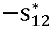
    Figure imgb0252
  17. A terminal, comprising a processor and a memory, wherein the memory stores a program or instructions capable of running on the processor, and when the program or instructions are executed by the processor, the steps of the encoding method according to any one of claims 1 to 8 are implemented.
  18. A network-side device, comprising a processor and a memory, wherein the memory stores a program or instructions capable of running on the processor, and when the program or instructions are executed by the processor, the steps of the encoding method according to any one of claims 1 to 8 are implemented.
  19. A readable storage medium, wherein the readable storage medium stores a program or instructions, and when the program or instructions are executed by a processor, the steps of the encoding method according to any one of claims 1 to 8 are implemented.
  20. A chip, comprising a processor and a communication interface, wherein the communication interface is coupled to the processor, and the processor is configured to run a program or instructions to implement the steps of the encoding method according to any one of claims 1 to 8.
  21. A computer program product, wherein the program product is stored in a non-volatile storage medium, and the program product is executed by at least one processor to implement the steps of the encoding method according to any one of claims 1 to 8.
  22. A communication device, wherein the communication device is configured to perform the steps of the encoding method according to any one of claims 1 to 8.
EP23742838.8A 2022-01-20 2023-01-16 Coding method, device and readable storage medium Pending EP4468617A4 (en)

Applications Claiming Priority (2)

Application Number Priority Date Filing Date Title
CN202210067513.9A CN116527089A (en) 2022-01-20 2022-01-20 Encoding method, apparatus, and readable storage medium
PCT/CN2023/072301 WO2023138523A1 (en) 2022-01-20 2023-01-16 Coding method, device and readable storage medium

Publications (2)

Publication Number Publication Date
EP4468617A1 true EP4468617A1 (en) 2024-11-27
EP4468617A4 EP4468617A4 (en) 2025-05-14

Family

ID=87347802

Family Applications (1)

Application Number Title Priority Date Filing Date
EP23742838.8A Pending EP4468617A4 (en) 2022-01-20 2023-01-16 Coding method, device and readable storage medium

Country Status (5)

Country Link
US (1) US20240388382A1 (en)
EP (1) EP4468617A4 (en)
JP (1) JP7785960B2 (en)
CN (1) CN116527089A (en)
WO (1) WO2023138523A1 (en)

Families Citing this family (3)

* Cited by examiner, † Cited by third party
Publication number Priority date Publication date Assignee Title
CN116418998B (en) * 2021-12-30 2025-09-23 维沃移动通信有限公司 Decoding method, device and readable storage medium
US20240250852A1 (en) * 2023-01-24 2024-07-25 Qualcomm Incorporated Multi-antenna reader channel state information acquisition
CN119449231A (en) * 2023-08-04 2025-02-14 维沃移动通信有限公司 Information sending method, receiving method, device and communication equipment

Family Cites Families (13)

* Cited by examiner, † Cited by third party
Publication number Priority date Publication date Assignee Title
KR100767218B1 (en) 2004-08-17 2007-10-17 삼성전자주식회사 Space-time block encoding apparatus and method for improving coding gain
US8194760B2 (en) * 2006-06-01 2012-06-05 Ntt Docomo, Inc. Method and apparatus for distributed space-time coding in wireless radio networks
CN101141232A (en) * 2007-09-29 2008-03-12 中兴通讯股份有限公司 Signal transmitting method and signal transmitting system in a multiple-input multiple-output system
CN101729215B (en) 2008-10-28 2013-10-02 华为技术有限公司 Space-time/ space-frequency code construction method, transmitting method and device
CN101789814B (en) * 2009-01-22 2014-06-11 中兴通讯股份有限公司南京分公司 Method and device for processing data to be transmitted by adopting space-time coding by combining with precoding
CN102045134B (en) * 2010-11-29 2013-01-23 北京星河亮点技术股份有限公司 Full-rate and full-diversity space-time coding/decoding method
US8995320B2 (en) * 2012-04-16 2015-03-31 Qualcomm Incorporated Systems and methods of using space time block codes
JP2017034294A (en) * 2013-12-13 2017-02-09 シャープ株式会社 Base station device, terminal device, transmission method and reception method
CN108234082B (en) * 2017-11-29 2020-08-04 重庆邮电大学 Space modulation-based full diversity space-time coding method
US11870524B2 (en) * 2018-09-05 2024-01-09 Lg Electronics Inc. Method for reporting channel state information in order for performing antenna array-based beamforming in wireless communication system, and device therefor
WO2020166086A1 (en) * 2019-02-15 2020-08-20 株式会社Nttドコモ User terminal and wireless communication method
WO2021007810A1 (en) * 2019-07-17 2021-01-21 Oppo广东移动通信有限公司 Precoding method and communication device
US11290960B2 (en) * 2020-02-10 2022-03-29 Huawei Technologies Co., Ltd. Method and apparatus for low power transmission using backscattering

Also Published As

Publication number Publication date
JP7785960B2 (en) 2025-12-15
EP4468617A4 (en) 2025-05-14
JP2025502433A (en) 2025-01-24
US20240388382A1 (en) 2024-11-21
CN116527089A (en) 2023-08-01
WO2023138523A1 (en) 2023-07-27

Similar Documents

Publication Publication Date Title
EP4468617A1 (en) Coding method, device and readable storage medium
US10064069B2 (en) Method and apparatus for setting beam in mobile communication system
EP4213452A1 (en) Modulation method and apparatus, communication device, and readable storage medium
EP4270888A2 (en) Communication method and communications apparatus
US20240306236A1 (en) Hybrid Multiple Access Communications Method, Terminal, and Network Side Device
EP4576633A1 (en) Data transmission method and communication apparatus
US12562783B2 (en) Diversity transmission method, terminal, and network-side device
US20260088962A1 (en) Channel state information transmission method and apparatus, terminal, and network-side device
US20240340104A1 (en) Encoding method and apparatus, and readable storage medium
CN117336121A (en) Channel estimation method, device, communication equipment, system and storage medium
US20240372650A1 (en) Coding method and apparatus and readable storage medium
US20250343655A1 (en) Phase tracking reference signal transmission method and apparatus, terminal, and network-side device
EP4459916A1 (en) Decoding method and device and readable storage medium
CN116155328A (en) Uplink transmission method, device, terminal and BSC receiving equipment
EP3723426B1 (en) Communication method and system
CN117979443A (en) Downlink signal selection method, terminal and network side equipment
US20260101343A1 (en) Method and apparatus of uplink transmission
WO2023138459A1 (en) Decoding method, device, and readable storage medium
US20260128783A1 (en) Control methods for receiver antenna selection and interference cancelation and apparatus thereof
WO2024138333A1 (en) Uplink multiplexing method and user equipment
US20250365186A1 (en) Information processing method and apparatus, terminal, and network side device
US20110255395A1 (en) Method for constructing space-time/space-frequency code, and transmitting method and apparatus
WO2025171629A1 (en) Downlink shared channel repetitions for system information block transmissions
US20240224358A1 (en) Multi-link operation method, and apparatus thereof
US20250024527A1 (en) Method for initiating establishment of bsc link, terminal, and network side device

Legal Events

Date Code Title Description
STAA Information on the status of an ep patent application or granted ep patent

Free format text: STATUS: THE INTERNATIONAL PUBLICATION HAS BEEN MADE

PUAI Public reference made under article 153(3) epc to a published international application that has entered the european phase

Free format text: ORIGINAL CODE: 0009012

STAA Information on the status of an ep patent application or granted ep patent

Free format text: STATUS: REQUEST FOR EXAMINATION WAS MADE

17P Request for examination filed

Effective date: 20240724

AK Designated contracting states

Kind code of ref document: A1

Designated state(s): AL AT BE BG CH CY CZ DE DK EE ES FI FR GB GR HR HU IE IS IT LI LT LU LV MC ME MK MT NL NO PL PT RO RS SE SI SK SM TR

DAV Request for validation of the european patent (deleted)
DAX Request for extension of the european patent (deleted)
A4 Supplementary search report drawn up and despatched

Effective date: 20250414

RIC1 Information provided on ipc code assigned before grant

Ipc: H04B 7/0456 20170101AFI20250408BHEP