EP4468606A1 - Temperature-compensated over-current detection system - Google Patents
Temperature-compensated over-current detection system Download PDFInfo
- Publication number
- EP4468606A1 EP4468606A1 EP23305830.4A EP23305830A EP4468606A1 EP 4468606 A1 EP4468606 A1 EP 4468606A1 EP 23305830 A EP23305830 A EP 23305830A EP 4468606 A1 EP4468606 A1 EP 4468606A1
- Authority
- EP
- European Patent Office
- Prior art keywords
- voltage
- current
- mirror
- semiconductor switch
- reference voltage
- Prior art date
- Legal status (The legal status is an assumption and is not a legal conclusion. Google has not performed a legal analysis and makes no representation as to the accuracy of the status listed.)
- Granted
Links
Images


Classifications
-
- H—ELECTRICITY
- H03—ELECTRONIC CIRCUITRY
- H03K—PULSE TECHNIQUE
- H03K17/00—Electronic switching or gating, i.e. not by contact-making and –breaking
- H03K17/08—Modifications for protecting switching circuit against overcurrent or overvoltage
- H03K17/082—Modifications for protecting switching circuit against overcurrent or overvoltage by feedback from the output to the control circuit
-
- H—ELECTRICITY
- H03—ELECTRONIC CIRCUITRY
- H03K—PULSE TECHNIQUE
- H03K17/00—Electronic switching or gating, i.e. not by contact-making and –breaking
- H03K17/18—Modifications for indicating state of switch
-
- H—ELECTRICITY
- H03—ELECTRONIC CIRCUITRY
- H03K—PULSE TECHNIQUE
- H03K2217/00—Indexing scheme related to electronic switching or gating, i.e. not by contact-making or -breaking covered by H03K17/00
- H03K2217/0027—Measuring means of, e.g. currents through or voltages across the switch
Definitions
- This disclosure pertains to the field of the protection of power semiconductor switches such as IGBTs or MOSFETs against over currents and damages caused by such over currents.
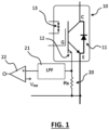
- FIG. 1 shows an example of current measurement device for an IGBT 10 having a current mirror output 12 which gives a current signal proportional to the output current of the IGBT, e.g. 1/100 of the output current of the IGBT.
- the current measurement device comprises a sense resistor Rs, a low pass filter 21 and a comparator 22 having a reference voltage V Ref that corresponds to the current level not to be exceeded in the IGBT.
- Correction circuits are sometimes implemented in such power semiconductor switches or power modules built with such switches.
- correction circuits and temperature sensors add cost and complexity to such power semiconductors and power modules.
- This disclosure improves the situation and in particular addresses the problem to find an alternative method to correct the current sensor sensitivity to the junction temperature Tj.
- a principle used in the present disclosure is to couple the built-in temperature-dependent current sensor and a temperature sensitive element of the die having a similar temperature curve than the current sensor of the semiconductor switch in order to compensate the temperature dependency of the current sensor and obtain a temperature independent overcurrent detection circuit.
- the temperature sensitive element being a gate resistor Rg of said semiconductor switch
- the current source may be connected to said gate resistance Rg of said power semiconductor switch through an emitter or source of said semiconductor switch, in a way that said reference current i R flows during said at least dedicated period of measurement through said gate resistance Rg to provide said reference voltage Ve, said comparator, comparing said reference voltage Ve and said mirror voltage Vs.
- the current source may be configured in parallel with a switch in order to shunt said current source (31) with a command signal line (41) providing a command signal Vsi to inhibit flowing of said reference current i R in said gate resistor outside of said dedicated period of measurement, said dedicated period being made of a pulse within a ON period of the semiconductor switch driven by a driver voltage V driver .
- the measurement resistor Rs may be connected to the low voltage level of the driver voltage source through a capacitor Cs forming a charging circuit provided to generate the mirror voltage Vs with a trapezoidal voltage shape having a positive voltage ramp lower than the gate voltage Vg, said charging circuit comprising a reset switch connected to said charging circuit to discharge said capacitor Cs and connected to said command signal line.
- the temperature sensitive element may be a series of diodes Di located on a die of the semiconductor switch, said current source providing said reference current i R supplying current to said series of diodes Di so that said reference current i R flowing through said series of diodes Di, permanently or during said at least dedicated period of measurement, to provide said reference voltage Vd, amplifying said reference voltage Vd through said amplifier to provide said amplified reference voltage ⁇ Vd comparing said amplified reference voltage ⁇ Vd and said mirror voltage in said comparator.
- the detection circuit may comprise a logic gate receiving a detection signal Ocd and a measurement inhibition signal line providing an inhibition signal to inhibit false detections outside of said dedicated measurement period, said logic gate providing an overcurrent detection logic signal TI-OCD.
- the measurement inhibition signal line may be said command signal line.
- the overcurrent detection circuit may be connected to an overcurrent detection input of said command circuit, said command circuit being configured to switch OFF said semiconductor switch upon occurrence of an overcurrent.
- the signal line may be issued from a switching controller for the power switch.
- the current sensor output i s is a function of the collector current ic and of the junction temperature Tj.
- a and B being two parameter characteristics of the built-in current source for a given sense resistor Rs value.
- Figure 2 shows a semiconductor switch 10 such as an IGBT provided with a first example of an overcurrent detection circuit.
- the IGBT may be replaced by a MOSFET shown on top of the figure where the emitter E of the IGBT being replaced by the source of the MOSFET, the collector of the IGBT being replaced by the drain of the MOSFET and the current mirror output being linked to the source of the MOSFET instead of the emitter of the IGBT.
- the adder providing a mirror voltage Vs mirroring the current Ic flowing through the power switch collector-emitter or drain-source junction.
- the compensation circuit comprises a current source 31 configured to provide a reference current i R , such current source being connected to a temperature sensitive element, which is in this example the gate resistor Rg 14 of the power semiconductor switch, in which said reference current i R flows during at least a dedicated period of measurement as will be seen in correspondence with figure 5A .
- the current i R flowing through the temperature sensitive element 14 in figure 2 provides a reference voltage Ve which is input at a comparator 34 having at its other input the voltage Vs in order to compare said reference voltage Ve and said mirror voltage Vs.
- the compensation circuit is configured to provide at an output of the comparator 34 a detection signal Ocd changing its state when said mirror voltage exceeds said reference voltage Ve.
- the temperature sensitive element being the internal gate resistor Rg 14 of the semiconductor switch
- the current source is connected to such gate resistance Rg 14 through the power emitter E or the Kelvin emitter output in case of the IGBT represented on the drawing or the source of the MOSFET switch such as shown above the IGBT on the drawing, in a way that said reference current i R flows through the gate resistance Rg 14 to provide the reference voltage Ve, which is compared at the comparator 34 with said mirror voltage Vs.
- the measurement period during which the reference current i R is injected in the gate resistance is defined by the switch 37 in parallel with the current source.
- the switch 37 When the switch 37 is open it allows the current i R generated by the current generator 31 to flow in the gate resistance.
- the switch 37 is opened and closed with a command signal line 41 providing a command signal V SI shown in curve 150 in figure 5A . Still in figure 5A , the dedicated period is made with V SI pulse within a ON period of the semiconductor switch driven by a driver voltage V driver as in curve 100.
- the current I R is injected through the gate to emitter of the die. It crosses the internal gate resistor Rg and the input capacitance Ciss. In figure 5A , the result causes a drop 110a in the V GE curve 110 and provides the voltage Ve in curve 120 which comprises the voltage drop across Rg subject to I R and which is sent to the comparator 34.
- the current sensor output i S is shown in curve 130 in solid line for an emitter collector current of the switch under the overcurrent limit and in curve 135 in dotted line for an emitter-collector current above the overcurrent limit. Such current is crossing the sense resistor Rs to provide a voltage V Rs .
- the voltage across Rs is added to the offset voltage V ofst .
- the result of this addition is the voltage Vs in figure 5A , the sensed voltage, which is an image of the sensed current without overcurrent in curve 140 and with overcurrent in curve 145.
- the voltages Ve and Vs are compared in the comparator 34 as shown in figure 5A as Vs-Ve and If Vs is superior to Ve in the detection period as in curve 175, even for small duration, an over-current is detected.
- Such over-current corresponds to the square signal TI-OCD 160 in dotted line in correspondence with the detection period Vsi curve 150. In case no overcurrent exist, the curve Vs-Ve in the detection period remains under zero as in curve 170.
- the previously described circuit allows to monitor the over-current only at specific moments when a current i R is injected through the gate. Before that instant, when there is no current injected, the value at the output of the comparator is positive. It can easily be discarded by a logical AND gate 36 combination. For instance, an over-current is detected if the output of the comparator is high AND the signal in line 41 that controls the injection is high. Other possibilities of logical gates designs are possible depending on the type of logic available.
- Vs ⁇ Ve Rs ⁇ A ⁇ i c + V ofst ⁇ R 0 ⁇ i R + Rs ⁇ B ⁇ Tj ⁇ i c ⁇ ⁇ ⁇ Tj ⁇ i R
- V ofst ⁇ i cMAX ⁇ Rs ⁇ A ⁇ R 0 ⁇ B ⁇
- the crossing point of Vs and Ve occurs at 100A independently of the junction temperature as shown in figure 6 in point 180 on a curve (Vs-Ve) plotted against Ic for different temperatures.
- the sensitivity of the comparison is > 10 mV for 6 A error and increases at high temperature.
- the compensation obtained by the present disclosure design is very good at a specified current and still correct for currents around such specified current.
- Figure 3 shows a second example which is based on the example of figure 2 but in which a capacitor Cs 23 is added between the resistor Rs 20' and the low voltage level of the circuit to generate a trapezoidal voltage shape Vs with a positive voltage ramp but lower than the one of Vg.
- the output of the comparator is high for a longer time. In such case it is necessary to discharge the capacitor Cs and this is done with a further switch 38 which can also be triggered by the V SI signal 41.
- Figure 4 shows another design where the temperature is estimated from small diodes Di 13 built-in the die of the semiconductor switch as in figure 1 .
- a DC current i R is injected through these diodes, the voltage drop is sensitive to the temperature.
- V T V 0 ⁇ ⁇ ⁇ Tj
- Vs + VT Rs ⁇ A ⁇ ic + Vofst + V 0 ⁇ ⁇ + Rs ⁇ B ⁇ Tj ⁇ ic ⁇ ⁇ ⁇ Tj ⁇ ⁇
- the current source is not connected to the IGBT or MOSFET but to the diodes 13 and the voltage Vd at the pins of the diodes is amplified with amplifier 39 and the result ⁇ Vd is compared to the output Vs as in the design of figure 1 .
- Ciss 15 is responsible for the increase of Ve, and the pull-down of the TI-OCD signal. An over-current is thus detected if the signal TI-OCD becomes high, even for a small moment.
- a low-cost component may be advantageously used to latch this signal and increase the robustness and detectability of the detection.
- a too small moment may be filtered by the electronic circuit, and it is necessary to define the value of V ofst such that it triggers at the value of the over-current threshold.
- a calibration method can be used.
- a current pulse with a value i cMAX can be imposed to the die in on-state.
- the length of this pulse is generally short (i.e. less than 1s) to prevent any excessive self-heating.
- the offset voltage V ofst is then increased until the detection of a TI-OCD.
- the corresponding value of V ofst is defined and applied.
- the result of this calibration is mostly dependent on the electronic circuit implementation of the TI-OCD. After being performed once, it can be applied to other circuits, even if used with other power modules.
- i R is less sensitive to the circuit implementation. Prior knowledge of the temperature sensitivity of the built-in current sensor and of the internal gate resistor is required and can be performed easily with conventional measurement set-ups.
- the temperature-dependent over-current can be measured directly across Rs 20, 20', i.e. without the temperature correction or at the output of the adder 33. If an over-current is detected, a temperature-independent over-current estimation can be instantaneously triggered to verify if the detection is an artefact of the temperature or a real over-current detection.
Landscapes
- Measurement Of Current Or Voltage (AREA)
- Electronic Switches (AREA)
- Power Conversion In General (AREA)
Abstract
Description
- This disclosure pertains to the field of the protection of power semiconductor switches such as IGBTs or MOSFETs against over currents and damages caused by such over currents.
- It is known to provide a measurement of the collector-emitter or drain-source current of a power semiconductor switch in order to detect occurrence of an over current.
- Monitoring the current through a power semiconductor switch such as IGBT or MOSFET is important to protect it from over-current or short-circuit (e.g. shoot-through) current. Several means to measure this current can be found in the literature. Monolithic current mirrors built-in the power dies or chips can provide a scaled value of the collector (or drain) current in a compact and reliable way and are implemented in several commercial products.
Figure 1 shows an example of current measurement device for anIGBT 10 having acurrent mirror output 12 which gives a current signal proportional to the output current of the IGBT, e.g. 1/100 of the output current of the IGBT. The current measurement device comprises a sense resistor Rs, alow pass filter 21 and acomparator 22 having a reference voltage VRef that corresponds to the current level not to be exceeded in the IGBT. - One limitation of built-in current sensors such as the
current mirror output 12 is the dependency of the current ratio with the junction temperature Tj, which can reach sensitivities in the order of 1%/K. In the absence of any counter measure, chip temperature margins should be considered in the product design which decrease the ability to finely detect over-current and measure the correct current value. - Correction circuits are sometimes implemented in such power semiconductor switches or power modules built with such switches. However such correction circuits and temperature sensors add cost and complexity to such power semiconductors and power modules.
- This disclosure improves the situation and in particular addresses the problem to find an alternative method to correct the current sensor sensitivity to the junction temperature Tj.
- A principle used in the present disclosure is to couple the built-in temperature-dependent current sensor and a temperature sensitive element of the die having a similar temperature curve than the current sensor of the semiconductor switch in order to compensate the temperature dependency of the current sensor and obtain a temperature independent overcurrent detection circuit.
- More precisely the present disclosure proposes to provide an Overcurrent detection circuit for a semiconductor switch such as an IGBT or a MOSFET said detection circuit comprising a compensation circuit configured to at least partly compensate a temperature dependency of a built-in current mirror output of said power semiconductor switch, said current mirror output being connected to a measurement resistor Rs, connected between said current mirror output and a low voltage level of a driver voltage source to provide a voltage VRs=is·Rs, and connected to a first adder input having a second adder input receiving an offset Vofst to provide a mirror voltage Vs= VRs + Vofst mirroring the current Ic flowing through the power switch emitter-collector or drain-source junction, wherein said compensation circuit comprises a current source configured to provide a reference current iR and connected to a temperature sensitive element of said power semiconductor switch in which said reference current iR flows during at least a dedicated period of measurement through said temperature sensitive element to provide a reference voltage Ve, a comparator, comparing said reference voltage Ve or an amplified reference voltage βVd and said mirror voltage and wherein said compensation circuit is configured to provide at an output of said comparator a detection signal Ocd changing its state when said mirror voltage exceeds said reference voltage Ve or said amplified reference voltage βVd.
- The following features may be optionally implemented, separately or in combination one with the others.
- The temperature sensitive element being a gate resistor Rg of said semiconductor switch, the current source may be connected to said gate resistance Rg of said power semiconductor switch through an emitter or source of said semiconductor switch, in a way that said reference current iR flows during said at least dedicated period of measurement through said gate resistance Rg to provide said reference voltage Ve, said comparator, comparing said reference voltage Ve and said mirror voltage Vs.
- The current source may be configured in parallel with a switch in order to shunt said current source (31) with a command signal line (41) providing a command signal Vsi to inhibit flowing of said reference current iR in said gate resistor outside of said dedicated period of measurement, said dedicated period being made of a pulse within a ON period of the semiconductor switch driven by a driver voltage Vdriver.
- The measurement resistor Rs may be connected to the low voltage level of the driver voltage source through a capacitor Cs forming a charging circuit provided to generate the mirror voltage Vs with a trapezoidal voltage shape having a positive voltage ramp lower than the gate voltage Vg, said charging circuit comprising a reset switch connected to said charging circuit to discharge said capacitor Cs and connected to said command signal line.
- The temperature sensitive element may be a series of diodes Di located on a die of the semiconductor switch, said current source providing said reference current iR supplying current to said series of diodes Di so that said reference current iR flowing through said series of diodes Di, permanently or during said at least dedicated period of measurement, to provide said reference voltage Vd, amplifying said reference voltage Vd through said amplifier to provide said amplified reference voltage βVd comparing said amplified reference voltage βVd and said mirror voltage in said comparator.
- The detection circuit may comprise a logic gate receiving a detection signal Ocd and a measurement inhibition signal line providing an inhibition signal to inhibit false detections outside of said dedicated measurement period, said logic gate providing an overcurrent detection logic signal TI-OCD.
- The measurement inhibition signal line may be said command signal line.
- The overcurrent detection circuit may be connected to an overcurrent detection input of said command circuit, said command circuit being configured to switch OFF said semiconductor switch upon occurrence of an overcurrent.
- The signal line may be issued from a switching controller for the power switch.
- Other features, details and advantages will be shown in the following detailed description and on the figures, on which:
-
Figure 1 is an example of semiconductor power switch with built in current sensor and current measurement circuit; -
Figure 2 is a schematic of a first example of realization of a overcurrent detection circuit according the disclosure; -
Figure 3 is a schematic of a second example of realization of a overcurrent detection circuit according the disclosure; -
Figure 4 is a schematic of a third example of realization of a overcurrent detection circuit according the disclosure; -
Figure 5A is a schematic representation of signals of the first example of realization; -
Figure 5B is a schematic representation of signals of the second example of realization; -
Figure 6 is a resulting curve of the first example of realization. - In a power switch such as in
figure 1 the current sensor output is is a function of the collector current ic and of the junction temperature Tj. For some commercial component, the relation is well expressed by e.g. the following expression:
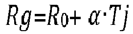
- A and B being two parameter characteristics of the built-in current source for a given sense resistor Rs value. Furthermore, the internal gate resistance of a switch is known to vary e.g. according to:
-
Figure 2 shows asemiconductor switch 10 such as an IGBT provided with a first example of an overcurrent detection circuit. - In this example is shown that the IGBT may be replaced by a MOSFET shown on top of the figure where the emitter E of the IGBT being replaced by the source of the MOSFET, the collector of the IGBT being replaced by the drain of the MOSFET and the current mirror output being linked to the source of the MOSFET instead of the emitter of the IGBT.
- The detection circuit comprises a compensation circuit configured to compensate a temperature dependency of a built-in current mirror of said
power semiconductor switch 10 , saidcurrent mirror output 12 being connected to ameasurement resistor Rs 20, connected between said current mirror output and a low voltage level of adriver voltage source 40 to provide a voltage VRs=is·Rs. - It should be noted that in case of a half-bridge, the schematics of
figure 2 corresponds to an upper branch switch and in case of a lower branch switch the low voltage level would be the lower voltage of the lower branch switch. - The current mirror output and the resistor are connected together to an
adder 33 having a second adder input receiving anoffset V ofst 32, to provide a mirror voltage Vs= VRs + Vofst. - The adder providing a mirror voltage Vs mirroring the current Ic flowing through the power switch collector-emitter or drain-source junction.
- The compensation circuit comprises a
current source 31 configured to provide a reference current iR, such current source being connected to a temperature sensitive element, which is in this example thegate resistor Rg 14 of the power semiconductor switch, in which said reference current iR flows during at least a dedicated period of measurement as will be seen in correspondence withfigure 5A . - The current iR, flowing through the temperature
sensitive element 14 infigure 2 provides a reference voltage Ve which is input at acomparator 34 having at its other input the voltage Vs in order to compare said reference voltage Ve and said mirror voltage Vs. With this configuration, the compensation circuit is configured to provide at an output of the comparator 34 a detection signal Ocd changing its state when said mirror voltage exceeds said reference voltage Ve. - In this example, the temperature sensitive element being the internal
gate resistor Rg 14 of the semiconductor switch, the current source is connected to suchgate resistance Rg 14 through the power emitter E or the Kelvin emitter output in case of the IGBT represented on the drawing or the source of the MOSFET switch such as shown above the IGBT on the drawing, in a way that said reference current iR flows through thegate resistance Rg 14 to provide the reference voltage Ve, which is compared at thecomparator 34 with said mirror voltage Vs. - The measurement period during which the reference current iR is injected in the gate resistance is defined by the
switch 37 in parallel with the current source. When theswitch 37 is open it allows the current iR generated by thecurrent generator 31 to flow in the gate resistance. When theswitch 37 is closed it shunts thecurrent source 31 and stops the current flowing through the resistance outside the measurement period. - The
switch 37 is opened and closed with acommand signal line 41 providing a command signal VSI shown incurve 150 infigure 5A . Still infigure 5A , the dedicated period is made with VSI pulse within a ON period of the semiconductor switch driven by a driver voltage Vdriver as incurve 100. - The current IR is injected through the gate to emitter of the die. It crosses the internal gate resistor Rg and the input capacitance Ciss. In
figure 5A , the result causes a drop 110a in the VGE curve 110 and provides the voltage Ve incurve 120 which comprises the voltage drop across Rg subject to IR and which is sent to thecomparator 34. - The current sensor output iS is shown in
curve 130 in solid line for an emitter collector current of the switch under the overcurrent limit and incurve 135 in dotted line for an emitter-collector current above the overcurrent limit. Such current is crossing the sense resistor Rs to provide a voltage VRs. - The voltage across Rs is added to the offset voltage Vofst. The result of this addition is the voltage Vs in
figure 5A , the sensed voltage, which is an image of the sensed current without overcurrent incurve 140 and with overcurrent incurve 145. - The voltages Ve and Vs are compared in the
comparator 34 as shown infigure 5A as Vs-Ve and If Vs is superior to Ve in the detection period as incurve 175, even for small duration, an over-current is detected. Such over-current corresponds to the square signal TI-OCD 160 in dotted line in correspondence with the detectionperiod Vsi curve 150. In case no overcurrent exist, the curve Vs-Ve in the detection period remains under zero as incurve 170. - The previously described circuit allows to monitor the over-current only at specific moments when a current iR is injected through the gate. Before that instant, when there is no current injected, the value at the output of the comparator is positive. It can easily be discarded by a logical AND
gate 36 combination. For instance, an over-current is detected if the output of the comparator is high AND the signal inline 41 that controls the injection is high. Other possibilities of logical gates designs are possible depending on the type of logic available. - Starting from the formulas above it can be said that:
- At the very beginning instant of the current injection:

- Assuming Vs is complemented by an additional offset voltage, we have :

- To obtain a temperature independency of the over-current threshold ic= icMAX :

- To have Vs - Vg =0 when ic= icMAX:

- Typical values and results are:
A 8.0895e-06 B 1.0195 e-07 Rs 160 Ω R 0 13 Ω α 0.013 Ω/K icMAX 100A ii 125.5 mA Vofst 1.5018 V - With the above numerical values, the crossing point of Vs and Ve occurs at 100A independently of the junction temperature as shown in
figure 6 inpoint 180 on a curve (Vs-Ve) plotted against Ic for different temperatures. In such example, the overcurrent detector is insensitive to the temperature at iC=icMAX=100 A. The sensitivity of the comparison is > 10 mV for 6 A error and increases at high temperature. - As can be seen the compensation obtained by the present disclosure design is very good at a specified current and still correct for currents around such specified current.
-
Figure 3 shows a second example which is based on the example offigure 2 but in which acapacitor Cs 23 is added between the resistor Rs 20' and the low voltage level of the circuit to generate a trapezoidal voltage shape Vs with a positive voltage ramp but lower than the one of Vg. Thus, in case of over-current, the output of the comparator is high for a longer time. In such case it is necessary to discharge the capacitor Cs and this is done with afurther switch 38 which can also be triggered by the VSI signal 41. - The resulting curves are shown in
figure 5B where it can be seen that Vs incurve 140a without overcurrent and 145a with overcurrent being ramped in the detection period causes a higher Vs-Ve curve 175a when the overcurrent is present causing in turn alonger detection 160a in thedetection period Vsi 150. -
Figure 4 shows another design where the temperature is estimated fromsmall diodes Di 13 built-in the die of the semiconductor switch as infigure 1 . When a DC current iR is injected through these diodes, the voltage drop is sensitive to the temperature. - For a constant pre-defined current, the voltage drop across the sensing diode may be expressed as a linear relation with temperature:

- Assuming this voltage drop can be scaled by a parameter β, for example with a voltage divider or a
multiplier circuit 39 using an operational amplifier, the following relation can be obtained:
- To obtain a temperature independency of the over-current threshold:


- In such design, the current source is not connected to the IGBT or MOSFET but to the
diodes 13 and the voltage Vd at the pins of the diodes is amplified withamplifier 39 and the result βVd is compared to the output Vs as in the design offigure 1 . - This design depending on the presence of the diodes Di simplifies the circuit as there is no need to shunt the
current source 31. - Concerning the first and second examples, during the injection, the presence of
Ciss 15 is responsible for the increase of Ve, and the pull-down of the TI-OCD signal. An over-current is thus detected if the signal TI-OCD becomes high, even for a small moment. A low-cost component may be advantageously used to latch this signal and increase the robustness and detectability of the detection. - In practice, a too small moment may be filtered by the electronic circuit, and it is necessary to define the value of Vofst such that it triggers at the value of the over-current threshold. For this, a calibration method can be used. A current pulse with a value icMAX can be imposed to the die in on-state. The length of this pulse is generally short (i.e. less than 1s) to prevent any excessive self-heating. The offset voltage Vofst is then increased until the detection of a TI-OCD. The corresponding value of Vofst is defined and applied. The result of this calibration is mostly dependent on the electronic circuit implementation of the TI-OCD. After being performed once, it can be applied to other circuits, even if used with other power modules.
- Thus, the identification of the parameter Vofst is practical and low-cost.
- The value of i R is less sensitive to the circuit implementation. Prior knowledge of the temperature sensitivity of the built-in current sensor and of the internal gate resistor is required and can be performed easily with conventional measurement set-ups.
- It is sometimes required to continuously monitor the over-current. In this case, the temperature-dependent over-current can be measured directly across
Rs 20, 20', i.e. without the temperature correction or at the output of theadder 33. If an over-current is detected, a temperature-independent over-current estimation can be instantaneously triggered to verify if the detection is an artefact of the temperature or a real over-current detection. - Thus, both a continuous and a temperature over-current detection can be achieved.
- This disclosure is not limited to the examples described here and in example in case other temperature dependent components are present on the semiconductor switch die, such may be used instead of the
diodes 13.
Claims (8)
- Overcurrent detection circuit for a semiconductor switch (10) such as an IGBT or a MOSFET said detection circuit comprising a compensation circuit configured to at least partly compensate a temperature dependency of a built-in current mirror (12) output of said power semiconductor switch (10), said current mirror output (12) being connected to a measurement resistor Rs (20, 20'), connected between said current mirror output and a low voltage level of a driver voltage source (40) to provide a voltage VRs=iS·Rs, and connected to a first adder input having a second adder input receiving an offset Vofst (32) to provide a mirror voltage VS=VRs + Vofst mirroring the current Ic flowing through the power switch emitter-collector or drain-source junction, wherein said compensation circuit comprises a current source (31) configured to provide a reference current iR and connected to a temperature sensitive element (13, 14) of said power semiconductor switch in which said reference current iR flows during at least a dedicated period of measurement through said temperature sensitive element (13, 14) to provide a reference voltage Ve, a comparator (34, 34'), comparing said reference voltage Ve or an amplified reference voltage βVd and said mirror voltage and wherein said compensation circuit is configured to provide at an output of said comparator a detection signal Ocd changing its state when said mirror voltage exceeds said reference voltage Ve or said amplified reference voltage βVd.
- Overcurrent detection circuit as claimed in claim 1 wherein said temperature sensitive element being a gate resistor Rg (14) of said semiconductor switch, said current source is connected to said gate resistance Rg (14) of said power semiconductor switch through an emitter or source of said semiconductor switch, in a way that said reference current iR flows during said at least dedicated period of measurement through said gate resistance Rg (14) to provide said reference voltage Ve, said comparator (34), comparing said reference voltage Ve and said mirror voltage Vs.
- Overcurrent detection circuit as claimed in claim 2 wherein said current source is configured in parallel with a switch in order to shunt said current source (31) with a command signal line (41) providing a command signal Vsi to inhibit flowing of said reference current iR in said gate resistor outside of said dedicated period of measurement, said dedicated period being made of a pulse within a ON period of the semiconductor switch driven by a driver voltage Vdriver.
- Overcurrent detection circuit as claimed in claim 3 wherein the measurement resistor Rs (20') is connected to the low voltage level of the driver voltage source (40) through a capacitor Cs (23) forming a charging circuit provided to generate the mirror voltage Vs with a trapezoidal voltage shape having a positive voltage ramp lower than the gate voltage Vg, said charging circuit comprising a reset switch (38) connected to said charging circuit to discharge said capacitor Cs (23) and connected to said command signal line (41).
- Overcurrent detection circuit as claimed in claim 1 wherein said temperature sensitive element is a series of diodes Di (13) located on a die of the semiconductor switch, said current source (31) providing said reference current iR supplying current to said series of diodes Di (13) said reference current iR flowing through said series of diodes Di (13), permanently or during said at least dedicated period of measurement, to provide said reference voltage Vd, amplifying said reference voltage Vd through said amplifier (39) to provide said amplified reference voltage βVd comparing said amplified reference voltage βVd and said mirror voltage in said comparator (34').
- Overcurrent detection circuit as claimed in any one of claims 1 to 5 comprising a logic gate (36) receiving said detection signal Ocd and a measurement inhibition signal line providing an inhibition signal to inhibit false detections outside of said dedicated measurement period, said logic gate providing an overcurrent detection logic signal TI-OCD.
- Overcurrent detection circuit according to claims 3, 4 or 5 and claim 6 wherein said measurement inhibition signal line is said command signal line (41).
- Command circuit for a semiconductor switch comprising an overcurrent detection circuit as claimed in any one of claims 1 to 7 wherein said overcurrent detection circuit is connected to an overcurrent detection input of said command circuit, said command circuit being configured to switch OFF said semiconductor switch upon occurrence of an overcurrent.
Priority Applications (4)
| Application Number | Priority Date | Filing Date | Title |
|---|---|---|---|
| EP23305830.4A EP4468606B1 (en) | 2023-05-25 | 2023-05-25 | Temperature-compensated over-current detection system |
| PCT/JP2024/080030 WO2024242206A1 (en) | 2023-05-25 | 2024-03-15 | Temperature-compensated over-current detection system |
| JP2025557949A JP2025540503A (en) | 2023-05-25 | 2024-03-15 | Temperature-compensated overcurrent detection system |
| CN202480012840.1A CN121219962A (en) | 2023-05-25 | 2024-03-15 | Temperature-compensated overcurrent detection system |
Applications Claiming Priority (1)
| Application Number | Priority Date | Filing Date | Title |
|---|---|---|---|
| EP23305830.4A EP4468606B1 (en) | 2023-05-25 | 2023-05-25 | Temperature-compensated over-current detection system |
Publications (2)
| Publication Number | Publication Date |
|---|---|
| EP4468606A1 true EP4468606A1 (en) | 2024-11-27 |
| EP4468606B1 EP4468606B1 (en) | 2026-03-18 |
Family
ID=86688734
Family Applications (1)
| Application Number | Title | Priority Date | Filing Date |
|---|---|---|---|
| EP23305830.4A Active EP4468606B1 (en) | 2023-05-25 | 2023-05-25 | Temperature-compensated over-current detection system |
Country Status (4)
| Country | Link |
|---|---|
| EP (1) | EP4468606B1 (en) |
| JP (1) | JP2025540503A (en) |
| CN (1) | CN121219962A (en) |
| WO (1) | WO2024242206A1 (en) |
Families Citing this family (1)
| Publication number | Priority date | Publication date | Assignee | Title |
|---|---|---|---|---|
| CN120671414B (en) * | 2025-08-22 | 2025-12-12 | 国网浙江省电力有限公司舟山供电公司 | A Real-Time Decoupling Modeling Method and System for IGBT Junction Temperature Based on Dynamic Electrothermal Compensation |
Citations (2)
| Publication number | Priority date | Publication date | Assignee | Title |
|---|---|---|---|---|
| US20120224288A1 (en) * | 2011-03-04 | 2012-09-06 | Mitsubishi Electric Corporation | Power module |
| US20180281600A1 (en) * | 2017-03-29 | 2018-10-04 | Ford Global Technologies, Llc | Gate driver with temperature compensated turn-off |
-
2023
- 2023-05-25 EP EP23305830.4A patent/EP4468606B1/en active Active
-
2024
- 2024-03-15 WO PCT/JP2024/080030 patent/WO2024242206A1/en not_active Ceased
- 2024-03-15 CN CN202480012840.1A patent/CN121219962A/en active Pending
- 2024-03-15 JP JP2025557949A patent/JP2025540503A/en active Pending
Patent Citations (2)
| Publication number | Priority date | Publication date | Assignee | Title |
|---|---|---|---|---|
| US20120224288A1 (en) * | 2011-03-04 | 2012-09-06 | Mitsubishi Electric Corporation | Power module |
| US20180281600A1 (en) * | 2017-03-29 | 2018-10-04 | Ford Global Technologies, Llc | Gate driver with temperature compensated turn-off |
Also Published As
| Publication number | Publication date |
|---|---|
| EP4468606B1 (en) | 2026-03-18 |
| JP2025540503A (en) | 2025-12-11 |
| CN121219962A (en) | 2025-12-26 |
| WO2024242206A1 (en) | 2024-11-28 |
Similar Documents
| Publication | Publication Date | Title |
|---|---|---|
| US9683898B2 (en) | Method and apparatus for determining an actual junction temperature of an IGBT device | |
| US5159516A (en) | Overcurrent-detection circuit | |
| US6788128B2 (en) | Overcurrent protection structure of load driving circuit | |
| US7602595B2 (en) | Semiconductor device | |
| US9436193B2 (en) | Electric system comprising a load driving apparatus by auto-recovery mode, and method of operating the apparatus | |
| EP4209791B1 (en) | In situ threshold voltage determination of a semiconductor device | |
| EP4468606B1 (en) | Temperature-compensated over-current detection system | |
| US12278621B2 (en) | Short circuit detection and protection for an insulated gate component by monitoring and checking the gate voltage | |
| DE102023132095A1 (en) | TECHNIQUES FOR MEASURING A VOLTAGE ACROSS A CIRCUIT BREAKER USING A ZERO CURRENT DETECTION POINT | |
| US12405318B2 (en) | Method and apparatus for fast short circuit detection of a short circuit at a gate-controlled power switch | |
| WO2001063765A1 (en) | Power module | |
| US7193410B2 (en) | Transistor monitor for a multiphase circuit | |
| Xie et al. | A Short-Circuit Protection Method for SiC MOSFET Using Combined V gs & V ds Detection | |
| Herwig et al. | Impact of parasitics in power modules and gate drivers on TSEP-based temperature estimations | |
| US10333452B2 (en) | Control apparatus and method for sensing overcurrent of DC motor of vehicle | |
| US12135343B2 (en) | Abnormal current monitoring device and abnormal current monitoring method | |
| JP2002208847A (en) | Gate drive circuit for power semiconductor device | |
| Rafiq et al. | PCB Coil Based Turn-On Delay Measurement For Junction Temperature Estimation of SiC MOSFETs | |
| JPH11340459A (en) | Temperature detecting circuit | |
| US20260058647A1 (en) | Transistor module, driver for transistor module, corresponding system and method | |
| Oiu et al. | Ultrafast Noise-Immune Short-Circuit Detection in Gallium Nitride Power Semiconductors via Drain-Source Voltage Pattern Recognition | |
| Liang et al. | Bond Wire Lift-off Sensor Circuit for Power Devices Integrated in Gate Driver IC | |
| Wang et al. | An Integrated Gate Driver Solution for Silicon Carbide Semiconductor Applications | |
| Krishnappa et al. | Comparison of Short-Circuit Detection and Protection Methods for Silicon Carbide MOSFETs in EV Applications | |
| SU1676085A1 (en) | Power transistors protective device at breakback parameters control |
Legal Events
| Date | Code | Title | Description |
|---|---|---|---|
| PUAI | Public reference made under article 153(3) epc to a published international application that has entered the european phase |
Free format text: ORIGINAL CODE: 0009012 |
|
| STAA | Information on the status of an ep patent application or granted ep patent |
Free format text: STATUS: THE APPLICATION HAS BEEN PUBLISHED |
|
| AK | Designated contracting states |
Kind code of ref document: A1 Designated state(s): AL AT BE BG CH CY CZ DE DK EE ES FI FR GB GR HR HU IE IS IT LI LT LU LV MC ME MK MT NL NO PL PT RO RS SE SI SK SM TR |
|
| STAA | Information on the status of an ep patent application or granted ep patent |
Free format text: STATUS: REQUEST FOR EXAMINATION WAS MADE |
|
| 17P | Request for examination filed |
Effective date: 20250507 |
|
| GRAP | Despatch of communication of intention to grant a patent |
Free format text: ORIGINAL CODE: EPIDOSNIGR1 |
|
| STAA | Information on the status of an ep patent application or granted ep patent |
Free format text: STATUS: GRANT OF PATENT IS INTENDED |
|
| INTG | Intention to grant announced |
Effective date: 20260105 |
|
| GRAS | Grant fee paid |
Free format text: ORIGINAL CODE: EPIDOSNIGR3 |
|
| GRAA | (expected) grant |
Free format text: ORIGINAL CODE: 0009210 |
|
| STAA | Information on the status of an ep patent application or granted ep patent |
Free format text: STATUS: THE PATENT HAS BEEN GRANTED |
|
| P01 | Opt-out of the competence of the unified patent court (upc) registered |
Free format text: CASE NUMBER: UPC_APP_0000742_4468606/2026 Effective date: 20260109 |
|
| AK | Designated contracting states |
Kind code of ref document: B1 Designated state(s): AL AT BE BG CH CY CZ DE DK EE ES FI FR GB GR HR HU IE IS IT LI LT LU LV MC ME MK MT NL NO PL PT RO RS SE SI SK SM TR |
|
| REG | Reference to a national code |
Ref country code: CH Ref legal event code: F10 Free format text: ST27 STATUS EVENT CODE: U-0-0-F10-F00 (AS PROVIDED BY THE NATIONAL OFFICE) Effective date: 20260318 Ref country code: GB Ref legal event code: FG4D |
|
| REG | Reference to a national code |
Ref country code: IE Ref legal event code: FG4D |
|
| REG | Reference to a national code |
Ref country code: DE Ref legal event code: R096 Ref document number: 602023013684 Country of ref document: DE |