EP4468573A1 - Non-contact rotary transformer and motor comprising same - Google Patents
Non-contact rotary transformer and motor comprising same Download PDFInfo
- Publication number
- EP4468573A1 EP4468573A1 EP22924311.8A EP22924311A EP4468573A1 EP 4468573 A1 EP4468573 A1 EP 4468573A1 EP 22924311 A EP22924311 A EP 22924311A EP 4468573 A1 EP4468573 A1 EP 4468573A1
- Authority
- EP
- European Patent Office
- Prior art keywords
- motor shaft
- rotary transformer
- motor
- contact rotary
- secondary coil
- Prior art date
- Legal status (The legal status is an assumption and is not a legal conclusion. Google has not performed a legal analysis and makes no representation as to the accuracy of the status listed.)
- Pending
Links
Images








Classifications
-
- H—ELECTRICITY
- H02—GENERATION; CONVERSION OR DISTRIBUTION OF ELECTRIC POWER
- H02K—DYNAMO-ELECTRIC MACHINES
- H02K11/00—Structural association of dynamo-electric machines with electric components or with devices for shielding, monitoring or protection
- H02K11/04—Structural association of dynamo-electric machines with electric components or with devices for shielding, monitoring or protection for rectification
-
- H—ELECTRICITY
- H02—GENERATION; CONVERSION OR DISTRIBUTION OF ELECTRIC POWER
- H02K—DYNAMO-ELECTRIC MACHINES
- H02K11/00—Structural association of dynamo-electric machines with electric components or with devices for shielding, monitoring or protection
- H02K11/0094—Structural association with other electrical or electronic devices
-
- H—ELECTRICITY
- H02—GENERATION; CONVERSION OR DISTRIBUTION OF ELECTRIC POWER
- H02J—ELECTRIC POWER NETWORKS; CIRCUIT ARRANGEMENTS OR SYSTEMS FOR SUPPLYING OR DISTRIBUTING ELECTRIC POWER; SYSTEMS FOR STORING ELECTRIC ENERGY
- H02J50/00—Circuit arrangements or systems for wireless supply or distribution of electric power
- H02J50/10—Circuit arrangements or systems for wireless supply or distribution of electric power using inductive coupling
-
- H—ELECTRICITY
- H01—ELECTRIC ELEMENTS
- H01F—MAGNETS; INDUCTANCES; TRANSFORMERS; SELECTION OF MATERIALS FOR THEIR MAGNETIC PROPERTIES
- H01F38/00—Adaptations of transformers or inductances for specific applications or functions
- H01F38/14—Inductive couplings
-
- H—ELECTRICITY
- H01—ELECTRIC ELEMENTS
- H01F—MAGNETS; INDUCTANCES; TRANSFORMERS; SELECTION OF MATERIALS FOR THEIR MAGNETIC PROPERTIES
- H01F38/00—Adaptations of transformers or inductances for specific applications or functions
- H01F38/18—Rotary transformers
-
- H—ELECTRICITY
- H02—GENERATION; CONVERSION OR DISTRIBUTION OF ELECTRIC POWER
- H02K—DYNAMO-ELECTRIC MACHINES
- H02K1/00—Details of the magnetic circuit
- H02K1/02—Details of the magnetic circuit characterised by the magnetic material
-
- H—ELECTRICITY
- H02—GENERATION; CONVERSION OR DISTRIBUTION OF ELECTRIC POWER
- H02K—DYNAMO-ELECTRIC MACHINES
- H02K1/00—Details of the magnetic circuit
- H02K1/06—Details of the magnetic circuit characterised by the shape, form or construction
-
- H—ELECTRICITY
- H02—GENERATION; CONVERSION OR DISTRIBUTION OF ELECTRIC POWER
- H02K—DYNAMO-ELECTRIC MACHINES
- H02K11/00—Structural association of dynamo-electric machines with electric components or with devices for shielding, monitoring or protection
- H02K11/01—Structural association of dynamo-electric machines with electric components or with devices for shielding, monitoring or protection for shielding from electromagnetic fields, i.e. structural association with shields
-
- H—ELECTRICITY
- H02—GENERATION; CONVERSION OR DISTRIBUTION OF ELECTRIC POWER
- H02K—DYNAMO-ELECTRIC MACHINES
- H02K11/00—Structural association of dynamo-electric machines with electric components or with devices for shielding, monitoring or protection
- H02K11/04—Structural association of dynamo-electric machines with electric components or with devices for shielding, monitoring or protection for rectification
- H02K11/042—Rectifiers associated with rotating parts, e.g. rotor cores or rotary shafts
-
- H—ELECTRICITY
- H02—GENERATION; CONVERSION OR DISTRIBUTION OF ELECTRIC POWER
- H02K—DYNAMO-ELECTRIC MACHINES
- H02K19/00—Synchronous motors or generators
- H02K19/02—Synchronous motors
- H02K19/10—Synchronous motors for multi-phase current
- H02K19/12—Synchronous motors for multi-phase current characterised by the arrangement of exciting windings, e.g. for self-excitation, compounding or pole-changing
-
- H—ELECTRICITY
- H02—GENERATION; CONVERSION OR DISTRIBUTION OF ELECTRIC POWER
- H02K—DYNAMO-ELECTRIC MACHINES
- H02K5/00—Casings; Enclosures; Supports
- H02K5/02—Casings or enclosures characterised by the material thereof
-
- H—ELECTRICITY
- H02—GENERATION; CONVERSION OR DISTRIBUTION OF ELECTRIC POWER
- H02K—DYNAMO-ELECTRIC MACHINES
- H02K5/00—Casings; Enclosures; Supports
- H02K5/04—Casings or enclosures characterised by the shape, form or construction thereof
-
- H—ELECTRICITY
- H02—GENERATION; CONVERSION OR DISTRIBUTION OF ELECTRIC POWER
- H02K—DYNAMO-ELECTRIC MACHINES
- H02K7/00—Arrangements for handling mechanical energy structurally associated with dynamo-electric machines, e.g. structural association with mechanical driving motors or auxiliary dynamo-electric machines
- H02K7/003—Couplings; Details of shafts
-
- H—ELECTRICITY
- H02—GENERATION; CONVERSION OR DISTRIBUTION OF ELECTRIC POWER
- H02K—DYNAMO-ELECTRIC MACHINES
- H02K7/00—Arrangements for handling mechanical energy structurally associated with dynamo-electric machines, e.g. structural association with mechanical driving motors or auxiliary dynamo-electric machines
- H02K7/08—Structural association with bearings
-
- H—ELECTRICITY
- H02—GENERATION; CONVERSION OR DISTRIBUTION OF ELECTRIC POWER
- H02K—DYNAMO-ELECTRIC MACHINES
- H02K7/00—Arrangements for handling mechanical energy structurally associated with dynamo-electric machines, e.g. structural association with mechanical driving motors or auxiliary dynamo-electric machines
- H02K7/08—Structural association with bearings
- H02K7/083—Structural association with bearings radially supporting the rotary shaft at both ends of the rotor
Definitions
- the present invention relates to an electric supply device for supplying electricity to a rotor of a motor, and more specifically, to a non-contact rotary transformer, which connects the rotor of the motor to an external power source in a non-contact manner, and a motor comprising the same.
- a wound rotor synchronous motor is primarily used in an electric vehicle since having superior torque and power density when compared to other motors.
- the wound rotor synchronous motor employs a method of electrically connecting the rotor inside the motor to an external power source using a slip ring and a brush, which are in mechanical contact with each other, to supply electricity.
- the conventional contact type electric supply method using the slip ring and the brush has a problem that the brush is deformed or damaged due to continuous friction between the slip ring rotating along with the motor shaft and the brush fixed to the motor housing during driving of the motor. Accordingly, there is a risk of a fire due to sparks occurring between the slip ring and the brush. Additionally, wear on the brushes may produce a significant amount of dust.
- the technology utilizes the phenomenon where, when current flows through one of two facing coils, voltage is induced into the other coil such that current flows (electromagnetic induction), so an electrical connection between the external power source and the rotor can be realized without any direct contact between the components.
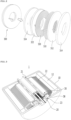
- FIG. 1 is a sectionally perspective view of a conventional non-contact wound rotor synchronous motor to which technology for connecting a rotor of a motor to an external power source is applied in a non-contact manner
- FIG. 2 is an exploded perspective view of a transformer that is essential for electrically connecting the rotor of the motor to the external power source in the non-contact manner in FIG. 1 .
- the conventional wound rotor synchronous motor includes a motor housing 100, and a motor shaft 200, which is rotatably supported within the motor housing 100 by bearings.
- a stator 120 is coupled inside the motor housing 100, and a rotor 220, which generates electromagnetic force by interacting electromagnetically with the stator 120 to rotate the motor shaft 200, is installed on the motor shaft 200.
- the rotor 220 is electrically connected to an external power source through a transformer 300 which includes two opposing coils, without direct contact.
- a rectifier 400 is installed between the transformer 300 and the rotor 220 so that the current from the external power source is transformed to an appropriate level through the transformer 300, is converted from AC to DC by the rectifier, and then, is supplied to the rotor 220.
- the transformer 300 includes a primary coil 310 on the stator side installed in the motor housing 100 and a secondary coil 320 on the rotor side, which is coupled to the motor shaft 200 and rotates in synchronization with the rotor 220.
- the primary coil 310 and the secondary coil 320 are arranged to face each other with a predetermined distance (air gap), and a primary ferrite core 312 and a secondary ferrite core 322, which are respectively fixed to the motor housing 100 and the motor shaft 200, respectively accommodate the primary coil 310 and the secondary coil 320.
- a reference numeral 314 indicates a primary ferrite case covering the primary ferrite core 312, and a reference numeral 324 indicates a secondary ferrite case covering the secondary ferrite core 322.
- the transformer which has the structure that the primary and secondary coils face each other has a problem in that since the secondary coil and the secondary ferrite core, which rotate with the motor shaft during the operation of the motor are simply spaced apart from the primary coil and the primary ferrite core, which do not rotate, with the predetermined air gap of less than 1 mm, the rotating secondary coil collides with the stationary primary coil during the rotation, leading to damage or scratches on the cores.
- ferrite materials used in the primary and secondary ferrite cores for concentration of magnetic flux and magnetic shielding are prone to breaking. Accordingly, in electric vehicles, which are exposed to harsher vibration environments compared to other industrial motors, the ferrite cores are highly concerned about damages due to road shocks during vehicle driving, thus lowering durability and reliability of the motor.
- the secondary coil and the secondary ferrite core are located on the exterior of the motor shaft and rotate together with the rotor, they are subject to strong mechanical stresses due to centrifugal forces, so have a further higher risk of damage.
- Patent Document 1 Korean Patent Publication No. 10-2018-0015450 (Published on February 13, 2018 )
- the present invention has been made in view of the above-mentioned problems occurring in the related art, and it is an objective of the present invention to provide a non-contact rotary transformer, which can realize an electrical connection between an external power source and a rotor with a wider air gap than that of the conventional technology having the structure that coils face each other, and a motor comprising the same.
- a non-contact rotary transformer which is a device for connecting a rotor of a motor to an external power source in a non-contact manner, including: a core part arranged inside a hollow motor shaft in a coaxial structure with a motor shaft; a primary coil part installed on the outer circumferential surface of the core part; a secondary coil part installed on an inner circumferential surface of the motor shaft and surrounding the primary coil part at a predetermined interval (air gap) therefrom; and a rectifier circuit part coupled to the motor shaft, rotating in synchronization with the motor shaft, and electrically connected to the secondary coil part.
- the core part is installed inside the motor shaft through one or more internal bearings, such that the core part and the primary coil part are free from the rotation of the motor shaft, and the secondary coil part installed on the inner circumferential surface of the motor shaft performs a rotational motion in synchronization with the motor shaft.
- the internal bearings include: a front bearing installed between the motor shaft and the core part in front of the primary and secondary coil parts; and a rear bearing installed between the motor shaft and the core part behind the primary and secondary coil parts.
- a hole or a groove for inducing a cable of the primary coil part from the outside to the inside of the motor shaft is formed on the central part or the outer surface of the core.
- a shielding member for magnetic shielding is installed between the secondary coil part and the motor shaft.
- the core part is made of magnetic material and is formed in a round bar shape, and the core part is made of stainless steel.
- the rectifier circuit part applied to the non-contact rotary transformer according to an aspect of the present invention is installed outside the motor shaft.
- the rectifier circuit part is accommodated in a metal receptor coupled to the outer circumferential surface of one end of the motor shaft, and the metal receptor is made of aluminum.
- the rectifier circuit part is installed inside the motor shaft.
- the rectifier circuit part may be embedded inside (hollow part) of the motor shaft together with the core part and the coil parts.
- two or more primary coil parts are provided, and secondary coil parts are configured to correspond to each of the two or more primary coil parts.
- a motor including: a motor housing; a hollow motor shaft rotatably supported at the center of the motor housing; a stator coupled inside the motor housing; a rotor coupled to the motor shaft, and generating rotational force for rotating the motor shaft by interaction with the stator t; and a non-contact rotary transformer installed in the hollow motor shaft according to one of the previously described aspects.
- the non-contact rotary transformer and the motor comprising the same can realize the electrical connection between the external power source and the rotor with a wider air gap (distance between two coils) than that of the conventional technology having the coils facing each other, and can significantly improve durability of the motor since the structural design significantly reduces the possibility of physical contact and damages between the coils.
- the non-contact rotary transformer and the motor comprising the same use stainless steel instead of ferrite, which is less durable, for the cores, thereby enhancing durability and reliability of the motor.
- non-contact rotary transformer and the motor comprising the same can reduce costs and realize the motor at a more economical cost since stainless steel is relatively cheaper than ferrite, thereby increasing price competitiveness.
- the size of the motor can be significantly reduced compared to that of the conventional wound rotor synchronous motor which has the rotary transformer mounted on the exterior of the motor shaft, thereby responding to the market demands for miniaturization, facilitating control by reducing the rotational inertia of the rotor, and eliminating the complexity of needing additional balancing members to address mass imbalance in the rotation direction of the rotor.
- terms, such as “first” or “second” may be used in the specification to describe various components but are not restricted to the above terms. The terms may be used to discriminate one component from another component.
- unit and module indicate a unit for processing at least one function or operation, wherein the unit and the block may be embodied as hardware or software or embodied by combining hardware and software.
- FIG. 3 is a sectionally perspective view of a wound rotor synchronous motor to which non-contact rotary transformer according to an embodiment of the present invention is applied. Referring to FIG. 3 , the overall configuration of the wound rotor synchronous motor to which a non-contact rotary transformer according to an embodiment of the present invention is applied will be described in brief.
- the non-contact wound rotor synchronous motor 1 includes a motor housing 10 and a motor shaft 20 installed along the center of the motor housing 10.
- the motor shaft 20 is configured in the center of the motor housing 10 through bearings, more specifically, a front bearing 21 and a rear bearing 23 to be freely rotatable, and a rotor 22 is coupled to the outer circumferential surface of the motor shaft.
- the rotor 22 may be a field system made of electromagnets operated by direct current. Moreover, inside the motor housing 10, a stator 12 is installed corresponding to the rotor 22.
- the stator 12 may be an armature made of electromagnets operated by alternating current supplied from an inverter of an electric vehicle or an external power source.
- the rotor 22 can be electrically connected to an external power source through a rotary transformer 30 without direct contact according to an embodiment of the present invention.
- the rotary transformer 30 includes a rectifier circuit part 38, and thus, the power supplied from outside can be transformed to an appropriate level and converted from AC to DC through the rotary transformer 30 according to an embodiment of the present invention, and then, supplied to the field power of the rotor 22.
- the rotary transformer 30 may be entirely or partially embedded within the motor shaft 20.
- all components except the rectifier circuit part 38 may be embedded within the hollow motor shaft 20, or as will be described in another embodiment illustrated in FIG. 18 , all components including the rectifier circuit part 38 may be installed within the hollow motor shaft 20.
- FIG. 4 is an enlarged view of the rotary transformer in FIG. 3 , showing the configuration of the rotary transformer in which all components except the rectifier circuit part 38 are embedded within the motor shaft.
- FIG. 5 is an exploded view illustrating essential components of the rotary transformer illustrated in FIG. 4 .
- the rotary transformer 30 includes a core part 32.
- the core part 32 may be arranged concentrically inside the hollow motor shaft 20, that is, may be installed in a concentric structure within the motor shaft 20 through one or more internal bearings, preferably, two bearings (a front bearing B1 and a rear bearing B2) spaced apart from each other at a distance within the motor shaft 20 illustrated in FIG. 2 .
- the core part 32 is made of a magnetic material and can have a round rod form of which a cross-section is in a circular shape.
- the core part 32 can be a round rod made of the same material as the motor housing 10 and the motor shaft 20, such as stainless steel.
- the core part 32 made from stainless steel can show motor characteristics similar to the core made of ferrite, which is less durable, and enhance durability, thereby improving motor reliability and reducing costs.
- a primary coil part 34 is configured on On the outer circumferential surface of the core part 32.
- the primary coil part 34 can be formed by continuously winding a conductive cable along the outer surface of the core part 32, and a power input terminal 345 of the conductive cable of the primary coil part 34 can be connected to an inverter of an electric vehicle or an external power source.
- the conductive cable may be, for example, a Litz wire, a flat ribbon wire, or an insulated wire.
- the power input terminal 345 of the conductive cable of the primary coil part 34 may be introduced from the outside to the inside of the motor shaft 20 through an opening at one end of the motor shaft 20 along a groove 33 formed longitudinally on the outer surface of the core part 32, or may pass through a hole formed longitudinally in the center of the core part 32 or a hole formed in the inner race of the front bearing B1 and extend from the outside of the motor shaft 20 to the position where the primary coil part 34 is formed (not illustrated).
- a secondary coil part 36 is installed on the inner circumferential surface of the motor shaft 20.
- the secondary coil part 36 may be the same conductive cable as the cable of the primary coil part 34. More specifically, the secondary coil part 36 can be formed by continuously winding the conductive cable in a coil form, and can be installed on the inner circumferential surface of the motor shaft 20 to surround the primary coil part 34 to be spaced apart from the primary coil part 34 at a predetermined distance (air gap).
- the core part 32 can be installed in a concentric structure within the motor shaft 20 through one or more internal bearings B1 and B2. Therefore, the core part 32 and the primary coil part 34 installed thereon are free from the rotation of the motor shaft 20, and the secondary coil part 36 surrounding the primary coil part 34 inside the motor shaft 20 is installed on the inner circumferential surface of the motor shaft 20 to perform rotational motion synchronized with the motor shaft 20.
- the internal bearings that support the core part 32 within the motor shaft 20 to be rotatable can preferably include a front bearing B1 and a rear bearing B2, as illustrated in FIG. 4 .
- the front bearing B1 can be installed between the motor shaft 20 and the core part 32 in front of the primary coil part 34 and the secondary coil part 36
- the rear bearing B2 can be installed between the motor shaft 20 and the core part 32 behind the primary coil part 34 and the secondary coil part 36.
- a shielding member 37 made of a magnetic material, may be installed between the secondary coil part 36 and the motor shaft 20.
- the shielding member 37 is intended to isolate the primary coil part 34 and the secondary coil part 36 from the external magnetic field, and can be formed in a cylindrical shape longer than the secondary coil part 36 to accommodate the entirety of the secondary coil part 36 surrounding the primary coil part 34.
- the shielding member 37 can be an aluminum cylinder longer than the secondary coil part 36.
- the conductive cable forming the secondary coil part 36 can be electrically connected to the rectifier circuit part 38.
- the rectifier circuit part 38 can be installed outside the motor shaft 20.
- the rectifier circuit part 38 can be coupled to the motor shaft 20 in a space formed between the shear surface of the rotor 22 and the front end plate (not labeled) of the motor housing 10 to perform rotational motion synchronized with the motor shaft 20.
- the rectifier circuit part 38 may include a substrate and rectifying elements mounted thereon, such as diodes, and can be accommodated in a metal receptor 28 coupled to the outer surface of one end of the motor shaft 20.
- the substrate may be connected to the conductive cable (cable of the secondary coil part 36) withdrawn outward from the inside of the motor shaft 20 through a cable withdrawing hole 205 formed in the motor shaft 20, and the metal receptor 28 can be made of aluminum.
- the applied alternating current causes a current to flow in the primary coil part 34, and the current flowing in the primary coil part 34 induces a secondary current (transformed current, or alternating current) in the secondary coil part 36, spaced at a predetermined distance by the principle of electromagnetic induction.
- the secondary current generated in the secondary coil part 36 is provided to the rectifier circuit part 38 through the power output terminal 365 of the conductive cable of the secondary coil part 36. After being converted from AC to DC in the rectifier circuit part 38, the current is supplied to the rotor 22 electrically connected to the output side of the rectifier circuit part 38. As a result, the rotor 22 becomes magnetized, and synchronously rotates due to the induced magnetic field of the stator 12.
- the power output terminal 365 of the conductive cable of the secondary coil part 36 can be withdrawn from the inside to the outside of the motor shaft 20 through the cable withdrawing hole 205 radially formed in the motor shaft 20, and then, can be electrically connected to the rectifier circuit part 38 accommodated in the metal receptor 28 coupled to the outside of the motor shaft 20.
- FIGS. 6 and 7 are graphic views showing simulation results of a conventional non-contact rotary transformer having a structure that two coils face each other.
- the coil was made of copper, and permeability of the ferrite core was set to 3300.
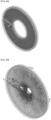
- FIG. 6A shows the density of alternating currents in the primary and secondary coils when the distance between the primary coil and the secondary coil, namely, the air gap, in the conventional non-contact rotary transformer having the structure that two coils face each other was 1 mm.
- the frequency of the alternating current used in an inverter of an electric vehicle is 20 kHz
- the alternating current was 20 kHz, and the results are shown in the table of FIG. 8 .
- FIG. 6B shows the magnetic flux between the primary ferrite core excited in the primary coil and the secondary ferrite core excited in the secondary coil when the distance between the primary coil and the secondary coil, namely, the air gap, in the conventional non-contact rotary transformer was 1 mm.
- the frequency of the alternating current used in an inverter of an electric vehicle is 20 kHz
- the alternating current was 20 kHz, and the results are shown in the table of FIG. 8 .
- FIGS. 7A to 7D illustrate the distribution of magnetic flux for each case when the air gap (the distance between the opposing primary and secondary coils) in the conventional non-contact rotary transformer was 1 mm, 2 mm, 3 mm, and 4 mm, respectively.
- FIG. 8 is a table showing simulation values of the graphic results illustrated in FIGS. 6 and 7 . That is, the drawings show the simulation results of each of the cases when the air gap moves from 1 mm to 4 mm.
- the coupling coefficients of the rotary transformer decrease as the air gap increases.
- the coupling coefficients are characteristics indicating the efficiency of the transformer, and is closely related to transformer efficiency. More specifically, the coupling coefficients are proportional to transformer efficiency. Therefore, as the coupling coefficients increase, the transformer efficiency also increases. The principle is well-known and thus a detailed description will be omitted.
- the magnetic flux between the primary ferrite core excited in the primary coil and the secondary ferrite core excited in the secondary coil forms a robust and small closed loop. It is because the primary coil which is the primary side of the rotary transformer and secondary coil which is the secondary side facilitate efficient energy exchange through the ferrite core.
- the conventional non-contact rotary transformer having the structure that two coils face each other decreases the transformer efficiency as the distance between the primary coil and the secondary coil, namely the air gap, increases.
- the conventional non-contact rotary transformer having the structure that two coils face each other mainly uses ferrite cores as the magnetic material for the primary and secondary coils for concentration of magnetic flux and magnetic shielding. Ferrite has already been verified for its properties and is commonly used because there are no alternatives. However, despite there is a risk of damage due to the air gap during highspeed rotation, it continues to be used.
- FIGS. 9 and 10 show the simulation results when replacing the ferrite core with a stainless steel core, which was the same material used for the motor housing and the hollow motor shaft, in the conventional non-contact rotary transformer having the structure that the two coils face each other.
- the coil was made of copper
- the ferrite core was made of stainless steel.
- FIG. 9A shows the density of alternating currents in the primary and secondary coils when the distance between the primary coil and the secondary coil, namely, the air gap, in the case where the ferrite core was replaced with a stainless steel core in the conventional non-contact rotary transformer having the structure that two coils face each other is 1 mm.
- the frequency of the alternating current used in an inverter of an electric vehicle is 20 kHz
- the alternating current was 20 kHz, and the results are shown in the table of FIG. 8 .
- FIG. 9B shows the magnetic flux between the primary stainless steel core excited in the primary coil and the secondary stainless steel core excited in the secondary coil in the same structure as FIG. 9A .
- the frequency of the alternating current used in an inverter of an electric vehicle is 20 kHz
- the alternating current was 20 kHz, and the results are shown in the table of FIG. 11 .
- FIGS. 10A to 10D illustrate the distribution of magnetic flux for each case when only the air gap (the distance between the opposing primary and secondary coils) in the same configuration as FIG. 9 was changed to 1 mm, 2 mm, 3 mm, and 4 mm.
- FIG. 11 is a table showing simulation values of the graphic results illustrated in FIGS. 9 and 10 . That is, the drawings show the simulation results of each of the cases when the air gap moves from 1 mm to 4 mm.
- FIGS. 12 and 13 are graphic views showing simulation results of a rotary transformer having a structure that two coils are concentrically arranged inside a motor shaft according to an embodiment of the present invention.
- a ferrite core with a permeability of 3300 was used for the primary core part, and the coil was made of copper.
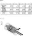
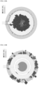
- FIG. 12A shows the simulation results indicating the density of alternating currents in the primary coil part and the secondary coil part when the distance between the primary coil part and the secondary coil part of the rotary transformer according to an embodiment of the present invention was 1 mm.
- the frequency of the alternating current used in an inverter of an electric vehicle is 20 kHz, it was analyzed that the alternating current was 20 kHz, and the results are shown in the table of FIG. 8 .
- FIG. 12B shows the magnetic flux between the primary core part (ferrite core) excited in the primary coil part and the secondary core part (ferrite material as a shielding member) excited in the secondary coil part when the distance between the primary coil part and the secondary coil part, namely, the air gap, was 1 mm, as illustrated in FIG. 12A .
- the frequency of the alternating current used in an inverter of an electric vehicle is 20 kHz
- the alternating current was 20 kHz, and the results are shown in the table of FIG. 14 .
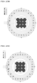
- FIG. 13A to 13D illustrate the distribution of magnetic flux for each case when the air gap (the distance between the opposing primary and secondary coils) of the primary coil part and the secondary coil part in the same configuration as FIG. 12A was 1 mm, 2 mm, 3 mm, and 4 mm, respectively.
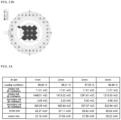
- FIG. 14 is a table showing simulation values of the graphic results illustrated in FIGS. 12 and 13 .
- the coupling coefficients of the rotary transformer decrease as the air gap increases, unlike the previous simulation results (see FIG. 8 , the simulation results of the conventional rotary transformer having the structure that two coils face each other with the air gap), the change (decrease volume) in the coupling coefficients is relatively small. In other words, it means that the rotary transformer can be configured for all air gaps in the same configuration as the present invention.
- FIGS. 15 and 16 also depict simulation results for a rotary transformer with a configuration similar to an embodiment of the present invention, where two coils are concentrically arranged inside the motor shaft. Unlike previous simulations, these FIGS. show the results when the primary core part is replaced with stainless steel.
- FIG. 15A shows the simulation results indicating the density of alternating currents in the primary coil part and the secondary coil part when the distance between the primary coil part and the secondary coil part of the rotary transformer according to an embodiment of the present invention was 1 mm.
- the frequency of the alternating current used in an inverter of an electric vehicle is 20 kHz
- the alternating current was 20 kHz, and the results are shown in the table of FIG. 8 .
- FIG. 15B shows the magnetic flux between the primary core part (stainless steel) excited in the primary coil part and the secondary core part (hollow motor shaft made of stainless steel) excited in the secondary coil part when the distance between the primary coil part and the secondary coil part, namely, the air gap, was 1 mm, as illustrated in FIG. 15A .
- FIG. 16A to 16D illustrate the distribution of magnetic flux for each case when the air gap (the distance between the opposing primary and secondary coils) of the primary coil part and the secondary coil part in the same configuration as FIG. 12A was 1 mm, 2 mm, 3 mm, and 4 mm, respectively.
- FIG. 17 is a table showing simulation values of the graphic results illustrated in FIGS. 15 and 16 .
- the coupling coefficients of the rotary transformer decrease as the air gap increases, and compared with the previous simulation results (the simulation results of the case that the primary core part is formed of the ferrite core and the secondary core part is formed of ferrite), the change (decrease volume) in the coupling coefficients is not significant.
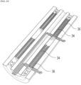
- FIGS. 18 and 19 are sectionally perspective views of a non-contact rotary transformer according to another preferred embodiment of the present invention. Unlike the previous embodiment where only the rectifier circuit part is located outside the motor shaft, in FIG. 18 , the core part 32, the primary coil part 34, the secondary coil part 36, and the rectifier circuit part 38 are also embedded inside the hollow motor shaft 20, and in FIG. 19 , a plurality of coil groups are configured inside the hollow motor shaft 20.
- the core part 32 is formed as a hollow tube, such that the power input terminal 345 of the conductive cable of the primary coil part 34 passes through the inside of the core part 32 and is induced to the position where the primary coil part 34 is formed and the power output terminal of the secondary coil part 36 passes through the outer race of the rear bearing B2 and is electrically connected to the rectifier circuit part 38 at the rear.
- the wound rotor synchronous motor can be manufactured in a more robust and compact design.
- the rectifier circuit part illustrated in FIG. 18 is less affected by rotational inertia, thereby lowering the possibility of component damage, and simplifying control of the rectifier circuit.
- the configuration can double the power supplied to the rotor per unit time compared to the configuration with a single coil group, so can be usefully utilized in high-performance wound rotor synchronous motors that require high output.
- the non-contact rotary transformer and the motor comprising the same can realize the electrical connection between the external power source and the rotor with a wider air gap (distance between two coils) than that of the conventional technology having the coils facing each other, and can significantly improve durability of the motor since the structural design significantly reduces the possibility of physical contact and damages between the coils.
- the non-contact rotary transformer and the motor comprising the same use stainless steel instead of ferrite, which is less durable, for the cores, thereby enhancing durability and reliability of the motor.
- non-contact rotary transformer and the motor comprising the same can reduce costs and realize the motor at a more economical cost since stainless steel is relatively cheaper than ferrite, thereby increasing price competitiveness.
- the size of the motor can be significantly reduced compared to that of the conventional wound rotor synchronous motor which has the rotary transformer mounted on the exterior of the motor shaft, thereby responding to the market demands for miniaturization, facilitating control by reducing the rotational inertia of the rotor, and eliminating the complexity of needing additional balancing members to address mass imbalance in the rotation direction of the rotor.
Landscapes
- Engineering & Computer Science (AREA)
- Power Engineering (AREA)
- Computer Networks & Wireless Communication (AREA)
- Physics & Mathematics (AREA)
- Electromagnetism (AREA)
- Motor Or Generator Frames (AREA)
- Synchronous Machinery (AREA)
Abstract
Description
- The present invention relates to an electric supply device for supplying electricity to a rotor of a motor, and more specifically, to a non-contact rotary transformer, which connects the rotor of the motor to an external power source in a non-contact manner, and a motor comprising the same.
- A wound rotor synchronous motor is primarily used in an electric vehicle since having superior torque and power density when compared to other motors. In general, the wound rotor synchronous motor employs a method of electrically connecting the rotor inside the motor to an external power source using a slip ring and a brush, which are in mechanical contact with each other, to supply electricity.
- However, the conventional contact type electric supply method using the slip ring and the brush has a problem that the brush is deformed or damaged due to continuous friction between the slip ring rotating along with the motor shaft and the brush fixed to the motor housing during driving of the motor. Accordingly, there is a risk of a fire due to sparks occurring between the slip ring and the brush. Additionally, wear on the brushes may produce a significant amount of dust.
- To overcome the above problems of the conventional art, a technology to electrically connect a rotor to an external power source in a non-contact manner has been proposed. The technology utilizes the phenomenon where, when current flows through one of two facing coils, voltage is induced into the other coil such that current flows (electromagnetic induction), so an electrical connection between the external power source and the rotor can be realized without any direct contact between the components.
-
FIG. 1 is a sectionally perspective view of a conventional non-contact wound rotor synchronous motor to which technology for connecting a rotor of a motor to an external power source is applied in a non-contact manner, andFIG. 2 is an exploded perspective view of a transformer that is essential for electrically connecting the rotor of the motor to the external power source in the non-contact manner inFIG. 1 . - Referring to
FIGS. 1 and2 , the conventional wound rotor synchronous motor includes amotor housing 100, and amotor shaft 200, which is rotatably supported within themotor housing 100 by bearings. Astator 120 is coupled inside themotor housing 100, and arotor 220, which generates electromagnetic force by interacting electromagnetically with thestator 120 to rotate themotor shaft 200, is installed on themotor shaft 200. - The
rotor 220 is electrically connected to an external power source through atransformer 300 which includes two opposing coils, without direct contact. Arectifier 400 is installed between thetransformer 300 and therotor 220 so that the current from the external power source is transformed to an appropriate level through thetransformer 300, is converted from AC to DC by the rectifier, and then, is supplied to therotor 220. - The
transformer 300 includes aprimary coil 310 on the stator side installed in themotor housing 100 and asecondary coil 320 on the rotor side, which is coupled to themotor shaft 200 and rotates in synchronization with therotor 220. - The
primary coil 310 and thesecondary coil 320 are arranged to face each other with a predetermined distance (air gap), and aprimary ferrite core 312 and asecondary ferrite core 322, which are respectively fixed to themotor housing 100 and themotor shaft 200, respectively accommodate theprimary coil 310 and thesecondary coil 320. - In
FIG. 2 , areference numeral 314 indicates a primary ferrite case covering theprimary ferrite core 312, and areference numeral 324 indicates a secondary ferrite case covering thesecondary ferrite core 322. - However, the transformer which has the structure that the primary and secondary coils face each other has a problem in that since the secondary coil and the secondary ferrite core, which rotate with the motor shaft during the operation of the motor are simply spaced apart from the primary coil and the primary ferrite core, which do not rotate, with the predetermined air gap of less than 1 mm, the rotating secondary coil collides with the stationary primary coil during the rotation, leading to damage or scratches on the cores.
- Particularly, ferrite materials used in the primary and secondary ferrite cores for concentration of magnetic flux and magnetic shielding are prone to breaking. Accordingly, in electric vehicles, which are exposed to harsher vibration environments compared to other industrial motors, the ferrite cores are highly concerned about damages due to road shocks during vehicle driving, thus lowering durability and reliability of the motor.
- Additionally, because the secondary coil and the secondary ferrite core are located on the exterior of the motor shaft and rotate together with the rotor, they are subject to strong mechanical stresses due to centrifugal forces, so have a further higher risk of damage.
- In addition, in the structure where two coils face each other, since the amount of power supplied to the rotor is proportional to the area where the coils face each other, higher power motors require radially expanded coils. In this case, the size of the motor must be increased as much as the volume of the coil is increased. However, the above counters the recent trend towards motor miniaturization, presenting a problem in meeting the demands for smaller motor designs.
- Patent Document 1:
Korean Patent Publication No. 10-2018-0015450 (Published on February 13, 2018 - Accordingly, the present invention has been made in view of the above-mentioned problems occurring in the related art, and it is an objective of the present invention to provide a non-contact rotary transformer, which can realize an electrical connection between an external power source and a rotor with a wider air gap than that of the conventional technology having the structure that coils face each other, and a motor comprising the same.
- It is another objective of the present invention to provide a non-contact rotary transformer, which instead of fragile ferrite, uses materials with higher durability such as stainless steel for cores of the transformer, thereby enhancing durability, and a motor comprising the same.
- It is a further objective of the present invention to provide a non-contact rotary transformer, which is advantageous for miniaturization of the motor compared to the conventional rotary transformer mounted outside the motor shaft, and a motor comprising the same.
- To accomplish the above-mentioned objects, according to the present invention, there is provided a non-contact rotary transformer, which is a device for connecting a rotor of a motor to an external power source in a non-contact manner, including: a core part arranged inside a hollow motor shaft in a coaxial structure with a motor shaft; a primary coil part installed on the outer circumferential surface of the core part; a secondary coil part installed on an inner circumferential surface of the motor shaft and surrounding the primary coil part at a predetermined interval (air gap) therefrom; and a rectifier circuit part coupled to the motor shaft, rotating in synchronization with the motor shaft, and electrically connected to the secondary coil part.
- In the non-contact rotary transformer, the core part is installed inside the motor shaft through one or more internal bearings, such that the core part and the primary coil part are free from the rotation of the motor shaft, and the secondary coil part installed on the inner circumferential surface of the motor shaft performs a rotational motion in synchronization with the motor shaft.
- Here, the internal bearings include: a front bearing installed between the motor shaft and the core part in front of the primary and secondary coil parts; and a rear bearing installed between the motor shaft and the core part behind the primary and secondary coil parts.
- Moreover, a hole or a groove for inducing a cable of the primary coil part from the outside to the inside of the motor shaft is formed on the central part or the outer surface of the core.
- Furthermore, a shielding member for magnetic shielding is installed between the secondary coil part and the motor shaft.
- Additionally, the core part is made of magnetic material and is formed in a round bar shape, and the core part is made of stainless steel.
- As a preferred embodiment, the rectifier circuit part applied to the non-contact rotary transformer according to an aspect of the present invention is installed outside the motor shaft.
- In this case, the rectifier circuit part is accommodated in a metal receptor coupled to the outer circumferential surface of one end of the motor shaft, and the metal receptor is made of aluminum.
- As another preferred embodiment, the rectifier circuit part is installed inside the motor shaft.
- As another preferred embodiment, the rectifier circuit part may be embedded inside (hollow part) of the motor shaft together with the core part and the coil parts.
- As occasion demands, two or more primary coil parts are provided, and secondary coil parts are configured to correspond to each of the two or more primary coil parts.
- According to another aspect of the present invention, there is provided a motor including: a motor housing; a hollow motor shaft rotatably supported at the center of the motor housing; a stator coupled inside the motor housing; a rotor coupled to the motor shaft, and generating rotational force for rotating the motor shaft by interaction with the stator t; and a non-contact rotary transformer installed in the hollow motor shaft according to one of the previously described aspects.
- According to embodiments of the present invention, the non-contact rotary transformer and the motor comprising the same can realize the electrical connection between the external power source and the rotor with a wider air gap (distance between two coils) than that of the conventional technology having the coils facing each other, and can significantly improve durability of the motor since the structural design significantly reduces the possibility of physical contact and damages between the coils.
- Moreover, when the same metal material as the motor housing and and the motor shaft, such as stainless steel, instead of structurally fragile ferrite is used for the core, it does not significantly affect the change (decrease volume) in the coupling coefficient, which is characteristics indicating transformer efficiency. In other words, the non-contact rotary transformer and the motor comprising the same use stainless steel instead of ferrite, which is less durable, for the cores, thereby enhancing durability and reliability of the motor.
- Furthermore, the non-contact rotary transformer and the motor comprising the same can reduce costs and realize the motor at a more economical cost since stainless steel is relatively cheaper than ferrite, thereby increasing price competitiveness.
- In addition, as most or all components of the rotary transformer are installed inside the hollow motor shaft, the size of the motor can be significantly reduced compared to that of the conventional wound rotor synchronous motor which has the rotary transformer mounted on the exterior of the motor shaft, thereby responding to the market demands for miniaturization, facilitating control by reducing the rotational inertia of the rotor, and eliminating the complexity of needing additional balancing members to address mass imbalance in the rotation direction of the rotor.
-
-
FIG. 1 is a sectionally perspective view of a conventional non-contact wound rotor synchronous motor to which technology for connecting a rotor of a motor to an external power source is applied in a non-contact manner. -
FIG. 2 is an exploded perspective view of a transformer that is essential for electrically connecting the rotor of the motor to the external power source in the non-contact manner inFIG. 1 . -
FIG. 3 is a sectionally perspective view of a wound rotor synchronous motor to which a non-contact rotary transformer according to an embodiment of the present invention is applied. -
FIG. 4 is an enlarged view of the rotary transformer inFIG. 3 . -
FIG. 5 is an exploded view illustrating essential components of the rotary transformer illustrated inFIG. 4 . -
FIGS. 6 and7 are graphic views showing simulation results of a conventional non-contact rotary transformer having a structure that two coils face each other. -
FIG. 8 is a table showing the simulation results ofFIGS. 6 and7 . -
FIGS. 9 and10 are graphic views showing simulation results when cores are made of stainless steel, instead of ferrite core, in the conventional non-contact rotary transformer having a structure that two coils face each other. -
FIG. 11 is a table showing the simulation results ofFIGS. 9 and10 . -
FIGS. 12 and13 are graphic views showing simulation results of a rotary transformer having a structure that two coils are concentrically arranged inside a motor shaft according to an embodiment of the present invention. -
FIG. 14 is a table showing the simulation results ofFIGS. 12 and13 . -
FIGS. 15 and16 are graphic views showing simulation results when a core part is made of stainless steel, instead of ferrite core, in the rotary transformer having the structure that two coils are concentrically arranged inside a motor shaft. -
FIG. 17 is a table showing the simulation results ofFIGS. 15 and16 . -
FIG. 18 is a sectionally perspective view illustrating a non-contact rotary transformer according to another embodiment of the present invention. -
FIG. 19 is a sectionally perspective view illustrating a non-contact rotary transformer according to a further embodiment of the present invention. - Hereinafter, preferred embodiments of the present invention will be described in detail with reference to the accompanying drawings.
- In description of the present invention, terms used in the following description are intended to merely describe specific embodiments, but not intended to limit the invention. An expression of the singular number includes an expression of the plural number, so long as it is clearly read differently.
- The terms such as "include" and "have" are intended to indicate that features, numbers, steps, operations, elements, components, or combinations thereof used in the following description exist and it should thus be understood that the possibility of existence or addition of one or more other different features, numbers, steps, operations, elements, components, or combinations thereof is not excluded.
- Furthermore, terms, such as "first" or "second" may be used in the specification to describe various components but are not restricted to the above terms. The terms may be used to discriminate one component from another component.
- In the following description, terms such as "unit" and "module" indicate a unit for processing at least one function or operation, wherein the unit and the block may be embodied as hardware or software or embodied by combining hardware and software.
- In description of the present invention with reference to the accompanying drawings, like elements are referenced by like reference numerals or signs regardless of the drawing numbers and description thereof is not repeated. In the description, details of well-known features and techniques may be omitted to avoid unnecessarily obscuring the presented embodiments.
-
FIG. 3 is a sectionally perspective view of a wound rotor synchronous motor to which non-contact rotary transformer according to an embodiment of the present invention is applied. Referring toFIG. 3 , the overall configuration of the wound rotor synchronous motor to which a non-contact rotary transformer according to an embodiment of the present invention is applied will be described in brief. - Referring to
FIG. 3 , the non-contact wound rotor synchronous motor 1 according to the present invention includes amotor housing 10 and amotor shaft 20 installed along the center of themotor housing 10. Themotor shaft 20 is configured in the center of themotor housing 10 through bearings, more specifically, afront bearing 21 and arear bearing 23 to be freely rotatable, and arotor 22 is coupled to the outer circumferential surface of the motor shaft. - The
rotor 22 may be a field system made of electromagnets operated by direct current. Moreover, inside themotor housing 10, astator 12 is installed corresponding to therotor 22. Thestator 12 may be an armature made of electromagnets operated by alternating current supplied from an inverter of an electric vehicle or an external power source. - Under the control of a controller, when alternating current and direct current are respectively applied to the
stator 12 and therotor 22, due to an electromagnetic interaction between thestator 12 and therotor 22, a force (electromagnetic force) that causes therotor 22 to rotate themotor shaft 20 is generated. The force allows themotor shaft 20 to rotate, thereby outputting rotational power. The principle of force generation due to the interaction between thestator 12 and therotor 22 is a known concept, and hence detailed description will be omitted. - The
rotor 22 can be electrically connected to an external power source through arotary transformer 30 without direct contact according to an embodiment of the present invention. Therotary transformer 30 includes arectifier circuit part 38, and thus, the power supplied from outside can be transformed to an appropriate level and converted from AC to DC through therotary transformer 30 according to an embodiment of the present invention, and then, supplied to the field power of therotor 22. - The
rotary transformer 30 according to an embodiment of the present invention may be entirely or partially embedded within themotor shaft 20. For instance, as illustrated inFIG. 3 , all components except therectifier circuit part 38 may be embedded within thehollow motor shaft 20, or as will be described in another embodiment illustrated inFIG. 18 , all components including therectifier circuit part 38 may be installed within thehollow motor shaft 20. -
FIG. 4 is an enlarged view of the rotary transformer inFIG. 3 , showing the configuration of the rotary transformer in which all components except therectifier circuit part 38 are embedded within the motor shaft.FIG. 5 is an exploded view illustrating essential components of the rotary transformer illustrated inFIG. 4 . - Referring to
FIGS. 4 and 5 , therotary transformer 30 according to an embodiment of the present invention includes acore part 32. Thecore part 32 may be arranged concentrically inside thehollow motor shaft 20, that is, may be installed in a concentric structure within themotor shaft 20 through one or more internal bearings, preferably, two bearings (a front bearing B1 and a rear bearing B2) spaced apart from each other at a distance within themotor shaft 20 illustrated inFIG. 2 . - The
core part 32 is made of a magnetic material and can have a round rod form of which a cross-section is in a circular shape. Thecore part 32 can be a round rod made of the same material as themotor housing 10 and themotor shaft 20, such as stainless steel. Thecore part 32 made from stainless steel can show motor characteristics similar to the core made of ferrite, which is less durable, and enhance durability, thereby improving motor reliability and reducing costs. - A
primary coil part 34 is configured on On the outer circumferential surface of thecore part 32. Theprimary coil part 34 can be formed by continuously winding a conductive cable along the outer surface of thecore part 32, and apower input terminal 345 of the conductive cable of theprimary coil part 34 can be connected to an inverter of an electric vehicle or an external power source. Here, the conductive cable may be, for example, a Litz wire, a flat ribbon wire, or an insulated wire. - The
power input terminal 345 of the conductive cable of theprimary coil part 34 may be introduced from the outside to the inside of themotor shaft 20 through an opening at one end of themotor shaft 20 along agroove 33 formed longitudinally on the outer surface of thecore part 32, or may pass through a hole formed longitudinally in the center of thecore part 32 or a hole formed in the inner race of the front bearing B1 and extend from the outside of themotor shaft 20 to the position where theprimary coil part 34 is formed (not illustrated). - A
secondary coil part 36 is installed on the inner circumferential surface of themotor shaft 20. Thesecondary coil part 36 may be the same conductive cable as the cable of theprimary coil part 34. More specifically, thesecondary coil part 36 can be formed by continuously winding the conductive cable in a coil form, and can be installed on the inner circumferential surface of themotor shaft 20 to surround theprimary coil part 34 to be spaced apart from theprimary coil part 34 at a predetermined distance (air gap). - As described above, the
core part 32 can be installed in a concentric structure within themotor shaft 20 through one or more internal bearings B1 and B2. Therefore, thecore part 32 and theprimary coil part 34 installed thereon are free from the rotation of themotor shaft 20, and thesecondary coil part 36 surrounding theprimary coil part 34 inside themotor shaft 20 is installed on the inner circumferential surface of themotor shaft 20 to perform rotational motion synchronized with themotor shaft 20. - That is, when power is applied, a force (electromagnetic force) to rotate the
motor shaft 20 is generated to therotor 22 by the interaction between therotor 22 and thestator 12. Accordingly, even if themotor shaft 20 rotates, thecore part 32 and theprimary coil part 34 which are concentrically arranged inside themotor shaft 20 do not rotate, and only thesecondary coil part 36 installed on the inner circumferential surface of themotor shaft 20 rotates together with themotor shaft 20. - The internal bearings that support the
core part 32 within themotor shaft 20 to be rotatable can preferably include a front bearing B1 and a rear bearing B2, as illustrated inFIG. 4 . The front bearing B1 can be installed between themotor shaft 20 and thecore part 32 in front of theprimary coil part 34 and thesecondary coil part 36, and the rear bearing B2 can be installed between themotor shaft 20 and thecore part 32 behind theprimary coil part 34 and thesecondary coil part 36. - A shielding
member 37, made of a magnetic material, may be installed between thesecondary coil part 36 and themotor shaft 20. The shieldingmember 37 is intended to isolate theprimary coil part 34 and thesecondary coil part 36 from the external magnetic field, and can be formed in a cylindrical shape longer than thesecondary coil part 36 to accommodate the entirety of thesecondary coil part 36 surrounding theprimary coil part 34. Preferably, the shieldingmember 37 can be an aluminum cylinder longer than thesecondary coil part 36. - The conductive cable forming the
secondary coil part 36 can be electrically connected to therectifier circuit part 38. In an embodiment of the present invention, therectifier circuit part 38 can be installed outside themotor shaft 20. In this case, therectifier circuit part 38 can be coupled to themotor shaft 20 in a space formed between the shear surface of therotor 22 and the front end plate (not labeled) of themotor housing 10 to perform rotational motion synchronized with themotor shaft 20. - The
rectifier circuit part 38 may include a substrate and rectifying elements mounted thereon, such as diodes, and can be accommodated in ametal receptor 28 coupled to the outer surface of one end of themotor shaft 20. The substrate may be connected to the conductive cable (cable of the secondary coil part 36) withdrawn outward from the inside of themotor shaft 20 through acable withdrawing hole 205 formed in themotor shaft 20, and themetal receptor 28 can be made of aluminum. - The process that the external power supply is provided to the field power source of the
rotor 22 through therotary transformer 30 according to an embodiment of the present invention will be described in brief. - The alternating current supplied by an external power source, such as an inverter of an electric vehicle, is applied to the
rotary transformer 30 through thepower input terminal 345 of the conductive cable of theprimary coil part 34. The applied alternating current causes a current to flow in theprimary coil part 34, and the current flowing in theprimary coil part 34 induces a secondary current (transformed current, or alternating current) in thesecondary coil part 36, spaced at a predetermined distance by the principle of electromagnetic induction. - The secondary current generated in the
secondary coil part 36 is provided to therectifier circuit part 38 through thepower output terminal 365 of the conductive cable of thesecondary coil part 36. After being converted from AC to DC in therectifier circuit part 38, the current is supplied to therotor 22 electrically connected to the output side of therectifier circuit part 38. As a result, therotor 22 becomes magnetized, and synchronously rotates due to the induced magnetic field of thestator 12. - Here, the
power output terminal 365 of the conductive cable of thesecondary coil part 36 can be withdrawn from the inside to the outside of themotor shaft 20 through thecable withdrawing hole 205 radially formed in themotor shaft 20, and then, can be electrically connected to therectifier circuit part 38 accommodated in themetal receptor 28 coupled to the outside of themotor shaft 20. -
FIGS. 6 and7 are graphic views showing simulation results of a conventional non-contact rotary transformer having a structure that two coils face each other. Here, as the simulation parameters, the coil was made of copper, and permeability of the ferrite core was set to 3300. -
FIG. 6A shows the density of alternating currents in the primary and secondary coils when the distance between the primary coil and the secondary coil, namely, the air gap, in the conventional non-contact rotary transformer having the structure that two coils face each other was 1 mm. Considering that the frequency of the alternating current used in an inverter of an electric vehicle is 20 kHz, it was analyzed that the alternating current was 20 kHz, and the results are shown in the table ofFIG. 8 . -
FIG. 6B shows the magnetic flux between the primary ferrite core excited in the primary coil and the secondary ferrite core excited in the secondary coil when the distance between the primary coil and the secondary coil, namely, the air gap, in the conventional non-contact rotary transformer was 1 mm. Here, considering that the frequency of the alternating current used in an inverter of an electric vehicle is 20 kHz, it was analyzed that the alternating current was 20 kHz, and the results are shown in the table ofFIG. 8 . -
FIGS. 7A to 7D illustrate the distribution of magnetic flux for each case when the air gap (the distance between the opposing primary and secondary coils) in the conventional non-contact rotary transformer was 1 mm, 2 mm, 3 mm, and 4 mm, respectively.FIG. 8 is a table showing simulation values of the graphic results illustrated inFIGS. 6 and7 . That is, the drawings show the simulation results of each of the cases when the air gap moves from 1 mm to 4 mm. - Referring to
FIG. 8 , it can be seen that the coupling coefficients of the rotary transformer decrease as the air gap increases. The coupling coefficients are characteristics indicating the efficiency of the transformer, and is closely related to transformer efficiency. More specifically, the coupling coefficients are proportional to transformer efficiency. Therefore, as the coupling coefficients increase, the transformer efficiency also increases. The principle is well-known and thus a detailed description will be omitted. - From the correlation between the transformer efficiency and the flow of magnetic flux, the performance of the rotary transformer can be analyzed.
- As illustrated in
FIG. 7A , the magnetic flux between the primary ferrite core excited in the primary coil and the secondary ferrite core excited in the secondary coil forms a robust and small closed loop. It is because the primary coil which is the primary side of the rotary transformer and secondary coil which is the secondary side facilitate efficient energy exchange through the ferrite core. - Consequently, through the simulation results, it can be determined that the conventional non-contact rotary transformer having the structure that two coils face each other decreases the transformer efficiency as the distance between the primary coil and the secondary coil, namely the air gap, increases.
- Meanwhile, the conventional non-contact rotary transformer having the structure that two coils face each other mainly uses ferrite cores as the magnetic material for the primary and secondary coils for concentration of magnetic flux and magnetic shielding. Ferrite has already been verified for its properties and is commonly used because there are no alternatives. However, despite there is a risk of damage due to the air gap during highspeed rotation, it continues to be used.
-
FIGS. 9 and10 show the simulation results when replacing the ferrite core with a stainless steel core, which was the same material used for the motor housing and the hollow motor shaft, in the conventional non-contact rotary transformer having the structure that the two coils face each other. Here, as the simulation parameters, the coil was made of copper, and the ferrite core was made of stainless steel. -
FIG. 9A shows the density of alternating currents in the primary and secondary coils when the distance between the primary coil and the secondary coil, namely, the air gap, in the case where the ferrite core was replaced with a stainless steel core in the conventional non-contact rotary transformer having the structure that two coils face each other is 1 mm. Considering that the frequency of the alternating current used in an inverter of an electric vehicle is 20 kHz, it was analyzed that the alternating current was 20 kHz, and the results are shown in the table ofFIG. 8 . -
FIG. 9B shows the magnetic flux between the primary stainless steel core excited in the primary coil and the secondary stainless steel core excited in the secondary coil in the same structure asFIG. 9A . Here, considering that the frequency of the alternating current used in an inverter of an electric vehicle is 20 kHz, it was analyzed that the alternating current was 20 kHz, and the results are shown in the table ofFIG. 11 . -
FIGS. 10A to 10D illustrate the distribution of magnetic flux for each case when only the air gap (the distance between the opposing primary and secondary coils) in the same configuration asFIG. 9 was changed to 1 mm, 2 mm, 3 mm, and 4 mm.FIG. 11 is a table showing simulation values of the graphic results illustrated inFIGS. 9 and10 . That is, the drawings show the simulation results of each of the cases when the air gap moves from 1 mm to 4 mm. - Referring to
FIG. 11 , through the values of the coupling coefficients, it can be observed that magnetic energy is not transferred at all air gaps (1 mm to 4 mm). In other words, in the conventional non-contact rotary transformer having the structure that two coils face each other, it means that it is impossible to replace the ferrite core, which houses the coils and is prone to damage, with a more durable stainless steel core. -
FIGS. 12 and13 are graphic views showing simulation results of a rotary transformer having a structure that two coils are concentrically arranged inside a motor shaft according to an embodiment of the present invention. Here, a ferrite core with a permeability of 3300 was used for the primary core part, and the coil was made of copper. -
FIG. 12A shows the simulation results indicating the density of alternating currents in the primary coil part and the secondary coil part when the distance between the primary coil part and the secondary coil part of the rotary transformer according to an embodiment of the present invention was 1 mm. Considering that the frequency of the alternating current used in an inverter of an electric vehicle is 20 kHz, it was analyzed that the alternating current was 20 kHz, and the results are shown in the table ofFIG. 8 . -
FIG. 12B shows the magnetic flux between the primary core part (ferrite core) excited in the primary coil part and the secondary core part (ferrite material as a shielding member) excited in the secondary coil part when the distance between the primary coil part and the secondary coil part, namely, the air gap, was 1 mm, as illustrated inFIG. 12A . Here, considering that the frequency of the alternating current used in an inverter of an electric vehicle is 20 kHz, it was analyzed that the alternating current was 20 kHz, and the results are shown in the table ofFIG. 14 . -
FIG. 13A to 13D illustrate the distribution of magnetic flux for each case when the air gap (the distance between the opposing primary and secondary coils) of the primary coil part and the secondary coil part in the same configuration asFIG. 12A was 1 mm, 2 mm, 3 mm, and 4 mm, respectively.FIG. 14 is a table showing simulation values of the graphic results illustrated inFIGS. 12 and13 . - Referring to
FIG. 14 , it can be seen that although the coupling coefficients of the rotary transformer decrease as the air gap increases, unlike the previous simulation results (seeFIG. 8 , the simulation results of the conventional rotary transformer having the structure that two coils face each other with the air gap), the change (decrease volume) in the coupling coefficients is relatively small. In other words, it means that the rotary transformer can be configured for all air gaps in the same configuration as the present invention. -
FIGS. 15 and16 also depict simulation results for a rotary transformer with a configuration similar to an embodiment of the present invention, where two coils are concentrically arranged inside the motor shaft. Unlike previous simulations, these FIGS. show the results when the primary core part is replaced with stainless steel. -
FIG. 15A shows the simulation results indicating the density of alternating currents in the primary coil part and the secondary coil part when the distance between the primary coil part and the secondary coil part of the rotary transformer according to an embodiment of the present invention was 1 mm. Considering that the frequency of the alternating current used in an inverter of an electric vehicle is 20 kHz, it was analyzed that the alternating current was 20 kHz, and the results are shown in the table ofFIG. 8 . -
FIG. 15B shows the magnetic flux between the primary core part (stainless steel) excited in the primary coil part and the secondary core part (hollow motor shaft made of stainless steel) excited in the secondary coil part when the distance between the primary coil part and the secondary coil part, namely, the air gap, was 1 mm, as illustrated inFIG. 15A . - Here, considering that the frequency of the alternating current used in an inverter of an electric vehicle is 20 kHz, it was analyzed that the alternating current was 20 kHz, and the results are shown in the table of
FIG. 17 . -
FIG. 16A to 16D illustrate the distribution of magnetic flux for each case when the air gap (the distance between the opposing primary and secondary coils) of the primary coil part and the secondary coil part in the same configuration asFIG. 12A was 1 mm, 2 mm, 3 mm, and 4 mm, respectively.FIG. 17 is a table showing simulation values of the graphic results illustrated inFIGS. 15 and16 . - Referring to
FIG. 17 , it can be seen that the coupling coefficients of the rotary transformer decrease as the air gap increases, and compared with the previous simulation results (the simulation results of the case that the primary core part is formed of the ferrite core and the secondary core part is formed of ferrite), the change (decrease volume) in the coupling coefficients is not significant. - In other words, unlike the conventional structure that two coils face each other, in the structure of the present invention that two coils (primary and secondary coil parts) are concentrically arranged, the change (decrease volume) in the coupling coefficients is minimal even when the primary core and the secondary core are made of stainless steel. Accordingly, it is clearly confirmed that there is no matter when the rotary transformer is formed with stainless steel cores.
- Meanwhile,
FIGS. 18 and19 are sectionally perspective views of a non-contact rotary transformer according to another preferred embodiment of the present invention. Unlike the previous embodiment where only the rectifier circuit part is located outside the motor shaft, inFIG. 18 , thecore part 32, theprimary coil part 34, thesecondary coil part 36, and therectifier circuit part 38 are also embedded inside thehollow motor shaft 20, and inFIG. 19 , a plurality of coil groups are configured inside thehollow motor shaft 20. - In the embodiment illustrated in
FIG. 18 , thecore part 32 is formed as a hollow tube, such that thepower input terminal 345 of the conductive cable of theprimary coil part 34 passes through the inside of thecore part 32 and is induced to the position where theprimary coil part 34 is formed and the power output terminal of thesecondary coil part 36 passes through the outer race of the rear bearing B2 and is electrically connected to therectifier circuit part 38 at the rear. - In the embodiment illustrated in
FIG. 18 , since the coil part and the rectifier circuit part of a rectifier are embedded within the hollow motor shaft, the wound rotor synchronous motor can be manufactured in a more robust and compact design. Moreover, compared with the embodiment having the rectifier circuit part positioned on the outside of the motor shaft, the rectifier circuit part illustrated inFIG. 18 is less affected by rotational inertia, thereby lowering the possibility of component damage, and simplifying control of the rectifier circuit. - In addition, as illustrated in
FIG. 19 , when a plurality of coil groups are configured in a single core part, namely, when two or moreprimary coil parts 34 are provided andsecondary coil parts 36 are configured to correspond to each of the two or moreprimary coil parts 34, the configuration can double the power supplied to the rotor per unit time compared to the configuration with a single coil group, so can be usefully utilized in high-performance wound rotor synchronous motors that require high output. - According to embodiments of the present invention, the non-contact rotary transformer and the motor comprising the same can realize the electrical connection between the external power source and the rotor with a wider air gap (distance between two coils) than that of the conventional technology having the coils facing each other, and can significantly improve durability of the motor since the structural design significantly reduces the possibility of physical contact and damages between the coils.
- Moreover, when the same metal material as the motor housing and and the motor shaft, such as stainless steel, instead of structurally fragile ferrite is used for the core, it does not significantly affect the change (decrease volume) in the coupling coefficient, which is characteristics indicating transformer efficiency. In other words, the non-contact rotary transformer and the motor comprising the same use stainless steel instead of ferrite, which is less durable, for the cores, thereby enhancing durability and reliability of the motor.
- Furthermore, the non-contact rotary transformer and the motor comprising the same can reduce costs and realize the motor at a more economical cost since stainless steel is relatively cheaper than ferrite, thereby increasing price competitiveness.
- In addition, as most or all components of the rotary transformer are installed inside the hollow motor shaft, the size of the motor can be significantly reduced compared to that of the conventional wound rotor synchronous motor which has the rotary transformer mounted on the exterior of the motor shaft, thereby responding to the market demands for miniaturization, facilitating control by reducing the rotational inertia of the rotor, and eliminating the complexity of needing additional balancing members to address mass imbalance in the rotation direction of the rotor.
- The detailed description above has only described particular embodiments. However, it should be understood that the present invention is not limited to the specific forms set forth herein. Rather, it is to be construed that the present invention includes all the changes, equivalents, and substitutions falling within the spirit and scope of the invention as defined by the appended claims.
DESCRIPTION OF SYMBOLS 1: motor 10: motor housing 12: stator 20: motor shaft 21: front bearing 22: rotor 23: rear bearing 28: metal receptor 30: rotary transformer 32: core part 33: groove (groove through which power input terminal passes) 34: primary coil part 36: secondary coil part 37: shielding member 38: rectifier circuit part 345: power input terminal 365: power output terminal B1: front bearing B2: rear bearing
Claims (12)
- A non-contact rotary transformer, which is a device for connecting a rotor of a motor to an external power source in a non-contact manner, comprising:a core part arranged inside a hollow motor shaft in a coaxial structure with the motor shaft;a primary coil part installed on the outer circumferential surface of the core part;a secondary coil part installed on an inner circumferential surface of the motor shaft and surrounding the primary coil part at a predetermined interval (air gap) therefrom; anda rectifier circuit part coupled to the motor shaft, rotating in synchronization with the motor shaft, and electrically connected to the secondary coil part.
- The non-contact rotary transformer according to claim 1, wherein the core part is installed inside the motor shaft through one or more internal bearings, such that the core part and the primary coil part are free from the rotation of the motor shaft, and
wherein the secondary coil part installed on the inner circumferential surface of the motor shaft performs a rotational motion in synchronization with the motor shaft. - The non-contact rotary transformer according to claim 2, wherein the internal bearings include:a front bearing installed between the motor shaft and the core part in front of the primary and secondary coil parts; anda rear bearing installed between the motor shaft and the core part behind the primary and secondary coil parts.
- The non-contact rotary transformer according to claim 1, wherein a hole or a groove for inducing a cable of the primary coil part from the outside to the inside of the motor shaft is formed on the central part or the outer surface of the core.
- The non-contact rotary transformer according to claim 1, wherein a shielding member for magnetic shielding is installed between the secondary coil part and the motor shaft.
- The non-contact rotary transformer according to claim 1, wherein the core part is made of magnetic material and is formed in a round bar shape.
- The non-contact rotary transformer according to claim 6, wherein the core part is made of stainless steel.
- The non-contact rotary transformer according to claim 1, wherein the rectifier circuit part is installed outside the motor shaft.
- The non-contact rotary transformer according to claim 8, wherein the rectifier circuit part is accommodated in a metal receptor coupled to the outer circumferential surface of one end of the motor shaft, and the metal receptor is made of aluminum.
- The non-contact rotary transformer according to claim 1, wherein the rectifier circuit part is installed inside the motor shaft.
- The non-contact rotary transformer according to claim 8, wherein two or more primary coil parts are provided, and
wherein secondary coil parts are configured to correspond to each of the two or more primary coil parts. - A motor comprising:a motor housing;a hollow motor shaft rotatably supported at the center of the motor housing;a stator coupled inside the motor housing;a rotor coupled to the motor shaft, and generating rotational force for rotating the motor shaft by interaction with the stator t; anda non-contact rotary transformer installed in the hollow motor shaft as described in any one of claims 1 to 11.
Applications Claiming Priority (2)
| Application Number | Priority Date | Filing Date | Title |
|---|---|---|---|
| KR1020220012727A KR102684789B1 (en) | 2022-01-27 | 2022-01-27 | Non-contact rotary transformer and Motor including the same. |
| PCT/KR2022/014001 WO2023146056A1 (en) | 2022-01-27 | 2022-09-20 | Non-contact rotary transformer and motor comprising same |
Publications (2)
| Publication Number | Publication Date |
|---|---|
| EP4468573A1 true EP4468573A1 (en) | 2024-11-27 |
| EP4468573A4 EP4468573A4 (en) | 2025-04-30 |
Family
ID=87472197
Family Applications (1)
| Application Number | Title | Priority Date | Filing Date |
|---|---|---|---|
| EP22924311.8A Pending EP4468573A4 (en) | 2022-01-27 | 2022-09-20 | CONTACTLESS ROTARY TRANSFORMER AND MOTOR WITH IT |
Country Status (6)
| Country | Link |
|---|---|
| US (1) | US20250392196A1 (en) |
| EP (1) | EP4468573A4 (en) |
| JP (1) | JP7721817B2 (en) |
| KR (1) | KR102684789B1 (en) |
| CN (1) | CN118525436A (en) |
| WO (1) | WO2023146056A1 (en) |
Families Citing this family (6)
| Publication number | Priority date | Publication date | Assignee | Title |
|---|---|---|---|---|
| CN117727542B (en) * | 2023-12-18 | 2024-05-07 | 青岛科技大学 | Butt-joint type magnetic coupling structure for underwater wireless energy transmission |
| DE102024103943A1 (en) * | 2024-02-13 | 2025-08-14 | Mahle International Gmbh | Electrical machine, method for producing a flattened section on a coil for an electrical machine and a separately excited electrical synchronous machine |
| KR102685834B1 (en) * | 2024-04-08 | 2024-07-17 | 송종환 | Contactless Field Current Control Device of Wire-Wound Synchronous Electric Motor |
| DE102024129545A1 (en) * | 2024-10-11 | 2026-04-16 | Mahle International Gmbh | Rotor in an externally excited synchronous motor with an axially contactable supply line for providing an excitation current. |
| DE102024133064A1 (en) * | 2024-11-12 | 2026-05-13 | Mahle International Gmbh | Rotor shaft, rotor and separately excited synchronous machine with such a rotor |
| KR102779380B1 (en) * | 2024-12-30 | 2025-03-10 | 김병국 | Wound-rotor motor using high-frequency non-contact power supply device |
Citations (1)
| Publication number | Priority date | Publication date | Assignee | Title |
|---|---|---|---|---|
| WO2013084164A2 (en) | 2011-12-05 | 2013-06-13 | Wilic S.A.R.L. | Wind power system for generating electric energy |
Family Cites Families (20)
| Publication number | Priority date | Publication date | Assignee | Title |
|---|---|---|---|---|
| JPS61174606A (en) * | 1985-01-29 | 1986-08-06 | Tokyo Juki Ind Co Ltd | Non-contact type power supply device |
| FR2624669A1 (en) * | 1987-12-11 | 1989-06-16 | Banon Louis | Position detection device for electric motor |
| JP3259919B2 (en) * | 1992-07-15 | 2002-02-25 | 株式会社安川電機 | Rotating device with built-in power and signal transmission mechanism |
| CA2109652A1 (en) * | 1992-11-25 | 1994-05-26 | Richard J. Becker | Rotary transformer |
| US5519275A (en) * | 1994-03-18 | 1996-05-21 | Coleman Powermate, Inc. | Electric machine with a transformer having a rotating component |
| JPH0870541A (en) * | 1994-08-30 | 1996-03-12 | Toshiba Corp | Permanent magnet type rotating electric machine |
| DE10107577A1 (en) * | 2001-02-17 | 2002-09-26 | Bosch Gmbh Robert | Rotary joint |
| JP2003332120A (en) * | 2002-05-10 | 2003-11-21 | Minebea Co Ltd | Bobbin structure, and transformer and inductor using the same |
| US8378771B2 (en) * | 2007-12-20 | 2013-02-19 | Boston Scientific Scimed, Inc. | Rotary transformer |
| CH700533A1 (en) * | 2009-03-11 | 2010-09-15 | Alstom Technology Ltd | Rotary transformer to supply the field winding in a dynamoelectric machine. |
| KR101221997B1 (en) * | 2010-07-05 | 2013-01-15 | 재단법인 포항산업과학연구원 | Power Supply System capable of providing the electronic device attached to a rotary shaft with the power by wireless |
| JP2013021749A (en) * | 2011-07-07 | 2013-01-31 | Toyota Motor Corp | Rotary electric machine system |
| KR101448608B1 (en) * | 2013-04-02 | 2014-10-10 | 주식회사 포스코 | Wound syschronous motor comprising power supply |
| JP6149693B2 (en) * | 2013-10-31 | 2017-06-21 | アイシン・エィ・ダブリュ株式会社 | Rotating electric machine |
| KR101623900B1 (en) * | 2014-06-19 | 2016-05-24 | 한국전기연구원 | Motor in which a rotor is electrically connected to a power supply in a contactless manner |
| US10305356B2 (en) * | 2014-09-26 | 2019-05-28 | The Boeing Company | Synchronous machine with common motor/generator exciter stage |
| KR102695085B1 (en) | 2016-08-03 | 2024-08-13 | 한국전기연구원 | Motor |
| JP2018110498A (en) * | 2017-01-05 | 2018-07-12 | 多摩川精機株式会社 | Rotary type differential transformer |
| DE102017214766B4 (en) * | 2017-08-23 | 2023-02-02 | Vitesco Technologies GmbH | Electrical machine with a power transmission system for generating a current in an excitation winding of a rotor of the electrical machine and motor vehicle |
| DE102020207000B4 (en) * | 2019-06-19 | 2023-02-23 | Universität Stuttgart, Körperschaft Des Öffentlichen Rechts | Electrically excited machine and arrangement for an electrically excited machine |
-
2022
- 2022-01-27 KR KR1020220012727A patent/KR102684789B1/en active Active
- 2022-09-20 WO PCT/KR2022/014001 patent/WO2023146056A1/en not_active Ceased
- 2022-09-20 CN CN202280087809.5A patent/CN118525436A/en active Pending
- 2022-09-20 EP EP22924311.8A patent/EP4468573A4/en active Pending
- 2022-09-20 US US18/730,775 patent/US20250392196A1/en active Pending
- 2022-09-20 JP JP2024543527A patent/JP7721817B2/en active Active
Patent Citations (1)
| Publication number | Priority date | Publication date | Assignee | Title |
|---|---|---|---|---|
| WO2013084164A2 (en) | 2011-12-05 | 2013-06-13 | Wilic S.A.R.L. | Wind power system for generating electric energy |
Also Published As
| Publication number | Publication date |
|---|---|
| JP7721817B2 (en) | 2025-08-12 |
| CN118525436A (en) | 2024-08-20 |
| WO2023146056A1 (en) | 2023-08-03 |
| KR20230115813A (en) | 2023-08-03 |
| EP4468573A4 (en) | 2025-04-30 |
| KR102684789B1 (en) | 2024-07-11 |
| US20250392196A1 (en) | 2025-12-25 |
| JP2025504267A (en) | 2025-02-10 |
Similar Documents
| Publication | Publication Date | Title |
|---|---|---|
| US20250392196A1 (en) | Non-contact rotary transformer and motor comprising same | |
| EP0556425B1 (en) | Multiple magnetic paths machine | |
| EP1045503B1 (en) | Airgap armature coil for energy storage flywheel apparatus | |
| US6157109A (en) | Dynamoelectric machine with ferromagnetic end winding ring | |
| JP6026981B2 (en) | Linear motor unit | |
| EP4607046A1 (en) | Magnetic bearing and magnetic bearing system | |
| EP1455435A2 (en) | Single phase induction motor further comprising a permanent magnetic unit | |
| EP1643613A2 (en) | Electric motor in which the stator laminations are of different thickness and/or material to the rotor laminations | |
| CN104285271B (en) | Rotating anode arrangement and X-ray tube | |
| WO2019163021A1 (en) | Stator, electric motor, compressor, and air conditioning device | |
| CA3067531A1 (en) | Electrical machine | |
| CN103346634B (en) | A kind of New-type electric machine | |
| JP4901844B2 (en) | Commutator motor, blower and vacuum cleaner | |
| EP1734642A2 (en) | Motor with an induction rotor and a synchronous rotor | |
| JP2000279885A (en) | Square vibration motor | |
| KR20210074696A (en) | Electric Motor for High Speed with Rotor of Multistage | |
| WO1994014225A1 (en) | Rotor with hollow cylindrical permanent magnet | |
| CN120693465A (en) | Radial magnetic bearings, compressors, and refrigerators | |
| KR102695085B1 (en) | Motor | |
| CN212572225U (en) | Excitation support and axial magnetic circuit motor | |
| EP2283560B1 (en) | Electromechanical machine | |
| WO2004004099A1 (en) | Reciprocating electrical machine | |
| JPH099533A (en) | Electric motor | |
| JP2001263351A (en) | Rotor structure supported by magnetic bearings | |
| CN119602555A (en) | Twin-rotor brushless motor |
Legal Events
| Date | Code | Title | Description |
|---|---|---|---|
| STAA | Information on the status of an ep patent application or granted ep patent |
Free format text: STATUS: THE INTERNATIONAL PUBLICATION HAS BEEN MADE |
|
| PUAI | Public reference made under article 153(3) epc to a published international application that has entered the european phase |
Free format text: ORIGINAL CODE: 0009012 |
|
| STAA | Information on the status of an ep patent application or granted ep patent |
Free format text: STATUS: REQUEST FOR EXAMINATION WAS MADE |
|
| 17P | Request for examination filed |
Effective date: 20240820 |
|
| AK | Designated contracting states |
Kind code of ref document: A1 Designated state(s): AL AT BE BG CH CY CZ DE DK EE ES FI FR GB GR HR HU IE IS IT LI LT LU LV MC MK MT NL NO PL PT RO RS SE SI SK SM TR |
|
| REG | Reference to a national code |
Ref country code: DE Ref legal event code: R079 Free format text: PREVIOUS MAIN CLASS: H02K0011000000 Ipc: H01F0038180000 |
|
| A4 | Supplementary search report drawn up and despatched |
Effective date: 20250401 |
|
| DAV | Request for validation of the european patent (deleted) | ||
| DAX | Request for extension of the european patent (deleted) | ||
| RIC1 | Information provided on ipc code assigned before grant |
Ipc: H02K 5/02 20060101ALI20250326BHEP Ipc: H02K 1/02 20060101ALI20250326BHEP Ipc: H02K 1/06 20060101ALI20250326BHEP Ipc: H02K 11/01 20160101ALI20250326BHEP Ipc: H02K 7/08 20060101ALI20250326BHEP Ipc: H01F 38/14 20060101ALI20250326BHEP Ipc: H02J 50/10 20160101ALI20250326BHEP Ipc: H02K 11/042 20160101ALI20250326BHEP Ipc: H02K 11/00 20160101ALI20250326BHEP Ipc: H01F 38/18 20060101AFI20250326BHEP |
|
| GRAP | Despatch of communication of intention to grant a patent |
Free format text: ORIGINAL CODE: EPIDOSNIGR1 |
|
| STAA | Information on the status of an ep patent application or granted ep patent |
Free format text: STATUS: GRANT OF PATENT IS INTENDED |
|
| RIC1 | Information provided on ipc code assigned before grant |
Ipc: H02K 5/02 20060101ALI20250602BHEP Ipc: H02K 1/02 20060101ALI20250602BHEP Ipc: H02K 1/06 20060101ALI20250602BHEP Ipc: H02K 11/01 20160101ALI20250602BHEP Ipc: H02K 7/08 20060101ALI20250602BHEP Ipc: H01F 38/14 20060101ALI20250602BHEP Ipc: H02J 50/10 20160101ALI20250602BHEP Ipc: H02K 11/042 20160101ALI20250602BHEP Ipc: H02K 11/00 20160101ALI20250602BHEP Ipc: H01F 38/18 20060101AFI20250602BHEP |
|
| INTG | Intention to grant announced |
Effective date: 20250707 |
|
| RAP1 | Party data changed (applicant data changed or rights of an application transferred) |
Owner name: INTELLECTUAL DISCOVERY CO., LTD. |
|
| RIN1 | Information on inventor provided before grant (corrected) |
Inventor name: LEE, JOO YEOL |
|
| TPAC | Observations filed by third parties |
Free format text: ORIGINAL CODE: EPIDOSNTIPA |
|
| GRAJ | Information related to disapproval of communication of intention to grant by the applicant or resumption of examination proceedings by the epo deleted |
Free format text: ORIGINAL CODE: EPIDOSDIGR1 |
|
| STAA | Information on the status of an ep patent application or granted ep patent |
Free format text: STATUS: REQUEST FOR EXAMINATION WAS MADE |
|
| STAA | Information on the status of an ep patent application or granted ep patent |
Free format text: STATUS: EXAMINATION IS IN PROGRESS |
|
| INTC | Intention to grant announced (deleted) | ||
| 17Q | First examination report despatched |
Effective date: 20251113 |