EP4468528A1 - Sealed connector having a retainer with strain relief means - Google Patents
Sealed connector having a retainer with strain relief means Download PDFInfo
- Publication number
- EP4468528A1 EP4468528A1 EP23174975.5A EP23174975A EP4468528A1 EP 4468528 A1 EP4468528 A1 EP 4468528A1 EP 23174975 A EP23174975 A EP 23174975A EP 4468528 A1 EP4468528 A1 EP 4468528A1
- Authority
- EP
- European Patent Office
- Prior art keywords
- retainer
- housing
- cable
- locking means
- cable connector
- Prior art date
- Legal status (The legal status is an assumption and is not a legal conclusion. Google has not performed a legal analysis and makes no representation as to the accuracy of the status listed.)
- Pending
Links
Images



Classifications
-
- H—ELECTRICITY
- H01—ELECTRIC ELEMENTS
- H01R—ELECTRICALLY-CONDUCTIVE CONNECTIONS; STRUCTURAL ASSOCIATIONS OF A PLURALITY OF MUTUALLY-INSULATED ELECTRICAL CONNECTING ELEMENTS; COUPLING DEVICES; CURRENT COLLECTORS
- H01R13/00—Details of coupling devices of the kinds covered by groups H01R12/70 or H01R24/00 - H01R33/00
- H01R13/46—Bases; Cases
- H01R13/52—Dustproof, splashproof, drip-proof, waterproof, or flameproof cases
- H01R13/5205—Sealing means between cable and housing, e.g. grommet
-
- H—ELECTRICITY
- H01—ELECTRIC ELEMENTS
- H01R—ELECTRICALLY-CONDUCTIVE CONNECTIONS; STRUCTURAL ASSOCIATIONS OF A PLURALITY OF MUTUALLY-INSULATED ELECTRICAL CONNECTING ELEMENTS; COUPLING DEVICES; CURRENT COLLECTORS
- H01R13/00—Details of coupling devices of the kinds covered by groups H01R12/70 or H01R24/00 - H01R33/00
- H01R13/46—Bases; Cases
- H01R13/502—Bases; Cases composed of different pieces
- H01R13/506—Bases; Cases composed of different pieces assembled by snap action of the parts
-
- H—ELECTRICITY
- H01—ELECTRIC ELEMENTS
- H01R—ELECTRICALLY-CONDUCTIVE CONNECTIONS; STRUCTURAL ASSOCIATIONS OF A PLURALITY OF MUTUALLY-INSULATED ELECTRICAL CONNECTING ELEMENTS; COUPLING DEVICES; CURRENT COLLECTORS
- H01R13/00—Details of coupling devices of the kinds covered by groups H01R12/70 or H01R24/00 - H01R33/00
- H01R13/58—Means for relieving strain on wire connection, e.g. cord grip, for avoiding loosening of connections between wires and terminals within a coupling device terminating a cable
- H01R13/5804—Means for relieving strain on wire connection, e.g. cord grip, for avoiding loosening of connections between wires and terminals within a coupling device terminating a cable comprising a separate cable clamping part
- H01R13/5812—Means for relieving strain on wire connection, e.g. cord grip, for avoiding loosening of connections between wires and terminals within a coupling device terminating a cable comprising a separate cable clamping part the cable clamping being achieved by mounting the separate part on the housing of the coupling device
Definitions
- This disclosure generally relates to the field of automotive interconnections and, for example, to the field of power connectivity for motor vehicles.
- this disclosure relates to a cable connector such as those implemented in power circuits interconnecting inverters, batteries or electrical motors of electric vehicles or plug-in hybrid vehicles.
- Such connectors In power circuits, there are cable connectors electrically linked to cables having a rather large cross section for passing high-intensity-current through.
- Such connectors have a housing with cavities, each configured to accommodate a power terminal.
- such connectors are usually equipped with seals providing a sealing function between the housing and each cable, to protect the electrical elements from water, moisture, and dust.
- a retainer is usually mounted to the housing to maintain each seal into the housing.
- such a retainer may have a strain relief function.
- such a retainer has a passage configured to guide the cable so as to limit adverse deformations of the seal and stress on the terminal.
- such cables may have a relatively high stiffness.
- the cables When there is not much room in the connector environment, the cables must be very curved or bent, which may cause seal deformation and stress on the terminals accommodated in the housing. Such deformation and stress may be detrimental to the connector watertightness and the electrical contact quality between the terminals and those of a counter-connector to which the connector is mated.
- the retainer must be securely attached to the housing.
- Locking means are therefore required on both the retainer and the housing, which are configured to engage with each other to fasten the retainer on the housing. Then, during the connector assembly and/or the harness making operations arises a difficulty related to the orientation and the positioning of the retainer relative to the housing in order to engage the locking means together.
- prior art connectors have been designed to accommodate retainers in any 360° orientation about a longitudinal axis of the passage through the retainer. But these prior art connectors comprise an additional part to fastened the retainer to the housing. Further, in these prior art connectors the retainers are only compatible with crimped seals.
- the retainer can be positioned, for example with an automated machine, in an initial position, in front a rear outlet of the cavity inside which is inserted a power terminal electrically connected to the free end of a cable and provided with a seal.
- the cable passes through a passage of the retainer having its longitudinal axis essentially parallel to the direction of insertion of the retainer in the housing.
- the angular position around this axis can be any position in 360°.
- the disclosure below also relates to a method for manufacturing a cable connector, as defined by claims 9 to 11.
- FIGs. 1 to 3 illustrate an exemplary embodiment of a connector 1.
- the connector 1 comprises a housing 2, retainers 3, a mate-assist slider 4, gear cams 5 and a CPA member 6 ("CPA" stands for Connector Position Assurance), all of them made of plastics.
- CPA Connector Position Assurance
- the function and structure of the mate-assist slider 4, gear cams 5 and CPA member 6 are known from the skilled person and are not disclosed in details in this document.
- the housing 2 comprises four cavities 7, each configured to accommodate one terminal 8 connected to a cable 9.
- each terminal 8 is an electrical terminal 8.
- this disclosure can be transposed to an optical connector accommodating optical ferules, each connected to an optical fibre.
- the ferules are the terminals 8 and the optical fibres are the cables 9.
- each electrical terminal 8 is crimped onto the free end of a respective cable 9.
- the terminals 8 are made of a conductive material (e.g., copper or aluminum alloy).
- the housing 2 comprises four sealing portions 10 (See Figure 7 ), each configured to accommodate a seal 11, thereby providing a sealing function between the housing 2 and a cable 9.
- the seals 11 are not crimped with the terminals 8.
- the terminal 8 comprises a crimping portion crimped onto a portion of the seal 11.
- the housing 2 accommodates four retainers 3 (one in each cavity 7). Each retainer 3 is made of plastics. Each retainer 3 is configured to retain a seal 11 in a sealing portion 10. Each retainer 3 has a retainer body 12 configured to be inserted in the housing 2 along an insertion direction ID up to a final position (See Figures 8 to 11 ).
- Each retainer body 12 has an essentially cylindrical shape (see Figures 5 and 6 ). It extends longitudinally along a rotation axis RA, between a front end 13 and a rear end 14. The rear 14 end is provided with a collar 15.
- a longitudinal slot 16 parallel to the rotation axis RA, is provided in the retainer body 12 and the collar 15 so as to insert a cable 9 in the retainer 3 (See Figure 4 where a cable 9 is partially inserted into a retainer 3).
- the slot 16 is also useful to reduce the internal diameter of the retainer 3, when the retainer 3 is fastened to the housing 2, in its final position.
- the retainer 3 comprises an inner surface 17 facing the cable 9.
- the retainer body 12 comprises four retention ribs 18 protruding from the inner surface 17.
- Each retention rib 18 extends from the inner surface 17 of the retainer 3, radially and inwardly in the collar region. Each retention rib 18 is configured to tighten a cable 9 when the retainer 3 is fastened to the housing 2, in its final position.
- the retention ribs 18 ensure that the passage through the retainer 3 has a cross-section with a minimum internal diameter that is reduced in the final position of the retainer 3 (i.e., the passage through the retainer 3 may have a varying cross section and/or a varying distance between opposite internal surfaces, then said minimum internal diameter corresponds to the smallest cross-section and /or the smallest distance between opposite internal surfaces).
- the retainer body 12 comprises four clamping ramps 19.
- each clamping ramp 19 is positioned on the outer surface 20 of the retainer 3, opposite a retention rib 18.
- the clamping ramps 19 are pushed radially towards the rotation axis RA. Thanks to the slot 16, the retainer 3 deforms (i.e., its diameter decreases) and the retention ribs 18 clamp the cable 9.
- the retention ribs 18 protrude on the outer surface 20 of the retainer 3 and are configured to narrow the slot 16, so as to clamp the cable 9, when the retainer 3 is inserted in the housing 2 between an intermediate position and the final position.
- the retainer body 12 also comprises second locking means 22 configured to engage first locking means 23 located in the housing 2 (see Figures 7 to 11 ), when the retainer 3 is in its final position, in the housing 2.
- the second locking means 22 comprise a pair of flexible legs 24, each with a hook 25.
- Each leg 24 extends between a joint 26 linked to the retainer body 12 towards the collar 15 to a free end 27.
- each hook 25 is positioned essentially at a free end 27 of a leg 24.
- Each hook 25 extends radially outwardly from a free end 27 of a leg 24.
- Each hook 25 protrudes from the outer surface 20 of the retainer body 12, when the corresponding leg 24 is in an unstressed configuration.
- the two legs 24 of a retainer 3 are symmetrical relatively to the rotation axis RA.
- the legs 24 are at 90° around the rotation axis RA from the slot 16.
- a cut-out 28 extends in the retainer body 12 around each leg 24, except at the joint 26.
- the retainer body 12 has a recess 33 behind at least a portion of each leg 24.
- the outer surface 20 of the retainer body 12 is provided with cam ramps 29. More particularly, in the illustrated example, there are two cam ramps 29 for each retainer 3. Each cam ramp 29 is positioned below a hook 25. Each cam ramp 29 has a cam surface 30 which is essentially perpendicular to the outer surface 20 of the retainer body 12 (see Figure 6 ). This cam surface 30 extends over a helical portion centred on the rotation axis RA.
- the outer surface 20 is also provided with two first guiding edges 36 which are essentially parallel to the insertion direction ID.
- Each first guiding edge 36 comprises a first stop portion 37 and a first guiding portion 38.
- another first guiding portion 39 extends essentially parallel to the insertion direction ID on the other side of a hook 25 (see Figure 12 ).
- Each cavity 7 also has two cam surfaces 31 (See Figures 7 and 13 ), each configured to engage a respective cam surface 30 of the retainer 3.
- the retainer 3 and the housing 2 have complementary cam means 30, 31 configured to rotate the retainer 3 with regard to the housing 2 (For example, over an angle of 112°).
- Each cavity 7 is also provided with two second guiding edge 40 which are essentially parallel to the insertion direction ID (See figure 13 ).
- Each second guiding edge 40 comprises a second stop portion 41 and a second guiding portion 42. Possibly, another second guiding portion 43 extends essentially parallel to the insertion direction ID (see Figure 13 ).
- Each cavity 7 comprises two notches 32.
- Each notch 32 is configured to receive a hook 25.
- each notch 32 constitutes a first locking means 23 which cooperates with the second locking means 22 (i.e., a hook 25) to hold the retainer 3 to the housing 2.
- a cable connector 1 For manufacturing a cable connector 1, the respective free ends of cables 9 are inserted through a longitudinal central passage of a single wire seal 11. Then a terminal 8 is crimped onto the free end of a cable 9. Each cable 9 is inserted in a retainer 3 through its longitudinal slot 16. Each terminal 8 is inserted in a respective cavity 7, from the rear face 34 of the housing 2. Each terminal 8 is accessible in its respective cavity 7 through an aperture in a front face 35 (i.e., a mating face 35).
- the retainer 3 is pushed towards the terminal 8. Possibly, the retainer 3 pushes the single wire seal 11 in the same direction ( Figure 8 ).
- the retainer 3 is positioned in front of a cavity 7, regardless of the angular orientation of the retainer 3 to the housing 2, about the rotation axis RA.
- the retainer 3 is slightly inserted in a cavity 7 up to a position where the respective cam surfaces 30, 31 of the retainer 3 and the housing 2 engage each other (See Figure 9 ). For example, taking the corner between each guiding edge 36 and the respective cam surface 20 as a reference, this reference may be placed in front of the cam surfaces 31 at a point A, B, etc. (see Figure 13 ).
- the retainer 3 As the retainer 3 is further pushed and inserted in its cavity 7, it rotates about the rotation axis RA, up to an intermediate position, where the first 23 and second 22 locking means are aligned in a direction parallel to the insertion direction ID (i.e., the rotation axis RA).
- the reference i.e., the corner between each guiding edge 36 and the respective cam surface 20
- the retainer 3 is in this rotational position (See Figures 10 , 13 )
- the cam surfaces 30, 31 are no longer facing each other.
- the retainer 3 is in the intermediate position.
- the retainer 3 does no longer rotate when pushed into the housing 2, because the first stop portion 37 of the retainer 3 abuts against the second stop portion 41 of the housing 2. Then, the retainer 3 only slides into the housing 2 along the insertion direction ID, while being guided by the first 36 and second 40 guiding edges.
- each hook 25 and leg 24 are pushed inwardly in the recess 33, up to the final position of the retainer 3 in the housing 2, where each leg 24 resiliently returns to an unstressed configuration with a hook 25 behind a notch 32.
- the first locking means 23 engage the second locking means, thereby holding the retainer 3 to the housing 2.
Landscapes
- Connector Housings Or Holding Contact Members (AREA)
Abstract
Cable connector comprising a housing (2) to accommodate a terminal connected to a cable (9), a sealing portion to accommodate a seal (11), and having first locking means (32). The cable connector further comprises a seal retainer (3). The retainer (3) has second locking means (22) to engage the first locking means (32) when the retainer (3) is in a final position and thereby hold the retainer (3) to the housing (2).
The retainer (3) and the housing (2) have complementary cam means (30, 31) to rotate the retainer (3), if the first (32) and second (22) locking means are misaligned, when the retainer (3) is inserted in the housing (2) toward an intermediate position of the retainer (3). In the intermediate position, the first (32) and second (22) locking means are aligned parallel to the insertion direction (ID).
A method for manufacturing this cable connector.
Description
- This disclosure generally relates to the field of automotive interconnections and, for example, to the field of power connectivity for motor vehicles. For example, this disclosure relates to a cable connector such as those implemented in power circuits interconnecting inverters, batteries or electrical motors of electric vehicles or plug-in hybrid vehicles.
- In power circuits, there are cable connectors electrically linked to cables having a rather large cross section for passing high-intensity-current through. Such connectors have a housing with cavities, each configured to accommodate a power terminal. Further, such connectors are usually equipped with seals providing a sealing function between the housing and each cable, to protect the electrical elements from water, moisture, and dust. In addition, a retainer is usually mounted to the housing to maintain each seal into the housing. such a retainer may have a strain relief function. For example, such a retainer has a passage configured to guide the cable so as to limit adverse deformations of the seal and stress on the terminal. Indeed, such cables may have a relatively high stiffness. When there is not much room in the connector environment, the cables must be very curved or bent, which may cause seal deformation and stress on the terminals accommodated in the housing. Such deformation and stress may be detrimental to the connector watertightness and the electrical contact quality between the terminals and those of a counter-connector to which the connector is mated.
- In this case, the retainer must be securely attached to the housing. Locking means are therefore required on both the retainer and the housing, which are configured to engage with each other to fasten the retainer on the housing. Then, during the connector assembly and/or the harness making operations arises a difficulty related to the orientation and the positioning of the retainer relative to the housing in order to engage the locking means together.
- In order to avoid such a difficulty, prior art connectors have been designed to accommodate retainers in any 360° orientation about a longitudinal axis of the passage through the retainer. But these prior art connectors comprise an additional part to fastened the retainer to the housing. Further, in these prior art connectors the retainers are only compatible with crimped seals.
- This disclosure aims at contributing to minimize the number of parts, and possibly to offer the possibility to use non-crimped seals. To this aim, it is disclosed below a connector according to
claim 1. In the connectors corresponding to the definition ofclaim 1, the retainer can be positioned, for example with an automated machine, in an initial position, in front a rear outlet of the cavity inside which is inserted a power terminal electrically connected to the free end of a cable and provided with a seal. Preferably, in the initial position, the cable passes through a passage of the retainer having its longitudinal axis essentially parallel to the direction of insertion of the retainer in the housing. However, the angular position around this axis can be any position in 360°. Then, by pushing the retainer into the housing the complementary cam means of the retainer and the housing aligns first and second locking means. - Other features of this connector are mentioned in the dependent claims, considered separately from one another, or each one considered in combination to one or several other claims.
- The disclosure below also relates to a method for manufacturing a cable connector, as defined by
claims 9 to 11. - Connectors are disclosed below, by way of examples with reference to the accompanying drawings, in which:
-
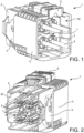
FIG. 1 is a schematic perspective view of a connector in accordance with one embodiment, essentially seen from a rear and a lateral faces; -
FIG. 2 is a schematic perspective view of the connector ofFigure 1 , essentially seen from a front and a lateral faces; -
FIG. 3 is a schematic perspective and exploded view of the connector ofFigure 2 ; -
FIG. 4 is a schematic perspective view of a cable, with a terminal and a single-wire seal mounted on the cable, as well as a retainer into which the cable is partially inserted; -
FIG. 5 is a schematic perspective view of a retainer for use with the connector ofFigures 1 to 3 ; -
FIG. 6 is a schematic perspective view of the retainer ofFigure 5 , viewed from a different angle; -
FIG. 7 is a schematic cross section of thehousing 2 of the connector ofFigures 1 to 3 ; -
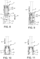
FIG. 8 is a schematic a partially semi-transparent view illustrating the insertion of a retainer into a housing cavity, the retainer being placed in front of the cavity before insertion (the housing is partially shown); -
FIG. 9 is a view similar toFigure 8 , the retainer being slightly inserted in the cavity; -
FIG. 10 is a view similar toFigures 8 and 9 , the retainer being further inserted in the cavity; -
FIG. 11 is a view similar toFigures 8 and 9 , the retainer being fully inserted in the cavity; -
FIG. 12 is a schematic perspective view of the retainer ofFigures 5 and 6 , viewed from a different angle; -
FIG.13 shows at the top and left-hand side a cavity for receiving the retainer ofFigures 5, 6 and12 , as seen from the inside it in a longitudinal section, at the bottom and left-hand side the same cavity as seen from above, and at the right-hand side a diagram corresponding to the rotational and translational phases of the movement of the retainer offigures 5, 6 and12 , as it is inserted into the cavity. - In this document, the terms "front", "rear", "inward", "outward", etc. and derivatives thereof refer to arbitrary orientations as shown on the drawings. However, it is to be understood that various alternative orientations may be used for illustrating this disclosure.
- In the drawings and in the description, same reference numbers are used for the same or similar elements.
-
FIGs. 1 to 3 illustrate an exemplary embodiment of aconnector 1. As shown onFIG. 1 , theconnector 1 comprises ahousing 2,retainers 3, a mate-assist slider 4,gear cams 5 and a CPA member 6 ("CPA" stands for Connector Position Assurance), all of them made of plastics. The function and structure of the mate-assist slider 4,gear cams 5 andCPA member 6 are known from the skilled person and are not disclosed in details in this document. - In the illustrated example, the
housing 2 comprises fourcavities 7, each configured to accommodate oneterminal 8 connected to acable 9. In the illustrated example, eachterminal 8 is anelectrical terminal 8. But this disclosure can be transposed to an optical connector accommodating optical ferules, each connected to an optical fibre. In such a case, the ferules are theterminals 8 and the optical fibres are thecables 9. - In the illustrated example, each
electrical terminal 8 is crimped onto the free end of arespective cable 9. Theterminals 8 are made of a conductive material (e.g., copper or aluminum alloy). - The
housing 2 comprises four sealing portions 10 (SeeFigure 7 ), each configured to accommodate aseal 11, thereby providing a sealing function between thehousing 2 and acable 9. In the example shown (seeFigure 4 ), theseals 11 are not crimped with theterminals 8. In an example of alternative embodiment (not shown), theterminal 8 comprises a crimping portion crimped onto a portion of theseal 11. - The
housing 2 accommodates four retainers 3 (one in each cavity 7). Eachretainer 3 is made of plastics. Eachretainer 3 is configured to retain aseal 11 in a sealingportion 10. Eachretainer 3 has aretainer body 12 configured to be inserted in thehousing 2 along an insertion direction ID up to a final position (SeeFigures 8 to 11 ). - Each
retainer body 12 has an essentially cylindrical shape (seeFigures 5 and 6 ). It extends longitudinally along a rotation axis RA, between afront end 13 and arear end 14. The rear 14 end is provided with acollar 15. In the illustrated example, advantageously, alongitudinal slot 16, parallel to the rotation axis RA, is provided in theretainer body 12 and thecollar 15 so as to insert acable 9 in the retainer 3 (SeeFigure 4 where acable 9 is partially inserted into a retainer 3). Theslot 16 is also useful to reduce the internal diameter of theretainer 3, when theretainer 3 is fastened to thehousing 2, in its final position. - The
retainer 3 comprises aninner surface 17 facing thecable 9. Theretainer body 12 comprises fourretention ribs 18 protruding from theinner surface 17. - Each
retention rib 18 extends from theinner surface 17 of theretainer 3, radially and inwardly in the collar region. Eachretention rib 18 is configured to tighten acable 9 when theretainer 3 is fastened to thehousing 2, in its final position. In other words, theretention ribs 18 ensure that the passage through theretainer 3 has a cross-section with a minimum internal diameter that is reduced in the final position of the retainer 3 (i.e., the passage through theretainer 3 may have a varying cross section and/or a varying distance between opposite internal surfaces, then said minimum internal diameter corresponds to the smallest cross-section and /or the smallest distance between opposite internal surfaces). - The
retainer body 12 comprises four clampingramps 19. In the example shown, each clampingramp 19 is positioned on theouter surface 20 of theretainer 3, opposite aretention rib 18. When theretainer 3 is inserted in thehousing 2 in its final position, the clamping ramps 19 are pushed radially towards the rotation axis RA. Thanks to theslot 16, theretainer 3 deforms (i.e., its diameter decreases) and theretention ribs 18 clamp thecable 9. In other words, theretention ribs 18 protrude on theouter surface 20 of theretainer 3 and are configured to narrow theslot 16, so as to clamp thecable 9, when theretainer 3 is inserted in thehousing 2 between an intermediate position and the final position. - The
retainer body 12 also comprises second locking means 22 configured to engage first locking means 23 located in the housing 2 (seeFigures 7 to 11 ), when theretainer 3 is in its final position, in thehousing 2. In the illustrated example, the second locking means 22 comprise a pair offlexible legs 24, each with ahook 25. Eachleg 24 extends between a joint 26 linked to theretainer body 12 towards thecollar 15 to afree end 27. In the illustrated example, eachhook 25 is positioned essentially at afree end 27 of aleg 24. Eachhook 25 extends radially outwardly from afree end 27 of aleg 24. Eachhook 25 protrudes from theouter surface 20 of theretainer body 12, when thecorresponding leg 24 is in an unstressed configuration. The twolegs 24 of aretainer 3 are symmetrical relatively to the rotation axis RA. For example, thelegs 24 are at 90° around the rotation axis RA from theslot 16. A cut-out 28 extends in theretainer body 12 around eachleg 24, except at the joint 26. Theretainer body 12 has arecess 33 behind at least a portion of eachleg 24. When theretainer 3 is inserted in thehousing 2 between the intermediate position and the final position, eachleg 24 is pushed back into therecess 33 so as to allow thehook 25 to pass the first locking means 23. - The
outer surface 20 of theretainer body 12 is provided with cam ramps 29. More particularly, in the illustrated example, there are twocam ramps 29 for eachretainer 3. Eachcam ramp 29 is positioned below ahook 25. Eachcam ramp 29 has acam surface 30 which is essentially perpendicular to theouter surface 20 of the retainer body 12 (seeFigure 6 ). Thiscam surface 30 extends over a helical portion centred on the rotation axis RA. - The
outer surface 20 is also provided with two first guiding edges 36 which are essentially parallel to the insertion direction ID. Each first guidingedge 36 comprises afirst stop portion 37 and a first guiding portion 38. Possibly, another first guidingportion 39 extends essentially parallel to the insertion direction ID on the other side of a hook 25 (seeFigure 12 ). - Each
cavity 7 also has two cam surfaces 31 (SeeFigures 7 and13 ), each configured to engage arespective cam surface 30 of theretainer 3. In other words, theretainer 3 and thehousing 2 have complementary cam means 30, 31 configured to rotate theretainer 3 with regard to the housing 2 (For example, over an angle of 112°). - Each
cavity 7 is also provided with twosecond guiding edge 40 which are essentially parallel to the insertion direction ID (Seefigure 13 ). Each second guidingedge 40 comprises asecond stop portion 41 and asecond guiding portion 42. Possibly, another second guidingportion 43 extends essentially parallel to the insertion direction ID (seeFigure 13 ). - Each
cavity 7 comprises twonotches 32. Eachnotch 32 is configured to receive ahook 25. In other words, eachnotch 32 constitutes a first locking means 23 which cooperates with the second locking means 22 (i.e., a hook 25) to hold theretainer 3 to thehousing 2. - For manufacturing a
cable connector 1, the respective free ends ofcables 9 are inserted through a longitudinal central passage of asingle wire seal 11. Then aterminal 8 is crimped onto the free end of acable 9. Eachcable 9 is inserted in aretainer 3 through itslongitudinal slot 16. Eachterminal 8 is inserted in arespective cavity 7, from therear face 34 of thehousing 2. Eachterminal 8 is accessible in itsrespective cavity 7 through an aperture in a front face 35 (i.e., a mating face 35). - The
retainer 3 is pushed towards theterminal 8. Possibly, theretainer 3 pushes thesingle wire seal 11 in the same direction (Figure 8 ). Theretainer 3 is positioned in front of acavity 7, regardless of the angular orientation of theretainer 3 to thehousing 2, about the rotation axis RA. Theretainer 3 is slightly inserted in acavity 7 up to a position where the respective cam surfaces 30, 31 of theretainer 3 and thehousing 2 engage each other (SeeFigure 9 ). For example, taking the corner between each guidingedge 36 and therespective cam surface 20 as a reference, this reference may be placed in front of the cam surfaces 31 at a point A, B, etc. (seeFigure 13 ). Thanks to the cam surfaces 30, 31, as theretainer 3 is further pushed and inserted in itscavity 7, it rotates about the rotation axis RA, up to an intermediate position, where the first 23 and second 22 locking means are aligned in a direction parallel to the insertion direction ID (i.e., the rotation axis RA). In the intermediate position, the reference (i.e., the corner between each guidingedge 36 and the respective cam surface 20) is at a point O (seeFigure 13 ). When theretainer 3 is in this rotational position (SeeFigures 10 ,13 ), the cam surfaces 30, 31 are no longer facing each other. Theretainer 3 is in the intermediate position. Theretainer 3 does no longer rotate when pushed into thehousing 2, because thefirst stop portion 37 of theretainer 3 abuts against thesecond stop portion 41 of thehousing 2. Then, theretainer 3 only slides into thehousing 2 along the insertion direction ID, while being guided by the first 36 and second 40 guiding edges. - As the first 23 and second 22 locking means are aligned parallel to the insertion direction ID and as the
retainer 3 is further pushed in itscavity 7, eachhook 25 andleg 24 are pushed inwardly in therecess 33, up to the final position of theretainer 3 in thehousing 2, where eachleg 24 resiliently returns to an unstressed configuration with ahook 25 behind anotch 32. In other words, in the final position of theretainer 3, the first locking means 23 engage the second locking means, thereby holding theretainer 3 to thehousing 2.
Claims (11)
- Cable connector (1) comprisinga housing (2) having at least one cavity (7) configured to accommodate at least one cable (9) terminal (8) connected to a cable (9), a sealing portion (10) configured to accommodate a seal (11) providing a sealing function between the housing (2) and the cable (9), and first locking means (23),a retainer (3), having a retainer body (12) configured to be inserted in the housing (2) along an insertion direction (ID) up to a final position, the retainer (3) being configured to retain the seal (11) in the sealing portion (10), and the retainer (3) having second locking means (22) configured to engage the first locking means (23) when the retainer (3) is in the final position and thereby hold the retainer (3) to the housing (2), characterized in that the retainer (3) and the housing (2) have complementary cam means (30, 31) configured to rotate the retainer (3) relative to the housing (2), if the first and second locking means (22) are misaligned, when the retainer (3) is inserted in the housing (2), toward an intermediate position of the retainer (3), where the first (23) and second (22) locking means are aligned parallel to the insertion direction (ID).
- Cable connector (1) according to claim 1, wherein the retainer (3) and the housing (3) have complementary guiding means configured to prevent the retainer (3) in the intermediate position from rotating relative to the housing (2) and to guide a translation of the retainer (3) parallel to the insertion direction (ID), from the intermediate position to a final position.
- Cable connector (1) according to claim 1 or 2, wherein the retainer (3) comprises a slot (16) extending longitudinally parallel to the insertion direction (ID) and an outer surface (20), at least one clamping ramp (19) protruding on the outer surface (20) and being configured to narrow the slot (16), so that the retainer (3) clamps the cable (9), when the retainer (3) is inserted in the housing (2) between the intermediate position and the final position.
- Cable connector (1) according to any preceding claim, wherein the retainer (3) further comprises an inner surface (17) facing the cable (9), and at least one retention rib (18) protruding from the inner surface (17).
- Cable connector (1) according to any preceding claim, wherein the second locking means (22) comprises a flexible leg (24) extending between the retainer body (12) and a hook (25), the retainer body (12) having a recess (33) behind at least a portion of the leg (24), wherein the leg (24) is pushed back when the retainer (3) is inserted in the housing (2) between the intermediate position and the final position, so as to allow the hook (25) to pass the first locking means (23).
- Cable connector (1) according to any preceding claim, wherein the terminal (8) comprises a crimping portion crimped over a portion of the seal (11).
- Cable connector (1) according to any of claims 1 to 5, wherein the seal (11) is not attached to the terminal (8).
- Cable connector (1) according to any preceding claim, wherein the terminal (8) is an electrical terminal (8).
- A method for manufacturing a cable connector (1) comprising the following steps:providing a housing (2) having a mating face (35), a rear face (34), a cavity (7) between the mating face (35) and the rear face (34), and first locking means (23),providing a retainer (3) having second locking means (22),inserting a cable free end in a passage made through a seal (11),inserting the cable (9) in a passage made through the retainer (3),connecting the cable (9) to a terminal (8),inserting said terminal (8) connected to the cable (9) in the cavity (7) from the rear face (34),pushing the retainer (3) through the rear face (34) parallel to an insertion direction (ID), characterized in that the retainer (3) and the housing (2) have complementary cam means (30, 31) configured to rotate the retainer (3) with regard to the housing (2) if the first (23) and second (22) locking means are misaligned, so that performing step (g) up to an intermediate position of the retainer (3) in the housing (2) causes the first (23) and second (22) locking means to be aligned parallel to the insertion direction (ID).
- A method according to claim 9, comprising a step (h) of pushing the retainer (3) through the rear face (34) parallel to the insertion direction (ID) up to a final position where the first locking means (23) engage the second locking means (22), thereby holding the retainer (3) to the housing (2).
- A method according to claim 10, wherein the passage through the retainer (3) has a cross-section with a minimum internal diameter and performing step (h) causes the minimum internal diameter of the passage through the retainer (3) to decrease, so that the retainer (3) clamps the cable (9).
Priority Applications (1)
| Application Number | Priority Date | Filing Date | Title |
|---|---|---|---|
| EP23174975.5A EP4468528A1 (en) | 2023-05-23 | 2023-05-23 | Sealed connector having a retainer with strain relief means |
Applications Claiming Priority (1)
| Application Number | Priority Date | Filing Date | Title |
|---|---|---|---|
| EP23174975.5A EP4468528A1 (en) | 2023-05-23 | 2023-05-23 | Sealed connector having a retainer with strain relief means |
Publications (1)
| Publication Number | Publication Date |
|---|---|
| EP4468528A1 true EP4468528A1 (en) | 2024-11-27 |
Family
ID=86497549
Family Applications (1)
| Application Number | Title | Priority Date | Filing Date |
|---|---|---|---|
| EP23174975.5A Pending EP4468528A1 (en) | 2023-05-23 | 2023-05-23 | Sealed connector having a retainer with strain relief means |
Country Status (1)
| Country | Link |
|---|---|
| EP (1) | EP4468528A1 (en) |
Citations (5)
| Publication number | Priority date | Publication date | Assignee | Title |
|---|---|---|---|---|
| US5857864A (en) * | 1996-02-28 | 1999-01-12 | Yazaki Corporation | Waterproof connector with guide portion for aligning connector during engagement |
| GB2469023A (en) * | 2009-03-30 | 2010-10-06 | Tyco Electronics | Method of assembling coaxial connector |
| US20110315442A1 (en) * | 2009-01-23 | 2011-12-29 | Weidmueller Interface Gmbh & Co. Kg | Fixing device for fixing a cable at a housing feed-through |
| EP2930795A1 (en) * | 2014-04-09 | 2015-10-14 | Delphi Technologies, Inc. | Sealed connector with an extended seal sleeve and an anti-water pooling retainer |
| EP3220487A1 (en) * | 2016-03-17 | 2017-09-20 | TE Connectivity Germany GmbH | Connector device for a waterproof connector, waterproof connector as well as assembled cable |
-
2023
- 2023-05-23 EP EP23174975.5A patent/EP4468528A1/en active Pending
Patent Citations (5)
| Publication number | Priority date | Publication date | Assignee | Title |
|---|---|---|---|---|
| US5857864A (en) * | 1996-02-28 | 1999-01-12 | Yazaki Corporation | Waterproof connector with guide portion for aligning connector during engagement |
| US20110315442A1 (en) * | 2009-01-23 | 2011-12-29 | Weidmueller Interface Gmbh & Co. Kg | Fixing device for fixing a cable at a housing feed-through |
| GB2469023A (en) * | 2009-03-30 | 2010-10-06 | Tyco Electronics | Method of assembling coaxial connector |
| EP2930795A1 (en) * | 2014-04-09 | 2015-10-14 | Delphi Technologies, Inc. | Sealed connector with an extended seal sleeve and an anti-water pooling retainer |
| EP3220487A1 (en) * | 2016-03-17 | 2017-09-20 | TE Connectivity Germany GmbH | Connector device for a waterproof connector, waterproof connector as well as assembled cable |
Similar Documents
| Publication | Publication Date | Title |
|---|---|---|
| EP2686919B1 (en) | High voltage connector assembly | |
| EP1528637B1 (en) | Cable connector having a retainer for retaining the contact and clamping the cable | |
| US6361348B1 (en) | Right angle, snap on coaxial electrical connector | |
| US7507125B2 (en) | Connector and device equipped with the same | |
| US4801277A (en) | Underwater electrical connector with keyed insert sleeve | |
| EP0760540B1 (en) | Electrical connector with improved terminal positioning means | |
| US7588446B2 (en) | Connector and a connector assembly | |
| EP2337157B1 (en) | Connector | |
| US20090081908A1 (en) | Connector With Redundant Terminal Locking | |
| EP0959532A1 (en) | A lever type connector | |
| CN108463925A (en) | Connector | |
| US10535951B2 (en) | Plug connector and method for producing a plug connection | |
| US6461177B1 (en) | Electrical connector | |
| CN107534256A (en) | Joint connector | |
| US7029303B2 (en) | Hermaphroditic handle socket assembly and pin assembly | |
| US4641899A (en) | Multi-part electrical connector assembly | |
| US12500366B2 (en) | Electrical plug connector and method for assembling an electrical plug connector | |
| US20250385465A1 (en) | Cable connector with alignment-dependent locking mechanism and flexible protrusion for cable retention | |
| EP4468530A1 (en) | Sealed connector with a retainer integrated to the housing | |
| CN113224581A (en) | Lever type connector | |
| WO2007009487A1 (en) | Male electrical terminal | |
| EP3866277A1 (en) | Angled connector with a module sliding along a curved path | |
| US11557853B2 (en) | Connector assembly with strain relief device in two parts | |
| JP6688670B2 (en) | Connector assembly method and connector | |
| EP4462610A1 (en) | Electrical power connector and method for unmating the same |
Legal Events
| Date | Code | Title | Description |
|---|---|---|---|
| PUAI | Public reference made under article 153(3) epc to a published international application that has entered the european phase |
Free format text: ORIGINAL CODE: 0009012 |
|
| STAA | Information on the status of an ep patent application or granted ep patent |
Free format text: STATUS: THE APPLICATION HAS BEEN PUBLISHED |
|
| AK | Designated contracting states |
Kind code of ref document: A1 Designated state(s): AL AT BE BG CH CY CZ DE DK EE ES FI FR GB GR HR HU IE IS IT LI LT LU LV MC ME MK MT NL NO PL PT RO RS SE SI SK SM TR |
|
| STAA | Information on the status of an ep patent application or granted ep patent |
Free format text: STATUS: REQUEST FOR EXAMINATION WAS MADE |
|
| 17P | Request for examination filed |
Effective date: 20250522 |