EP4468522A1 - Connector - Google Patents
Connector Download PDFInfo
- Publication number
- EP4468522A1 EP4468522A1 EP24166541.3A EP24166541A EP4468522A1 EP 4468522 A1 EP4468522 A1 EP 4468522A1 EP 24166541 A EP24166541 A EP 24166541A EP 4468522 A1 EP4468522 A1 EP 4468522A1
- Authority
- EP
- European Patent Office
- Prior art keywords
- locator
- connector
- hole
- shell
- portions
- Prior art date
- Legal status (The legal status is an assumption and is not a legal conclusion. Google has not performed a legal analysis and makes no representation as to the accuracy of the status listed.)
- Granted
Links
Images








Classifications
-
- H—ELECTRICITY
- H01—ELECTRIC ELEMENTS
- H01R—ELECTRICALLY-CONDUCTIVE CONNECTIONS; STRUCTURAL ASSOCIATIONS OF A PLURALITY OF MUTUALLY-INSULATED ELECTRICAL CONNECTING ELEMENTS; COUPLING DEVICES; CURRENT COLLECTORS
- H01R4/00—Electrically-conductive connections between two or more conductive members in direct contact, i.e. touching one another; Means for effecting or maintaining such contact; Electrically-conductive connections having two or more spaced connecting locations for conductors and using contact members penetrating insulation
- H01R4/24—Connections using contact members penetrating or cutting insulation or cable strands
- H01R4/2416—Connections using contact members penetrating or cutting insulation or cable strands the contact members having insulation-cutting edges, e.g. of tuning fork type
- H01R4/242—Connections using contact members penetrating or cutting insulation or cable strands the contact members having insulation-cutting edges, e.g. of tuning fork type the contact members being plates having a single slot
- H01R4/2425—Flat plates, e.g. multi-layered flat plates
- H01R4/2429—Flat plates, e.g. multi-layered flat plates mounted in an insulating base
- H01R4/2433—Flat plates, e.g. multi-layered flat plates mounted in an insulating base one part of the base being movable to push the cable into the slot
-
- H—ELECTRICITY
- H01—ELECTRIC ELEMENTS
- H01R—ELECTRICALLY-CONDUCTIVE CONNECTIONS; STRUCTURAL ASSOCIATIONS OF A PLURALITY OF MUTUALLY-INSULATED ELECTRICAL CONNECTING ELEMENTS; COUPLING DEVICES; CURRENT COLLECTORS
- H01R4/00—Electrically-conductive connections between two or more conductive members in direct contact, i.e. touching one another; Means for effecting or maintaining such contact; Electrically-conductive connections having two or more spaced connecting locations for conductors and using contact members penetrating insulation
- H01R4/24—Connections using contact members penetrating or cutting insulation or cable strands
- H01R4/2416—Connections using contact members penetrating or cutting insulation or cable strands the contact members having insulation-cutting edges, e.g. of tuning fork type
- H01R4/242—Connections using contact members penetrating or cutting insulation or cable strands the contact members having insulation-cutting edges, e.g. of tuning fork type the contact members being plates having a single slot
- H01R4/2425—Flat plates, e.g. multi-layered flat plates
- H01R4/2429—Flat plates, e.g. multi-layered flat plates mounted in an insulating base
-
- H—ELECTRICITY
- H01—ELECTRIC ELEMENTS
- H01R—ELECTRICALLY-CONDUCTIVE CONNECTIONS; STRUCTURAL ASSOCIATIONS OF A PLURALITY OF MUTUALLY-INSULATED ELECTRICAL CONNECTING ELEMENTS; COUPLING DEVICES; CURRENT COLLECTORS
- H01R13/00—Details of coupling devices of the kinds covered by groups H01R12/70 or H01R24/00 - H01R33/00
- H01R13/62—Means for facilitating engagement or disengagement of coupling parts or for holding them in engagement
- H01R13/629—Additional means for facilitating engagement or disengagement of coupling parts, e.g. aligning or guiding means, levers, gas pressure electrical locking indicators, manufacturing tolerances
- H01R13/631—Additional means for facilitating engagement or disengagement of coupling parts, e.g. aligning or guiding means, levers, gas pressure electrical locking indicators, manufacturing tolerances for engagement only
-
- H—ELECTRICITY
- H01—ELECTRIC ELEMENTS
- H01R—ELECTRICALLY-CONDUCTIVE CONNECTIONS; STRUCTURAL ASSOCIATIONS OF A PLURALITY OF MUTUALLY-INSULATED ELECTRICAL CONNECTING ELEMENTS; COUPLING DEVICES; CURRENT COLLECTORS
- H01R13/00—Details of coupling devices of the kinds covered by groups H01R12/70 or H01R24/00 - H01R33/00
- H01R13/02—Contact members
Definitions
- This invention relates to a connector which connects cables to each other.
- Patent Document 1 JPA2006-236855 discloses a connector for insulation displacement connection.
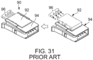
- a connector 90 of Patent Document 1 is provided with an electric wire holding block (or a locator) 92 and a contact block (or a housing) 94.
- the contact block 94 holds insulation displacement connection terminals (not shown) which protrude into a receiving portion (not shown) which receives the electric wire holding block 92.
- the electric wire holding block 92 is formed with holding holes (not shown) which hold electric wires 96, respectively, and receiving grooves (not shown) which receive the insulation displacement connection terminals.
- the connector 90 of Patent Document 1 is provided with the electric wire holding block or locator 92.
- the electric wire holding block 92 By using the electric wire holding block 92, a connection process for connecting the electric wires 96 to the insulation displacement connection terminals (not shown) of the connector 90 can be easily carried out. There is a demand to realize easiness of such connection process also in a connection process for connecting electric wires to each other.
- the connector comprises a housing, at least one terminal, a shell and at least one locator.
- Each of the cables comprises at least one electric wire.
- the terminal has at least two connection portions.
- the connection portions are respectively connected to the electric wires of the cables.
- the shell has two shell sidewall portions which are apart from each other in a width direction.
- Each of the shell sidewall portions is provided with at least one set of a first hole and a second hole corresponding to the locator. The first hole and the second hole of the one set pierce the shell sidewall portion in the width direction and are apart from each other in a first direction perpendicular to the width direction.
- the locator is attached to the shell so that the locator is movable from a first position to a second position in the first direction.
- the locator corresponds to at least one of the cables and to the connection portion connected to the electric wire of the cable corresponding thereto.
- the locator is provided with a first end face, a second end face, a receiving hole, an admitting portion and two protrusions.
- the first end face and the second end face are located at both ends of the locator in a second direction, which is perpendicular to the width direction and intersects with the first direction.
- the receiving hole pierces the locator from the second end face to the first end face and is receivable an end of the electric wire of the cable corresponding to the locator.
- the admitting portion communicates with the receiving hole and allows the connection portion corresponding to the locator to be moved when the locator is moved.
- the protrusions correspond to the shell sidewall portions, respectively. Each of the protrusions protrudes outward in the width direction. When the locator is positioned at the first position, each of the protrusions is positioned in the first hole corresponding to the locator. When the locator is positioned at the second position, each of the protrusions is positioned in the second hole corresponding to the locator, and the connection portion corresponding to the locator is in the receiving hole in part.
- the connector according to the above-mentioned aspect of this invention can easily connect the electric wire to the terminal with simple structure using the at least one locator attached to the shell thereof. Accordingly, it can be improved to handle the electric wires in connection therebetween.
- a connector 10 is for connecting cables 50 to one another.
- the connector 10 connects three cables 50 to one another.
- the connector 10 of the present invention may connect two cables 50 to each other or connect four or more cables 50 to one another.
- each of the cables 50 is a twisted pair cable provided with two electric wires 501, i.e. 501A and 501B. Moreover, in the present embodiment, each of the cables 50 has a shielding conductor 503. In other words, in the present embodiment, each of the cables 50 is a shielded twisted pair (STP) cable. In the present embodiment, the shielding conductor 503 is folded back at an end portion thereof. However, the present invention is not limited thereto.
- Each of the cables 50 may be an unshielded twisted pair (UTP) cable.
- Each of the cables 50 should be provided with at least one electric wire 501, and the connector 10 may be formed according to the number of the at least one electric wire 501.
- the present invention is applicable to a connector for connecting coaxial cables to each other.
- the connector 10 is provided with a housing 12, at least one terminal 14, a shell 16 and at least one locator 18.
- the housing 12 consists of two parts, i.e., an upper housing 121 and a lower housing 123.
- an up-down direction is a Z-direction.
- the housing 12 may consist of a single part.
- the at least one terminal 14 is two in number.
- the number of the terminals 14 correspond to the number of the electric wires 501 included in each of the cables 50 (see Fig. 2 ).
- the connector 10 is provided with the two terminals 14, i.e., a first terminal 14A and a second terminal 14B, which respectively correspond to the two electric wires 501, i.e. 501A and 501B, of each of the cables 50.
- the two terminals 14 have shapes symmetrical to each other with respect to a plane perpendicular to a width direction and are arranged so that they are apart from each other in the width direction. In the present embodiment, the width direction is an X-direction.
- the two terminals 14 have the shapes symmetrical to each other, so that they have signal transmission path lengths equal to each other and transmission characteristics same as each other.
- the shell 16 has two shell sidewall portions 161, i.e. 161R and 161L, which are apart from each other in the width direction and two coupling wall portions 163 which couple the shell sidewall portions 161 to each other.
- the shell 16 further has a bottom plate portion 165 covering a bottom of the shell 16 in part.
- the shell 16 is formed of a conductive metal sheet.
- the shell 16 may be made of resin. Nevertheless, it is preferable that the shell 16 is made of conductive metal in consideration of strength thereof and an electromagnetic shield effect thereof.
- the at least one locator 18 is three in number.
- the locators 18 correspond to the cables 50, respectively.
- first, second and third locators 18-1, 18-2 and 18-3 correspond to first, second and third cables 50-1, 50-2 and 50-3, respectively.
- the present invention is not limited thereto.
- the number of the locators 18 may be fewer than the number of the cables 50.
- the connector 10 may have one locator 18 corresponding to any one of the electric wires 501.
- one locator 18 may correspond to two or more cables 50. Nevertheless, that the locators 18 correspond to the cables 50 in a one-to-one relationship provides better operability.
- the connector 10 further has an upper cover portion (a cover portion) 20, a lower cover portion 22, two fixing blocks 24 and a plurality of screws 26.
- the upper cover portion 20 is made of metal and provided with two cover sidewall portions 201, a coupling portion 203 and two attaching portions 205.
- the cover sidewall portions 201 are arranged apart from each other in the width direction.
- the coupling portion 203 couples the cover sidewall portions 201 to each other.
- the lower cover portion 22 is made of metal and provided with two cover sidewall portions 221 and a coupling portion 223.
- the cover sidewall portions 221 are arranged apart from each other in the width direction.
- the coupling portion 223 couples the cover sidewall portions 221 to each other.
- the cover portion 20, the fixing blocks 24 and the screws 26 are not essential. However, these hold the cables 50 (see Fig. 1 ) and cause an electromagnetic shield effect.
- the terminal 14A has a first portion 141 having a plate-like shape, a second portion 143 having a plate-like shape and a coupling portion 145 coupling the first portion 141 and the second portion 143 to each other.
- the second terminal 14B has a shape symmetrical to that of the terminal 14A.
- the first portion 141 and the second portion 143 of the terminal 14A extend in a first direction perpendicular to the width direction.
- the first portion 141 and the second portion 143 are arranged apart from each other in a second direction, which is perpendicular to the width direction and intersects with the first direction, and arranged in parallel to each other.
- the coupling portion 145 couples one end portion of the first portion 141 to a middle portion of the second portion 143.
- the first direction is the Z-direction which is identical with the up-down direction.
- the first direction may be inclined to the up-down direction.
- the second direction is a Y-direction perpendicular to the first direction.
- connection portions 147 i.e., first, second and third connection portions 147-1, 147-2 and 147-3.
- the first connection portion 147-1 and the second connection portion 147-2 are arranged so that their projections are identical to each other in the second direction.
- the second connection portion 147-2 and the third connection portion 147-3 have shapes symmetrical to each other in the first direction.
- connection portions 147 respectively correspond to the cables 50. Moreover, each of the connection portions 147 of the first terminal 14A respectively correspond to the electric wire 501A which is one of the electric wires 501 of the cable 50 corresponding thereto. Thus, the connection portions 147-1, 147-2 and 147-3 of the first terminal 14A are respectively connected to the electric wires 501A of the cables 50-1, 50-2 and 50-3 which are different from one another.
- each of the connection portions 147 is an insulation displacement connection piece having a bifurcate shape and extending in the first direction. However, the present invention is not limited thereto.
- the shape of the terminal 14 and the shape of the connection portion 147 are not specifically limited.
- the number of the connection portions 147 of the terminal 14 depends on the number of the cables 50.
- the terminal 14 should have at least two connection portions 147.
- the base portion 125 of the upper housing 121 is formed with a plurality of through holes 131 piercing it in the up-down direction.
- the through holes 131 are four in number.
- the through holes 131 correspond to the connection portions 147 of the terminals 14, respectively.
- the through holes 131 of the upper housing 121 respectively correspond to the first connection portion 147-1 of the first terminal 14A, the second connection portion 147-2 of the first terminal 14A, the first connection portion 147-1 of the second terminal 14B and the second connection portion 147-2 of the second terminal 14B.
- Each of the through holes 131 has a size into which the connection portion 147 is insertable.
- the middle wall 127 of the upper housing 121 has at least one receiving surface 135.
- the upper housing 121 has four receiving surfaces 135.
- Each of the receiving surfaces 135 corresponds to any one of the electric wires 501 of the cables 50.
- the receiving surfaces 135 are bottom surfaces of grooves 137 formed in the middle wall 127.
- Each of the grooves 137 is depressed toward the middle of the middle wall 127 in the front-rear direction and extends in the first direction.
- the bottom surfaces of the grooves 137 intersect with the second direction.
- Two of the receiving surfaces 135 are directed forward.
- the remaining two of the receiving surfaces 135 are directed rearward.
- the receiving surfaces 135 correspond to the through holes 131, respectively.
- Each of the receiving surfaces 135 is aligned with the through hole 131 corresponding thereto in the front-rear direction.
- the upper housing 121 and the lower housing 123 partly sandwich the terminals 14 and hold them.
- Each of the connection portions 147 of the terminals 14 passes through the through hole 131 corresponding thereto and is exposed outside.
- the main portion 181 of the first locator 18-1 is provided with a first end face 187 and a second end face 189.
- the first end face 187 and the second end face 189 are located at both ends of the first locator 18-1 in the second direction.
- the main portion 181 of the first locator 18-1 is further formed with at least one receiving hole 191 and at least one admitting portion 193.
- the first locator 18-1 is formed with two receiving holes 191R and 191L and two admitting portions 193R and 193L.
- the receiving holes 191R and 191L correspond to the admitting portions 193R and 193L, respectively.
- the receiving holes 191R and 191L of the first locator 18-1 respectively correspond to the electric wires 501A and 501B of the first cable 50-1 corresponding to the first locator 18-1.
- Each of the receiving holes 191R and 191L pierces the first locator 18-1 from the second end face 189 to the first end face 187, so that it can receive an end portion of the electric wire 501A or 501B corresponding thereto.
- each of the receiving holes 191R and 191L has a size which can receive the end portion of the electric wire 501A or 501B.
- the admitting portions 193R and 193L of the first locator 18-1 correspond to the terminals 14A and 14B, respectively.
- the admitting portions 193R and 193L respectively correspond to the first connection portion 147-1 of the first terminal 14A and the first connection portion 147-1 of the second terminal 14B, which are connected to the electric wire 501A and 501B of the first cable 50-1 corresponding to the first locator 18-1.
- each of the admitting portions 193R and 193L has a size which allows the connection portion 147 corresponding thereto to be moved in the first direction.
- each of the admitting portions 193R and 193L communicates with the receiving hole 191R or 191L corresponding thereto.
- the first locator 18-1 is further provided with two auxiliary protrusions 197, i.e. 197R and 197L.
- the auxiliary protrusions 197R and 197L are provided to the auxiliary portions 185R and 185L, respectively.
- the auxiliary protrusions 197R and 197I protrude outward in the width direction.
- the auxiliary protrusions 197R and 197L are respectively located rearward of the protrusions 195 in the front-rear direction.
- the auxiliary protrusions 197R and 197L are located at positions slightly nearer to the main portion 181 than the protrusions 195R and 195L in the first direction.
- each of a second locator 18-2 and a third locator 18-3 is formed so that it is identical to the first locator 18-1.
- the admitting portions 193R and 193L of the second locator 18-2 respectively correspond to the second connection portion 147-2 of the first terminal 14A and the second connection portion 147-2 of the second terminal 14B which are connected to the electric wires 501A and 501B of the second cable 50-2 corresponding to the second locator 18-2.
- the admitting portions 193R and 193L of the third locator 18-3 respectively correspond to the third connection portion 147-3 of the first terminal 14A and the third connection portion 147-3 of the second terminal 14B which are connected to the electric wires 501A and 501B of the third cable 50-3 corresponding to the third locator 18-3.
- each of the shell sidewall portions 161R and 161L of the shell 16 is provided with at least one set of a first hole 171 and a second hole 173, wherein the at least one set of the first hole 171 and the second hole 173 correspond to the at least one locator 18.
- each of the shell sidewall portions 161R and 161L is provided with three sets of the first holes 171, i.e. 171-1, 171-2 and 171-3, and the second holes 173, i.e. 173-1, 173-2 and 173-3.
- the first hole 171-1 and the second hole 173-1 correspond to the first locator 18-1.
- the first hole 171-2 and the second hole 173-2 correspond to the second locator 18-2.
- the first hole 171-3 and the second hole 173-3 correspond to the third locator 18-3.
- each of the first holes 171, i.e. 171-1, 171-2 and 171-3, and the second holes 173, i.e. 173-1, 173-2 and 173-3 pierces the shell sidewall portion 161R or 161L in the width direction.
- the first hole 171 and the second hole 173 are located apart from each other in the first direction.
- each of the third holes 175, i.e. 175-1, 175-2 and 175-3, and the fourth holes 177 i.e.
- the third hole 175 and the fourth hole 177 are located apart from each other in the first direction.
- the first hole 171 and the second hole 173 correspond to the protrusions 195R or 195L of the locator 18 corresponding thereto.
- the third hole 175 and the fourth hole 177 correspond to the auxiliary protrusions 197R or 197L of the locator 18 corresponding thereto.
- the first end face 187 of each of the second locator 18-2 and the third locator 18-3 is directed forward in the front-rear direction while the second end face 189 of each of the second locator 18-2 and the third locator 18-3 is directed rearward in the front-rear direction.
- the description for the first locator 18-1 is applicable to the second locator 18-2 and the third locator 18-3 with the necessary modification.
- the description for the second locator 18-2 is applicable to the first locator 18-1 and the third locator 18-3 with the necessary modification.
- a size of the main portion 181 of the first locator 18-1 is slightly smaller than an internal size of the shell 16 in the width direction.
- a total size of the locator 18 with the protrusions 195 i.e. 195R and 195L, is larger than the internal size of the shell 16 in the width direction.
- attachment of the locator 18 to the shell 16 is carried out by pressing the locator 18 toward the accommodation portion 167 corresponding thereto along the first direction.
- a size of the protrusion 195 i.e. 195R or 195L, is reduced toward a tip thereof. Because of the shape of the protrusion 195, the attachment of the locator 18 to the shell 16 can be easily carried out.
- the protrusions 195 can enter the accommodation portions 167 mainly owing to resilient deformation of the support portions 183, and the auxiliary protrusions 197 can enter the accommodation portions 167 mainly owing to resilient deformation of the shell 16.
- each of the receiving surfaces 135 is visible through each of the receiving holes 191, i.e. 191R and 191L, thereof.
- the first locator 18-1 is positioned at the first position, a part of a region occupied by each of the receiving holes 191 is included in a region occupied by the receiving surface 135 corresponding thereto in the first direction while a remaining part of the region occupied by the receiving hole 191 is out of the region occupied by the receiving surface 135 in the first direction.
- the connection portion 147 (see Fig. 13 ) corresponding to each of the receiving holes 191 is not visible in the receiving hole 191.
- each of the receiving holes 191 allows the end portion of the electric wire 501 corresponding thereto to be inserted therein and a tip of the electric wire 501 to be brought into abutment with the receiving surface 135.
- the tip of the electric wire 501 inserted into the receiving hole 191 can be brought into abutment with the receiving surface 135.
- the second locator 18-2 is positioned at the first position, and the electric wires 501, i.e. 501R and 501L, are inserted into the receiving holes 191, i.e. 191R and 191L, of the second locator 18-2, respectively.
- the electric wires 501 i.e. 501R and 501L
- the receiving holes 191, i.e. 191R and 191L are inserted into the receiving holes 191, i.e. 191R and 191L, of the second locator 18-2, respectively.
- Fig. 11 when the second locator 18-2 is attached to the shell 16, a gap remains between the first end face 187 of the second locator 18-2 and each of the receiving surfaces 135 of the upper housing 121 in the second direction. Accordingly, as shown in Fig.
- the tips of the electric wires 501 of the second cable 50-2 are visible when viewed along the first direction, wherein the electric wires 501 are inserted in the receiving holes 191 of the second locator 18-2.
- the tips of the electric wires 501 of the second cable 50-2 are brought into abutment with the receiving surfaces 135 or not, wherein the electric wires 501 are inserted in the receiving holes 191 of the second locator 18-2.
- the size of the protrusion 195 in the width direction is reduced toward the tip thereof.
- the protrusion 195 when the locator 18 receives a force directed into the accommodation portion 167, the protrusion 195 positioned in the first hole 171 can easily come out from the first hole 171.
- the locator 18 receives a force directed outward of the accommodation portion 167 coming out of the protrusion 195 positioned in the first hole 171 from the first hole 171 is regulated.
- the protrusions 195 prevent the locator 18 attached to the shell 16 from falling away from the shell 16.
- the auxiliary protrusion 197 is set in shape and in size so that it cannot come out from the third hole 175 when the locator 18 receives a relatively small force and so that it can come out from the third hole 175 when the locator 18 receives a relatively large force. It also depends on a shape and a position of the protrusion 195 whether the auxiliary protrusion 197 can come out from the third hole 175 or not.
- a position of the locator 18 with respect to the shell 16 is referred to as a second position when the protrusions 195 are positioned in the second holes 173 while the auxiliary protrusions 197 are positioned in the fourth holes 177.
- each of the protrusions 195 is positioned in the second hole 173 corresponding to the locator 18 while each of the auxiliary protrusions 197 is positioned in the fourth hole 177.
- the locator 18 is attached to the shell 16 so that the locator 18 is movable from the first position to the second position in the first direction.
- connection portion 147 is partly visible in the receiving hole 191.
- the connection portions 147 correspond to the locator 18 are partly located in the receiving holes 191.
- the electric wires 501 can be connected to the connection portions 147 as shown in Fig. 18 by inserting, into the receiving holes 191 of the locator 18 positioned at the first position, the end portions of the electric wires 501 corresponding thereto and then by moving the locator 18 from the first position to the second position.
- the locators 18-1, 18-2 and 18-3 are positioned at the second positions, respectively.
- the coupling portion 203 of the upper cover portion 20 has an approximately rectangular shape and a size which allows the coupling portion 203 to cover the shell 16 when viewed along the up-down direction.
- the cover sidewall portions 201 have approximately rectangular shapes long in the front-rear direction and extend downward in the up-down direction from both edges of the coupling portion 203.
- Each of the cover sidewall portions 201 has spring pieces 207 protruding inward in the width direction.
- each of the cover sidewall portions 201 has two spring pieces 207.
- the spring pieces 207 respectively correspond to the first holes 171-1 and 171-2, which correspond to the first locator 18-1 and the second locator 18-2, of the shell 16.
- the attaching portions 205 adjoin a front portion and a rear portion of the coupling portion 203, respectively.
- Each of the attaching portions 205 is formed with screw holes 209 piercing it in the up-down direction.
- the upper cover portion 20 is attached to the shell 16 in a state that the first locator 18-1 and the second locator 18-2 are positioned at the second positions.
- the cover sidewall portions 201 are positioned outward of the shell sidewall portions 161R and 161L in the width direction.
- Each of the spring pieces 207 is positioned in the first hole 171 corresponding thereto when the upper cover portion 20 is attached to the shell 16.
- any or all of the spring pieces 207 cannot enter the first holes 171 corresponding thereto. Accordingly, the upper cover portion 20 cannot be attached to the shell 16.
- the upper cover portion 20 is fixed to the fixing blocks 24 with the screws 26.
- the cables 50-1 and 50-2 are sandwiched and fixed between the attaching portions 205 and the fixing blocks 24, respectively.
- the electric wires 501 of the cables 50-1 and 50-2 are prevented from coming off from the connector 10.
- the shielding conductors 503 of the cables 50 are electrically connected to the upper cover portion 20 so that an electromagnetic shield effect is improved.
- the lower cover portion 22 has the two cover sidewall portions 221, the coupling portion 223 and an attaching portion 225.
- the lower cover portion 22 is made of metal.
- the coupling portion 223 has an approximately rectangular shape and a size which covers a half of the shell 16.
- the cover sidewall portions 221 extend upward in the up-down direction from both edges of the coupling portion 223.
- Each of the cover sidewall portions 221 has spring pieces 227 protruding inward in the width direction.
- each of the cover sidewall portions 221 has two spring pieces 227.
- the spring pieces 227 respectively correspond to the first hole 171-3 and the third hole 175-3, which correspond to the third locator 18-3, of the shell 16.
- the attaching portion 225 adjoins a rear portion of the coupling portion 223.
- the attaching portion 225 is formed with screw holes 229 piercing it in the up-down direction.
- the lower cover portion 22 is attached to the shell 16 in a state that the third locator 18-3 is positioned at the second position.
- the cover sidewall portions 221 are positioned outward of the shell sidewall portions 161R and 161L in the width direction.
- the spring pieces 227 are respectively positioned in the first hole 171-3 and the third hole 175-3 which correspond to them.
- the third locator 18-3 is positioned at the first position, the spring pieces 227 cannot enter the first hole 171-3 and the third hole 175-3 corresponding to them. Accordingly, the lower cover portion 22 cannot be attached to the shell 16.
- the lower cover portion 22 is fixed to one of the fixing blocks 24 with the screws 26.
- the cable 50-3 is sandwiched between the lower cover portion 22 of the fixing block 24.
- the electric wires 501 of the cable 50-3 are prevented from coming off from the connector 10.
- the shielding conductor 503 of the cable 50-3 is electrically connected to the lower cover portion 22, so that an electromagnetic shield effect is improved.
- the use of the connector 10 according to the present embodiment enables mutual connection of the cables 50 with simple operation.
- the gaps are provided between the first end face 187 of the locator 18 and the receiving surfaces 135 of the housing 12 in the second direction, and the gaps are made visible from outside. Accordingly, connections of the electric wires 501 of the cable 50 to the connector 10 can be surely carried out.
- the connector 10 according to the present embodiment can be used as a branch connector which divides a transmission line, a signal transmission path or a power supply line into two.
- a conventional branch connector takes a form of hanging a branch line from a main line. Accordingly, it is necessary to secure some length of the main line previously. Therefore, a problem that the main line is too long or too short may be caused.
- a branch device having three connection portions like that of the present invention, can extend the main line whenever a branch line is connected.
- the branch device allows a long main line to be cut and used. Even in that case, it is hard to cause a useless part of the main line.
- a connector 10S according to a second embodiment of the present invention connects two cables 50, i.e. 50-1 and 50-2, to each other.
- the connector 10S of the present embodiment is almost same as the connector 10 of the first embodiment, except that the third locator 18-3 and its related components are removed.
- a shell 16S is smaller than the shell 16 in size in the first direction and has a bottom plate portion 165S covering a bottom portion of the connector 10S.
- each of terminals (not shown) is same as the terminal 14 (see Fig. 5 ), except that the third connection portion 147-3 is removed.
- the connector 10S can connect the two cables 50 to each other with easy operation.
- the connector 10S can be used as an extension connector for extending a transmission line, a signal transmission path or a power supply line.
- a connector 10T connects four cables 50, i.e. 50-1, 50-2, 50-3 and 50-4, to each other.
- the connector 10T of the present embodiment is almost same as the connector 10 according to the first embodiment, except that a fourth locator 18-4 is added.
- the fourth locator 18-4 is formed so that it is same as the first locator 18-1.
- each of shell sidewall portions 161R and 161L of a shell 16T is formed with a first hole 171-4, a second hole 173-4, a third hole 175-4 and a fourth hole 177-4 which correspond to the fourth locator 18-4.
- each of terminals (not shown) is same as the terminal 14 (see Fig. 5 ), except that the terminal is provided with a fourth connection portion, which extends in a direction opposite to that of the first connection portion 147-1 and faces the third connection portion 147-3.
- the fourth connection portion and the third connection portion 147-3 are positioned so that their projections are identical with each other in the second direction.
- the fourth connection portion and the first connection portion 147-1 have shapes symmetrical to each other in the first direction.
- the connector 10T can connect the four cables 50 to each other with easy operation.
- the connector 10T can be used as a branch connector which divides a transmission line, a signal transmission path or a power supply line into three.
- a connector of the present invention may be provided with a plurality of terminals each of which has connection portions 147 fewer in number than the cables 50.
- a connector of the present invention may be a connector which is connected to four cables and provided with two sets of terminals each of which connects two cables to each other.
Landscapes
- Details Of Connecting Devices For Male And Female Coupling (AREA)
- Connections By Means Of Piercing Elements, Nuts, Or Screws (AREA)
Abstract
Description
- This invention relates to a connector which connects cables to each other.
-
JPA2006-236855 - Referring to
Fig. 31 , aconnector 90 of Patent Document 1 is provided with an electric wire holding block (or a locator) 92 and a contact block (or a housing) 94. Thecontact block 94 holds insulation displacement connection terminals (not shown) which protrude into a receiving portion (not shown) which receives the electricwire holding block 92. The electricwire holding block 92 is formed with holding holes (not shown) which holdelectric wires 96, respectively, and receiving grooves (not shown) which receive the insulation displacement connection terminals. - As understood from
Fig. 31 , by inserting end portions of theelectric wires 96 into the holding holes (not shown) of the electricwire holding block 92 and then by pushing the electricwire holding block 92 into the receiving portion (not shown) of thecontact block 94, theelectric wires 96 are electrically connected to the insulation displacement connection terminals (not shown). - The
connector 90 of Patent Document 1 is provided with the electric wire holding block orlocator 92. By using the electricwire holding block 92, a connection process for connecting theelectric wires 96 to the insulation displacement connection terminals (not shown) of theconnector 90 can be easily carried out. There is a demand to realize easiness of such connection process also in a connection process for connecting electric wires to each other. - It is an object of the present invention to provide a connector which can easily connect electric wires to each other with a simple structure thereof.
- One aspect of the present invention provides a connector which connects cables to each other. The connector comprises a housing, at least one terminal, a shell and at least one locator. Each of the cables comprises at least one electric wire. The terminal has at least two connection portions. The connection portions are respectively connected to the electric wires of the cables. The shell has two shell sidewall portions which are apart from each other in a width direction. Each of the shell sidewall portions is provided with at least one set of a first hole and a second hole corresponding to the locator. The first hole and the second hole of the one set pierce the shell sidewall portion in the width direction and are apart from each other in a first direction perpendicular to the width direction. The locator is attached to the shell so that the locator is movable from a first position to a second position in the first direction. The locator corresponds to at least one of the cables and to the connection portion connected to the electric wire of the cable corresponding thereto. The locator is provided with a first end face, a second end face, a receiving hole, an admitting portion and two protrusions. The first end face and the second end face are located at both ends of the locator in a second direction, which is perpendicular to the width direction and intersects with the first direction. The receiving hole pierces the locator from the second end face to the first end face and is receivable an end of the electric wire of the cable corresponding to the locator. The admitting portion communicates with the receiving hole and allows the connection portion corresponding to the locator to be moved when the locator is moved. The protrusions correspond to the shell sidewall portions, respectively. Each of the protrusions protrudes outward in the width direction. When the locator is positioned at the first position, each of the protrusions is positioned in the first hole corresponding to the locator. When the locator is positioned at the second position, each of the protrusions is positioned in the second hole corresponding to the locator, and the connection portion corresponding to the locator is in the receiving hole in part.
- The connector according to the above-mentioned aspect of this invention can easily connect the electric wire to the terminal with simple structure using the at least one locator attached to the shell thereof. Accordingly, it can be improved to handle the electric wires in connection therebetween.
- An appreciation of the objectives of the present invention and a more complete understanding of its structure may be had by studying the following description of the preferred embodiment and by referring to the accompanying drawings.
-
-
Fig. 1 is a perspective view showing an assembly of a connector according to a first embodiment of the present invention and cables. The connector connects three cables to one another. -
Fig. 2 is a perspective view showing one of the cables connected to the connector ofFig. 1 . -
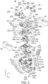
Fig. 3 is an exploded, perspective view showing the connector ofFig. 1 . -
Fig. 4 is another exploded, perspective view showing the connector ofFig. 1 . -
Fig. 5 is a perspective view showing one of terminals included in the connector ofFig. 1 . -
Fig. 6 is a perspective view showing an upper housing included in the connector ofFig. 1 . -
Fig. 7 is a perspective view showing one of locators included in the connector ofFig. 1 . -
Fig. 8 is another perspective view showing the locator ofFig. 7 . -
Fig. 9 is a perspective view showing a shell included in the connector ofFig. 1 . -
Fig. 10 is a perspective view showing a main portion of the connector ofFig. 1 . Each of the locators is positioned at a first position. -
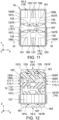
Fig. 11 is a top view showing the main portion ofFig. 9 . -
Fig. 12 is a longitudinal sectional view showing the main portion ofFig. 10 , taken along line XI-XI. -
Fig. 13 is another longitudinal sectional view showing the main portion ofFig. 10 . The cutting position is same as that inFig. 12 . Each of the locators is positioned at a second position. -
Fig. 14 is a perspective view showing the main portion of the connector ofFig. 1 and one of the cables. End portions of electric wires of the cable are inserted into receiving holes of a second locator, respectively. Each of the locators is positioned at the first position. -
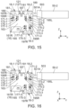
Fig. 15 is a side view showing the main portion and the cable ofFig. 14 . -
Fig. 16 is another side view showing the main portion and the cable ofFig. 14 . The second locator is positioned at the second position. -
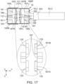
Fig. 17 is a top view showing the main portion and the cable ofFig. 14 . Receiving surfaces and therearound are illustrated in an enlarged fashion. -
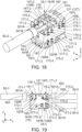
Fig. 18 is a perspective view showing the main portion and the cable ofFig. 16 . The second locator is removed. -
Fig. 19 is a perspective, side view showing an assembly of the main portion ofFig. 16 and the cables. Each of the locators is positioned at the second position. -
Fig. 20 is a perspective view showing the assembly ofFig. 19 and an upper cover. The upper cover is not attached to the shell. -
Fig. 21 is a perspective view showing the assembly and the upper cover ofFig. 20 . The upper cover is attached to the shell. -
Fig. 22 is a perspective view showing the assembly and the upper cover ofFig. 21 and fixing blocks. The upper cover is fixed to the fixing blocks with screws. -
Fig. 23 is a perspective view showing the assembly ofFig. 22 and a lower cover. The lower cover is not attached to the shell. -
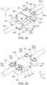
Fig. 24 is a perspective view showing the assembly and the lower cover ofFig. 23 . The lower cover is attached to the shell and fixed to the fixing block with screws. -
Fig. 25 is a perspective view showing an assembly of a connector according to a second embodiment of the present invention and cables. The connector connects two cables to each other. -
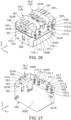
Fig. 26 is a perspective view showing a main portion of the connector ofFig. 25 . Each of locators is positioned at a first position. -
Fig. 27 is another perspective view showing the main portion ofFig. 26 . -
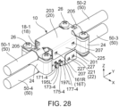
Fig. 28 is a perspective view showing an assembly of a connector according to a third embodiment of the present invention and cables. The connector connects four cables to one another. -
Fig. 29 is a perspective view showing a main portion of the connector ofFig. 28 . Each of locators is positioned at a first position. -
Fig. 30 is another perspective view showing the main portionFig. 29 . -
Fig. 31 is a figure showing an insulation displacement connection connector disclosed in Patent Document 1. - While the invention is susceptible to various modifications and alternative forms, specific embodiments thereof are shown by way of example in the drawings and will herein be described in detail. It should be understood, however, that the drawings and detailed description thereto are not intended to limit the invention to the particular form disclosed, but on the contrary, the intention is to cover all modifications, equivalents and alternatives falling within the spirit and scope of the present invention as defined by the appended claims.
- As shown in
Fig. 1 , aconnector 10 according to a first embodiment of the present invention is for connectingcables 50 to one another. In the present embodiment, theconnector 10 connects threecables 50 to one another. However, the present invention is not limited thereto. Theconnector 10 of the present invention may connect twocables 50 to each other or connect four ormore cables 50 to one another. - As shown in
Fig. 2 , in the present embodiment, each of thecables 50 is a twisted pair cable provided with twoelectric wires 501, i.e. 501A and 501B. Moreover, in the present embodiment, each of thecables 50 has a shieldingconductor 503. In other words, in the present embodiment, each of thecables 50 is a shielded twisted pair (STP) cable. In the present embodiment, the shieldingconductor 503 is folded back at an end portion thereof. However, the present invention is not limited thereto. Each of thecables 50 may be an unshielded twisted pair (UTP) cable. Each of thecables 50 should be provided with at least oneelectric wire 501, and theconnector 10 may be formed according to the number of the at least oneelectric wire 501. For example, the present invention is applicable to a connector for connecting coaxial cables to each other. - Referring to
Figs. 3 and4 , theconnector 10 is provided with ahousing 12, at least oneterminal 14, ashell 16 and at least onelocator 18. - As shown in
Figs. 3 and4 , in the present embodiment, thehousing 12 consists of two parts, i.e., anupper housing 121 and alower housing 123. In the present embodiment, an up-down direction is a Z-direction. However, the present invention is not limited thereto. Thehousing 12 may consist of a single part. - As shown in
Figs. 3 and4 , in the present embodiment, the at least oneterminal 14 is two in number. The number of theterminals 14 correspond to the number of theelectric wires 501 included in each of the cables 50 (seeFig. 2 ). In other words, in the present embodiment, theconnector 10 is provided with the twoterminals 14, i.e., afirst terminal 14A and asecond terminal 14B, which respectively correspond to the twoelectric wires 501, i.e. 501A and 501B, of each of thecables 50. The twoterminals 14 have shapes symmetrical to each other with respect to a plane perpendicular to a width direction and are arranged so that they are apart from each other in the width direction. In the present embodiment, the width direction is an X-direction. The twoterminals 14 have the shapes symmetrical to each other, so that they have signal transmission path lengths equal to each other and transmission characteristics same as each other. - As understood from
Fig. 3 , theshell 16 has twoshell sidewall portions 161, i.e. 161R and 161L, which are apart from each other in the width direction and twocoupling wall portions 163 which couple theshell sidewall portions 161 to each other. As shown inFig. 4 , theshell 16 further has abottom plate portion 165 covering a bottom of theshell 16 in part. In the present embodiment, theshell 16 is formed of a conductive metal sheet. However, the present invention is not limited thereto. Theshell 16 may be made of resin. Nevertheless, it is preferable that theshell 16 is made of conductive metal in consideration of strength thereof and an electromagnetic shield effect thereof. - As shown in
Figs. 3 and4 , in the present embodiment, the at least onelocator 18 is three in number. Thelocators 18 correspond to thecables 50, respectively. In other words, first, second and third locators 18-1, 18-2 and 18-3 correspond to first, second and third cables 50-1, 50-2 and 50-3, respectively. However, the present invention is not limited thereto. The number of thelocators 18 may be fewer than the number of thecables 50. For example, theconnector 10 may have onelocator 18 corresponding to any one of theelectric wires 501. Alternatively, onelocator 18 may correspond to two ormore cables 50. Nevertheless, that thelocators 18 correspond to thecables 50 in a one-to-one relationship provides better operability. - As shown in
Figs. 3 and4 , theconnector 10 further has an upper cover portion (a cover portion) 20, alower cover portion 22, two fixingblocks 24 and a plurality ofscrews 26. Theupper cover portion 20 is made of metal and provided with twocover sidewall portions 201, acoupling portion 203 and two attachingportions 205. Thecover sidewall portions 201 are arranged apart from each other in the width direction. Thecoupling portion 203 couples thecover sidewall portions 201 to each other. Thelower cover portion 22 is made of metal and provided with twocover sidewall portions 221 and acoupling portion 223. Thecover sidewall portions 221 are arranged apart from each other in the width direction. Thecoupling portion 223 couples thecover sidewall portions 221 to each other. In the present invention, thecover portion 20, the fixing blocks 24 and thescrews 26 are not essential. However, these hold the cables 50 (seeFig. 1 ) and cause an electromagnetic shield effect. - Referring to
Fig. 5 , theterminal 14A has afirst portion 141 having a plate-like shape, asecond portion 143 having a plate-like shape and acoupling portion 145 coupling thefirst portion 141 and thesecond portion 143 to each other. As mentioned above, thesecond terminal 14B has a shape symmetrical to that of the terminal 14A. - As shown in
Fig. 5 , thefirst portion 141 and thesecond portion 143 of the terminal 14A extend in a first direction perpendicular to the width direction. Thefirst portion 141 and thesecond portion 143 are arranged apart from each other in a second direction, which is perpendicular to the width direction and intersects with the first direction, and arranged in parallel to each other. Thecoupling portion 145 couples one end portion of thefirst portion 141 to a middle portion of thesecond portion 143. In the present embodiment, the first direction is the Z-direction which is identical with the up-down direction. However, in the present invention, the first direction may be inclined to the up-down direction. Moreover, in the present embodiment, the second direction is a Y-direction perpendicular to the first direction. Hereinafter, in this description, the Y-direction may be referred to as a front-rear direction. A negative Y-direction may be referred to as a forward direction while a positive Y-direction may be referred to as a rearward direction. - As shown in
Fig. 5 , the other end portion of thefirst portion 141 of thefirst terminal 14A and both end portions of thesecond portion 143 of the terminal 14A are respectively provided with the connection portions 147, i.e., first, second and third connection portions 147-1, 147-2 and 147-3. The first connection portion 147-1 and the second connection portion 147-2 are arranged so that their projections are identical to each other in the second direction. The second connection portion 147-2 and the third connection portion 147-3 have shapes symmetrical to each other in the first direction. - As understood from
Figs. 3 and4 , the connection portions 147 respectively correspond to thecables 50. Moreover, each of the connection portions 147 of thefirst terminal 14A respectively correspond to theelectric wire 501A which is one of theelectric wires 501 of thecable 50 corresponding thereto. Thus, the connection portions 147-1, 147-2 and 147-3 of thefirst terminal 14A are respectively connected to theelectric wires 501A of the cables 50-1, 50-2 and 50-3 which are different from one another. In the present embodiment, each of the connection portions 147 is an insulation displacement connection piece having a bifurcate shape and extending in the first direction. However, the present invention is not limited thereto. The shape of the terminal 14 and the shape of the connection portion 147 are not specifically limited. The number of the connection portions 147 of the terminal 14 depends on the number of thecables 50. The terminal 14 should have at least two connection portions 147. - Referring to
Fig. 6 , theupper housing 121 has abase portion 125, which has a flat plate-like shape, and amiddle wall 127, which protrudes upward from thebase portion 125. In the present embodiment, theupper housing 121 has a shape which is rotationally symmetrical about a central axis extending along the up-down direction. - As shown in
Fig. 6 , thebase portion 125 of theupper housing 121 is formed with a plurality of throughholes 131 piercing it in the up-down direction. In the present embodiment, the throughholes 131 are four in number. The throughholes 131 correspond to the connection portions 147 of theterminals 14, respectively. In detail, the throughholes 131 of theupper housing 121 respectively correspond to the first connection portion 147-1 of thefirst terminal 14A, the second connection portion 147-2 of thefirst terminal 14A, the first connection portion 147-1 of thesecond terminal 14B and the second connection portion 147-2 of thesecond terminal 14B. Each of the throughholes 131 has a size into which the connection portion 147 is insertable. - As shown in
Fig. 6 , thebase portion 125 is further formed with twoguide portions 133. Each of theguide portions 133 is a recess recessed downward from an upper surface of thebase portion 125. - As shown in
Fig. 6 , themiddle wall 127 of theupper housing 121 has at least one receivingsurface 135. In the present embodiment, theupper housing 121 has four receivingsurfaces 135. Each of the receiving surfaces 135 corresponds to any one of theelectric wires 501 of thecables 50. In the present embodiment, the receivingsurfaces 135 are bottom surfaces ofgrooves 137 formed in themiddle wall 127. Each of thegrooves 137 is depressed toward the middle of themiddle wall 127 in the front-rear direction and extends in the first direction. The bottom surfaces of thegrooves 137 intersect with the second direction. Two of the receivingsurfaces 135 are directed forward. The remaining two of the receivingsurfaces 135 are directed rearward. Moreover, the receivingsurfaces 135 correspond to the throughholes 131, respectively. Each of the receiving surfaces 135 is aligned with the throughhole 131 corresponding thereto in the front-rear direction. - As understood from
Figs. 3 and4 , thelower housing 123 has a shape which is generally identical to that of theupper housing 121 which is inverted. However, throughholes 131 formed in thelower housing 123 are two in number. The throughholes 131 respectively correspond to the third connection portion 147-3 of thefirst terminal 14A and the third connection portion 147-3 of the terminal 14B. However, the present invention is not limited thereto. Thelower housing 123 may be formed so that it is identical to theupper housing 121. - As understood from
Figs. 3 and4 , theupper housing 121 and thelower housing 123 partly sandwich theterminals 14 and hold them. Each of the connection portions 147 of theterminals 14 passes through the throughhole 131 corresponding thereto and is exposed outside. - Referring to
Figs. 7 and 8 , the first locator 18-1 has amain portion 181 and twosupport portions 183, i.e. 183R and 183L. In the present embodiment, the first locator 18-1 further has twoauxiliary portions 185, i.e. 185R and 185L. Thesupport portions 183 are located at both sides of themain portion 181 in the width direction and extend from themain portion 181 in the first direction. Each of thesupport portions 183 is resiliently deformable, so that a tip thereof is movable at least in the width direction. Theauxiliary portions support portions main portion 181 in the first direction. - Referring to
Figs. 3 and4 in addition toFigs. 7 and 8 , themain portion 181 of the first locator 18-1 is provided with afirst end face 187 and asecond end face 189. Thefirst end face 187 and thesecond end face 189 are located at both ends of the first locator 18-1 in the second direction. - As shown in
Figs. 7 and 8 , themain portion 181 of the first locator 18-1 is further formed with at least one receivinghole 191 and at least one admittingportion 193. In the present embodiment, the first locator 18-1 is formed with two receivingholes portions holes portions - As understood from
Figs. 7 and 8 , the receivingholes electric wires holes second end face 189 to thefirst end face 187, so that it can receive an end portion of theelectric wire holes electric wire - As understood from
Figs. 3 and4 , the admittingportions terminals portions first terminal 14A and the first connection portion 147-1 of thesecond terminal 14B, which are connected to theelectric wire portions portions hole - As shown in
Figs. 7 and 8 , the first locator 18-1 is further provided with twoprotrusions 195, i.e. 195R and 195L. Thesupport portions protrusions protrusions support portion protrusions shell sidewall portions shell 16 and protrude outward in the width direction. Theprotrusions support portions support portions - As shown in
Figs. 7 and 8 , the first locator 18-1 is further provided with twoauxiliary protrusions 197, i.e. 197R and 197L. Theauxiliary protrusions auxiliary portions auxiliary protrusions 197R and 197I protrude outward in the width direction. Theauxiliary protrusions protrusions 195 in the front-rear direction. Moreover, theauxiliary protrusions main portion 181 than theprotrusions - As shown in
Fig. 8 , the first locator 18-1 is further provided with a guidedportion 199 extending in the first direction. The guidedportion 199 protrudes downward from themain portion 181. The guidedportion 199 corresponds to one of theguide portions 133 of theupper housing 121. Theguide portion 133 receives the guidedportion 199 corresponding thereto and guides a movement of the guidedportion 199 or the first locator 18-1. - As understood from
Figs. 3 and4 , each of a second locator 18-2 and a third locator 18-3 is formed so that it is identical to the first locator 18-1. The admittingportions first terminal 14A and the second connection portion 147-2 of thesecond terminal 14B which are connected to theelectric wires portions first terminal 14A and the third connection portion 147-3 of thesecond terminal 14B which are connected to theelectric wires - Referring to
Fig. 9 , each of theshell sidewall portions shell 16 is provided with at least one set of afirst hole 171 and asecond hole 173, wherein the at least one set of thefirst hole 171 and thesecond hole 173 correspond to the at least onelocator 18. In the present embodiment, each of theshell sidewall portions first holes 171, i.e. 171-1, 171-2 and 171-3, and thesecond holes 173, i.e. 173-1, 173-2 and 173-3. The first hole 171-1 and the second hole 173-1 correspond to the first locator 18-1. The first hole 171-2 and the second hole 173-2 correspond to the second locator 18-2. The first hole 171-3 and the second hole 173-3 correspond to the third locator 18-3. - As shown in
Fig. 9 , each of theshell sidewall portions third hole 175 and afourth hole 177, wherein the at least one set of thethird hole 175 and thefourth hole 177 correspond to the at least onelocator 18. In the present embodiment, each of theshell sidewall portions third holes 175, i.e. 175-1, 175-2 and 175-3, and thefourth holes 177, i.e. 177-1, 177-2 and 177-3. The third hole 175-1 and the fourth hole 177-1 correspond to the first locator 18-1. The third hole 175-2 and the fourth hole 177-2 correspond to the second locator 18-2. The third hole 175-3 and the fourth hole 177-3 correspond to the third locator 18-3. - As understood from
Figs. 9 , in each of theshell sidewall portions first holes 171, i.e. 171-1, 171-2 and 171-3, and thesecond holes 173, i.e. 173-1, 173-2 and 173-3, pierces theshell sidewall portion first holes 171 and thesecond holes 173, thefirst hole 171 and thesecond hole 173 are located apart from each other in the first direction. Similarly, in each of theshell sidewall portions third holes 175, i.e. 175-1, 175-2 and 175-3, and thefourth holes 177, i.e. 177-1, 177-2 and 177-3, pierces theshell sidewall portion first holes 171 and thesecond holes 173, thethird hole 175 and thefourth hole 177 are located apart from each other in the first direction. In the present embodiment, in each of the sets of thefirst holes 171 and thesecond holes 173, thefirst hole 171 and thesecond hole 173 correspond to theprotrusions locator 18 corresponding thereto. Moreover, in the present embodiment, in each of the sets of thefirst holes 171 and thesecond holes 173, thethird hole 175 and thefourth hole 177 correspond to theauxiliary protrusions locator 18 corresponding thereto. - As understood from
Figs. 3 and10 , theshell 16 can accommodate thehousing 12, which holds theterminals 14, and thelocators 18 in the inside thereof. In a state that thehousing 12 is accommodated in theshell 16, the receivingsurfaces 135 of thehousing 12 and theshell sidewall portions accommodation portions 167 for accommodating thelocators 18. In the present embodiment, theconnector 10 is formed with three accommodation portions 167 (only one of which is shown), and theaccommodation portions 167 correspond to thelocators 18, respectively. - Referring to
Fig. 10 , each of thelocators 18 is attached to theshell 16 and partly accommodated in theaccommodation portion 167 corresponding thereto. In a state that thelocator 18 is attached to theshell 16, thefirst end face 187 of thelocator 18 is nearer to the receivingsurfaces 135 of thehousing 12 than thesecond end face 189 is in the second direction. In detail, thefirst end face 187 of the first locator 18-1 is directed rearward in the front-rear direction while thesecond end face 189 of the first locator 18-1 is directed forward in the front-rear direction. Thefirst end face 187 of each of the second locator 18-2 and the third locator 18-3 is directed forward in the front-rear direction while thesecond end face 189 of each of the second locator 18-2 and the third locator 18-3 is directed rearward in the front-rear direction. Hereinafter, the description for the first locator 18-1 is applicable to the second locator 18-2 and the third locator 18-3 with the necessary modification. Similarly, the description for the second locator 18-2 is applicable to the first locator 18-1 and the third locator 18-3 with the necessary modification. - As understood from
Fig. 11 , a size of themain portion 181 of the first locator 18-1 is slightly smaller than an internal size of theshell 16 in the width direction. In addition, a total size of thelocator 18 with theprotrusions 195, i.e. 195R and 195L, is larger than the internal size of theshell 16 in the width direction. - As understood from
Figs. 3 and10 , attachment of thelocator 18 to theshell 16 is carried out by pressing thelocator 18 toward theaccommodation portion 167 corresponding thereto along the first direction. As shown inFigs. 7 and 8 , a size of theprotrusion 195, i.e. 195R or 195L, is reduced toward a tip thereof. Because of the shape of theprotrusion 195, the attachment of thelocator 18 to theshell 16 can be easily carried out. Theprotrusions 195 can enter theaccommodation portions 167 mainly owing to resilient deformation of thesupport portions 183, and theauxiliary protrusions 197 can enter theaccommodation portions 167 mainly owing to resilient deformation of theshell 16. - As understood from
Fig. 10 , when each of theprotrusions accommodation portion 167, reaches thefirst hole 171 corresponding thereto, it enters thefirst hole 171 owing to reaction of thesupport portion 183. Moreover, when each of theauxiliary protrusions 197, i.e. 197R and 197L, which enters theaccommodation portion 167, reaches thethird hole 175 corresponding thereto, it enters thethird hole 175 owing to reaction of theshell 16. Thus, when thelocator 18 is attached to theshell 16, each of theprotrusions 195 is positioned in thefirst hole 171 corresponding thereto while each of theauxiliary protrusions 197 is positioned in thethird hole 175 corresponding thereto. In the following description, the position of thelocator 18 at this time with respect to theshell 16 is referred to as a first position. In other words, in the present embodiment, when thelocator 18 is positioned at the first position, each of theprotrusions 195 is positioned in thefirst hole 171 corresponding to thelocator 18 while each of theauxiliary protrusions 197 is positioned in thethird hole 175. - Referring to
Fig. 12 , when the first locator 18-1 is positioned at the first position, each of the receiving surfaces 135 is visible through each of the receivingholes 191, i.e. 191R and 191L, thereof. In detail, when the first locator 18-1 is positioned at the first position, a part of a region occupied by each of the receivingholes 191 is included in a region occupied by the receivingsurface 135 corresponding thereto in the first direction while a remaining part of the region occupied by the receivinghole 191 is out of the region occupied by the receivingsurface 135 in the first direction. At this time, the connection portion 147 (seeFig. 13 ) corresponding to each of the receivingholes 191 is not visible in the receivinghole 191. In this state, each of the receivingholes 191 allows the end portion of theelectric wire 501 corresponding thereto to be inserted therein and a tip of theelectric wire 501 to be brought into abutment with the receivingsurface 135. As just described, when thelocator 18 is positioned at the first position, the tip of theelectric wire 501 inserted into the receivinghole 191 can be brought into abutment with the receivingsurface 135. - Referring to
Figs. 14 and15 , the second locator 18-2 is positioned at the first position, and theelectric wires 501, i.e. 501R and 501L, are inserted into the receivingholes 191, i.e. 191R and 191L, of the second locator 18-2, respectively. Here, as shown inFig. 11 , when the second locator 18-2 is attached to theshell 16, a gap remains between thefirst end face 187 of the second locator 18-2 and each of the receivingsurfaces 135 of theupper housing 121 in the second direction. Accordingly, as shown inFig. 17 , the tips of theelectric wires 501 of the second cable 50-2 are visible when viewed along the first direction, wherein theelectric wires 501 are inserted in the receivingholes 191 of the second locator 18-2. Thus, it can be confirmed whether the tips of theelectric wires 501 of the second cable 50-2 are brought into abutment with the receivingsurfaces 135 or not, wherein theelectric wires 501 are inserted in the receivingholes 191 of the second locator 18-2. With this structure, connections of theelectric wires 501 to theconnector 10 can be securely carried out. - As described above with reference to
Figs. 7 and 8 , the size of theprotrusion 195 in the width direction is reduced toward the tip thereof. According to this shape of theprotrusion 195, when thelocator 18 receives a force directed into theaccommodation portion 167, theprotrusion 195 positioned in thefirst hole 171 can easily come out from thefirst hole 171. In contrast, when thelocator 18 receives a force directed outward of theaccommodation portion 167, coming out of theprotrusion 195 positioned in thefirst hole 171 from thefirst hole 171 is regulated. In other words, theprotrusions 195 prevent thelocator 18 attached to theshell 16 from falling away from theshell 16. Moreover, theauxiliary protrusion 197 is set in shape and in size so that it cannot come out from thethird hole 175 when thelocator 18 receives a relatively small force and so that it can come out from thethird hole 175 when thelocator 18 receives a relatively large force. It also depends on a shape and a position of theprotrusion 195 whether theauxiliary protrusion 197 can come out from thethird hole 175 or not. - As understood from a comparison between
Fig. 12 andFig. 13 or betweenFig. 15 and Fig. 16 , upon further pushing the second locator 18-2 positioned at the first position into theaccommodation portion 167, theprotrusions 195, i.e. 195R and 195L, come out from the first holes 171-2 and go towards the second holes 173-2, and theauxiliary protrusions 197, i.e. 197R and 197L, come out from the third holes 175-2 and go towards the fourth holes 177-2. Then, upon reaching the second holes 173-2, theprotrusions 195 enter the second holes 173-2. In addition, upon reaching the fourth holes 177-2, theauxiliary protrusions 197 enter the fourth holes 177-2. In this description, a position of thelocator 18 with respect to theshell 16 is referred to as a second position when theprotrusions 195 are positioned in thesecond holes 173 while theauxiliary protrusions 197 are positioned in thefourth holes 177. In other words, in the present embodiment, when thelocator 18 is positioned at the second position, each of theprotrusions 195 is positioned in thesecond hole 173 corresponding to thelocator 18 while each of theauxiliary protrusions 197 is positioned in thefourth hole 177. As mentioned above, thelocator 18 is attached to theshell 16 so that thelocator 18 is movable from the first position to the second position in the first direction. In addition, when each of theprotrusions 195 is positioned in thesecond hole 173 of theshell sidewall portion locator 18 from the second position to the first position is regulated by theprotrusions 195 and thesecond holes 173. - Referring to
Fig. 13 , when thelocator 18 is positioned at the second position, a range occupied by the receivinghole 191, i.e. 191R or 191L, overlaps with a range occupied by the receivingsurface 135 in the first direction. At this time, the connection portion 147 is partly visible in the receivinghole 191. This means that the connection portions 147 correspond to thelocator 18 are partly located in the receiving holes 191. With this structure, theelectric wires 501 can be connected to the connection portions 147 as shown inFig. 18 by inserting, into the receivingholes 191 of thelocator 18 positioned at the first position, the end portions of theelectric wires 501 corresponding thereto and then by moving thelocator 18 from the first position to the second position. - As shown in
Fig. 19 , when the cables 50-1, 50-2 and 50-3 are attached to theconnector 10, the locators 18-1, 18-2 and 18-3 are positioned at the second positions, respectively. - Referring to
Fig. 20 , thecoupling portion 203 of theupper cover portion 20 has an approximately rectangular shape and a size which allows thecoupling portion 203 to cover theshell 16 when viewed along the up-down direction. Thecover sidewall portions 201 have approximately rectangular shapes long in the front-rear direction and extend downward in the up-down direction from both edges of thecoupling portion 203. Each of thecover sidewall portions 201 hasspring pieces 207 protruding inward in the width direction. In the present embodiment, each of thecover sidewall portions 201 has twospring pieces 207. Thespring pieces 207 respectively correspond to the first holes 171-1 and 171-2, which correspond to the first locator 18-1 and the second locator 18-2, of theshell 16. The attachingportions 205 adjoin a front portion and a rear portion of thecoupling portion 203, respectively. Each of the attachingportions 205 is formed withscrew holes 209 piercing it in the up-down direction. - As understood from
Figs. 20 and 21 , theupper cover portion 20 is attached to theshell 16 in a state that the first locator 18-1 and the second locator 18-2 are positioned at the second positions. In a state that theupper cover portion 20 is attached to theshell 16, thecover sidewall portions 201 are positioned outward of theshell sidewall portions spring pieces 207 is positioned in thefirst hole 171 corresponding thereto when theupper cover portion 20 is attached to theshell 16. When at least one of the first locator 18-1 and the second locator 18-2 is positioned at the first position, any or all of thespring pieces 207 cannot enter thefirst holes 171 corresponding thereto. Accordingly, theupper cover portion 20 cannot be attached to theshell 16. - As shown in
Fig. 22 , theupper cover portion 20 is fixed to the fixing blocks 24 with thescrews 26. The cables 50-1 and 50-2 are sandwiched and fixed between the attachingportions 205 and the fixing blocks 24, respectively. Thus, theelectric wires 501 of the cables 50-1 and 50-2 are prevented from coming off from theconnector 10. Moreover, the shieldingconductors 503 of thecables 50 are electrically connected to theupper cover portion 20 so that an electromagnetic shield effect is improved. - Referring to
Fig. 23 , thelower cover portion 22 has the twocover sidewall portions 221, thecoupling portion 223 and an attachingportion 225. Thelower cover portion 22 is made of metal. When viewed along the up-down direction, thecoupling portion 223 has an approximately rectangular shape and a size which covers a half of theshell 16. Thecover sidewall portions 221 extend upward in the up-down direction from both edges of thecoupling portion 223. Each of thecover sidewall portions 221 hasspring pieces 227 protruding inward in the width direction. In the present embodiment, each of thecover sidewall portions 221 has twospring pieces 227. Thespring pieces 227 respectively correspond to the first hole 171-3 and the third hole 175-3, which correspond to the third locator 18-3, of theshell 16. The attachingportion 225 adjoins a rear portion of thecoupling portion 223. The attachingportion 225 is formed withscrew holes 229 piercing it in the up-down direction. - As understood from
Figs. 23 and24 , thelower cover portion 22 is attached to theshell 16 in a state that the third locator 18-3 is positioned at the second position. In a state that thelower cover portion 22 is attached to theshell 16, thecover sidewall portions 221 are positioned outward of theshell sidewall portions lower cover portion 22 is attached to theshell 16, thespring pieces 227 are respectively positioned in the first hole 171-3 and the third hole 175-3 which correspond to them. When the third locator 18-3 is positioned at the first position, thespring pieces 227 cannot enter the first hole 171-3 and the third hole 175-3 corresponding to them. Accordingly, thelower cover portion 22 cannot be attached to theshell 16. - As shown in
Fig. 24 , thelower cover portion 22 is fixed to one of the fixing blocks 24 with thescrews 26. The cable 50-3 is sandwiched between thelower cover portion 22 of the fixingblock 24. Thus, theelectric wires 501 of the cable 50-3 are prevented from coming off from theconnector 10. Moreover, the shieldingconductor 503 of the cable 50-3 is electrically connected to thelower cover portion 22, so that an electromagnetic shield effect is improved. - As described above, the use of the
connector 10 according to the present embodiment enables mutual connection of thecables 50 with simple operation. The gaps are provided between thefirst end face 187 of thelocator 18 and the receivingsurfaces 135 of thehousing 12 in the second direction, and the gaps are made visible from outside. Accordingly, connections of theelectric wires 501 of thecable 50 to theconnector 10 can be surely carried out. - The
connector 10 according to the present embodiment can be used as a branch connector which divides a transmission line, a signal transmission path or a power supply line into two. Here, a conventional branch connector takes a form of hanging a branch line from a main line. Accordingly, it is necessary to secure some length of the main line previously. Therefore, a problem that the main line is too long or too short may be caused. In contrast to this, a branch device having three connection portions, like that of the present invention, can extend the main line whenever a branch line is connected. In addition, the branch device allows a long main line to be cut and used. Even in that case, it is hard to cause a useless part of the main line. - Referring to
Fig. 25 , aconnector 10S according to a second embodiment of the present invention connects twocables 50, i.e. 50-1 and 50-2, to each other. - As understood from
Figs. 26 and 27 , theconnector 10S of the present embodiment is almost same as theconnector 10 of the first embodiment, except that the third locator 18-3 and its related components are removed. - As shown in
Figs. 26 and 27 , ashell 16S is smaller than theshell 16 in size in the first direction and has abottom plate portion 165S covering a bottom portion of theconnector 10S. In the present embodiment, each of terminals (not shown) is same as the terminal 14 (seeFig. 5 ), except that the third connection portion 147-3 is removed. - The
connector 10S according to the present embodiment can connect the twocables 50 to each other with easy operation. For example, theconnector 10S can be used as an extension connector for extending a transmission line, a signal transmission path or a power supply line. - Referring to
Fig. 28 , a connector 10T according to a third embodiment of the present invention connects fourcables 50, i.e. 50-1, 50-2, 50-3 and 50-4, to each other. - As understood from
Figs. 29 and30 , the connector 10T of the present embodiment is almost same as theconnector 10 according to the first embodiment, except that a fourth locator 18-4 is added. In the present embodiment, the fourth locator 18-4 is formed so that it is same as the first locator 18-1. - As understood from
Figs. 29 and30 , each ofshell sidewall portions shell 16T is formed with a first hole 171-4, a second hole 173-4, a third hole 175-4 and a fourth hole 177-4 which correspond to the fourth locator 18-4. In the present embodiment, each of terminals (not shown) is same as the terminal 14 (seeFig. 5 ), except that the terminal is provided with a fourth connection portion, which extends in a direction opposite to that of the first connection portion 147-1 and faces the third connection portion 147-3. The fourth connection portion and the third connection portion 147-3 are positioned so that their projections are identical with each other in the second direction. The fourth connection portion and the first connection portion 147-1 have shapes symmetrical to each other in the first direction. - The connector 10T according to the present embodiment can connect the four
cables 50 to each other with easy operation. In a manner similar to the case of the first embodiment, the connector 10T can be used as a branch connector which divides a transmission line, a signal transmission path or a power supply line into three. - Although the specific explanation about the present invention is made above with reference to the embodiments, the present invention is not limited thereto but susceptible of various modifications and alternative forms without departing from the spirit of the invention. For example, although all the
electric wires 501 are connected to the connection portions 147 corresponding to them by insulation displacement connection in each of the aforementioned embodiments, a part of theelectric wires 501 may be soldered to a terminal(s) or screwed to a terminal block. - Although the number of the
cables 50 is equal to the number of the connection portions 147 of the terminal 14 in each of the aforementioned embodiments, a connector of the present invention may be provided with a plurality of terminals each of which has connection portions 147 fewer in number than thecables 50. For example, a connector of the present invention may be a connector which is connected to four cables and provided with two sets of terminals each of which connects two cables to each other. - While there has been described what is believed to be the preferred embodiment of the invention, those skilled in the art will recognize that other and further modifications may be made thereto without departing from the spirit of the invention, and it is intended to claim all such embodiments that fall within the true scope of the invention.
Claims (12)
- A connector which connects cables to each other, wherein:the connector comprises a housing, at least one terminal, a shell and at least one locator;each of the cables comprises at least one electric wire;the terminal has at least two connection portions;the connection portions are respectively connected to the electric wires of the cables;the shell has two shell sidewall portions which are apart from each other in a width direction;each of shell sidewall portions is provided with at least one set of a first hole and a second hole corresponding to the locator;the first hole and the second hole of the one set pierce the shell sidewall portion in the width direction and are apart from each other in a first direction perpendicular to the width direction;the locator is attached to the shell so that the locator is movable from a first position to a second position in the first direction;the locator corresponds to at least one of the cables and to the connection portion connected to the electric wire of the cable corresponding thereto;the locator is provided with a first end face, a second end face, a receiving hole, an admitting portion and two protrusions;the first end face and the second end face are located at both ends of the locator in a second direction, which is perpendicular to the width direction and intersects with the first direction;the receiving hole pierces the locator from the second end face to the first end face and is receivable an end of the electric wire of the cable corresponding to the locator;the admitting portion communicates with the receiving hole and allows the connection portion corresponding to the locator to be moved when the locator is moved;the protrusions correspond to the shell sidewall portions, respectively;each of the protrusions protrudes outward in the width direction;when the locator is positioned at the first position, each of the protrusions is positioned in the first hole corresponding to the locator; andwhen the locator is positioned at the second position, each of the protrusions is positioned in the second hole corresponding to the locator, and the connection portion corresponding to the locator is in the receiving hole in part.
- The connector as recited in claim 1, wherein:the at least one locator comprises two or more locators; andthe locators correspond to the connection portions, respectively.
- The connector as recited in claim 1 or 2, wherein:the at least one locator comprises three or more locators;the at least two connection portions of the terminal comprises three or more connection portions; andthe locators correspond to the connection portions, respectively.
- The connector as recited in any one of claims 1 to 3 ; wherein:each of the cables is a twisted pair cable comprising two electric wires;the connector comprises two terminals as the at least one terminal;the terminals correspond to the two electric wires, respectively; andthe two terminals have shapes symmetrical to each other.
- The connector as recited in any one of claims 1 to 4, wherein each of the connection portions comprises an insulation displacement connection piece having a bifurcate shape and extending in the first direction.
- The connector as recited in any one of claims 1 to 5, wherein:the locator has a main portion and two support portions extending from the main portion in the first direction;the receiving hole is provided in the main portion;the support portions are resiliently deformable and correspond to the protrusions, respectively;each of the protrusions is supported by the support portion corresponding thereto and movable at least in the width direction; andwhen each of the protrusions is positioned in the second hole of the shell sidewall portion corresponding thereto, movement of the locator from the second position toward the first position is regulated.
- The connector as recited in any one of claims 1 to 6, wherein:the housing has at least one receiving surface intersecting with the second direction;the receiving surface of the housing and the shell sidewall portions form an accommodation portion which accommodates the locator;when the locator is positioned at the second position, a region occupied by the receiving hole included in a region occupied by the receiving surface in the first direction; andwhen the locator is positioned at the first position, a part of the region occupied by the receiving hole is included in the region occupied by the receiving surface in the first direction while a remaining part of the region occupied by the receiving hole is out of the region occupied by the receiving surface in the first direction.
- The connector as recited in any one of claims 1 to 7, wherein:the housing has at least one receiving surface intersecting with the second direction;the receiving surface of the housing and the shell sidewall portions form an accommodation portion which accommodates the locator;the first end face of the locator is nearer to the receiving surface of the housing than to the second end face of the locator in the second direction;when the locator is positioned at the first position, the end of the electric wire inserted in the receiving hole is possible to be brought into abutment with the receiving surface; anda gap remains between the first end face of the locator and the receiving surface of the housing in the second direction.
- The connector as recited in any one of claims 1 to 8, wherein:the locator is provided with a guided portion extending in the first direction; andthe housing is provided with a guide portion which receives and guides the guided portion.
- The connector as recited in any one of claims 1 to 9, wherein the shell is made of conductive metal.
- The connector as recited in any one of claim 1 to 10, wherein:the connector further has a cover portion;the cover portion is made of metal;the cover portion comprises two cover sidewall portions which are apart from each other in the width direction and a coupling portion which connects the cover sidewall portions to each other;each of the cover sidewall portions has a spring piece protruding inward in the width direction;in a state that the locator is positioned at the second position, the cover portion is attached to the shell; andin a state that the cover portion is attached to the shell, the cover sidewall portions are positioned outward of the shell sidewall portions while the spring piece is positioned in the first hole.
- The connector as recited in claim 11, wherein:the cable comprises a shielding conductor; andthe cover portion is connected to the shielding conductor.
Applications Claiming Priority (1)
| Application Number | Priority Date | Filing Date | Title |
|---|---|---|---|
| JP2023084506A JP2024168094A (en) | 2023-05-23 | 2023-05-23 | Connector |
Publications (2)
| Publication Number | Publication Date |
|---|---|
| EP4468522A1 true EP4468522A1 (en) | 2024-11-27 |
| EP4468522B1 EP4468522B1 (en) | 2026-06-17 |
Family
ID=90482533
Family Applications (1)
| Application Number | Title | Priority Date | Filing Date |
|---|---|---|---|
| EP24166541.3A Active EP4468522B1 (en) | 2023-05-23 | 2024-03-26 | Connector |
Country Status (4)
| Country | Link |
|---|---|
| US (1) | US20240396234A1 (en) |
| EP (1) | EP4468522B1 (en) |
| JP (1) | JP2024168094A (en) |
| CN (1) | CN119029616A (en) |
Citations (4)
| Publication number | Priority date | Publication date | Assignee | Title |
|---|---|---|---|---|
| JP2006236855A (en) | 2005-02-25 | 2006-09-07 | Matsushita Electric Works Ltd | Connector for pressure contact connection |
| CA2275923C (en) * | 1997-10-30 | 2006-12-19 | Thomas & Betts International, Inc. | Electrical connector having an improved connector shield and a multi-purpose strain relief |
| US8052461B2 (en) * | 2008-04-01 | 2011-11-08 | Fengliang WANG | Bayonet type electronic connector |
| JP2019021462A (en) * | 2017-07-14 | 2019-02-07 | 第一精工株式会社 | connector |
Family Cites Families (6)
| Publication number | Priority date | Publication date | Assignee | Title |
|---|---|---|---|---|
| US5364288A (en) * | 1992-07-24 | 1994-11-15 | North American Philips Corporation | Electrical connecting device |
| ATE306727T1 (en) * | 1999-01-15 | 2005-10-15 | Whitaker Corp | CONNECTOR FOR TERMINATING TELEVISION CABLES |
| US7156688B2 (en) * | 2002-05-31 | 2007-01-02 | Molex Incorporated | Insulation displacement connector |
| CN109478742B (en) * | 2016-07-20 | 2020-12-04 | 广濑电机株式会社 | Cable connector with cable holder |
| DE102021128871A1 (en) * | 2021-11-05 | 2023-05-11 | Erni International Ag | Connector, connector assembly, and a tool and method for assembling the connector assembly |
| US12469988B2 (en) * | 2022-10-21 | 2025-11-11 | Te Connectivity Solutions Gmbh | Direct connector for flat flexible cable |
-
2023
- 2023-05-23 JP JP2023084506A patent/JP2024168094A/en active Pending
-
2024
- 2024-03-25 US US18/614,948 patent/US20240396234A1/en active Pending
- 2024-03-26 EP EP24166541.3A patent/EP4468522B1/en active Active
- 2024-04-22 CN CN202410483290.3A patent/CN119029616A/en active Pending
Patent Citations (4)
| Publication number | Priority date | Publication date | Assignee | Title |
|---|---|---|---|---|
| CA2275923C (en) * | 1997-10-30 | 2006-12-19 | Thomas & Betts International, Inc. | Electrical connector having an improved connector shield and a multi-purpose strain relief |
| JP2006236855A (en) | 2005-02-25 | 2006-09-07 | Matsushita Electric Works Ltd | Connector for pressure contact connection |
| US8052461B2 (en) * | 2008-04-01 | 2011-11-08 | Fengliang WANG | Bayonet type electronic connector |
| JP2019021462A (en) * | 2017-07-14 | 2019-02-07 | 第一精工株式会社 | connector |
Also Published As
| Publication number | Publication date |
|---|---|
| CN119029616A (en) | 2024-11-26 |
| JP2024168094A (en) | 2024-12-05 |
| US20240396234A1 (en) | 2024-11-28 |
| EP4468522B1 (en) | 2026-06-17 |
Similar Documents
| Publication | Publication Date | Title |
|---|---|---|
| US5372513A (en) | Electrical connector with cable shield ground clip | |
| CN201126894Y (en) | Electrical Connector Assembly | |
| US10644414B2 (en) | Terminal fitting and connector | |
| CN116565595A (en) | Electric connector and electric connector combination | |
| US12327948B2 (en) | High density coupling panel | |
| CN103975488A (en) | cable plug connector | |
| GB2325793A (en) | Electrical connector | |
| KR20060050386A (en) | Connector and cable retainer | |
| KR20140085327A (en) | Cable connector and connector device having the same | |
| US20250233348A1 (en) | Couplers for single pair connectors | |
| US20200185855A1 (en) | Connector and connector assembly | |
| US20240396234A1 (en) | Connector | |
| WO2012142011A1 (en) | Connector | |
| JP3066799B2 (en) | connector | |
| JP2001043934A (en) | Photoelectric composite connector | |
| JP7522588B2 (en) | Locator, harness and method for manufacturing harness | |
| JP2023159884A (en) | Connector assemblies including connectors and connectors | |
| CN111864434B (en) | Electric connector and manufacturing method thereof | |
| CN103633507B (en) | Electric connector | |
| EP4300712A1 (en) | Connector | |
| CN223527557U (en) | Electric connector and connector assembly | |
| JPH1126103A (en) | connector | |
| JP7480821B2 (en) | Electrical Connectors | |
| US20260142421A1 (en) | Connector assembly with improved tongue plate for protecting conductive terminals | |
| US20250286293A1 (en) | Connector device and electric connector |
Legal Events
| Date | Code | Title | Description |
|---|---|---|---|
| PUAI | Public reference made under article 153(3) epc to a published international application that has entered the european phase |
Free format text: ORIGINAL CODE: 0009012 |
|
| STAA | Information on the status of an ep patent application or granted ep patent |
Free format text: STATUS: THE APPLICATION HAS BEEN PUBLISHED |
|
| AK | Designated contracting states |
Kind code of ref document: A1 Designated state(s): AL AT BE BG CH CY CZ DE DK EE ES FI FR GB GR HR HU IE IS IT LI LT LU LV MC ME MK MT NL NO PL PT RO RS SE SI SK SM TR |
|
| STAA | Information on the status of an ep patent application or granted ep patent |
Free format text: STATUS: REQUEST FOR EXAMINATION WAS MADE |
|
| 17P | Request for examination filed |
Effective date: 20250415 |
|
| GRAP | Despatch of communication of intention to grant a patent |
Free format text: ORIGINAL CODE: EPIDOSNIGR1 |
|
| STAA | Information on the status of an ep patent application or granted ep patent |
Free format text: STATUS: GRANT OF PATENT IS INTENDED |
|
| RIC1 | Information provided on ipc code assigned before grant |
Ipc: H01R 4/2433 20180101AFI20251221BHEP |
|
| INTG | Intention to grant announced |
Effective date: 20260119 |
|
| GRAS | Grant fee paid |
Free format text: ORIGINAL CODE: EPIDOSNIGR3 |
|
| GRAA | (expected) grant |
Free format text: ORIGINAL CODE: 0009210 |
|
| STAA | Information on the status of an ep patent application or granted ep patent |
Free format text: STATUS: THE PATENT HAS BEEN GRANTED |
|
| AK | Designated contracting states |
Kind code of ref document: B1 Designated state(s): AL AT BE BG CH CY CZ DE DK EE ES FI FR GB GR HR HU IE IS IT LI LT LU LV MC ME MK MT NL NO PL PT RO RS SE SI SK SM TR |
|
| REG | Reference to a national code |
Ref country code: CH Ref legal event code: F10 Free format text: ST27 STATUS EVENT CODE: U-0-0-F10-F00 (AS PROVIDED BY THE NATIONAL OFFICE) Effective date: 20260617 Ref country code: GB Ref legal event code: FG4D |
|
| REG | Reference to a national code |
Ref country code: DE Ref legal event code: R096 Ref document number: 602024005440 Country of ref document: DE |
|
| REG | Reference to a national code |
Ref country code: IE Ref legal event code: FG4D |