EP4468510A1 - Electrode assembly structure, and cylindrical battery, battery pack and vehicle comprising same - Google Patents
Electrode assembly structure, and cylindrical battery, battery pack and vehicle comprising same Download PDFInfo
- Publication number
- EP4468510A1 EP4468510A1 EP23843394.0A EP23843394A EP4468510A1 EP 4468510 A1 EP4468510 A1 EP 4468510A1 EP 23843394 A EP23843394 A EP 23843394A EP 4468510 A1 EP4468510 A1 EP 4468510A1
- Authority
- EP
- European Patent Office
- Prior art keywords
- electrode assembly
- electrode
- assembly structure
- uncoated portion
- structure according
- Prior art date
- Legal status (The legal status is an assumption and is not a legal conclusion. Google has not performed a legal analysis and makes no representation as to the accuracy of the status listed.)
- Pending
Links
Images







Classifications
-
- H—ELECTRICITY
- H01—ELECTRIC ELEMENTS
- H01M—PROCESSES OR MEANS, e.g. BATTERIES, FOR THE DIRECT CONVERSION OF CHEMICAL ENERGY INTO ELECTRICAL ENERGY
- H01M50/00—Constructional details or processes of manufacture of the non-active parts of electrochemical cells other than fuel cells, e.g. hybrid cells
- H01M50/20—Mountings; Secondary casings or frames; Racks, modules or packs; Suspension devices; Shock absorbers; Transport or carrying devices; Holders
- H01M50/204—Racks, modules or packs for multiple batteries or multiple cells
- H01M50/207—Racks, modules or packs for multiple batteries or multiple cells characterised by their shape
- H01M50/213—Racks, modules or packs for multiple batteries or multiple cells characterised by their shape adapted for cells having curved cross-section, e.g. round or elliptic
-
- H—ELECTRICITY
- H01—ELECTRIC ELEMENTS
- H01M—PROCESSES OR MEANS, e.g. BATTERIES, FOR THE DIRECT CONVERSION OF CHEMICAL ENERGY INTO ELECTRICAL ENERGY
- H01M50/00—Constructional details or processes of manufacture of the non-active parts of electrochemical cells other than fuel cells, e.g. hybrid cells
- H01M50/50—Current conducting connections for cells or batteries
- H01M50/572—Means for preventing undesired use or discharge
- H01M50/584—Means for preventing undesired use or discharge for preventing incorrect connections inside or outside the batteries
- H01M50/59—Means for preventing undesired use or discharge for preventing incorrect connections inside or outside the batteries characterised by the protection means
-
- H—ELECTRICITY
- H01—ELECTRIC ELEMENTS
- H01M—PROCESSES OR MEANS, e.g. BATTERIES, FOR THE DIRECT CONVERSION OF CHEMICAL ENERGY INTO ELECTRICAL ENERGY
- H01M10/00—Secondary cells; Manufacture thereof
- H01M10/04—Construction or manufacture in general
- H01M10/0431—Cells with wound or folded electrodes
-
- H—ELECTRICITY
- H01—ELECTRIC ELEMENTS
- H01M—PROCESSES OR MEANS, e.g. BATTERIES, FOR THE DIRECT CONVERSION OF CHEMICAL ENERGY INTO ELECTRICAL ENERGY
- H01M10/00—Secondary cells; Manufacture thereof
- H01M10/04—Construction or manufacture in general
- H01M10/0404—Machines for assembling batteries
- H01M10/0409—Machines for assembling batteries for cells with wound electrodes
-
- H—ELECTRICITY
- H01—ELECTRIC ELEMENTS
- H01M—PROCESSES OR MEANS, e.g. BATTERIES, FOR THE DIRECT CONVERSION OF CHEMICAL ENERGY INTO ELECTRICAL ENERGY
- H01M10/00—Secondary cells; Manufacture thereof
- H01M10/04—Construction or manufacture in general
- H01M10/0422—Cells or battery with cylindrical casing
-
- H—ELECTRICITY
- H01—ELECTRIC ELEMENTS
- H01M—PROCESSES OR MEANS, e.g. BATTERIES, FOR THE DIRECT CONVERSION OF CHEMICAL ENERGY INTO ELECTRICAL ENERGY
- H01M10/00—Secondary cells; Manufacture thereof
- H01M10/60—Heating or cooling; Temperature control
- H01M10/65—Means for temperature control structurally associated with the cells
- H01M10/653—Means for temperature control structurally associated with the cells characterised by electrically insulating or thermally conductive materials
-
- H—ELECTRICITY
- H01—ELECTRIC ELEMENTS
- H01M—PROCESSES OR MEANS, e.g. BATTERIES, FOR THE DIRECT CONVERSION OF CHEMICAL ENERGY INTO ELECTRICAL ENERGY
- H01M50/00—Constructional details or processes of manufacture of the non-active parts of electrochemical cells other than fuel cells, e.g. hybrid cells
- H01M50/20—Mountings; Secondary casings or frames; Racks, modules or packs; Suspension devices; Shock absorbers; Transport or carrying devices; Holders
- H01M50/249—Mountings; Secondary casings or frames; Racks, modules or packs; Suspension devices; Shock absorbers; Transport or carrying devices; Holders specially adapted for aircraft or vehicles, e.g. cars or trains
-
- H—ELECTRICITY
- H01—ELECTRIC ELEMENTS
- H01M—PROCESSES OR MEANS, e.g. BATTERIES, FOR THE DIRECT CONVERSION OF CHEMICAL ENERGY INTO ELECTRICAL ENERGY
- H01M50/00—Constructional details or processes of manufacture of the non-active parts of electrochemical cells other than fuel cells, e.g. hybrid cells
- H01M50/20—Mountings; Secondary casings or frames; Racks, modules or packs; Suspension devices; Shock absorbers; Transport or carrying devices; Holders
- H01M50/289—Mountings; Secondary casings or frames; Racks, modules or packs; Suspension devices; Shock absorbers; Transport or carrying devices; Holders characterised by spacing elements or positioning means within frames, racks or packs
- H01M50/293—Mountings; Secondary casings or frames; Racks, modules or packs; Suspension devices; Shock absorbers; Transport or carrying devices; Holders characterised by spacing elements or positioning means within frames, racks or packs characterised by the material
-
- H—ELECTRICITY
- H01—ELECTRIC ELEMENTS
- H01M—PROCESSES OR MEANS, e.g. BATTERIES, FOR THE DIRECT CONVERSION OF CHEMICAL ENERGY INTO ELECTRICAL ENERGY
- H01M50/00—Constructional details or processes of manufacture of the non-active parts of electrochemical cells other than fuel cells, e.g. hybrid cells
- H01M50/40—Separators; Membranes; Diaphragms; Spacing elements inside cells
- H01M50/489—Separators, membranes, diaphragms or spacing elements inside the cells, characterised by their physical properties, e.g. swelling degree, hydrophilicity or shut down properties
-
- H—ELECTRICITY
- H01—ELECTRIC ELEMENTS
- H01M—PROCESSES OR MEANS, e.g. BATTERIES, FOR THE DIRECT CONVERSION OF CHEMICAL ENERGY INTO ELECTRICAL ENERGY
- H01M50/00—Constructional details or processes of manufacture of the non-active parts of electrochemical cells other than fuel cells, e.g. hybrid cells
- H01M50/50—Current conducting connections for cells or batteries
- H01M50/531—Electrode connections inside a battery casing
- H01M50/533—Electrode connections inside a battery casing characterised by the shape of the leads or tabs
-
- H—ELECTRICITY
- H01—ELECTRIC ELEMENTS
- H01M—PROCESSES OR MEANS, e.g. BATTERIES, FOR THE DIRECT CONVERSION OF CHEMICAL ENERGY INTO ELECTRICAL ENERGY
- H01M50/00—Constructional details or processes of manufacture of the non-active parts of electrochemical cells other than fuel cells, e.g. hybrid cells
- H01M50/50—Current conducting connections for cells or batteries
- H01M50/531—Electrode connections inside a battery casing
- H01M50/538—Connection of several leads or tabs of wound or folded electrode stacks
-
- H—ELECTRICITY
- H01—ELECTRIC ELEMENTS
- H01M—PROCESSES OR MEANS, e.g. BATTERIES, FOR THE DIRECT CONVERSION OF CHEMICAL ENERGY INTO ELECTRICAL ENERGY
- H01M50/00—Constructional details or processes of manufacture of the non-active parts of electrochemical cells other than fuel cells, e.g. hybrid cells
- H01M50/50—Current conducting connections for cells or batteries
- H01M50/543—Terminals
- H01M50/547—Terminals characterised by the disposition of the terminals on the cells
- H01M50/548—Terminals characterised by the disposition of the terminals on the cells on opposite sides of the cell
-
- H—ELECTRICITY
- H01—ELECTRIC ELEMENTS
- H01M—PROCESSES OR MEANS, e.g. BATTERIES, FOR THE DIRECT CONVERSION OF CHEMICAL ENERGY INTO ELECTRICAL ENERGY
- H01M50/00—Constructional details or processes of manufacture of the non-active parts of electrochemical cells other than fuel cells, e.g. hybrid cells
- H01M50/50—Current conducting connections for cells or batteries
- H01M50/543—Terminals
- H01M50/552—Terminals characterised by their shape
- H01M50/559—Terminals adapted for cells having curved cross-section, e.g. round, elliptic or button cells
-
- H—ELECTRICITY
- H01—ELECTRIC ELEMENTS
- H01M—PROCESSES OR MEANS, e.g. BATTERIES, FOR THE DIRECT CONVERSION OF CHEMICAL ENERGY INTO ELECTRICAL ENERGY
- H01M50/00—Constructional details or processes of manufacture of the non-active parts of electrochemical cells other than fuel cells, e.g. hybrid cells
- H01M50/50—Current conducting connections for cells or batteries
- H01M50/572—Means for preventing undesired use or discharge
- H01M50/584—Means for preventing undesired use or discharge for preventing incorrect connections inside or outside the batteries
-
- H—ELECTRICITY
- H01—ELECTRIC ELEMENTS
- H01M—PROCESSES OR MEANS, e.g. BATTERIES, FOR THE DIRECT CONVERSION OF CHEMICAL ENERGY INTO ELECTRICAL ENERGY
- H01M50/00—Constructional details or processes of manufacture of the non-active parts of electrochemical cells other than fuel cells, e.g. hybrid cells
- H01M50/50—Current conducting connections for cells or batteries
- H01M50/572—Means for preventing undesired use or discharge
- H01M50/584—Means for preventing undesired use or discharge for preventing incorrect connections inside or outside the batteries
- H01M50/59—Means for preventing undesired use or discharge for preventing incorrect connections inside or outside the batteries characterised by the protection means
- H01M50/593—Spacers; Insulating plates
-
- H—ELECTRICITY
- H01—ELECTRIC ELEMENTS
- H01M—PROCESSES OR MEANS, e.g. BATTERIES, FOR THE DIRECT CONVERSION OF CHEMICAL ENERGY INTO ELECTRICAL ENERGY
- H01M2200/00—Safety devices for primary or secondary batteries
-
- H—ELECTRICITY
- H01—ELECTRIC ELEMENTS
- H01M—PROCESSES OR MEANS, e.g. BATTERIES, FOR THE DIRECT CONVERSION OF CHEMICAL ENERGY INTO ELECTRICAL ENERGY
- H01M2220/00—Batteries for particular applications
- H01M2220/20—Batteries in motive systems, e.g. vehicle, ship, plane
-
- H—ELECTRICITY
- H01—ELECTRIC ELEMENTS
- H01M—PROCESSES OR MEANS, e.g. BATTERIES, FOR THE DIRECT CONVERSION OF CHEMICAL ENERGY INTO ELECTRICAL ENERGY
- H01M50/00—Constructional details or processes of manufacture of the non-active parts of electrochemical cells other than fuel cells, e.g. hybrid cells
- H01M50/30—Arrangements for facilitating escape of gases
- H01M50/383—Flame arresting or ignition-preventing means
-
- H—ELECTRICITY
- H01—ELECTRIC ELEMENTS
- H01M—PROCESSES OR MEANS, e.g. BATTERIES, FOR THE DIRECT CONVERSION OF CHEMICAL ENERGY INTO ELECTRICAL ENERGY
- H01M50/00—Constructional details or processes of manufacture of the non-active parts of electrochemical cells other than fuel cells, e.g. hybrid cells
- H01M50/40—Separators; Membranes; Diaphragms; Spacing elements inside cells
- H01M50/463—Separators, membranes or diaphragms characterised by their shape
- H01M50/469—Separators, membranes or diaphragms characterised by their shape tubular or cylindrical
-
- H—ELECTRICITY
- H01—ELECTRIC ELEMENTS
- H01M—PROCESSES OR MEANS, e.g. BATTERIES, FOR THE DIRECT CONVERSION OF CHEMICAL ENERGY INTO ELECTRICAL ENERGY
- H01M50/00—Constructional details or processes of manufacture of the non-active parts of electrochemical cells other than fuel cells, e.g. hybrid cells
- H01M50/60—Arrangements or processes for filling or topping-up with liquids; Arrangements or processes for draining liquids from casings
- H01M50/609—Arrangements or processes for filling with liquid, e.g. electrolytes
-
- Y—GENERAL TAGGING OF NEW TECHNOLOGICAL DEVELOPMENTS; GENERAL TAGGING OF CROSS-SECTIONAL TECHNOLOGIES SPANNING OVER SEVERAL SECTIONS OF THE IPC; TECHNICAL SUBJECTS COVERED BY FORMER USPC CROSS-REFERENCE ART COLLECTIONS [XRACs] AND DIGESTS
- Y02—TECHNOLOGIES OR APPLICATIONS FOR MITIGATION OR ADAPTATION AGAINST CLIMATE CHANGE
- Y02E—REDUCTION OF GREENHOUSE GAS [GHG] EMISSIONS, RELATED TO ENERGY GENERATION, TRANSMISSION OR DISTRIBUTION
- Y02E60/00—Enabling technologies; Technologies with a potential or indirect contribution to GHG emissions mitigation
- Y02E60/10—Energy storage using batteries
-
- Y—GENERAL TAGGING OF NEW TECHNOLOGICAL DEVELOPMENTS; GENERAL TAGGING OF CROSS-SECTIONAL TECHNOLOGIES SPANNING OVER SEVERAL SECTIONS OF THE IPC; TECHNICAL SUBJECTS COVERED BY FORMER USPC CROSS-REFERENCE ART COLLECTIONS [XRACs] AND DIGESTS
- Y02—TECHNOLOGIES OR APPLICATIONS FOR MITIGATION OR ADAPTATION AGAINST CLIMATE CHANGE
- Y02P—CLIMATE CHANGE MITIGATION TECHNOLOGIES IN THE PRODUCTION OR PROCESSING OF GOODS
- Y02P70/00—Climate change mitigation technologies in the production process for final industrial or consumer products
- Y02P70/50—Manufacturing or production processes characterised by the final manufactured product
Definitions
- the present disclosure relates to an electrode assembly structure, and a cylindrical battery, a battery pack, and a vehicle including the same. More specifically, the present disclosure relates to an electrode assembly structure that facilitates impregnation of electrolyte and discharge of gas, and reduces the risk of fire due to short circuit, and a cylindrical battery and a battery pack including the same.
- an electrode assembly in which a positive electrode tab and a negative electrode tab extend up and down along the height direction of the battery can, respectively, may be applied.
- a current collector may be used as an intermediate medium to connect the positive electrode tab and the negative electrode tab to the cell terminal and the battery can, respectively.
- the positive electrode current collector may be combined with the positive electrode tab while covering one side of the electrode assembly, and the negative electrode current collector may be combined with the negative electrode tab while covering the other side of the electrode assembly. Additionally, the positive electrode current collector may be electrically connected to the cell terminal, and the negative electrode current collector may be electrically connected to the battery can.
- the present disclosure is designed to solve the problems of the related art, and therefore the present disclosure is directed to facilitating impregnation of electrolyte and discharge of gas, and reducing the risk of fire due to short circuit.
- An electrode assembly structure may comprise a first electrode assembly wound around a winding axis, and a second electrode assembly wound around the winding axis, adjacent to the first electrode assembly, and located outer than the first electrode assembly in a radial direction, which is defined as a direction away from the winding axis, wherein in each of the first electrode assembly and the second electrode assembly, a stack including a first electrode having a first uncoated portion not coated with an active material layer along a winding direction, a second electrode having a second uncoated portion not coated with an active material layer along the winding direction, and a separator interposed therebetween may be wound around the common winding axis to form a core and an outer circumference.
- At least a part of the uncoated portion of the first electrode assembly and at least a part of the uncoated portion of the second electrode assembly may include a plurality of segments divided along the winding direction.
- the first electrode assembly may have no segment in an area corresponding to the part where the core is formed when wound.
- the second electrode assembly may have no segment in an area corresponding to the part where the outer circumference is formed when wound.
- the second electrode assembly may be located further outward in the radial direction than the first electrode assembly.
- the uncoated portion of the first electrode assembly and the uncoated portion of the second electrode assembly may be bent in the radial direction or in a direction opposite to the radial direction.
- the uncoated portion of the first electrode assembly and the uncoated portion of the second electrode assembly may be bent in opposite directions.
- the uncoated portion of the first electrode assembly is bent in a direction opposite to the radial direction.
- the uncoated portion of the second electrode assembly may be bent in the radial direction.
- the electrode assembly structure may further comprise a separating member located between the first electrode assembly and the second electrode assembly.
- the separating member may be configured to have an empty space formed between the outer circumference of the first electrode assembly and the inner circumference of the second electrode assembly.
- the separating member may have a discontinuous shape along a circumferential direction of the outer circumference of the first electrode assembly.
- the separating member may contain a material with electrical insulating properties.
- the separating member may contain a thermal conductive material.
- a cylindrical battery according to an embodiment of the present disclosure may comprise the electrode assembly structure according to the present disclosure; a battery housing having an opening formed on one side to accommodate the electrode assembly structure through the opening and electrically connected to the first electrode; a top cap configured to cover the opening; a terminal configured to protrude out of the battery housing through a closed portion located opposite to the opening and electrically connected to the second electrode; and a first current collector located on one side of the electrode assembly structure and configured to electrically connect the electrode assembly structure and the battery housing.
- the first current collector may include a first tab coupling portion coupled to the first uncoated portion of each of the first electrode assembly and the second electrode assembly; and a housing coupling portion coupled to the battery housing.
- a battery pack according to the present disclosure may comprise the cylindrical battery according to the present disclosure.
- a vehicle according to the present disclosure may comprise the battery pack according to the present disclosure.
- the electrode assembly structure is composed of a plurality of electrode assemblies, short-circuit current may be reduced, compared to the case where one electrode assembly is provided. This is because the short-circuit current is not generated by a short circuit that can occur in an electrode assembly configured entirely as one assembly, but generated by a short circuit that can occur in each of a plurality of electrode assemblies. Therefore, the risk of fire due to short circuit can be reduced.
- the electrode assembly structure may facilitate electrolyte impregnation and gas discharge. This is because the movement of electrolyte and gas can be facilitated through the space formed between the first electrode assembly and the second electrode assembly. In particular, the movement of the electrode assembly structure in the height direction can be smooth through the space provided in a direction parallel to the winding axis.
- the electrode assembly structure can be easily produced.
- the form factor increases, there is a high possibility of production defects, such as misalignment, as the stack containing electrodes and separators is wound several times to form one electrode assembly.
- the possibility of production defects can be reduced because the number of windings is reduced.
- bending of the uncoated portion is facilitated by forming a segment.
- the current collector on the surface formed by overlapping bent segments into several folds rather than separate tabs, it is easy to combine the electrode assembly structure and the current collector, and the area through which the current can move is expanded, thereby reducing resistance.
- the separating member may prevent clearance from occurring in the space between the first electrode assembly and the second electrode assembly.
- the separating member may be configured to have an empty space formed between the outer circumference of the first electrode assembly and the inner circumference of the second electrode assembly to facilitate the movement of electrolyte and gas.
- FIG. 1 is a drawing showing an electrode assembly structure 10 according to the present disclosure.
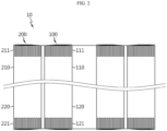
- FIG. 2 is a drawing showing a cross section of the electrode assembly structure 10 according to the present disclosure.
- FIG. 3 is a drawing showing a stack S according to the present disclosure.
- the electrode assembly structure 10 may include a first electrode assembly 100 and a second electrode assembly 200.
- the first electrode assembly 100 and the second electrode assembly 200 may be wound around a common winding axis.
- the first electrode assembly 100 and the second electrode assembly 200 may be adj acent to each other.
- the second electrode assembly 200 is adjacent to the first electrode assembly 100 and may be located outer than the first electrode assembly 100 in a radial direction, which is defined as a direction away from the winding axis.
- the first electrode assembly 100 may be located closer to the winding axis than the second electrode assembly 200.
- the second electrode assembly 200 may be located further outward than the first electrode assembly 100 in a radial direction.
- first electrode assembly 100 and the second electrode assembly 200 There may be a clearance between the first electrode assembly 100 and the second electrode assembly 200. However, the first electrode assembly 100 and the second electrode assembly 200 may be attached without any clearance.
- the outer diameter of the first electrode assembly 100 and the inner diameter of the second electrode assembly 200 may be approximately the same.
- the outer circumference of the first electrode assembly 100 and the inner circumference of the second electrode assembly 200 may face each other.
- first electrode assembly 100 and the second electrode assembly 200 represent electrode assemblies, which are included in the electrode assembly structure 10 and adjacent to each other, and the electrode assembly structure 10 is not limited to including only the first electrode assembly 100 and the second electrode assembly 200. That is, electrode assembly structure 10 may include two or more electrode assemblies.
- the stack S which includes the first electrode 110 having a first uncoated portion 111 not coated with an active material layer along the winding direction, the second electrode 120 having a second uncoated portion 121 not coated with an active material layer along the winding direction, and a separator M interposed between them, may be wound around a common winding axis to form a core and an outer circumference.
- the stack S which includes the first electrode 210 having a first uncoated portion 211 not coated with an active material layer along the winding direction, the second electrode 220 having a second uncoated portion 221 not coated with an active material layer along the winding direction, and a separator M interposed between them, may be wound around a common winding axis to form a core and an outer circumference.
- the short-circuit current may be reduced compared to the case where the electrode assembly structure is entirely configured with a single electrode assembly. This is because the short-circuit current is not generated by a short circuit that can occur in an electrode assembly configured entirely as one assembly, but generated by a short circuit that can occur in each of a plurality of electrode assemblies. Therefore, the risk of fire due to short circuit can be reduced.
- the electrode assembly structure 10 may facilitate electrolyte impregnation and gas discharge. This is because the movement of electrolyte and gas can be facilitated through the space formed between the first electrode assembly 100 and the second electrode assembly 200. In particular, the movement of the electrode assembly structure 10 in the height direction can be smooth through the space provided in a direction parallel to the winding axis.
- the electrode assembly structure 10 can be easily produced.
- the form factor increases, there is a high possibility of production defects, such as misalignment, as the stack containing electrodes and separators is wound several times to form one electrode assembly.
- the possibility of production defects can be reduced because the number of windings is reduced.
- FIG. 4 is a drawing showing a structure of electrodes 110, 120 of a first electrode assembly 100 included in the electrode assembly structure 10 according to the present disclosure.
- FIG. 5 is a drawing showing a structure of electrodes 210, 220 of a second electrode assembly 200 included in the electrode assembly structure 10 according to the present disclosure.
- At least a part of the uncoated portion 111, 121 of the first electrode assembly may include a plurality of segments A divided along the winding direction.
- At least a part of the uncoated portion 211, 221 of the second electrode assembly may include a plurality of segments A divided along the winding direction.
- the segment A may be processed by notching.
- the segment A may be trapezoidal in shape.
- the segment A may be transformed into a square, parallelogram, semicircle, or semi-elliptic shape.
- the height of the segment A of the uncoated portion 111, 121 of the first electrode assembly may gradually increase from the core to the outer circumference along the winding direction.
- the uncoated portion 111, 121 of the first electrode assembly may not form a segment A in the area corresponding to the portion where the core is formed when wound.
- the height of the segment A of the uncoated portion 211, 221 of the second electrode assembly may gradually decrease from the core to the outer circumference side along the winding direction.
- the uncoated portion 211, 221 of the second electrode assembly may not form a segment A in the area corresponding to the portion where the outer circumference is formed when wound.
- the segment A may be bent in the radial direction or in a direction opposite to the radial direction.
- the segment A may be overlapped into several layers by the bending.
- the first current collector 20 and/or the second current collector 60 which will be described later, may be coupled in an area where the plurality of segments A overlap in multiple layers.
- bending of the uncoated portion is easy by forming the segment A.
- coupling the current collector on the surface formed by overlapping several layers of the bent segments A rather than a separate tab it is easy to combine the electrode assembly structure 10 and the current collector, and the area through which the current can move is expanded, thereby reducing resistance.
- FIG. 6 is a diagram showing the process of coupling the electrode assembly structure 10 according to the present disclosure.
- FIG. 7 is a drawing showing the first electrode assembly 100 included in the electrode assembly structure 10 according to the present disclosure.
- FIG. 8 is a drawing showing the second electrode assembly 200 included in the electrode assembly structure 10 according to the present disclosure.
- the uncoated portion 111, 121 of the first electrode assembly may be bent in the radial direction or in a direction opposite to the radial direction.
- the uncoated portion 211, 221 of the second electrode assembly may be bent in the radial direction or in a direction opposite to the radial direction.
- the uncoated portion 111, 121 of the first electrode assembly and the uncoated portion 211, 221 of the second electrode assembly may be bent in opposite directions.
- the uncoated portion 111, 121 of the first electrode assembly may be bent in a direction opposite to the radial direction
- the uncoated portion 211, 221 of the second electrode assembly may be bent in the radial direction.
- the hole formed in the core of the first electrode assembly 100 is not closed by the bent uncoated portion 111, 121.
- the uncoated portion 211, 221 bent to the outer circumference of the second electrode assembly 200 do not protrude.
- the space formed between the first electrode assembly 100 and the second electrode assembly 200 is also not closed by the bent uncoated portions 111, 121, 211, 221. This is because the uncoated portion 111, 121 of the first electrode assembly is bent in a direction opposite to the radial direction, and the uncoated portion 211, 221 of the second electrode assembly is bent in the radial direction.
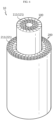
- FIG. 9 is a drawing showing the electrode assembly structure 10 according to the present disclosure.
- FIG. 10 is a diagram showing the process of coupling separating members 300 included in the electrode assembly structure 10 according to the present disclosure.
- the electrode assembly structure 10 may include a separating member 300.
- the separating member 300 may be located between the first electrode assembly 100 and the second electrode assembly 200.
- the separating member 300 may be configured to have an empty space formed between the outer circumference of the first electrode assembly 100 and the inner circumference of the second electrode assembly 200.
- the separating member 300 may have a discontinuous shape along the circumferential direction of the outer circumference of the first electrode assembly 100.
- the separating member 300 may include four members provided at radial intervals of 90 degrees on the outer circumference of the first electrode assembly 100. Each of the four members has a constant width along the outer circumference of the first electrode assembly 100 and a thickness corresponding to the gap between the outer circumference of the first electrode assembly 100 and the inner circumference of the second electrode assembly 200, and may have an extended form along in the height direction of the electrode assembly structure 10.
- the separating member 300 may contain a material having electrical insulation properties.
- the separating member 300 may contain a thermal conductive material.
- the separating member 300 may be configured to have an empty space formed between the outer circumference of the first electrode assembly 100 and the inner circumference of the second electrode assembly 200 to facilitate the movement of electrolyte and gas.
- the separating member 300 may contain a thermal conductive material, so if heat or fire occurs in the electrode assembly structure 10, the heat may be discharged through the separating member.
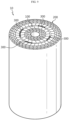
- FIG. 11 is a drawing showing a cylindrical battery 5 according to the present disclosure.
- the cylindrical battery 5 may include a battery housing 30, a top cap 40, a terminal 50, and a first current collector 20.
- the battery housing 30 may accommodate the electrode assembly structure 10 through an opening formed on one side.
- the battery housing 30 is a roughly cylindrical receptor with an opening formed on one side, and may be made of a conductive metal material.
- the battery housing 30 may be electrically connected to the first electrode 110, 210.
- the battery housing 30 can be used as an external terminal.
- the battery housing 30 may also accommodate electrolyte through the opening.
- the battery housing 30 in the present disclosure is not limited to this form.
- Top cap 40 may be configured to cover the opening.
- the top cap 40 may be configured to have no polarity.
- the top cap 40 may be made of metal to ensure rigidity, but even in this case, it may not have polarity.
- the top cap 40 may contain an insulating material.
- the present disclosure does not limit the top cap 40 as not having polarity, and the top cap 40 may have the same polarity as the battery housing 30.
- the top cap 40 may be provided with a venting portion 41.
- the venting portion 41 may be configured to be weak compared to the surrounding area. If the pressure inside the battery increases, the venting portion 41 may rupture to release gas.
- the venting portion 41 may be formed by partially reducing the thickness of the top cap 40 by notching on one or both sides of the top cap 40.
- the terminal 50 may protrude out of the battery housing 30 through a closed portion located opposite to the opening.
- the terminal 50 may be electrically connected to the second electrode 120, 220.
- the terminal 50 may penetrate approximately the center of the lower surface of the battery housing 30.
- the terminal 50 may be electrically connected to the electrode assembly structure 10 by combining with the second current collector 60, which will be described later.
- the first current collector 20 may be located on one side of the electrode assembly structure 10.
- the first current collector 20 may be electrically connected to the first electrode 110, 210.
- the first current collector 20 may electrically connect the electrode assembly structure 10 and the battery housing 30.
- the first current collector 20 may include a first tab coupling portion 21 and a housing coupling portion 22.
- the first tab coupling portion 21 may be coupled to the uncoated portion 111 of the first electrode assembly and the uncoated portion 211 of the second electrode assembly.
- the first tab coupling portion 21 may be located on the separating member 300.
- the first tab coupling portion 21 may extend from a support portion located on one side of the first electrode assembly 100 to one side of the second electrode assembly 200 and may be positioned on the separating member 300.
- the housing coupling portion 22 may be coupled to the battery housing 30.
- the housing coupling portion 22 may be coupled to the inner surface of the battery housing 30.
- the first tab coupling portion 21 of the first current collector is located on the separating member 300, when the first tab coupling portion 21 is coupled to the uncoated portion 111 of the first electrode assembly and the uncoated portion 211 of the second electrode assembly, the first tab coupling portion 21 may be stably supported by the separating member 300.
- the cylindrical battery 5 may include a second current collector 60 and/or an insulator 80 and/or a first gasket G1 and/or a second gasket G2.
- the second current collector 60 may be electrically coupled to the second electrode 120, 220.
- the second current collector 60 may be electrically coupled to the terminal 50.
- the second current collector 60 may include a terminal coupling portion 61 coupled to the terminal 50 and a second tab coupling portion 62 coupled to the second electrode 120, 220.
- the insulator 80 may be located between the electrode assembly structure 10 and the battery housing 30 to insulate the battery housing 30 and the second electrode 120, 220.
- the insulator 80 may be interposed between the closed portion of the battery housing 30 and the second current collector 60.
- the insulator 80 may include, for example, a resin material with insulating properties.
- the insulator 80 may have a hole approximately in the center so that the terminal 50 may be electrically connected to the second current collector 60.
- the first gasket G1 may be provided between the top cap 40 and the battery housing 30.
- the first gasket G1 prevents the top cap 40 and the battery housing 30 from contacting each other.
- the second gasket G2 may be provided between the terminal 50 and the battery housing 30.
- the second gasket G2 prevents the terminal 50 and the battery housing 30 from contacting each other.
- the first gasket G1 and the second gasket G2 may be made of a resin material with insulating properties and elasticity.
- FIG. 12 is a diagram showing a battery pack 3 according to the present disclosure.
- the battery pack 3 may include the cylindrical battery 5.
- the battery pack 3 may further include various components of the battery pack other than the cylindrical battery 5, such as BMS, busbar, pack case, relay, current sensor, etc. known at the time of filing the present disclosure.
- FIG. 13 is a drawing showing a vehicle 1 according to the present disclosure.
- the vehicle 1 according to the present disclosure may include the battery pack 3.
- the vehicle 1 may be a hybrid vehicle or an electric vehicle.
- the vehicle 1 according to the present disclosure further includes various other components included in the vehicle in addition to the battery pack 3.
- the vehicle 1 according to the present disclosure may further include a vehicle body, a motor, and control devices such as an ECU (electronic control unit) in addition to the battery pack 3 according to the present disclosure.
- ECU electronic control unit
Landscapes
- Chemical & Material Sciences (AREA)
- Chemical Kinetics & Catalysis (AREA)
- Electrochemistry (AREA)
- General Chemical & Material Sciences (AREA)
- Engineering & Computer Science (AREA)
- Manufacturing & Machinery (AREA)
- Aviation & Aerospace Engineering (AREA)
- Secondary Cells (AREA)
- Connection Of Batteries Or Terminals (AREA)
- Battery Mounting, Suspending (AREA)
- Cell Separators (AREA)
- Sealing Battery Cases Or Jackets (AREA)
Abstract
Description
- The present disclosure relates to an electrode assembly structure, and a cylindrical battery, a battery pack, and a vehicle including the same. More specifically, the present disclosure relates to an electrode assembly structure that facilitates impregnation of electrolyte and discharge of gas, and reduces the risk of fire due to short circuit, and a cylindrical battery and a battery pack including the same.
- The present application claims priority to
Korean Patent Application No. 10-2022-0089220 filed on July 19, 2022 - In a cylindrical battery, in order to maximize current collection efficiency, an electrode assembly in which a positive electrode tab and a negative electrode tab extend up and down along the height direction of the battery can, respectively, may be applied. In a cylindrical battery to which an electrode assembly having this structure is applied, a current collector may be used as an intermediate medium to connect the positive electrode tab and the negative electrode tab to the cell terminal and the battery can, respectively.
- In this case, for example, the positive electrode current collector may be combined with the positive electrode tab while covering one side of the electrode assembly, and the negative electrode current collector may be combined with the negative electrode tab while covering the other side of the electrode assembly. Additionally, the positive electrode current collector may be electrically connected to the cell terminal, and the negative electrode current collector may be electrically connected to the battery can.
- However, according to the conventional cylindrical battery having this structure, current is concentrated on the strip-shaped electrode tab connected to the positive electrode uncoated portion and/or the negative electrode uncoated portion, so resistance is high, a lot of heat is generated, and current collection efficiency is not good.
- For small cylindrical batteries with form factors of 1865 or 2170, resistance and heat generation are not a major issue. However, when the form factor is increased to apply the cylindrical battery to an electric vehicle, a problem may occur where the cylindrical battery ignites as a lot of heat is generated around the electrode tab during the rapid charging process. In addition, as the form factor increases, the diameter of the electrode assembly increases, resulting in a problem of inferior impregnability as the electrolyte cannot move to the center or outermost area of the electrode assembly when electrolyte is injected, compared to the existing cylindrical battery with a small form factor.
- In addition, when cylindrical batteries with an increased form factor are exposed to a high temperature environment for a long time, the separator shrinks, causing a short circuit between electrodes, and the increased form factor also increases the risk of fire.
- In the cylindrical battery having the structure described above, it became necessary to develop a cylindrical battery with a new structure that could solve the above problems.
- The present disclosure is designed to solve the problems of the related art, and therefore the present disclosure is directed to facilitating impregnation of electrolyte and discharge of gas, and reducing the risk of fire due to short circuit.
- However, the technical problem to be solved by the present disclosure is not limited to the above-mentioned problem, and other problems not mentioned will be clearly understood by those skilled in the art from the present disclosure described below.
- An electrode assembly structure according to an embodiment of the present disclosure may comprise a first electrode assembly wound around a winding axis, and a second electrode assembly wound around the winding axis, adjacent to the first electrode assembly, and located outer than the first electrode assembly in a radial direction, which is defined as a direction away from the winding axis,
wherein in each of the first electrode assembly and the second electrode assembly, a stack including a first electrode having a first uncoated portion not coated with an active material layer along a winding direction, a second electrode having a second uncoated portion not coated with an active material layer along the winding direction, and a separator interposed therebetween may be wound around the common winding axis to form a core and an outer circumference. - At least a part of the uncoated portion of the first electrode assembly and at least a part of the uncoated portion of the second electrode assembly may include a plurality of segments divided along the winding direction.
- The first electrode assembly may have no segment in an area corresponding to the part where the core is formed when wound.
- The second electrode assembly may have no segment in an area corresponding to the part where the outer circumference is formed when wound.
- The second electrode assembly may be located further outward in the radial direction than the first electrode assembly.
- The uncoated portion of the first electrode assembly and the uncoated portion of the second electrode assembly may be bent in the radial direction or in a direction opposite to the radial direction.
- The uncoated portion of the first electrode assembly and the uncoated portion of the second electrode assembly may be bent in opposite directions.
- The uncoated portion of the first electrode assembly is bent in a direction opposite to the radial direction.
- The uncoated portion of the second electrode assembly may be bent in the radial direction.
- The electrode assembly structure may further comprise a separating member located between the first electrode assembly and the second electrode assembly.
- The separating member may be configured to have an empty space formed between the outer circumference of the first electrode assembly and the inner circumference of the second electrode assembly.
- The separating member may have a discontinuous shape along a circumferential direction of the outer circumference of the first electrode assembly.
- The separating member may contain a material with electrical insulating properties.
- The separating member may contain a thermal conductive material.
- A cylindrical battery according to an embodiment of the present disclosure may comprise the electrode assembly structure according to the present disclosure; a battery housing having an opening formed on one side to accommodate the electrode assembly structure through the opening and electrically connected to the first electrode; a top cap configured to cover the opening; a terminal configured to protrude out of the battery housing through a closed portion located opposite to the opening and electrically connected to the second electrode; and a first current collector located on one side of the electrode assembly structure and configured to electrically connect the electrode assembly structure and the battery housing.
- The first current collector may include a first tab coupling portion coupled to the first uncoated portion of each of the first electrode assembly and the second electrode assembly; and a housing coupling portion coupled to the battery housing.
- A battery pack according to the present disclosure may comprise the cylindrical battery according to the present disclosure.
- A vehicle according to the present disclosure may comprise the battery pack according to the present disclosure.
- According to one aspect of the present disclosure, if the electrode assembly is exposed to high temperature for a long time and the separator shrinks to cause a short circuit between electrodes, since the electrode assembly structure is composed of a plurality of electrode assemblies, short-circuit current may be reduced, compared to the case where one electrode assembly is provided. This is because the short-circuit current is not generated by a short circuit that can occur in an electrode assembly configured entirely as one assembly, but generated by a short circuit that can occur in each of a plurality of electrode assemblies. Therefore, the risk of fire due to short circuit can be reduced.
- The electrode assembly structure may facilitate electrolyte impregnation and gas discharge. This is because the movement of electrolyte and gas can be facilitated through the space formed between the first electrode assembly and the second electrode assembly. In particular, the movement of the electrode assembly structure in the height direction can be smooth through the space provided in a direction parallel to the winding axis.
- The electrode assembly structure can be easily produced. In particular, when the form factor increases, there is a high possibility of production defects, such as misalignment, as the stack containing electrodes and separators is wound several times to form one electrode assembly. However, when producing and combining a plurality of smaller electrode assemblies, the possibility of production defects can be reduced because the number of windings is reduced.
- According to another aspect of the present disclosure, bending of the uncoated portion is facilitated by forming a segment. In addition, by combining the current collector on the surface formed by overlapping bent segments into several folds rather than separate tabs, it is easy to combine the electrode assembly structure and the current collector, and the area through which the current can move is expanded, thereby reducing resistance.
- According to still another aspect of the present disclosure, even if electrolyte or gas moves into the space formed between the first electrode assembly and the second electrode assembly, it does not affect the uncoated portion, and thus may reduce the possibility of a short circuit between the electrodes due to tearing of the uncoated portion or the separator.
- According to still another aspect of the present disclosure, the separating member may prevent clearance from occurring in the space between the first electrode assembly and the second electrode assembly. In addition to preventing clearance, the separating member may be configured to have an empty space formed between the outer circumference of the first electrode assembly and the inner circumference of the second electrode assembly to facilitate the movement of electrolyte and gas.
-
-
FIG. 1 is a drawing showing an electrode assembly structure according to the present disclosure. -
FIG. 2 is a drawing showing a cross section of the electrode assembly structure according to the present disclosure. -
FIG. 3 is a drawing showing a stack according to the present disclosure. -
FIG. 4 is a drawing showing an electrode structure of a first electrode assembly included in the electrode assembly structure according to the present disclosure. -
FIG. 5 is a drawing showing an electrode structure of a second electrode assembly included in the electrode assembly structure according to the present disclosure. -
FIG. 6 is a diagram showing the process of coupling the electrode assembly structure according to the present disclosure. -
FIG. 7 is a drawing showing the first electrode assembly included in the electrode assembly structure according to the present disclosure. -
FIG. 8 is a drawing showing the second electrode assembly included in the electrode assembly structure according to the present disclosure. -
FIG. 9 is a drawing showing the electrode assembly structure according to the present disclosure. -
FIG. 10 is a diagram showing the process of coupling separating members included in the electrode assembly structure according to the present disclosure. -
FIG. 11 is a drawing showing a cylindrical battery according to the present disclosure. -
FIG. 12 is a drawing showing a battery pack according to the present disclosure. -
FIG. 13 is a drawing showing a vehicle according to the present disclosure. - Hereinafter, preferred embodiments of the present disclosure will be described in detail with reference to the accompanying drawings. The accompanying drawings illustrate a preferred embodiment of the present disclosure and together with the foregoing disclosure, serve to provide further understanding of the technical features of the present disclosure, and thus, the present disclosure is not construed as being limited to the drawings. Like reference numerals refer to like elements. Additionally, in the drawings, the thickness, proportions and dimensions of components are exaggerated for effective explanation of technical content.
- It should be understood that the terms used in the specification and the appended claims should not be construed as limited to general and dictionary meanings, but interpreted based on the meanings and concepts corresponding to technical aspects of the present disclosure on the basis of the principle that the inventor is allowed to define terms appropriately for the best explanation.
- In this specification, terms indicating directions such as up, down, left, right, front, and back are used, but it is obvious to those skilled in the art of the present disclosure that these terms are only for convenience of explanation and they may vary depending on the location of the target object or the location of the observer.
- Accordingly, the embodiments described in this specification and the configurations shown in the drawings are only one of the most preferred embodiments of the present disclosure and do not represent all technical details of the present disclosure, so it should be understood that there may be various equivalents and variations that can be replaced at the time of filing this application.
-
FIG. 1 is a drawing showing anelectrode assembly structure 10 according to the present disclosure.FIG. 2 is a drawing showing a cross section of theelectrode assembly structure 10 according to the present disclosure.FIG. 3 is a drawing showing a stack S according to the present disclosure. - Referring to
FIGS. 1 to 3 , theelectrode assembly structure 10 according to the present disclosure may include afirst electrode assembly 100 and asecond electrode assembly 200. - The
first electrode assembly 100 and thesecond electrode assembly 200 may be wound around a common winding axis. Thefirst electrode assembly 100 and thesecond electrode assembly 200 may be adj acent to each other. Thesecond electrode assembly 200 is adjacent to thefirst electrode assembly 100 and may be located outer than thefirst electrode assembly 100 in a radial direction, which is defined as a direction away from the winding axis. - The
first electrode assembly 100 may be located closer to the winding axis than thesecond electrode assembly 200. Thesecond electrode assembly 200 may be located further outward than thefirst electrode assembly 100 in a radial direction. - There may be a clearance between the
first electrode assembly 100 and thesecond electrode assembly 200. However, thefirst electrode assembly 100 and thesecond electrode assembly 200 may be attached without any clearance. - The outer diameter of the
first electrode assembly 100 and the inner diameter of thesecond electrode assembly 200 may be approximately the same. The outer circumference of thefirst electrode assembly 100 and the inner circumference of thesecond electrode assembly 200 may face each other. - However, the
first electrode assembly 100 and thesecond electrode assembly 200 represent electrode assemblies, which are included in theelectrode assembly structure 10 and adjacent to each other, and theelectrode assembly structure 10 is not limited to including only thefirst electrode assembly 100 and thesecond electrode assembly 200. That is,electrode assembly structure 10 may include two or more electrode assemblies. - In the
first electrode assembly 100, the stack S, which includes thefirst electrode 110 having a firstuncoated portion 111 not coated with an active material layer along the winding direction, thesecond electrode 120 having a seconduncoated portion 121 not coated with an active material layer along the winding direction, and a separator M interposed between them, may be wound around a common winding axis to form a core and an outer circumference. - In the
second electrode assembly 200, the stack S, which includes thefirst electrode 210 having a firstuncoated portion 211 not coated with an active material layer along the winding direction, thesecond electrode 220 having a seconduncoated portion 221 not coated with an active material layer along the winding direction, and a separator M interposed between them, may be wound around a common winding axis to form a core and an outer circumference. - According to this configuration of the present disclosure, for example, in the case where the electrode assembly is exposed to high temperature for a long time so that the separator shrinks and a short circuit occurs between the electrodes, since the
electrode assembly structure 10 includes a plurality ofelectrode assemblies - The
electrode assembly structure 10 may facilitate electrolyte impregnation and gas discharge. This is because the movement of electrolyte and gas can be facilitated through the space formed between thefirst electrode assembly 100 and thesecond electrode assembly 200. In particular, the movement of theelectrode assembly structure 10 in the height direction can be smooth through the space provided in a direction parallel to the winding axis. - The
electrode assembly structure 10 can be easily produced. In particular, when the form factor increases, there is a high possibility of production defects, such as misalignment, as the stack containing electrodes and separators is wound several times to form one electrode assembly. However, when producing and combining a plurality of smaller electrode assemblies, the possibility of production defects can be reduced because the number of windings is reduced. -
FIG. 4 is a drawing showing a structure ofelectrodes first electrode assembly 100 included in theelectrode assembly structure 10 according to the present disclosure.FIG. 5 is a drawing showing a structure ofelectrodes second electrode assembly 200 included in theelectrode assembly structure 10 according to the present disclosure. - Referring again to
FIGS. 4 and5 , at least a part of theuncoated portion uncoated portion - The segment A may be processed by notching. The segment A may be trapezoidal in shape. However, the segment A may be transformed into a square, parallelogram, semicircle, or semi-elliptic shape.
- The height of the segment A of the
uncoated portion uncoated portion - The height of the segment A of the
uncoated portion uncoated portion - The segment A may be bent in the radial direction or in a direction opposite to the radial direction. The segment A may be overlapped into several layers by the bending. The first
current collector 20 and/or the secondcurrent collector 60, which will be described later, may be coupled in an area where the plurality of segments A overlap in multiple layers. - According to this structure of the present disclosure, bending of the uncoated portion is easy by forming the segment A. In addition, by coupling the current collector on the surface formed by overlapping several layers of the bent segments A rather than a separate tab, it is easy to combine the
electrode assembly structure 10 and the current collector, and the area through which the current can move is expanded, thereby reducing resistance. -
FIG. 6 is a diagram showing the process of coupling theelectrode assembly structure 10 according to the present disclosure.FIG. 7 is a drawing showing thefirst electrode assembly 100 included in theelectrode assembly structure 10 according to the present disclosure.FIG. 8 is a drawing showing thesecond electrode assembly 200 included in theelectrode assembly structure 10 according to the present disclosure. - Referring to
FIGS. 6 to 8 , theuncoated portion uncoated portion - The
uncoated portion uncoated portion FIGS. 6 to 8 , theuncoated portion uncoated portion - According to this structure in the present disclosure, the hole formed in the core of the
first electrode assembly 100 is not closed by the bentuncoated portion uncoated portion second electrode assembly 200 do not protrude. Additionally, the space formed between thefirst electrode assembly 100 and thesecond electrode assembly 200 is also not closed by the bentuncoated portions uncoated portion uncoated portion first electrode assembly 100 and thesecond electrode assembly 200, it does not affect the uncoated portion, thereby reducing the possibility of a short circuit between the electrodes due to tearing of the uncoated portion or the separator. -
FIG. 9 is a drawing showing theelectrode assembly structure 10 according to the present disclosure.FIG. 10 is a diagram showing the process ofcoupling separating members 300 included in theelectrode assembly structure 10 according to the present disclosure. - Referring to
FIGS. 9 and10 , theelectrode assembly structure 10 may include a separatingmember 300. - The separating
member 300 may be located between thefirst electrode assembly 100 and thesecond electrode assembly 200. The separatingmember 300 may be configured to have an empty space formed between the outer circumference of thefirst electrode assembly 100 and the inner circumference of thesecond electrode assembly 200. The separatingmember 300 may have a discontinuous shape along the circumferential direction of the outer circumference of thefirst electrode assembly 100. For example, the separatingmember 300 may include four members provided at radial intervals of 90 degrees on the outer circumference of thefirst electrode assembly 100. Each of the four members has a constant width along the outer circumference of thefirst electrode assembly 100 and a thickness corresponding to the gap between the outer circumference of thefirst electrode assembly 100 and the inner circumference of thesecond electrode assembly 200, and may have an extended form along in the height direction of theelectrode assembly structure 10. - The separating
member 300 may contain a material having electrical insulation properties. The separatingmember 300 may contain a thermal conductive material. - According to this structure of the present disclosure, it is possible to prevent clearance from occurring in the space between the
first electrode assembly 100 and thesecond electrode assembly 200 through the separatingmember 300. In addition to preventing clearance, the separatingmember 300 may be configured to have an empty space formed between the outer circumference of thefirst electrode assembly 100 and the inner circumference of thesecond electrode assembly 200 to facilitate the movement of electrolyte and gas. - The separating
member 300 may contain a thermal conductive material, so if heat or fire occurs in theelectrode assembly structure 10, the heat may be discharged through the separating member. -
FIG. 11 is a drawing showing acylindrical battery 5 according to the present disclosure. - Referring to
FIG. 11 , thecylindrical battery 5 according to the present disclosure may include abattery housing 30, atop cap 40, a terminal 50, and a firstcurrent collector 20. - The
battery housing 30 may accommodate theelectrode assembly structure 10 through an opening formed on one side. Thebattery housing 30 is a roughly cylindrical receptor with an opening formed on one side, and may be made of a conductive metal material. Thebattery housing 30 may be electrically connected to thefirst electrode battery housing 30 can be used as an external terminal. Thebattery housing 30 may also accommodate electrolyte through the opening. However, thebattery housing 30 in the present disclosure is not limited to this form. -
Top cap 40 may be configured to cover the opening. Thetop cap 40 may be configured to have no polarity. Thetop cap 40 may be made of metal to ensure rigidity, but even in this case, it may not have polarity. Thetop cap 40 may contain an insulating material. However, the present disclosure does not limit thetop cap 40 as not having polarity, and thetop cap 40 may have the same polarity as thebattery housing 30. - The
top cap 40 may be provided with a ventingportion 41. The ventingportion 41 may be configured to be weak compared to the surrounding area. If the pressure inside the battery increases, the ventingportion 41 may rupture to release gas. The ventingportion 41 may be formed by partially reducing the thickness of thetop cap 40 by notching on one or both sides of thetop cap 40. - The terminal 50 may protrude out of the
battery housing 30 through a closed portion located opposite to the opening. The terminal 50 may be electrically connected to thesecond electrode battery housing 30. The terminal 50 may be electrically connected to theelectrode assembly structure 10 by combining with the secondcurrent collector 60, which will be described later. - The first
current collector 20 may be located on one side of theelectrode assembly structure 10. The firstcurrent collector 20 may be electrically connected to thefirst electrode current collector 20 may electrically connect theelectrode assembly structure 10 and thebattery housing 30. - The first
current collector 20 may include a firsttab coupling portion 21 and ahousing coupling portion 22. The firsttab coupling portion 21 may be coupled to theuncoated portion 111 of the first electrode assembly and theuncoated portion 211 of the second electrode assembly. The firsttab coupling portion 21 may be located on the separatingmember 300. For example, the firsttab coupling portion 21 may extend from a support portion located on one side of thefirst electrode assembly 100 to one side of thesecond electrode assembly 200 and may be positioned on the separatingmember 300. Thehousing coupling portion 22 may be coupled to thebattery housing 30. Thehousing coupling portion 22 may be coupled to the inner surface of thebattery housing 30. - According to this structure in the present disclosure, since the first
tab coupling portion 21 of the first current collector is located on the separatingmember 300, when the firsttab coupling portion 21 is coupled to theuncoated portion 111 of the first electrode assembly and theuncoated portion 211 of the second electrode assembly, the firsttab coupling portion 21 may be stably supported by the separatingmember 300. - Referring back to
FIG. 11 , thecylindrical battery 5 according to the present disclosure may include a secondcurrent collector 60 and/or aninsulator 80 and/or a first gasket G1 and/or a second gasket G2. - The second
current collector 60 may be electrically coupled to thesecond electrode current collector 60 may be electrically coupled to the terminal 50. The secondcurrent collector 60 may include aterminal coupling portion 61 coupled to the terminal 50 and a secondtab coupling portion 62 coupled to thesecond electrode - The
insulator 80 may be located between theelectrode assembly structure 10 and thebattery housing 30 to insulate thebattery housing 30 and thesecond electrode insulator 80 may be interposed between the closed portion of thebattery housing 30 and the secondcurrent collector 60. Theinsulator 80 may include, for example, a resin material with insulating properties. Theinsulator 80 may have a hole approximately in the center so that the terminal 50 may be electrically connected to the secondcurrent collector 60. - The first gasket G1 may be provided between the
top cap 40 and thebattery housing 30. The first gasket G1 prevents thetop cap 40 and thebattery housing 30 from contacting each other. - The second gasket G2 may be provided between the terminal 50 and the
battery housing 30. The second gasket G2 prevents the terminal 50 and thebattery housing 30 from contacting each other. - The first gasket G1 and the second gasket G2 may be made of a resin material with insulating properties and elasticity.
-
FIG. 12 is a diagram showing abattery pack 3 according to the present disclosure. - Referring to
FIG. 12 , thebattery pack 3 according to the present disclosure may include thecylindrical battery 5. Thebattery pack 3 may further include various components of the battery pack other than thecylindrical battery 5, such as BMS, busbar, pack case, relay, current sensor, etc. known at the time of filing the present disclosure. -
FIG. 13 is a drawing showing avehicle 1 according to the present disclosure. - Referring to
FIG. 13 , thevehicle 1 according to the present disclosure may include thebattery pack 3. Thevehicle 1 may be a hybrid vehicle or an electric vehicle. Thevehicle 1 according to the present disclosure further includes various other components included in the vehicle in addition to thebattery pack 3. For example, thevehicle 1 according to the present disclosure may further include a vehicle body, a motor, and control devices such as an ECU (electronic control unit) in addition to thebattery pack 3 according to the present disclosure. - As described above, the present disclosure has been described with a focus on preferred embodiments with reference to the accompanying drawings, but it is clear to those skilled in the art that many various obvious modifications can be made from this description without departing from the scope of the present disclosure. Accordingly, the scope of the present disclosure should be construed in terms of the appended claims to include such many modified examples.
-
- 1 vehicle
- 3 battery pack
- 5 cylindrical battery
- 10 electrode assembly structure
- 100 first electrode assembly
- 110 first electrode
- 111 first uncoated portion
- 120 second electrode
- 121 second uncoated portion
- 200 second electrode assembly
- 210 first electrode
- 211 first uncoated portion
- 220 second electrode
- 221 second uncoated portion
- 300 separating member
- 20 first current collector
- 21 first tab coupling portion
- 22 housing coupling portion
- 30 battery housing
- 40 top cap
- 41 venting portion
- 50 terminal
- 60 second current collector
- 61 tab coupling portion
- 62 terminal coupling portion
- 80 insulator
- G1 first gasket
- G2 second gasket
- M separator
- A segment
Claims (15)
- An electrode assembly structure, comprising a first electrode assembly wound around a winding axis, and a second electrode assembly wound around the winding axis, adjacent to the first electrode assembly, and located outer than the first electrode assembly in a radial direction, which is defined as a direction away from the winding axis,
wherein in each of the first electrode assembly and the second electrode assembly, a stack including a first electrode having a first uncoated portion not coated with an active material layer along a winding direction, a second electrode having a second uncoated portion not coated with an active material layer along the winding direction, and a separator interposed therebetween is wound around the common winding axis to form a core and an outer circumference. - The electrode assembly structure according to claim 1, wherein at least a part of the uncoated portion of the first electrode assembly and at least a part of the uncoated portion of the second electrode assembly include a plurality of segments divided along the winding direction.
- The electrode assembly structure according to claim 2, wherein the first electrode assembly has no segment in an area corresponding to the part where the core is formed when wound, and
wherein the second electrode assembly has no segment in an area corresponding to the part where the outer circumference is formed when wound. - The electrode assembly structure according to claim 1, wherein the uncoated portion of the first electrode assembly and the uncoated portion of the second electrode assembly are bent in the radial direction or in a direction opposite to the radial direction.
- The electrode assembly structure according to claim 1, wherein the uncoated portion of the first electrode assembly and the uncoated portion of the second electrode assembly are bent in opposite directions.
- The electrode assembly structure according to claim 1, wherein the uncoated portion of the first electrode assembly is bent in a direction opposite to the radial direction, and
wherein the uncoated portion of the second electrode assembly is bent in the radial direction. - The electrode assembly structure according to claim 1, further comprising a separating member located between the first electrode assembly and the second electrode assembly.
- The electrode assembly structure according to claim 7, wherein the separating member is configured to have an empty space formed between the outer circumference of the first electrode assembly and the inner circumference of the second electrode assembly.
- The electrode assembly structure according to claim 7, wherein the separating member has a discontinuous shape along a circumferential direction of the outer circumference of the first electrode assembly.
- The electrode assembly structure according to claim 7, wherein the separating member contains a material with electrical insulating properties.
- The electrode assembly structure according to claim 7, wherein the separating member contains a thermal conductive material.
- A cylindrical battery, comprising:the electrode assembly structure according to any one of claims 1 to 11;a battery housing having an opening formed on one side to accommodate the electrode assembly structure through the opening and electrically connected to the first electrode;a top cap configured to cover the opening;a terminal configured to protrude out of the battery housing through a closed portion located opposite to the opening and electrically connected to the second electrode; anda first current collector located on one side of the electrode assembly structure and configured to electrically connect the electrode assembly structure and the battery housing.
- The cylindrical battery according to claim 12, wherein the first current collector includes:a first tab coupling portion coupled to the first uncoated portion of each of the first electrode assembly and the second electrode assembly; anda housing coupling portion coupled to the battery housing.
- A battery pack, comprising the cylindrical battery according to claim 12 or 13.
- A vehicle, comprising the battery pack according to claim 14.
Applications Claiming Priority (2)
| Application Number | Priority Date | Filing Date | Title |
|---|---|---|---|
| KR20220089220 | 2022-07-19 | ||
| PCT/KR2023/010446 WO2024019548A1 (en) | 2022-07-19 | 2023-07-19 | Electrode assembly structure, and cylindrical battery, battery pack and vehicle comprising same |
Publications (2)
| Publication Number | Publication Date |
|---|---|
| EP4468510A1 true EP4468510A1 (en) | 2024-11-27 |
| EP4468510A4 EP4468510A4 (en) | 2025-11-05 |
Family
ID=89618293
Family Applications (1)
| Application Number | Title | Priority Date | Filing Date |
|---|---|---|---|
| EP23843394.0A Pending EP4468510A4 (en) | 2022-07-19 | 2023-07-19 | ELECTRODE ARRANGEMENT STRUCTURE AND CYLINDRICAL BATTERY, BATTERY PACK AND VEHICLE WITH IT |
Country Status (8)
| Country | Link |
|---|---|
| US (1) | US20250385294A1 (en) |
| EP (1) | EP4468510A4 (en) |
| JP (1) | JP2025522016A (en) |
| KR (1) | KR20240011649A (en) |
| CN (1) | CN118648185A (en) |
| CA (1) | CA3246260A1 (en) |
| MX (1) | MX2024015539A (en) |
| WO (1) | WO2024019548A1 (en) |
Family Cites Families (12)
| Publication number | Priority date | Publication date | Assignee | Title |
|---|---|---|---|---|
| KR20050121914A (en) * | 2004-06-23 | 2005-12-28 | 삼성에스디아이 주식회사 | Secondary battery and electrodes assembly |
| JP2008135312A (en) * | 2006-11-29 | 2008-06-12 | Toyota Motor Corp | Batteries and vehicles equipped with batteries |
| JP5380321B2 (en) * | 2010-02-10 | 2014-01-08 | 株式会社日立製作所 | Lithium ion secondary battery |
| KR101743136B1 (en) * | 2014-07-16 | 2017-06-02 | 주식회사 엘지화학 | Secondary battery with decreased internal resistance and method of making the same |
| KR101935229B1 (en) * | 2016-09-28 | 2019-01-04 | (주)그리너지 | Lithium secondary battery |
| KR102464006B1 (en) * | 2018-02-20 | 2022-11-07 | 주식회사 엘지에너지솔루션 | Cylindrical Secondary Battery Comprising More Than Two Jelly-Roll Type Electrode Assembly and Manufacturing Method Thereof |
| KR102712362B1 (en) * | 2018-10-12 | 2024-10-04 | 삼성에스디아이 주식회사 | Secondary battery |
| KR20220045921A (en) * | 2020-10-06 | 2022-04-13 | 주식회사 엘지에너지솔루션 | Secondary battery and device including the same |
| KR102893881B1 (en) | 2020-12-21 | 2025-12-01 | 코오롱인더스트리 주식회사 | Packaged Membrane-Electrode Assembly and Method for Manufacturing The Same |
| DE202021004405U1 (en) * | 2020-12-29 | 2024-04-16 | Lg Energy Solution, Ltd. | A cylindrical battery cell, a battery pack containing the cylindrical battery cell and a vehicle containing the cylindrical battery cell or the battery pack |
| CN219040512U (en) * | 2021-07-06 | 2023-05-16 | 江苏时代新能源科技有限公司 | Manufacturing equipment for battery cells, batteries, electrical equipment, and battery cells |
| CN216120650U (en) * | 2021-10-20 | 2022-03-22 | 宁德时代新能源科技股份有限公司 | Battery cells, batteries and electrical equipment |
-
2023
- 2023-07-19 KR KR1020230094170A patent/KR20240011649A/en active Pending
- 2023-07-19 CN CN202380019911.6A patent/CN118648185A/en active Pending
- 2023-07-19 CA CA3246260A patent/CA3246260A1/en active Pending
- 2023-07-19 US US18/836,177 patent/US20250385294A1/en active Pending
- 2023-07-19 EP EP23843394.0A patent/EP4468510A4/en active Pending
- 2023-07-19 WO PCT/KR2023/010446 patent/WO2024019548A1/en not_active Ceased
- 2023-07-19 JP JP2025500967A patent/JP2025522016A/en active Pending
-
2024
- 2024-12-13 MX MX2024015539A patent/MX2024015539A/en unknown
Also Published As
| Publication number | Publication date |
|---|---|
| EP4468510A4 (en) | 2025-11-05 |
| KR20240011649A (en) | 2024-01-26 |
| WO2024019548A1 (en) | 2024-01-25 |
| MX2024015539A (en) | 2025-02-10 |
| US20250385294A1 (en) | 2025-12-18 |
| JP2025522016A (en) | 2025-07-10 |
| CN118648185A (en) | 2024-09-13 |
| CA3246260A1 (en) | 2025-06-13 |
Similar Documents
| Publication | Publication Date | Title |
|---|---|---|
| CN219106242U (en) | Electrode assembly, cylindrical secondary battery, battery pack, and vehicle | |
| JP7618810B2 (en) | Cylindrical battery cell, battery pack including same, and automobile | |
| KR101629499B1 (en) | Electrode assembly and secondary battery comprising the same | |
| US20130164574A1 (en) | Rechargeable battery | |
| KR20230074007A (en) | Secondary battery, battery pack comprising same and vehicle | |
| CN102054958A (en) | Rechargeable battery | |
| KR20230057938A (en) | Electrode assembly, battery, and battery pack and vehicle including the same | |
| JP2024503417A (en) | Electrode assembly and manufacturing method thereof | |
| KR20240011644A (en) | Battery cell, battery pack and vehicle comprising the same | |
| KR20150041486A (en) | Electrode assembly and secondary battery comprising the same | |
| CN115732817A (en) | Cylindrical battery unit, battery pack including the cylindrical battery unit, and vehicle | |
| EP4145611A1 (en) | Secondary battery | |
| KR20220109340A (en) | Electrode assembly and manufacturing method of the same | |
| KR100322100B1 (en) | Sealed battery | |
| US11043689B2 (en) | Electrode assembly, and rechargeable battery comprising same | |
| US10461305B2 (en) | Battery cell and battery system | |
| KR20230021581A (en) | Electrode assembly, cylindrical battery cell, and battery pack and vehicle including the same | |
| EP4611167A1 (en) | Electrode assembly, battery including same, and battery pack and automobile including such battery | |
| US20250385294A1 (en) | Electrode assembly structure, and cylindrical battery, battery pack and vehicle comprising the same | |
| EP4604312A1 (en) | Battery cell, battery, and electric device | |
| US20250192385A1 (en) | Storage cell | |
| EP4611165A1 (en) | Battery | |
| EP4513664A1 (en) | Battery, and battery pack and vehicle comprising battery | |
| US20240339736A1 (en) | Secondary Battery and Battery Module Including the Same | |
| JP2025522806A (en) | Batteries, battery packs including the same, and automobiles |
Legal Events
| Date | Code | Title | Description |
|---|---|---|---|
| STAA | Information on the status of an ep patent application or granted ep patent |
Free format text: STATUS: THE INTERNATIONAL PUBLICATION HAS BEEN MADE |
|
| PUAI | Public reference made under article 153(3) epc to a published international application that has entered the european phase |
Free format text: ORIGINAL CODE: 0009012 |
|
| STAA | Information on the status of an ep patent application or granted ep patent |
Free format text: STATUS: REQUEST FOR EXAMINATION WAS MADE |
|
| 17P | Request for examination filed |
Effective date: 20240822 |
|
| AK | Designated contracting states |
Kind code of ref document: A1 Designated state(s): AL AT BE BG CH CY CZ DE DK EE ES FI FR GB GR HR HU IE IS IT LI LT LU LV MC ME MK MT NL NO PL PT RO RS SE SI SK SM TR |
|
| DAV | Request for validation of the european patent (deleted) | ||
| DAX | Request for extension of the european patent (deleted) | ||
| A4 | Supplementary search report drawn up and despatched |
Effective date: 20251007 |
|
| RIC1 | Information provided on ipc code assigned before grant |
Ipc: H01M 50/59 20210101AFI20250930BHEP Ipc: H01M 50/469 20210101ALI20250930BHEP Ipc: H01M 50/213 20210101ALI20250930BHEP Ipc: H01M 50/489 20210101ALI20250930BHEP Ipc: H01M 10/04 20060101ALI20250930BHEP Ipc: H01M 10/653 20140101ALI20250930BHEP Ipc: H01M 50/249 20210101ALI20250930BHEP Ipc: H01M 50/293 20210101ALI20250930BHEP Ipc: H01M 50/533 20210101ALI20250930BHEP Ipc: H01M 50/584 20210101ALI20250930BHEP Ipc: H01M 50/593 20210101ALI20250930BHEP Ipc: H01M 50/548 20210101ALI20250930BHEP Ipc: H01M 50/559 20210101ALI20250930BHEP |