EP4468495A1 - Battery cell, battery pack, and vehicle comprising same - Google Patents
Battery cell, battery pack, and vehicle comprising same Download PDFInfo
- Publication number
- EP4468495A1 EP4468495A1 EP23907404.0A EP23907404A EP4468495A1 EP 4468495 A1 EP4468495 A1 EP 4468495A1 EP 23907404 A EP23907404 A EP 23907404A EP 4468495 A1 EP4468495 A1 EP 4468495A1
- Authority
- EP
- European Patent Office
- Prior art keywords
- housing cover
- deformation induction
- induction portion
- venting
- present disclosure
- Prior art date
- Legal status (The legal status is an assumption and is not a legal conclusion. Google has not performed a legal analysis and makes no representation as to the accuracy of the status listed.)
- Pending
Links
Images




Classifications
-
- H—ELECTRICITY
- H01—ELECTRIC ELEMENTS
- H01M—PROCESSES OR MEANS, e.g. BATTERIES, FOR THE DIRECT CONVERSION OF CHEMICAL ENERGY INTO ELECTRICAL ENERGY
- H01M50/00—Constructional details or processes of manufacture of the non-active parts of electrochemical cells other than fuel cells, e.g. hybrid cells
- H01M50/30—Arrangements for facilitating escape of gases
- H01M50/342—Non-re-sealable arrangements
- H01M50/3425—Non-re-sealable arrangements in the form of rupturable membranes or weakened parts, e.g. pierced with the aid of a sharp member
-
- H—ELECTRICITY
- H01—ELECTRIC ELEMENTS
- H01M—PROCESSES OR MEANS, e.g. BATTERIES, FOR THE DIRECT CONVERSION OF CHEMICAL ENERGY INTO ELECTRICAL ENERGY
- H01M2200/00—Safety devices for primary or secondary batteries
- H01M2200/20—Pressure-sensitive devices
-
- H—ELECTRICITY
- H01—ELECTRIC ELEMENTS
- H01M—PROCESSES OR MEANS, e.g. BATTERIES, FOR THE DIRECT CONVERSION OF CHEMICAL ENERGY INTO ELECTRICAL ENERGY
- H01M2220/00—Batteries for particular applications
- H01M2220/20—Batteries in motive systems, e.g. vehicle, ship, plane
-
- H—ELECTRICITY
- H01—ELECTRIC ELEMENTS
- H01M—PROCESSES OR MEANS, e.g. BATTERIES, FOR THE DIRECT CONVERSION OF CHEMICAL ENERGY INTO ELECTRICAL ENERGY
- H01M50/00—Constructional details or processes of manufacture of the non-active parts of electrochemical cells other than fuel cells, e.g. hybrid cells
- H01M50/10—Primary casings; Jackets or wrappings
- H01M50/102—Primary casings; Jackets or wrappings characterised by their shape or physical structure
- H01M50/107—Primary casings; Jackets or wrappings characterised by their shape or physical structure having curved cross-section, e.g. round or elliptic
-
- H—ELECTRICITY
- H01—ELECTRIC ELEMENTS
- H01M—PROCESSES OR MEANS, e.g. BATTERIES, FOR THE DIRECT CONVERSION OF CHEMICAL ENERGY INTO ELECTRICAL ENERGY
- H01M50/00—Constructional details or processes of manufacture of the non-active parts of electrochemical cells other than fuel cells, e.g. hybrid cells
- H01M50/10—Primary casings; Jackets or wrappings
- H01M50/147—Lids or covers
- H01M50/148—Lids or covers characterised by their shape
- H01M50/152—Lids or covers characterised by their shape for cells having curved cross-section, e.g. round or elliptic
-
- H—ELECTRICITY
- H01—ELECTRIC ELEMENTS
- H01M—PROCESSES OR MEANS, e.g. BATTERIES, FOR THE DIRECT CONVERSION OF CHEMICAL ENERGY INTO ELECTRICAL ENERGY
- H01M50/00—Constructional details or processes of manufacture of the non-active parts of electrochemical cells other than fuel cells, e.g. hybrid cells
- H01M50/50—Current conducting connections for cells or batteries
- H01M50/572—Means for preventing undesired use or discharge
- H01M50/574—Devices or arrangements for the interruption of current
- H01M50/578—Devices or arrangements for the interruption of current in response to pressure
-
- Y—GENERAL TAGGING OF NEW TECHNOLOGICAL DEVELOPMENTS; GENERAL TAGGING OF CROSS-SECTIONAL TECHNOLOGIES SPANNING OVER SEVERAL SECTIONS OF THE IPC; TECHNICAL SUBJECTS COVERED BY FORMER USPC CROSS-REFERENCE ART COLLECTIONS [XRACs] AND DIGESTS
- Y02—TECHNOLOGIES OR APPLICATIONS FOR MITIGATION OR ADAPTATION AGAINST CLIMATE CHANGE
- Y02E—REDUCTION OF GREENHOUSE GAS [GHG] EMISSIONS, RELATED TO ENERGY GENERATION, TRANSMISSION OR DISTRIBUTION
- Y02E60/00—Enabling technologies; Technologies with a potential or indirect contribution to GHG emissions mitigation
- Y02E60/10—Energy storage using batteries
Definitions
- the present disclosure relates to a battery cell, a battery pack, and a vehicle including the same.
- Secondary batteries which are easy to apply depending on the product group and have electrical characteristics such as high energy density and the like, are generally used in electric vehicles (EVs) or hybrid electric vehicles (HEVs) that are driven by an electrical drive source, as well as in portable devices. These secondary batteries are attracting attention as a new energy source for improving eco-friendliness and energy efficiency because they have the primary advantage of being able to dramatically reduce the use of fossil fuels and no by-product is generated due to energy use.
- a battery pack may be configured by connecting a plurality of battery cells in series.
- a battery pack may be configured by connecting multiple battery cells in parallel depending on the charge/discharge capacity required for the battery pack. Accordingly, the number of battery cells included in the battery pack may be set in various ways depending on the required output voltage or charge/discharge capacity.
- a venting portion serves to lower the internal pressure of the battery cell caused by gas through breakage of a notch provided in the venting portion in the process in which the internal pressure of the battery cell increases, thereby preventing fire.
- the present disclosure has been designed to solve the problems of the related art, and therefore the present disclosure is intended to minimize deformation in the shape of a housing cover by providing a separate deformation induction portion, instead of the venting portion, and preferentially inducing deformation of the deformation induction portion.
- the present disclosure is intended to suppress bending of a flat portion of a housing cover by applying a deformation induction portion, thereby securing flatness of the housing cover.
- the present disclosure is intended to prevent electrolyte from leaking due to slippage of the housing cover by preventing the generation of a gap between the housing cover and a gasket surrounding the housing cover.
- the present disclosure is intended to control the time at which the venting portion breaks by applying a deformation induction portion.
- a battery cell including: an electrode assembly that includes a first electrode, a second electrode, and a separator interposed therebetween; a battery housing configured to receive the electrode assembly through an opening formed on one side; and a housing cover that includes a venting portion configured to cover the opening and break if internal pressure of the battery housing increases to a predetermined level or more, and a deformation induction portion spaced a predetermined distance apart from the venting portion in the radial direction and provided inward from the venting portion in the radial direction.
- the deformation induction portion may be configured to induce the housing cover to be preferentially deformed in an area where the deformation induction portion is formed if the internal pressure of the battery housing increases to a predetermined level or more.
- the deformation induction portion may form a circular closed loop.
- venting portion and the deformation induction portion may be provided in a flat portion, which is a central flat area of the housing cover.
- the deformation induction portion may be provided inward from the venting portion in the radial direction.
- the deformation induction portion may be provided in an area between the center point of the housing cover and a point corresponding to 70% of the radius of the housing cover.
- the deformation induction portion may be provided in an area between a point corresponding to 20% of the radius of the housing cover and a point corresponding to 60% of the radius of the housing cover.
- the radial length between the deformation induction portion and the venting portion may be 10 to 50% of the radial length of the housing cover.
- the deformation induction portion may include at least one of an upper deformation induction portion provided on an upper surface of the housing cover and a lower deformation induction portion provided on a lower surface of the housing cover.
- the deformation induction portion may include an upper deformation induction portion provided on an upper surface of the housing cover and a lower deformation induction portion provided on a lower surface of the housing cover.
- the thickness of the housing cover in the area where the deformation induction portion is formed may be configured to be greater than the thickness of the housing cover in the area where the venting portion is formed.
- the upper deformation induction portion and the lower deformation induction portion may be provided in a staggered state.
- the present disclosure provides a battery pack including at least one battery cell according to the embodiments described above.
- the present disclosure provides a vehicle including at least one battery pack according to the embodiments described above.
- Stating that two objects to be compared are the same means that they are “substantially the same.” Therefore, “substantially the same” may include the case having a deviation that is considered low in the art, for example, a deviation of less than 5%. In addition, a parameter that is uniform in a certain area may indicate that it is uniform from the average perspective.
- first, second, etc. are used to describe various elements, these elements are not limited to these terms. These terms are only used to distinguish one element from another element, and unless otherwise stated, a first element may also be a second element.
- respective elements may include a single or a plurality of elements.
- Configuration in which an element is disposed "in the upper portion (or lower portion)" or “at the top (or bottom)" of a target element may indicate that the element may be disposed in contact with the upper surface (or lower surface) of the target element and that another element may be interposed between the target element and the element disposed at the top (or bottom) of the target element.
- an element is 'connected,' 'coupled,' or ⁇ fastened' to another element
- the elements may be directly connected or fastened to each other, and that another element may be “interposed” between the elements or that the elements may be “connected,” “coupled,” or “fastened” through other elements.
- the beading portion 21 provides a support surface on which the housing cover 40 is seated.
- the beading portion 21 may provide a support surface on which at least a portion of the edge of the collector 40 is seated and coupled. That is, at least a portion of the edge of the collector 40 of the present disclosure and/or the edge of the housing cover 30 may be seated on the upper surface of the beading portion 21.
- the upper surface of the beading portion 21 may be configured to extend in a direction approximately parallel to the bottom face of the battery housing 20, that is, in a direction approximately perpendicular to the side wall of the battery housing 20.
- the beading portion 21 may prevent the electrode assembly 10, which may have a size approximately corresponding to the inner diameter of the battery housing 20, from coming out through the opening formed at the top of the battery housing 20 and serve as a support portion on which the housing cover 30 is seated.
- the upper beading portion 21 may function as a support portion for fixing the collector 40, a sealing gasket G1, and the like, as well as the housing cover 30.
- the crimping portion 22 is formed on the top of the beading portion 21.
- the crimping portion 22 is configured to extend and bend to surround the edge of the housing cover 30 disposed above the beading portion 21. Such a configuration of the crimping portion 22 may fix the housing cover 30 onto the beading portion 21.
- the housing cover 30 covers the opening formed on one side of the battery housing 20.
- the housing cover 30 may be fixed by the crimping portion 22 formed on the top of the battery housing 20.
- a sealing gasket G1 may be interposed between the battery housing 20 and the housing cover 30 and between the collector 40 and the housing cover 30 to improve the fixing force and the airtightness of the battery housing 20.
- a contact portion 33a and/or a second contact portion may be interposed between the beading portion 21 of the battery housing 20 and the sealing gasket G1.
- the contact portion 33a and/or the second contact portion interposed between the beading portion 21 and the sealing gasket G1 as described above may be fixed by bending the crimping portion 22 extending upwards from the beading portion 21.
- the housing cover 30 may have a substantially circular plate shape. More specifically, the housing cover 30 may include a flat portion, which is a central flat area, a flange portion, which is an area surrounded by the sealing gasket G1 and/or the crimping portion 22, and a connection portion that connects the flat portion and the flange portion.
- the flat portion and the flange portion may be configured to be approximately parallel to the bottom face of the battery housing 20.
- the central axis-directional position of the flat portion may be higher than the central axis-directional position of the flange portion.
- the connection portion may have an inclined shape to connect the flat portion and the flange portion.
- the housing cover 30 is not a component that must function as a current path. Therefore, the sealing gasket G1 is not necessarily applied as long as the airtightness of the opening of the battery housing 20 is secured by firmly fixing the battery housing 20 and the housing cover 30 by welding or fixing using other parts.
- the housing cover 30 includes a venting portion 31 and a deformation induction portion 32.
- the venting portion 31 may be formed to prevent an increase in internal pressure due to gas generated inside the battery housing 20.
- the venting portion 31 may be configured to break when the internal pressure of the battery housing 20 increases to a predetermined level or more.
- the venting portion 31 may be formed in a portion of the housing cover 30, and may be a more vulnerable area in structure than the surrounding area so as to easily break when internal pressure is applied thereto.
- the venting portion 31 may be an area having a smaller thickness than the surrounding area.
- venting portion 31 corresponding to the area that is more vulnerable in structure than the surrounding area so as to easily break when the internal pressure of the battery cell 1 increases, may break when the venting gas is generated.
- the deformation induction portion 32 may be provided to be spaced a predetermined distance apart from the venting portion 31 in the radial direction. Preferably, as shown in FIGS. 1 to 3 , it may be provided inward from the venting portion 31 in the radial direction.
- the deformation induction portion 32 may be configured to be deformed if the internal pressure of the battery housing 20 increases to a predetermined level or more.
- the deformation induction portion 32 may be configured to induce the housing cover 30 to be preferentially deformed in the area where the deformation induction portion 32 is formed if the internal pressure of the battery housing 20 increases to a predetermined level or more.
- stress may be applied to the deformation induction portion 32 by the venting gas generated inside the battery cell 1, thereby causing deformation of the deformation induction portion 32. Accordingly, shape deformation of the venting portion 31 may be minimized. Accordingly, deformation of the flange portion may be suppressed to prevent electrolyte or the like from leaking out of the battery cell 1.
- FIG. 4 is a diagram illustrating a housing cover 30 according to an embodiment of the present disclosure.
- the venting portion 31 may be configured to form a substantially circular closed loop. Accordingly, if venting gas is ejected from the inside of the battery cell 1 so that internal pressure is applied to the housing cover 30 in the upward direction, the venting portion 31 may break, and the inner area of the circular closed loop of the housing cover 30 may rupture. Accordingly, venting may be effectively performed.
- the deformation induction portion 32 may be configured to form a substantially circular closed loop. Accordingly, if venting gas is ejected from the inside of the battery cell 1 so that internal pressure is applied to the housing cover 30 in the upward direction, the deformation induction portion 32 may be deformed. At this time, since the deformation induction portion 32 is configured to form an approximately circular closed loop, the deformation induction portion 32 may be easily deformed.
- venting portion 31 and the deformation induction portion 32 may be provided in a flat portion, which is a central flat area of the housing cover 30.
- the deformation induction portion 32 and the venting portion 31 are provided in the flat portion of the housing cover 30.
- the venting portion 31 breaks and the deformation induction portion 32 is deformed and breaks within the flat area, deformation in the shape of the flange portion or the connection portion may be minimized.
- deformation of the flange portion may be suppressed to prevent electrolyte or the like from leaking out of the battery cell 1.
- the deformation induction portion 32 may be provided inward from the venting portion 31 in the radial direction. This will be described in detail below with reference to FIGS. 5 and 6 illustrating a comparative example of the present disclosure and FIGS. 7 and 8 illustrating an embodiment of the present disclosure.
- FIG. 5 is a diagram illustrating a housing cover 30 in a comparative example of the present disclosure
- FIG. 6 is a diagram illustrating the process in which the housing cover 30 in FIG. 5 receives pressure by venting gas.
- FIG. 7 is a diagram illustrating a housing cover 30 according to an embodiment of the present disclosure
- FIG. 8 is a diagram illustrating a process in which the housing cover 30 in FIG. 7 receives pressure by venting gas.
- the conventional housing cover 30 includes only a venting portion 31, excluding a deformation induction portion 32. According to this structure, if the internal pressure of the battery cell 1 increases due to venting gas generated inside the battery cell 1, stress is concentrated in the venting portion 31, causing fracture. However, in the process of fracture of the venting portion 31, the housing cover 30 may be bent upwards under pressure, and at this time, it may become inclined in both directions, as shown in FIG. 6 , based on the venting portion 31. Accordingly, the connection portion and the flange portion are also affected, so that the connection portion and the flange portion are deformed to be inclined at a predetermined angle with the bottom face of the battery housing 20.
- a gap may be produced between the flange portion and the sealing gasket G1, which eventually causes electrolyte or the like to leak out of the battery cell 1.
- the housing cover 30 of the present disclosure includes a venting portion 31 and a deformation induction portion 32 located to be spaced a predetermined distance apart from the venting portion 31 in the radial direction.
- the deformation induction portion 32 may be provided inward from the venting portion 31 in the radial direction.
- the deformation induction portion 32 may be configured to be recessed inward from the surface of the housing cover 30.
- the deformation induction portion 32 may be configured in the form of a groove or notch.
- the recessed shape is not limited to a U-shape or V-shape, and the scope of the present disclosure encompasses any structure recessed inward from the surface of the housing cover 30.
- the shape of the deformation induction portion 32 is not limited to the groove or notch, and the deformation induction portion 32 of the present disclosure encompasses any configuration that is configured to be weaker than the surrounding area and to be more easily deformed than the surrounding area.
- the deformation induction portion 32 may be changed.
- the deformation induction portion 32 may be dominantly deformed.
- the configuration in which the deformation induction portion 32 is provided inward from the venting portion 31 in the radial direction may maximize the deformation of the deformation induction portion 32.
- the deformation induction portion 32 instead of the venting portion 31, is bent, the bending of the venting portion 31 may be suppressed. Accordingly, deformation may be prevented in the surrounding area of the venting portion 31, in particular, the flange portion. As a result, the flange portion is not deformed, thereby reducing the risk of leakage of electrolyte or the like.
- FIG. 9 is a diagram illustrating the specific shape of a housing cover 30 according to an embodiment of the present disclosure.
- the deformation induction portion 32 may be provided in the area between the center point of the housing cover 30 and a point corresponding to about 70% of the radius of the housing cover 30.
- the housing cover 30 shown in FIG. 9 has a radius of about 21.6 mm, and the venting portion 31 is provided at a distance of about 14.9 mm from the center of the housing cover 30.
- the deformation induction portion 32 is provided in the area between the center of the housing cover 30 and a point placed at a distance of about 14.9 mm from the center. Converted to ratios, the venting portion 31 is provided at a point corresponding to about 70% of the radius of the housing cover 30 from the center of the housing cover 30, and the deformation induction portion 32 is provided in the area between the center point of the housing cover 30 and a point corresponding to 70% of the radius of the housing cover 30. That is, according to the above configuration, the deformation induction portion 32 may be provided inward from the venting portion 31 in the radial direction.
- the deformation induction portion 32 is provided in the area between the center point of the housing cover 30 and the point corresponding to 70% of the radius of the housing cover 30, it is possible to secure flatness of the flange portion, compared to the case where the deformation induction portion 32 is provided outside the point corresponding to 70% of the radius of the housing cover 30. If the deformation induction portion 32 is provided outside the above point, the deformation induction portion 32 is located outwards from the venting portion 31, so that the deformation induction portion 32 may receive a greater stress than the venting portion 31. That is, since the deformation induction portion 32 where deformation occurs is closer to the flange portion, the deformation of the flange portion may become more severe.
- the deformation induction portion 32 may be provided in the area between a point corresponding to approximately 20% of the radius of the housing cover 30 and a point corresponding to approximately 60% of the radius of the housing cover 30. That is, the radial length between the deformation induction portion 32 and the venting portion 31 may be about 10 to 50% of the radial length of the housing cover 30.
- the lowest venting pressure acting on the venting portion 31 may be obtained in the case where the deformation induction portion 32 is provided in the area between a point corresponding to about 20% of the radius of the housing cover 30 from the center of the housing cover 30 and a point corresponding to about 60% of the radius of the housing cover 30 from the center of the housing cover 30.
- the venting portion 31 may be provided at a point corresponding to about 70% of the radius of the housing cover 30 from the center of the housing cover 30, so that the radial length between the deformation induction portion 32 and the venting portion 31 may be about 10 to 50% of the radial length of the housing cover 30.
- the vent pressure acting on the venting portion 31 may be secured to be even lower than that.
- the present disclosure it is possible to minimize deformation of the area around the venting portion 31 by separately providing the deformation induction portion 32, instead of the venting portion 31, and inducing deformation of the deformation induction portion 32. That is, the leakage of electrolyte due to slippage of the flange portion may be suppressed.
- the flatness of the housing cover 30 may be secured by suppressing bending of the flat portion by applying the deformation induction portion 32.
- FIG. 10 is a diagram illustrating a housing cover 30 according to another embodiment of the present disclosure
- FIG. 11 is a diagram illustrating a housing cover 30 according to another embodiment of the present disclosure.
- housing cover 30 is similar to the housing cover 30 in the previous embodiment, redundant descriptions of elements that are substantially the same as or similar to those in the previous embodiment will be omitted, and hereinafter, a description will be made based on the differences therefrom.
- the deformation induction portion 32 may include at least one of an upper deformation induction portion N1 provided on the upper surface of the housing cover 30 and a lower deformation induction portion N2 provided on the lower surface of the housing cover 30.
- the deformation induction portion 32 may include only an upper deformation induction portion N1 provided on the upper surface of the housing cover 30, as shown in FIG. 10 .
- the deformation induction portion 32 may include only the lower deformation induction portion N2 provided on the lower surface of the housing cover 30, as shown in FIG. 11 .
- the deformation induction portion 32 may include both an upper deformation induction portion N1 provided on the upper surface of the housing cover 30 and a lower deformation induction portion N2 provided on the lower surface of the housing cover 30, as shown in FIG. 7 .
- the vent pressure may be minimized. Meanwhile, in the case where the deformation induction portion 32 is provided only on the lower surface of the housing cover 30, the vent pressure may be maximized. As a result, the vent pressure may decrease depending on the formation position of the deformation induction portion 32, as follows.
- vent pressure if the vent pressure is low, gas venting may immediately follow the thermal event occurring, which may be advantageous in safety.
- the time required for deformation of the flange portion is reduced, thereby minimizing deformation of the flange portion. Accordingly, the risk of leakage of electrolyte or the like may be reduced.
- the thickness of the housing cover 30 in the area where the deformation induction portion 32 is formed may be greater than the thickness of the housing cover 30 in the area where the venting portion 31 is formed.
- the thickness of the area where the deformation induction portion 32 is formed may be greater than the thickness of the area where the venting portion 31 is formed.
- the size of the notch that is, the thickness between notches, may be adjusted to control the venting time. If the thickness between notches is small, the venting portion 31 is likely to break, and if the thickness between notches is large, the venting portion 31 is not likely to break. Therefore, when constructing the deformation induction portion 32, the break time may be controlled by adjusting the thickness between notches.
- the venting portion 31 may more easily break than the deformation induction portion 32. Accordingly, even when pressure is generated due to the venting gas, the venting portion 31, instead of the deformation induction portion 32, preferentially breaks.
- the deformation induction portion 32 may be deformed in its shape before and after the breakage of the venting portion 31, thereby playing a role of controlling the break time of the venting portion 31.
- the surrounding area of the deformation induction portion 32 may be deformed from a flat shape to a bent shape, based on the deformation induction portion 32. Accordingly, the surrounding area of the deformation induction portion 32 may be inclined in both directions with respect to the deformation induction portion 32. That is, since the shape of the deformation induction portion 32, instead of the shape of the venting portion 31, is deformed, the venting portion 31 may remain in its own shape, thereby suppressing the lifting of the flange portion. As a result, this may prevent electrolyte or the like from leaking out of the battery cell 1.
- housing cover 30 is similar to the housing cover 30 in the previous embodiment, redundant descriptions of elements that are substantially the same as or similar to those in the previous embodiment will be omitted, and hereinafter, a description will be made based on the differences therefrom.
- the deformation induction portion 32 may include an upper deformation induction portion N1 provided on the upper surface of the housing cover 30 and a lower deformation induction portion N2 provided on the lower surface of the housing cover 30.
- the upper deformation induction portion N1 and the lower deformation induction portion N2 may be provided in a staggered state.
- the deformation induction portion 32 is easily deformed even if a lower vent pressure is applied.
- the upper deformation induction portion N1 and the lower deformation induction portion N2 are in the staggered state, it may be possible to secure the same amount of deformation with a small amount of formation. As a result, a reduction in the amount of deformation may reduce damage to the mold, so that the lifespan of the housing cover 30 may be expected to increase.
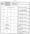
- FIG. 15 is a table explaining the cross-section of a 2D model to which a deformation induction portion 32 is applied
- FIG. 16 is a table showing the results of an experiment in which deformation patterns of a venting portion 31 is confirmed by performing 2D static analysis on the model in FIG. 15 .
- FIG. 15 shows a cross-section from the center of the housing cover 30 to one end thereof for each case.
- the housing cover 30 shown in FIG. 15 has a radius of about 21.6 mm, and the venting portion 31 is provided at a distance of about 14.9 mm from the center of the housing cover 30.
- the deformation induction portion 32 is provided in the area between the center of the housing cover 30 and a point placed at a distance of about 14.9 mm from the center. Converted to ratios, the venting portion 31 is provided at a point corresponding to about 70% of the radius of the housing cover 30 from the center of the housing cover 30, and the deformation induction portion 32 is provided in the area between the center point of the housing cover 30 and a point corresponding to 70% of the radius of the housing cover 30.
- venting pressure is highest in the conventional housing cover 30 without the deformation induction portion 32 and that the vent pressure is lower in the case where the deformation induction portion 32 is provided in the area toward the center in the radial direction, based on the venting portion 31.
- the vent pressure may be reduced. If the vent pressure is low, gas venting may immediately follow the thermal event occurring, which may be advantageous in safety. In addition, if the gas venting occurs immediately, the time required for deformation of the flange portion may be reduced, thereby minimizing deformation of the flange portion. Accordingly, the risk of leakage of electrolyte or the like may be reduced. As a result, according to the present disclosure, it is possible to adjust the vent pressure by the application of the deformation induction portion 32. Additionally, according to the present disclosure, the flatness of the flange portion may be secured.
- the venting pressure acting on the venting portion 31 is the lowest in the case where the deformation induction portion 32 is provided between a point place at a distance of about 5 mm from the center of the housing cover 30 (the point corresponding to about 23% of the radius of the housing cover 30 from the center of the housing cover 30) and a point place at a distance of about 13 mm therefrom (the point corresponding to about 60% of the radius of the housing cover 30 from the center of the housing cover 30).
- the venting pressure acting on the venting portion 31 is even lower than that in the case where the deformation induction portion 32 is provided between a point place at a distance of about 5 mm from the center of the housing cover 30 (the point corresponding to about 23% of the radius of the housing cover 30 from the center of the housing cover 30) and a point place at a distance of about 10 mm therefrom (the point corresponding to about 46% of the radius of the housing cover 30 from the center of the housing cover 30).
- venting pressure acting on the venting portion 31 is the lowest in the case where the deformation induction portion 32 is provided in both directions at a point place at a distance of about 10 mm from the center of the housing cover 30 (the point corresponding to about 46% of the radius of the housing cover 30 from the center of the housing cover 30), in this case, the maximum stress acts on the deformation induction portion 32, instead of the venting portion 31. That is, in this case, the deformation induction portion 32 is likely to break. Therefore, it is important that the venting portion 31 is provided at a position where the maximum stress occurs and that the deformation induction portion 32 is provided within an appropriate range to lower the vent pressure.
- the collector 40 according to an embodiment of the present disclosure is accommodated inside the battery housing 20, is electrically connected to the electrode assembly 10, and is also electrically connected to the battery housing 20. That is, the collector 40 electrically connects the electrode assembly 10 and the battery housing 20.
- FIG. 17 is a diagram illustrating the battery pack 3 including the battery cell 1 in FIG. 1 .
- the battery pack 3 includes a battery assembly in which a plurality of battery cells 1 according to an embodiment of the present disclosure described above is electrically connected and a pack housing 2 accommodating the same.
- the components such as a bus bar for electrical connection, a cooling unit, and power terminals are omitted from the drawings of the present disclosure.
- the battery pack 3 may further include the elements of the battery pack 3, which are known at the time of filing the present disclosure, such as a BMS, a pack case, a relay, a current sensor, and the like.
- FIG. 18 is a diagram illustrating the vehicle 5 including the battery pack 3 in FIG. 17 .
- the vehicle 5 may be, for example, an electric vehicle, a hybrid vehicle, or a plug-in hybrid vehicle, and include the battery pack 3 according to an embodiment of the present disclosure.
- the vehicle 5 includes a four-wheeled vehicle and a two-wheeled vehicle.
- the vehicle 5 operates by receiving power from the battery pack 3 according to an embodiment of the present disclosure.
- the vehicle 5 according to the present disclosure may further include various other elements included in the vehicle 5 in addition to the battery pack 3.
- the vehicle 5 according to the present disclosure may further include a vehicle body, a motor, a control device such as an electronic control unit (ECU), and the like, in addition to the battery pack 3 according to the present disclosure.
- ECU electroniceee control unit
- the present disclosure may minimize deformation of the area around the venting portion 31 by applying the deformation induction portion 32. In other words, leakage of electrolyte due to slippage of the flange portion may be suppressed.
- the flatness of the housing cover 30 may be secured by suppressing bending of the flat portion by applying the deformation induction portion 32.
- vent pressure may be expected to be controlled by the double notch structure of the venting portion 31 and the deformation induction portion 32.
Landscapes
- Chemical & Material Sciences (AREA)
- Chemical Kinetics & Catalysis (AREA)
- Electrochemistry (AREA)
- General Chemical & Material Sciences (AREA)
- Sealing Battery Cases Or Jackets (AREA)
- Gas Exhaust Devices For Batteries (AREA)
Abstract
Description
- The present disclosure relates to a battery cell, a battery pack, and a vehicle including the same.
- The present application claims priority to
Korean Patent Application No. 10-2022-0183384 filed on December 23, 2022 Korean Patent Application No. 10-2023-0064622 filed on May 18, 2023 - Secondary batteries, which are easy to apply depending on the product group and have electrical characteristics such as high energy density and the like, are generally used in electric vehicles (EVs) or hybrid electric vehicles (HEVs) that are driven by an electrical drive source, as well as in portable devices. These secondary batteries are attracting attention as a new energy source for improving eco-friendliness and energy efficiency because they have the primary advantage of being able to dramatically reduce the use of fossil fuels and no by-product is generated due to energy use.
- Current secondary batteries widely used include lithium ion batteries, lithium polymer batteries, nickel cadmium batteries, nickel hydrogen batteries, nickel zinc batteries, and the like. The operating voltage of this unit secondary battery cell, that is, the unit battery cell, is approximately 2.5V to 4.5V. Therefore, when an output voltage higher than this is required, a battery pack may be configured by connecting a plurality of battery cells in series. In addition, a battery pack may be configured by connecting multiple battery cells in parallel depending on the charge/discharge capacity required for the battery pack. Accordingly, the number of battery cells included in the battery pack may be set in various ways depending on the required output voltage or charge/discharge capacity.
- Meanwhile, in a BDCR (beading/crimping portion) structure of a cylindrical battery cell, a venting portion serves to lower the internal pressure of the battery cell caused by gas through breakage of a notch provided in the venting portion in the process in which the internal pressure of the battery cell increases, thereby preventing fire.
- However, if the pressure inside the battery cell rises, the housing cover bends, so that lifting occurs between the housing cover and a gasket surrounding the housing cover, resulting in slippage of the housing cover, so there is a risk of leakage of electrolyte and the like from the battery cell.
- However, if the thickness of the notch is gradually reduced to control the venting time, there is a problem with risks related to processing efficiency and product safety.
- The present disclosure has been designed to solve the problems of the related art, and therefore the present disclosure is intended to minimize deformation in the shape of a housing cover by providing a separate deformation induction portion, instead of the venting portion, and preferentially inducing deformation of the deformation induction portion.
- In another aspect, the present disclosure is intended to suppress bending of a flat portion of a housing cover by applying a deformation induction portion, thereby securing flatness of the housing cover.
- More specifically, the present disclosure is intended to prevent electrolyte from leaking due to slippage of the housing cover by preventing the generation of a gap between the housing cover and a gasket surrounding the housing cover.
- In another aspect, the present disclosure is intended to control the time at which the venting portion breaks by applying a deformation induction portion.
- However, the technical problems that the present disclosure seeks to solve are not limited to the above-mentioned problems, and other problems not mentioned above will be clearly understood by those skilled in the art from the description of the invention described below.
- According to the present disclosure, there is provided a battery cell including: an electrode assembly that includes a first electrode, a second electrode, and a separator interposed therebetween; a battery housing configured to receive the electrode assembly through an opening formed on one side; and a housing cover that includes a venting portion configured to cover the opening and break if internal pressure of the battery housing increases to a predetermined level or more, and a deformation induction portion spaced a predetermined distance apart from the venting portion in the radial direction and provided inward from the venting portion in the radial direction.
- In one aspect of the present disclosure, the deformation induction portion may be configured to induce the housing cover to be preferentially deformed in an area where the deformation induction portion is formed if the internal pressure of the battery housing increases to a predetermined level or more.
- In another aspect of the present disclosure, the deformation induction portion may form a circular closed loop.
- In another aspect of the present disclosure, the venting portion and the deformation induction portion may be provided in a flat portion, which is a central flat area of the housing cover.
- Preferably, the deformation induction portion may be provided inward from the venting portion in the radial direction.
- In another aspect of the present disclosure, the deformation induction portion may be provided in an area between the center point of the housing cover and a point corresponding to 70% of the radius of the housing cover.
- Preferably, the deformation induction portion may be provided in an area between a point corresponding to 20% of the radius of the housing cover and a point corresponding to 60% of the radius of the housing cover.
- In another aspect of the present disclosure, the radial length between the deformation induction portion and the venting portion may be 10 to 50% of the radial length of the housing cover.
- In another aspect of the present disclosure, the deformation induction portion may include at least one of an upper deformation induction portion provided on an upper surface of the housing cover and a lower deformation induction portion provided on a lower surface of the housing cover.
- Preferably, the deformation induction portion may include an upper deformation induction portion provided on an upper surface of the housing cover and a lower deformation induction portion provided on a lower surface of the housing cover.
- In another aspect of the present disclosure, the thickness of the housing cover in the area where the deformation induction portion is formed may be configured to be greater than the thickness of the housing cover in the area where the venting portion is formed.
- In another aspect of the present disclosure, the upper deformation induction portion and the lower deformation induction portion may be provided in a staggered state.
- Meanwhile, the present disclosure provides a battery pack including at least one battery cell according to the embodiments described above.
- Furthermore, the present disclosure provides a vehicle including at least one battery pack according to the embodiments described above.
- According to the present disclosure, it is possible to minimize deformation in the shape of a housing cover by providing a separate deformation induction portion, instead of the venting portion, and preferentially inducing deformation of the deformation induction portion.
- In another aspect, according to the present disclosure, it is possible to secure flatness of a housing cover by suppressing bending of a flat portion of the housing cover by application of a deformation induction portion.
- More specifically, according to the present disclosure, it is possible to prevent electrolyte from leaking due to slippage of the housing cover by preventing the generation of a gap between the housing cover and a gasket surrounding the housing cover.
- In another aspect, according to the present disclosure, it is possible to control the time at which the venting portion breaks by applying a deformation induction portion.
- However, the effects obtainable from the present disclosure are not limited to the above-mentioned effects, and other effects not mentioned above will be clearly understood by those skilled in the art from the description of the invention described below.
- The accompanying drawings illustrate a preferred embodiment of the present disclosure and, together with the detailed description of the invention, serve to provide further understanding of the technical idea of the present disclosure, and thus, the present disclosure is not construed as being limited to the drawings.
-
FIG. 1 is a diagram illustrating a battery cell according to an embodiment of the present disclosure. -
FIG. 2 is a longitudinal cross-sectional and perspective view inFIG. 1 . -
FIG. 3 is a longitudinal cross-sectional view of the battery cell inFIG. 1 . -
FIG. 4 is a diagram illustrating a housing cover according to an embodiment of the present disclosure. -
FIG. 5 is a diagram illustrating a housing cover in a comparative example of the present disclosure. -
FIG. 6 is a diagram illustrating the process in which the housing cover inFIG. 5 receives pressure by venting gas. -
FIG. 7 is a diagram illustrating a housing cover according to an embodiment of the present disclosure. -
FIG. 8 is a diagram illustrating a process in which the housing cover inFIG. 7 receives pressure by venting gas. -
FIG. 9 is a diagram illustrating the specific shape of a housing cover according to an embodiment of the present disclosure. -
FIG. 10 is a diagram illustrating a housing cover according to another embodiment of the present disclosure. -
FIG. 11 is a diagram illustrating a housing cover according to another embodiment of the present disclosure. -
FIG. 12 is a diagram illustrating a housing cover according to another embodiment of the present disclosure. -
FIG. 13 is a diagram illustrating the shape of a deformation induction portion according to an embodiment of the present disclosure. -
FIG. 14 is a diagram illustrating the shape of a deformation induction portion according to another embodiment of the present disclosure. -
FIG. 15 is a table explaining the cross-section of a 2D model to which a deformation induction portion is applied. -
FIG. 16 is a table showing the results of an experiment in which deformation patterns of a venting portion is confirmed by performing 2D static analysis on the model inFIG. 15 . -
FIG. 17 is a diagram illustrating a battery pack including the battery cell inFIG. 1 . -
FIG. 18 is a diagram illustrating a vehicle including the battery pack inFIG. 17 . - Hereinafter, preferred embodiments of the present disclosure will be described in detail with reference to the accompanying drawings. Prior to the description, it should be understood that the terms used in the specification and the appended claims should not be construed as limited to general and dictionary meanings, but interpreted based on the meanings and concepts corresponding to technical aspects of the present disclosure on the basis of the principle that the inventor is allowed to define terms appropriately for the best explanation. Therefore, the configurations proposed in the embodiments and drawings of this specification indicate only the most preferable embodiment of the present disclosure and do not represent all technical ideas of the present disclosure, so it should be understood that various equivalents and modifications could be made thereto at the time of filing the application.
- Additionally, to aid understanding of the present disclosure, the accompanying drawings are not drawn to real scale and the dimensions of some elements may be exaggerated. In addition, the same reference numerals may indicate the same elements between different embodiments.
- Stating that two objects to be compared are the same means that they are "substantially the same." Therefore, "substantially the same" may include the case having a deviation that is considered low in the art, for example, a deviation of less than 5%. In addition, a parameter that is uniform in a certain area may indicate that it is uniform from the average perspective.
- Although "first," "second," etc. are used to describe various elements, these elements are not limited to these terms. These terms are only used to distinguish one element from another element, and unless otherwise stated, a first element may also be a second element.
- Throughout the specification, unless otherwise stated, respective elements may include a single or a plurality of elements.
- Configuration in which an element is disposed "in the upper portion (or lower portion)" or "at the top (or bottom)" of a target element may indicate that the element may be disposed in contact with the upper surface (or lower surface) of the target element and that another element may be interposed between the target element and the element disposed at the top (or bottom) of the target element.
- Additionally, the expression "an element is 'connected,' 'coupled,' or `fastened' to another element" should be understood that the elements may be directly connected or fastened to each other, and that another element may be "interposed" between the elements or that the elements may be "connected," "coupled," or "fastened" through other elements.
- Throughout the specification, "A and/or B", unless otherwise stated, may denote A or B or A and B, and "C to D", unless otherwise stated, may denote "equal to or greater than C and equal to or less than D."
- For convenience of explanation, in this specification, the longitudinal direction of a winding axis of an
electrode assembly 10 wound in a jellyroll shape will be referred to as an "axial direction (Y)". In addition, the direction surrounding the winding axis will be referred to as a "circumferential direction(X)." In addition, the direction approaching or moving away from the winding axis will be referred to as a "radial direction." Among these, the direction approaching the winding axis is called a "centripetal direction," and the direction moving away from the winding axis is called a "centrifugal direction." -
FIG. 1 is a diagram illustrating abattery cell 1 according to an embodiment of the present disclosure, andFIG. 2 is a longitudinal cross-sectional and perspective view inFIG. 1 .FIG. 3 is a longitudinal cross-sectional view of thebattery cell 1 inFIG. 1 . - Referring to
FIG. 1 , thebattery cell 1 according to an embodiment of the present disclosure includes anelectrode assembly 10, abattery housing 20, and ahousing cover 30. Thebattery cell 1 may further include acollector 40. The present disclosure is not limited to a specific type of battery, and may be applied to other types of batteries, such as a prismatic battery. - Referring to
FIGS. 2 and3 , theelectrode assembly 10 includes afirst electrode tab 11 and asecond electrode tab 12. Specifically, theelectrode assembly 10 includes a first electrode, a second electrode, and a separator interposed therebetween. Theelectrode assembly 10 has a structure in which a first electrode and a second electrode are wound around a winding axis while a separator is interposed therebetween, thereby defining a core and an outer circumferential surface. That is, theelectrode assembly 10 applied to the present disclosure may be a jellyroll-type electrode assembly 10. In this case, an additional separator may be provided on the outer circumferential surface of theelectrode assembly 10 to insulate the same from thebattery housing 20. Theelectrode assembly 10 may have a winding structure well known in the art without limitations. - Meanwhile, in the present disclosure, any active material known in the art may be used, without limitations, as the positive electrode active material coated on the positive electrode plate and the negative electrode active material coated on the negative electrode plate.
- Referring to
FIGS. 1 and2 , thebattery housing 20 is a substantially cylindrical container having an opening formed on one side thereof, and is made of a conductive metal material. In general, the side face of thebattery housing 20 and the bottom face opposite the opening are integrally formed. That is, thebattery housing 20 is generally configured such that the top thereof in the height direction is open and the bottom is closed. The bottom face of thebattery housing 20 may be configured in a substantially flat shape. Thebattery housing 20 receives theelectrode assembly 10 through the opening formed on one side in the height direction. Thebattery housing 20 may also receive an electrolyte through the opening. - The
battery housing 20 may have abeading portion 21 formed at an end adjacent to the opening provided at the top of thebattery housing 20. Thebattery housing 20 may further include a crimpingportion 22 formed on thebeading portion 21. Thebeading portion 21 may be configured such that the outer circumferential surface of thebattery housing 20 is press-fitted to a predetermined depth. More specifically, thebeading portion 21 may be configured to be press-fitted inward in the area between the opening formed on one side of thebattery housing 20 and an accommodation portion that accommodates theelectrode assembly 10. - The
beading portion 21 is formed above theelectrode assembly 10. The inner diameter of thebattery housing 20 in the area where thebeading portion 21 is formed is smaller than the diameter of theelectrode assembly 10. - The
beading portion 21 provides a support surface on which thehousing cover 40 is seated. In addition, thebeading portion 21 may provide a support surface on which at least a portion of the edge of thecollector 40 is seated and coupled. That is, at least a portion of the edge of thecollector 40 of the present disclosure and/or the edge of thehousing cover 30 may be seated on the upper surface of thebeading portion 21. In order to stably support at least a portion of the edge of thecollector 40 and/or the edge of thehousing cover 30, the upper surface of thebeading portion 21 may be configured to extend in a direction approximately parallel to the bottom face of thebattery housing 20, that is, in a direction approximately perpendicular to the side wall of thebattery housing 20. - The
beading portion 21 may prevent theelectrode assembly 10, which may have a size approximately corresponding to the inner diameter of thebattery housing 20, from coming out through the opening formed at the top of thebattery housing 20 and serve as a support portion on which thehousing cover 30 is seated. Theupper beading portion 21 may function as a support portion for fixing thecollector 40, a sealing gasket G1, and the like, as well as thehousing cover 30. - The crimping
portion 22 is formed on the top of thebeading portion 21. The crimpingportion 22 is configured to extend and bend to surround the edge of thehousing cover 30 disposed above thebeading portion 21. Such a configuration of the crimpingportion 22 may fix thehousing cover 30 onto thebeading portion 21. - Referring to
FIGS. 1 to 3 , thehousing cover 30 covers the opening formed on one side of thebattery housing 20. Thehousing cover 30 may be fixed by the crimpingportion 22 formed on the top of thebattery housing 20. In this case, a sealing gasket G1 may be interposed between thebattery housing 20 and thehousing cover 30 and between thecollector 40 and thehousing cover 30 to improve the fixing force and the airtightness of thebattery housing 20. In this case, a contact portion 33a and/or a second contact portion may be interposed between the beadingportion 21 of thebattery housing 20 and the sealing gasket G1. The contact portion 33a and/or the second contact portion interposed between the beadingportion 21 and the sealing gasket G1 as described above may be fixed by bending the crimpingportion 22 extending upwards from thebeading portion 21. - The
housing cover 30 may have a substantially circular plate shape. More specifically, thehousing cover 30 may include a flat portion, which is a central flat area, a flange portion, which is an area surrounded by the sealing gasket G1 and/or the crimpingportion 22, and a connection portion that connects the flat portion and the flange portion. The flat portion and the flange portion may be configured to be approximately parallel to the bottom face of thebattery housing 20. Here, the central axis-directional position of the flat portion may be higher than the central axis-directional position of the flange portion. Accordingly, the connection portion may have an inclined shape to connect the flat portion and the flange portion. - Meanwhile, in the present disclosure, the
housing cover 30 is not a component that must function as a current path. Therefore, the sealing gasket G1 is not necessarily applied as long as the airtightness of the opening of thebattery housing 20 is secured by firmly fixing thebattery housing 20 and thehousing cover 30 by welding or fixing using other parts. - Referring to
FIGS. 1 to 3 , thehousing cover 30 includes a ventingportion 31 and adeformation induction portion 32. - Referring to
FIGS. 1 to 3 , the ventingportion 31 may be formed to prevent an increase in internal pressure due to gas generated inside thebattery housing 20. The ventingportion 31 may be configured to break when the internal pressure of thebattery housing 20 increases to a predetermined level or more. For example, the ventingportion 31 may be formed in a portion of thehousing cover 30, and may be a more vulnerable area in structure than the surrounding area so as to easily break when internal pressure is applied thereto. For example, the ventingportion 31 may be an area having a smaller thickness than the surrounding area. - That is, for some reason, a thermal event may occur inside the
battery cell 1 to generate venting gas, and the pressure inside thebattery housing 20 may increase due to the venting gas. At this time, the ventingportion 31, corresponding to the area that is more vulnerable in structure than the surrounding area so as to easily break when the internal pressure of thebattery cell 1 increases, may break when the venting gas is generated. - Referring to
FIGS. 1 to 3 , thedeformation induction portion 32 may be provided to be spaced a predetermined distance apart from the ventingportion 31 in the radial direction. Preferably, as shown inFIGS. 1 to 3 , it may be provided inward from the ventingportion 31 in the radial direction. Thedeformation induction portion 32 may be configured to be deformed if the internal pressure of thebattery housing 20 increases to a predetermined level or more. In particular, thedeformation induction portion 32 may be configured to induce thehousing cover 30 to be preferentially deformed in the area where thedeformation induction portion 32 is formed if the internal pressure of thebattery housing 20 increases to a predetermined level or more. - According to this configuration, stress may be applied to the
deformation induction portion 32 by the venting gas generated inside thebattery cell 1, thereby causing deformation of thedeformation induction portion 32. Accordingly, shape deformation of the ventingportion 31 may be minimized. Accordingly, deformation of the flange portion may be suppressed to prevent electrolyte or the like from leaking out of thebattery cell 1. -
FIG. 4 is a diagram illustrating ahousing cover 30 according to an embodiment of the present disclosure. - Referring to
FIGS. 1 to 4 , the ventingportion 31 may be configured to form a substantially circular closed loop. Accordingly, if venting gas is ejected from the inside of thebattery cell 1 so that internal pressure is applied to thehousing cover 30 in the upward direction, the ventingportion 31 may break, and the inner area of the circular closed loop of thehousing cover 30 may rupture. Accordingly, venting may be effectively performed. - Meanwhile, referring to
FIGS. 1 to 4 , thedeformation induction portion 32 may be configured to form a substantially circular closed loop. Accordingly, if venting gas is ejected from the inside of thebattery cell 1 so that internal pressure is applied to thehousing cover 30 in the upward direction, thedeformation induction portion 32 may be deformed. At this time, since thedeformation induction portion 32 is configured to form an approximately circular closed loop, thedeformation induction portion 32 may be easily deformed. - In another aspect of the present disclosure, the venting
portion 31 and thedeformation induction portion 32 may be provided in a flat portion, which is a central flat area of thehousing cover 30. - For example, referring to
FIGS. 1 to 4 , it can be seen that thedeformation induction portion 32 and the ventingportion 31 are provided in the flat portion of thehousing cover 30. - According to this structure, since the venting
portion 31 breaks and thedeformation induction portion 32 is deformed and breaks within the flat area, deformation in the shape of the flange portion or the connection portion may be minimized. In particular, it is possible to prevent the flange portion from being deformed from a shape substantially parallel to the bottom face of thebattery housing 20 to an inclined shape. As a result, deformation of the flange portion may be suppressed to prevent electrolyte or the like from leaking out of thebattery cell 1. - In another aspect of the present disclosure, the
deformation induction portion 32 may be provided inward from the ventingportion 31 in the radial direction. This will be described in detail below with reference toFIGS. 5 and 6 illustrating a comparative example of the present disclosure andFIGS. 7 and 8 illustrating an embodiment of the present disclosure. -
FIG. 5 is a diagram illustrating ahousing cover 30 in a comparative example of the present disclosure, andFIG. 6 is a diagram illustrating the process in which thehousing cover 30 inFIG. 5 receives pressure by venting gas. Meanwhile,FIG. 7 is a diagram illustrating ahousing cover 30 according to an embodiment of the present disclosure, andFIG. 8 is a diagram illustrating a process in which thehousing cover 30 inFIG. 7 receives pressure by venting gas. - Referring to
FIGS. 5 and 6 , theconventional housing cover 30 includes only a ventingportion 31, excluding adeformation induction portion 32. According to this structure, if the internal pressure of thebattery cell 1 increases due to venting gas generated inside thebattery cell 1, stress is concentrated in the ventingportion 31, causing fracture. However, in the process of fracture of the ventingportion 31, thehousing cover 30 may be bent upwards under pressure, and at this time, it may become inclined in both directions, as shown inFIG. 6 , based on the ventingportion 31. Accordingly, the connection portion and the flange portion are also affected, so that the connection portion and the flange portion are deformed to be inclined at a predetermined angle with the bottom face of thebattery housing 20. In particular, as the flange portion is deformed to be inclined at a predetermined angle with the bottom face of thebattery housing 20, a gap may be produced between the flange portion and the sealing gasket G1, which eventually causes electrolyte or the like to leak out of thebattery cell 1. - On the other hand, the
housing cover 30 of the present disclosure includes a ventingportion 31 and adeformation induction portion 32 located to be spaced a predetermined distance apart from the ventingportion 31 in the radial direction. In this case, as shown inFIG. 7 , thedeformation induction portion 32 may be provided inward from the ventingportion 31 in the radial direction. - Referring to
FIG. 7 , for example, thedeformation induction portion 32 may be configured to be recessed inward from the surface of thehousing cover 30. For example, thedeformation induction portion 32 may be configured in the form of a groove or notch. Meanwhile, the recessed shape is not limited to a U-shape or V-shape, and the scope of the present disclosure encompasses any structure recessed inward from the surface of thehousing cover 30. Furthermore, the shape of thedeformation induction portion 32 is not limited to the groove or notch, and thedeformation induction portion 32 of the present disclosure encompasses any configuration that is configured to be weaker than the surrounding area and to be more easily deformed than the surrounding area. - According to this structure, even if the internal pressure of the
battery cell 1 increases, stress is applied to thedeformation induction portion 32, as well as the ventingportion 31. Accordingly, the shape of thedeformation induction portion 32 may be changed. In particular, in the case where thedeformation induction portion 32 is provided inward from the ventingportion 31 in the radial direction, thedeformation induction portion 32 may be dominantly deformed. In other words, the configuration in which thedeformation induction portion 32 is provided inward from the ventingportion 31 in the radial direction may maximize the deformation of thedeformation induction portion 32. In other words, according to the present disclosure, since thedeformation induction portion 32, instead of the ventingportion 31, is bent, the bending of the ventingportion 31 may be suppressed. Accordingly, deformation may be prevented in the surrounding area of the ventingportion 31, in particular, the flange portion. As a result, the flange portion is not deformed, thereby reducing the risk of leakage of electrolyte or the like. -
FIG. 9 is a diagram illustrating the specific shape of ahousing cover 30 according to an embodiment of the present disclosure. - In another aspect of the present disclosure, the
deformation induction portion 32 may be provided in the area between the center point of thehousing cover 30 and a point corresponding to about 70% of the radius of thehousing cover 30. - For example, the
housing cover 30 shown inFIG. 9 according to an embodiment of the present disclosure has a radius of about 21.6 mm, and the ventingportion 31 is provided at a distance of about 14.9 mm from the center of thehousing cover 30. Thedeformation induction portion 32 is provided in the area between the center of thehousing cover 30 and a point placed at a distance of about 14.9 mm from the center. Converted to ratios, the ventingportion 31 is provided at a point corresponding to about 70% of the radius of thehousing cover 30 from the center of thehousing cover 30, and thedeformation induction portion 32 is provided in the area between the center point of thehousing cover 30 and a point corresponding to 70% of the radius of thehousing cover 30. That is, according to the above configuration, thedeformation induction portion 32 may be provided inward from the ventingportion 31 in the radial direction. - As described above, according to the structure in which the
deformation induction portion 32 is provided in the area between the center point of thehousing cover 30 and the point corresponding to 70% of the radius of thehousing cover 30, it is possible to secure flatness of the flange portion, compared to the case where thedeformation induction portion 32 is provided outside the point corresponding to 70% of the radius of thehousing cover 30. If thedeformation induction portion 32 is provided outside the above point, thedeformation induction portion 32 is located outwards from the ventingportion 31, so that thedeformation induction portion 32 may receive a greater stress than the ventingportion 31. That is, since thedeformation induction portion 32 where deformation occurs is closer to the flange portion, the deformation of the flange portion may become more severe. In addition, since a greater stress is applied to thedeformation induction portion 32 than to the ventingportion 31, breakage may occur in thedeformation induction portion 32 rather than the ventingportion 31. On the other hand, according to the present disclosure, since thedeformation induction portion 32 where deformation occurs is far away from the flange portion, deformation of the flange portion may be suppressed. - Preferably, the
deformation induction portion 32 may be provided in the area between a point corresponding to approximately 20% of the radius of thehousing cover 30 and a point corresponding to approximately 60% of the radius of thehousing cover 30. That is, the radial length between thedeformation induction portion 32 and the ventingportion 31 may be about 10 to 50% of the radial length of thehousing cover 30. - For example, referring to the
housing cover 30 shown inFIG. 9 according to an embodiment of the present disclosure, the lowest venting pressure acting on the ventingportion 31 may be obtained in the case where thedeformation induction portion 32 is provided in the area between a point corresponding to about 20% of the radius of thehousing cover 30 from the center of thehousing cover 30 and a point corresponding to about 60% of the radius of thehousing cover 30 from the center of thehousing cover 30. In this case, the ventingportion 31 may be provided at a point corresponding to about 70% of the radius of thehousing cover 30 from the center of thehousing cover 30, so that the radial length between thedeformation induction portion 32 and the ventingportion 31 may be about 10 to 50% of the radial length of thehousing cover 30. - More preferably, if the
deformation induction portion 32 is provided in the area between a point corresponding to about 23% of the radius of thehousing cover 30 from the center of thehousing cover 30 and a point corresponding to about 46% of the radius of thehousing cover 30 from the center of thehousing cover 30, the vent pressure acting on the ventingportion 31 may be secured to be even lower than that. - That is, according to the present disclosure, it is possible to minimize deformation of the area around the venting
portion 31 by separately providing thedeformation induction portion 32, instead of the ventingportion 31, and inducing deformation of thedeformation induction portion 32. That is, the leakage of electrolyte due to slippage of the flange portion may be suppressed. In addition, according to the present disclosure, the flatness of thehousing cover 30 may be secured by suppressing bending of the flat portion by applying thedeformation induction portion 32. - Furthermore, according to the present disclosure, it is possible to control the time at which the venting
portion 31 breaks using thedeformation induction portion 32. In other words, vent pressure may be expected to be controlled by a dual structure of the ventingportion 31 and thedeformation induction portion 32. - For reference, although the
housing cover 30 of a specific configuration has been described by way of example to explain an embodiment of the present disclosure in this specification, the scope of the present disclosure is not limited to thehousing cover 30 of the specific configuration, and surely encompasses housing covers 30 of other configurations in which the ventingportion 31 and/or thedeformation induction portion 32 are located at the same ratio to each other as that of the above embodiment. -
FIG. 10 is a diagram illustrating ahousing cover 30 according to another embodiment of the present disclosure, andFIG. 11 is a diagram illustrating ahousing cover 30 according to another embodiment of the present disclosure. - Since the
housing cover 30 according to the present embodiment is similar to thehousing cover 30 in the previous embodiment, redundant descriptions of elements that are substantially the same as or similar to those in the previous embodiment will be omitted, and hereinafter, a description will be made based on the differences therefrom. - According to one aspect of the present disclosure, the
deformation induction portion 32 may include at least one of an upper deformation induction portion N1 provided on the upper surface of thehousing cover 30 and a lower deformation induction portion N2 provided on the lower surface of thehousing cover 30. - For example, the
deformation induction portion 32 may include only an upper deformation induction portion N1 provided on the upper surface of thehousing cover 30, as shown inFIG. 10 . As another embodiment, thedeformation induction portion 32 may include only the lower deformation induction portion N2 provided on the lower surface of thehousing cover 30, as shown inFIG. 11 . As another embodiment, thedeformation induction portion 32 may include both an upper deformation induction portion N1 provided on the upper surface of thehousing cover 30 and a lower deformation induction portion N2 provided on the lower surface of thehousing cover 30, as shown inFIG. 7 . - In the case where the
deformation induction portions 32 are provided on both surfaces of thehousing cover 30, the vent pressure may be minimized. Meanwhile, in the case where thedeformation induction portion 32 is provided only on the lower surface of thehousing cover 30, the vent pressure may be maximized. As a result, the vent pressure may decrease depending on the formation position of thedeformation induction portion 32, as follows. - When the
deformation induction portion 32 is provided only on the lower surface > when thedeformation induction portion 32 is provided only on the upper surface > when thedeformation induction portion 32 is provided on both surfaces - Meanwhile, if the vent pressure is low, gas venting may immediately follow the thermal event occurring, which may be advantageous in safety. In addition, if the gas venting occurs immediately, the time required for deformation of the flange portion is reduced, thereby minimizing deformation of the flange portion. Accordingly, the risk of leakage of electrolyte or the like may be reduced. As a result, according to the present disclosure, it is possible to adjust the vent pressure by the application of the
deformation induction portion 32. Additionally, according to the present disclosure, the flatness of the flange portion may be secured. -
FIG. 12 is a diagram illustrating ahousing cover 30 according to another embodiment of the present disclosure. - In one aspect of the present disclosure, the thickness of the
housing cover 30 in the area where thedeformation induction portion 32 is formed may be greater than the thickness of thehousing cover 30 in the area where the ventingportion 31 is formed. - For example, referring to
FIG. 12 , the thickness of the area where thedeformation induction portion 32 is formed may be greater than the thickness of the area where the ventingportion 31 is formed. In general, the size of the notch, that is, the thickness between notches, may be adjusted to control the venting time. If the thickness between notches is small, the ventingportion 31 is likely to break, and if the thickness between notches is large, the ventingportion 31 is not likely to break. Therefore, when constructing thedeformation induction portion 32, the break time may be controlled by adjusting the thickness between notches. - According to the present disclosure, since the thickness of the area where the
deformation induction portion 32 is formed is greater than the thickness of the area where the ventingportion 31 is formed, the ventingportion 31 may more easily break than thedeformation induction portion 32. Accordingly, even when pressure is generated due to the venting gas, the ventingportion 31, instead of thedeformation induction portion 32, preferentially breaks. - The
deformation induction portion 32 may be deformed in its shape before and after the breakage of the ventingportion 31, thereby playing a role of controlling the break time of the ventingportion 31. For example, when stress acts on thedeformation induction portion 32, the surrounding area of thedeformation induction portion 32 may be deformed from a flat shape to a bent shape, based on thedeformation induction portion 32. Accordingly, the surrounding area of thedeformation induction portion 32 may be inclined in both directions with respect to thedeformation induction portion 32. That is, since the shape of thedeformation induction portion 32, instead of the shape of the ventingportion 31, is deformed, the ventingportion 31 may remain in its own shape, thereby suppressing the lifting of the flange portion. As a result, this may prevent electrolyte or the like from leaking out of thebattery cell 1. -
FIG. 13 is a diagram illustrating the shape of adeformation induction portion 32 according to an embodiment of the present disclosure, andFIG. 14 is a diagram illustrating the shape of adeformation induction portion 32 according to another embodiment of the present disclosure. - Since the
housing cover 30 according to the present embodiment is similar to thehousing cover 30 in the previous embodiment, redundant descriptions of elements that are substantially the same as or similar to those in the previous embodiment will be omitted, and hereinafter, a description will be made based on the differences therefrom. - Referring to
FIG. 13 , thedeformation induction portion 32 may include an upper deformation induction portion N1 provided on the upper surface of thehousing cover 30 and a lower deformation induction portion N2 provided on the lower surface of thehousing cover 30. As another embodiment of the present disclosure, as shown inFIG. 14 , the upper deformation induction portion N1 and the lower deformation induction portion N2 may be provided in a staggered state. - According to the structure shown in
FIG. 14 , since the upper deformation induction portion N1 and the lower deformation induction portion N2 are provided in a staggered state, shear stress may be dominant in the area between the upper deformation induction portion N1 and the lower deformation induction portion N2. On the other hand, if the upper deformation induction portion N1 and the lower deformation induction portion N2 are provided on the same line in thehousing cover 30 as shown inFIG. 13 , tensile stress may be dominant in the area between the upper deformation induction portion N1 and the lower deformation induction portion N2. Under the same pressure acting on the area between the upper deformation induction portion N1 and the lower deformation induction portion N2, deformation occurs more easily when shear stress is applied, compared to when tensile stress is applied. Therefore, according to the present disclosure, thedeformation induction portion 32 is easily deformed even if a lower vent pressure is applied. Alternatively, since the upper deformation induction portion N1 and the lower deformation induction portion N2 are in the staggered state, it may be possible to secure the same amount of deformation with a small amount of formation. As a result, a reduction in the amount of deformation may reduce damage to the mold, so that the lifespan of thehousing cover 30 may be expected to increase. -
FIG. 15 is a table explaining the cross-section of a 2D model to which adeformation induction portion 32 is applied, andFIG. 16 is a table showing the results of an experiment in which deformation patterns of a ventingportion 31 is confirmed by performing 2D static analysis on the model inFIG. 15 . -
FIG. 15 shows a cross-section from the center of thehousing cover 30 to one end thereof for each case. For example, thehousing cover 30 shown inFIG. 15 has a radius of about 21.6 mm, and the ventingportion 31 is provided at a distance of about 14.9 mm from the center of thehousing cover 30. Thedeformation induction portion 32 is provided in the area between the center of thehousing cover 30 and a point placed at a distance of about 14.9 mm from the center. Converted to ratios, the ventingportion 31 is provided at a point corresponding to about 70% of the radius of thehousing cover 30 from the center of thehousing cover 30, and thedeformation induction portion 32 is provided in the area between the center point of thehousing cover 30 and a point corresponding to 70% of the radius of thehousing cover 30. - Referring to
FIGS. 15 and16 , it was confirmed that the venting pressure is highest in theconventional housing cover 30 without thedeformation induction portion 32 and that the vent pressure is lower in the case where thedeformation induction portion 32 is provided in the area toward the center in the radial direction, based on the ventingportion 31. - That is, as can be seen from the above results, according to the present disclosure to which the
deformation induction portion 32 is applied, the vent pressure may be reduced. If the vent pressure is low, gas venting may immediately follow the thermal event occurring, which may be advantageous in safety. In addition, if the gas venting occurs immediately, the time required for deformation of the flange portion may be reduced, thereby minimizing deformation of the flange portion. Accordingly, the risk of leakage of electrolyte or the like may be reduced. As a result, according to the present disclosure, it is possible to adjust the vent pressure by the application of thedeformation induction portion 32. Additionally, according to the present disclosure, the flatness of the flange portion may be secured. - Referring to
FIGS. 15 and16 , it was confirmed that, more preferably, the venting pressure acting on the ventingportion 31 is the lowest in the case where thedeformation induction portion 32 is provided between a point place at a distance of about 5 mm from the center of the housing cover 30 (the point corresponding to about 23% of the radius of thehousing cover 30 from the center of the housing cover 30) and a point place at a distance of about 13 mm therefrom (the point corresponding to about 60% of the radius of thehousing cover 30 from the center of the housing cover 30). In particular, it was confirmed that the venting pressure acting on the ventingportion 31 is even lower than that in the case where thedeformation induction portion 32 is provided between a point place at a distance of about 5 mm from the center of the housing cover 30 (the point corresponding to about 23% of the radius of thehousing cover 30 from the center of the housing cover 30) and a point place at a distance of about 10 mm therefrom (the point corresponding to about 46% of the radius of thehousing cover 30 from the center of the housing cover 30). - However, although the venting pressure acting on the venting
portion 31 is the lowest in the case where thedeformation induction portion 32 is provided in both directions at a point place at a distance of about 10 mm from the center of the housing cover 30 (the point corresponding to about 46% of the radius of thehousing cover 30 from the center of the housing cover 30), in this case, the maximum stress acts on thedeformation induction portion 32, instead of the ventingportion 31. That is, in this case, thedeformation induction portion 32 is likely to break. Therefore, it is important that the ventingportion 31 is provided at a position where the maximum stress occurs and that thedeformation induction portion 32 is provided within an appropriate range to lower the vent pressure. - Referring to
FIGS. 1 and2 , thecollector 40 according to an embodiment of the present disclosure is accommodated inside thebattery housing 20, is electrically connected to theelectrode assembly 10, and is also electrically connected to thebattery housing 20. That is, thecollector 40 electrically connects theelectrode assembly 10 and thebattery housing 20. -
FIG. 17 is a diagram illustrating thebattery pack 3 including thebattery cell 1 inFIG. 1 . - Referring to
FIG. 17 , thebattery pack 3 according to an embodiment of the present disclosure includes a battery assembly in which a plurality ofbattery cells 1 according to an embodiment of the present disclosure described above is electrically connected and apack housing 2 accommodating the same. For convenience of illustration, the components such as a bus bar for electrical connection, a cooling unit, and power terminals are omitted from the drawings of the present disclosure. That is, thebattery pack 3 may further include the elements of thebattery pack 3, which are known at the time of filing the present disclosure, such as a BMS, a pack case, a relay, a current sensor, and the like. -
FIG. 18 is a diagram illustrating thevehicle 5 including thebattery pack 3 inFIG. 17 . - Referring to
FIG. 18 , thevehicle 5 according to an embodiment of the present disclosure may be, for example, an electric vehicle, a hybrid vehicle, or a plug-in hybrid vehicle, and include thebattery pack 3 according to an embodiment of the present disclosure. Thevehicle 5 includes a four-wheeled vehicle and a two-wheeled vehicle. Thevehicle 5 operates by receiving power from thebattery pack 3 according to an embodiment of the present disclosure. Thevehicle 5 according to the present disclosure may further include various other elements included in thevehicle 5 in addition to thebattery pack 3. For example, thevehicle 5 according to the present disclosure may further include a vehicle body, a motor, a control device such as an electronic control unit (ECU), and the like, in addition to thebattery pack 3 according to the present disclosure. - According to various embodiments described above, even if gas venting occurs due to an abnormality in the
battery cell 1, the present disclosure may minimize deformation of the area around the ventingportion 31 by applying thedeformation induction portion 32. In other words, leakage of electrolyte due to slippage of the flange portion may be suppressed. In addition, according to the present disclosure, the flatness of thehousing cover 30 may be secured by suppressing bending of the flat portion by applying thedeformation induction portion 32. Furthermore, according to the present disclosure, it is possible to control the time at which the ventingportion 31 breaks using thedeformation induction portion 32. In other words, vent pressure may be expected to be controlled by the double notch structure of the ventingportion 31 and thedeformation induction portion 32. - Meanwhile, although terms indicating directions such as upper and lower are used in this specification, it is obvious to those skilled in the art that these terms are only for convenience of explanation and may vary depending on the location of the target object or the location of the observer.
- As described above, although the present disclosure has been described with reference to limited embodiments and drawings, the present disclosure is not limited thereto, and various modifications and variations are possible within the technical idea of the present disclosure and the scope of equivalence of the claims to be described below by those skilled in the art to which the present disclosure pertains.
-
- 5: Vehicle
- 3: Battery pack
- 2: Pack housing
- 1: Battery cell
- 10: Electrode assembly
- 11: First non-coated portion
- 12: Second non-coated portion
- H1: Winding hole
- 20: Battery housing
- 21: Beading portion
- 22: Crimping portion
- 30: Housing cover
- 31: Venting portion
- 32: Deformation induction portion
- N1: Upper deformation induction portion
- N2: Lower deformation induction portion
- G1: Sealing gasket
- 40: Collector
- H2: Collector hole
Claims (13)
- A battery cell comprising:an electrode assembly comprising a first electrode, a second electrode, and a separator interposed therebetween;a battery housing configured to receive the electrode assembly through an opening formed on one side; anda housing cover comprising a venting portion configured to cover the opening and break if internal pressure of the battery housing increases to a predetermined level or more, and a deformation induction portion spaced a predetermined distance apart from the venting portion in the radial direction and provided inward from the venting portion in the radial direction.
- The battery cell according to claim 1,
wherein the deformation induction portion is configured to induce the housing cover to be preferentially deformed in an area where the deformation induction portion is formed if the internal pressure of the battery housing increases to a predetermined level or more. - The battery cell according to claim 1,
wherein the deformation induction portion forms a circular closed loop. - The battery cell according to claim 1,wherein the venting portion and the deformation induction portionare provided in a flat portion, which is a central flat area of the housing cover.
- The battery cell according to claim 1,wherein the deformation induction portionis provided in an area between the center point of the housing cover and a point corresponding to 70% of the radius of the housing cover.
- The battery cell according to claim 1,wherein the deformation induction portionis provided in an area between a point corresponding to 20% of the radius of the housing cover and a point corresponding to 60% of the radius of the housing cover.
- The battery cell according to claim 1,wherein the radial length between the deformation induction portion and the venting portion is10 to 50% of the radial length of the housing cover.
- The battery cell according to claim 1,
wherein the deformation induction portion comprises at least one of an upper deformation induction portion provided on an upper surface of the housing cover and a lower deformation induction portion provided on a lower surface of the housing cover. - The battery cell according to claim 1,
wherein the deformation induction portion comprises an upper deformation induction portion provided on an upper surface of the housing cover and a lower deformation induction portion provided on a lower surface of the housing cover. - The battery cell according to claim 1,
wherein the thickness of the housing cover in the area where the deformation induction portion is formed is greater than the thickness of the housing cover in the area where the venting portion is formed. - The battery cell according to claim 9,
wherein the upper deformation induction portion and the lower deformation induction portion are provided in a staggered state. - A battery pack comprising at least one battery cell according to any one of claims 1 to 11.
- A vehicle comprising at least one battery pack according to claim 12.
Applications Claiming Priority (3)
| Application Number | Priority Date | Filing Date | Title |
|---|---|---|---|
| KR20220183384 | 2022-12-23 | ||
| KR1020230064622A KR20240101310A (en) | 2022-12-23 | 2023-05-18 | Battery cells, battery packs, and vehicles containing them |
| PCT/KR2023/017855 WO2024136118A1 (en) | 2022-12-23 | 2023-11-08 | Battery cell, battery pack, and vehicle comprising same |
Publications (2)
| Publication Number | Publication Date |
|---|---|
| EP4468495A1 true EP4468495A1 (en) | 2024-11-27 |
| EP4468495A4 EP4468495A4 (en) | 2025-06-11 |
Family
ID=91589300
Family Applications (1)
| Application Number | Title | Priority Date | Filing Date |
|---|---|---|---|
| EP23907404.0A Pending EP4468495A4 (en) | 2022-12-23 | 2023-11-08 | BATTERY CELL, BATTERY PACK AND VEHICLE COMPRISING SAME |
Country Status (5)
| Country | Link |
|---|---|
| EP (1) | EP4468495A4 (en) |
| JP (1) | JP2025524069A (en) |
| CN (1) | CN119096403A (en) |
| CA (1) | CA3246327A1 (en) |
| WO (1) | WO2024136118A1 (en) |
Cited By (1)
| Publication number | Priority date | Publication date | Assignee | Title |
|---|---|---|---|---|
| EP4597697A1 (en) * | 2024-01-23 | 2025-08-06 | Samsung Sdi Co., Ltd. | Secondary battery |
Family Cites Families (11)
| Publication number | Priority date | Publication date | Assignee | Title |
|---|---|---|---|---|
| JP5096671B2 (en) * | 2005-09-13 | 2012-12-12 | 日立マクセルエナジー株式会社 | Sealed prismatic battery |
| WO2013009148A2 (en) * | 2011-07-13 | 2013-01-17 | 주식회사 엘지화학 | Cylindrical rechargeable battery |
| KR101693292B1 (en) * | 2013-01-21 | 2017-01-05 | 삼성에스디아이 주식회사 | Rechargeable battery |
| KR20180018279A (en) * | 2016-08-11 | 2018-02-21 | 신흥에스이씨주식회사 | Cap assembly of excellent electrical safety for a secondary battery and the battery inclusive of the same |
| WO2018030836A1 (en) * | 2016-08-11 | 2018-02-15 | Shin Heung Energy & Electronic Co.,Ltd. | Cap assembly for secondary battery and secondary battery including the cap assembly |
| KR102263435B1 (en) * | 2017-09-13 | 2021-06-11 | 주식회사 엘지에너지솔루션 | Cylindrical Battery Cell Having no Beading Part |
| CN109216596A (en) * | 2018-08-09 | 2019-01-15 | 广东微电新能源有限公司 | A kind of battery |
| KR102517397B1 (en) * | 2018-11-28 | 2023-04-04 | 주식회사 엘지에너지솔루션 | Secondary battery |
| KR102854971B1 (en) | 2020-10-07 | 2025-09-04 | 교세라 가부시키가이샤 | Jig for clamping, method for manufacturing jig for clamping, and cleaning device |
| KR102821618B1 (en) * | 2020-12-24 | 2025-06-16 | 주식회사 엘지에너지솔루션 | Secondary battery and manufacturing method of the same |
| PL4047703T3 (en) * | 2021-01-19 | 2024-04-29 | Lg Energy Solution, Ltd. | Electrode terminal, cylindrical battery cell, battery pack and vehicle |
-
2023
- 2023-11-08 WO PCT/KR2023/017855 patent/WO2024136118A1/en not_active Ceased
- 2023-11-08 EP EP23907404.0A patent/EP4468495A4/en active Pending
- 2023-11-08 JP JP2025504122A patent/JP2025524069A/en active Pending
- 2023-11-08 CA CA3246327A patent/CA3246327A1/en active Pending
- 2023-11-08 CN CN202380035906.4A patent/CN119096403A/en active Pending
Cited By (1)
| Publication number | Priority date | Publication date | Assignee | Title |
|---|---|---|---|---|
| EP4597697A1 (en) * | 2024-01-23 | 2025-08-06 | Samsung Sdi Co., Ltd. | Secondary battery |
Also Published As
| Publication number | Publication date |
|---|---|
| CN119096403A (en) | 2024-12-06 |
| EP4468495A4 (en) | 2025-06-11 |
| WO2024136118A1 (en) | 2024-06-27 |
| JP2025524069A (en) | 2025-07-25 |
| CA3246327A1 (en) | 2025-06-13 |
Similar Documents
| Publication | Publication Date | Title |
|---|---|---|
| US20220344749A1 (en) | Cylindrical secondary cell | |
| US9876259B2 (en) | Current interruption device and electricity storage device using the current interruption device | |
| EP2284932A1 (en) | Rechargeable battery | |
| US9324976B2 (en) | Electrochemical cell having a fixed cell element | |
| KR20240101310A (en) | Battery cells, battery packs, and vehicles containing them | |
| US12438228B2 (en) | Battery cell, battery pack, and vehicle including same | |
| EP4539232A1 (en) | Battery, and battery pack and vehicle comprising same | |
| EP4246676A1 (en) | Battery, and battery pack and vehicle comprising same | |
| EP4521544A1 (en) | Battery cell, battery module, battery pack, and vehicle comprising same | |
| EP3509127B1 (en) | Secondary battery | |
| CA3246327A1 (en) | Battery cell, battery pack, and vehicle including same | |
| US20260038995A1 (en) | Battery, and Battery Pack and Vehicle Including the Same | |
| US20250219267A1 (en) | Cylindrical battery cell, and battery pack and vehicle including the same | |
| EP4576402A1 (en) | Battery cell, battery pack, and automobile comprising same | |
| EP4571963A2 (en) | Cylindrical battery, and battery pack and vehicle including same | |
| KR20180102305A (en) | Cap Assembly Comprising Current Interruptive Device Made of Bimetal | |
| EP4664665A1 (en) | Cylindrical battery cell, battery pack and vehicle including same, and current collector plate | |
| EP4715922A1 (en) | Can lid, battery cell, battery pack and vehicle including the same | |
| US20260142348A1 (en) | Current Collector and Battery Cell Including the Same, Battery Pack, and Vehicle | |
| EP4675732A1 (en) | Electrode assembly, and battery and battery pack comprising same | |
| EP4668451A1 (en) | Battery, and battery pack and vehicle comprising same | |
| EP4683063A1 (en) | Battery, and battery pack and vehicle including same | |
| EP4632894A1 (en) | Battery, battery pack and vehicle comprising battery, and method for manufacturing battery | |
| EP4641724A1 (en) | Battery cell and manufacturing method of the same | |
| KR20260000325A (en) | Electrode Assembly and Battery Cell Including the Same |
Legal Events
| Date | Code | Title | Description |
|---|---|---|---|
| STAA | Information on the status of an ep patent application or granted ep patent |
Free format text: STATUS: THE INTERNATIONAL PUBLICATION HAS BEEN MADE |
|
| PUAI | Public reference made under article 153(3) epc to a published international application that has entered the european phase |
Free format text: ORIGINAL CODE: 0009012 |
|
| STAA | Information on the status of an ep patent application or granted ep patent |
Free format text: STATUS: REQUEST FOR EXAMINATION WAS MADE |
|
| 17P | Request for examination filed |
Effective date: 20240819 |
|
| AK | Designated contracting states |
Kind code of ref document: A1 Designated state(s): AL AT BE BG CH CY CZ DE DK EE ES FI FR GB GR HR HU IE IS IT LI LT LU LV MC ME MK MT NL NO PL PT RO RS SE SI SK SM TR |
|
| A4 | Supplementary search report drawn up and despatched |
Effective date: 20250512 |
|
| RIC1 | Information provided on ipc code assigned before grant |
Ipc: H01M 50/249 20210101ALI20250506BHEP Ipc: H01M 50/152 20210101ALI20250506BHEP Ipc: H01M 10/04 20060101ALI20250506BHEP Ipc: H01M 50/342 20210101AFI20250506BHEP |
|
| STAA | Information on the status of an ep patent application or granted ep patent |
Free format text: STATUS: EXAMINATION IS IN PROGRESS |
|
| 17Q | First examination report despatched |
Effective date: 20251217 |
|
| DAV | Request for validation of the european patent (deleted) | ||
| DAX | Request for extension of the european patent (deleted) | ||
| REG | Reference to a national code |
Ref country code: DE Ref legal event code: R079 Free format text: PREVIOUS MAIN CLASS: H01M0050342000 Ipc: H01M0010040000 |