EP4468451A1 - Battery pack - Google Patents
Battery pack Download PDFInfo
- Publication number
- EP4468451A1 EP4468451A1 EP23174879.9A EP23174879A EP4468451A1 EP 4468451 A1 EP4468451 A1 EP 4468451A1 EP 23174879 A EP23174879 A EP 23174879A EP 4468451 A1 EP4468451 A1 EP 4468451A1
- Authority
- EP
- European Patent Office
- Prior art keywords
- battery pack
- horizontal component
- hot stream
- enclosure
- battery
- Prior art date
- Legal status (The legal status is an assumption and is not a legal conclusion. Google has not performed a legal analysis and makes no representation as to the accuracy of the status listed.)
- Granted
Links
Images
Classifications
-
- H—ELECTRICITY
- H01—ELECTRIC ELEMENTS
- H01M—PROCESSES OR MEANS, e.g. BATTERIES, FOR THE DIRECT CONVERSION OF CHEMICAL ENERGY INTO ELECTRICAL ENERGY
- H01M50/00—Constructional details or processes of manufacture of the non-active parts of electrochemical cells other than fuel cells, e.g. hybrid cells
- H01M50/20—Mountings; Secondary casings or frames; Racks, modules or packs; Suspension devices; Shock absorbers; Transport or carrying devices; Holders
- H01M50/233—Mountings; Secondary casings or frames; Racks, modules or packs; Suspension devices; Shock absorbers; Transport or carrying devices; Holders characterised by physical properties of casings or racks, e.g. dimensions
- H01M50/242—Mountings; Secondary casings or frames; Racks, modules or packs; Suspension devices; Shock absorbers; Transport or carrying devices; Holders characterised by physical properties of casings or racks, e.g. dimensions adapted for protecting batteries against vibrations, collision impact or swelling
-
- H—ELECTRICITY
- H01—ELECTRIC ELEMENTS
- H01M—PROCESSES OR MEANS, e.g. BATTERIES, FOR THE DIRECT CONVERSION OF CHEMICAL ENERGY INTO ELECTRICAL ENERGY
- H01M50/00—Constructional details or processes of manufacture of the non-active parts of electrochemical cells other than fuel cells, e.g. hybrid cells
- H01M50/20—Mountings; Secondary casings or frames; Racks, modules or packs; Suspension devices; Shock absorbers; Transport or carrying devices; Holders
- H01M50/204—Racks, modules or packs for multiple batteries or multiple cells
-
- H—ELECTRICITY
- H01—ELECTRIC ELEMENTS
- H01M—PROCESSES OR MEANS, e.g. BATTERIES, FOR THE DIRECT CONVERSION OF CHEMICAL ENERGY INTO ELECTRICAL ENERGY
- H01M50/00—Constructional details or processes of manufacture of the non-active parts of electrochemical cells other than fuel cells, e.g. hybrid cells
- H01M50/20—Mountings; Secondary casings or frames; Racks, modules or packs; Suspension devices; Shock absorbers; Transport or carrying devices; Holders
- H01M50/244—Secondary casings; Racks; Suspension devices; Carrying devices; Holders characterised by their mounting method
-
- H—ELECTRICITY
- H01—ELECTRIC ELEMENTS
- H01M—PROCESSES OR MEANS, e.g. BATTERIES, FOR THE DIRECT CONVERSION OF CHEMICAL ENERGY INTO ELECTRICAL ENERGY
- H01M50/00—Constructional details or processes of manufacture of the non-active parts of electrochemical cells other than fuel cells, e.g. hybrid cells
- H01M50/20—Mountings; Secondary casings or frames; Racks, modules or packs; Suspension devices; Shock absorbers; Transport or carrying devices; Holders
- H01M50/249—Mountings; Secondary casings or frames; Racks, modules or packs; Suspension devices; Shock absorbers; Transport or carrying devices; Holders specially adapted for aircraft or vehicles, e.g. cars or trains
-
- H—ELECTRICITY
- H01—ELECTRIC ELEMENTS
- H01M—PROCESSES OR MEANS, e.g. BATTERIES, FOR THE DIRECT CONVERSION OF CHEMICAL ENERGY INTO ELECTRICAL ENERGY
- H01M50/00—Constructional details or processes of manufacture of the non-active parts of electrochemical cells other than fuel cells, e.g. hybrid cells
- H01M50/20—Mountings; Secondary casings or frames; Racks, modules or packs; Suspension devices; Shock absorbers; Transport or carrying devices; Holders
- H01M50/289—Mountings; Secondary casings or frames; Racks, modules or packs; Suspension devices; Shock absorbers; Transport or carrying devices; Holders characterised by spacing elements or positioning means within frames, racks or packs
-
- H—ELECTRICITY
- H01—ELECTRIC ELEMENTS
- H01M—PROCESSES OR MEANS, e.g. BATTERIES, FOR THE DIRECT CONVERSION OF CHEMICAL ENERGY INTO ELECTRICAL ENERGY
- H01M50/00—Constructional details or processes of manufacture of the non-active parts of electrochemical cells other than fuel cells, e.g. hybrid cells
- H01M50/30—Arrangements for facilitating escape of gases
- H01M50/35—Gas exhaust passages comprising elongated, tortuous or labyrinth-shaped exhaust passages
-
- H—ELECTRICITY
- H01—ELECTRIC ELEMENTS
- H01M—PROCESSES OR MEANS, e.g. BATTERIES, FOR THE DIRECT CONVERSION OF CHEMICAL ENERGY INTO ELECTRICAL ENERGY
- H01M2220/00—Batteries for particular applications
- H01M2220/20—Batteries in motive systems, e.g. vehicle, ship, plane
-
- Y—GENERAL TAGGING OF NEW TECHNOLOGICAL DEVELOPMENTS; GENERAL TAGGING OF CROSS-SECTIONAL TECHNOLOGIES SPANNING OVER SEVERAL SECTIONS OF THE IPC; TECHNICAL SUBJECTS COVERED BY FORMER USPC CROSS-REFERENCE ART COLLECTIONS [XRACs] AND DIGESTS
- Y02—TECHNOLOGIES OR APPLICATIONS FOR MITIGATION OR ADAPTATION AGAINST CLIMATE CHANGE
- Y02E—REDUCTION OF GREENHOUSE GAS [GHG] EMISSIONS, RELATED TO ENERGY GENERATION, TRANSMISSION OR DISTRIBUTION
- Y02E60/00—Enabling technologies; Technologies with a potential or indirect contribution to GHG emissions mitigation
- Y02E60/10—Energy storage using batteries
Definitions
- the present invention relates to a battery pack comprising a plurality of battery cells and an enclosure.
- the present invention further relates to a method for providing a battery pack, comprising the steps of
- Battery packs or batteries for automotive applications are for instance disclosed in US 9,698,394 B2 showing a battery with a plurality of battery cells and a cover, covering at least a part of the surfaces of the battery cells.
- Each cell comprises a degasification element, configured to discharge gases generated within the respective battery cell from the respective battery cell in the presence of an internal overpressure due to gas generation.
- the cover has, in each case in the region of the degasification elements, predetermined breaking points, that can be assigned to the degasification elements.
- One of the disadvantages is however, that a in case of a degasification event one or more of the predetermined breaking points break and cause an uncontrollable flow of the gas through said one or more breaking points into the surroundings of the battery, heating and damaging the neighboring cells.
- a further disadvantage is that in case of impact event, e.g. crush with an impactor at the bottom of the battery pack, the impact energy will be provided to the adjacent cells causing potential damage to them.
- An objective of the present invention is therefore to provide a battery pack and a method for providing a battery pack enabling a battery pack providing enhanced shock or impact absorption at least in part as well as a guiding of the gas of degasification events of one or more of the battery cells of the battery pack.
- the present invention solves the above-mentioned objectives with a battery pack comprising
- the present invention solves the above-mentioned objectives by a method for providing a battery pack, comprising the steps of
- shock and impact absorption is enhanced, in particular due to the spacer elements acting as a mechanical and/or impact energy dissipator in case of impact/crush with an impactor.
- a further advantage may be that a guided venting of degasification events is provided, e.g. released during thermal runaway events.
- a further advantage may be that the overall stiffness of the battery pack is enhanced, in particular due to the spacer elements acting as a mechanical reinforcement elements.
- hot stream channel is to be understood in its broadest sense and applies to any kind of channel, guiding, duct, pipe or the like for guiding, directing or the like of fluid streams of any kind of temperature between 0 °C and 1.500 °C for instance, wherein a fluid comprising one or more liquids and/or one or more gases.
- the horizontal component comprises at least one predetermined breaking point formed such to provide a hot stream flow to enter said at least one hot stream channel upon breaking said at least one breaking point, preferably each with one hot stream channel. This may provide a reliable way to allow a hot stream to enter the hot stream channel in case of a venting event of the battery pack.
- each predetermined breaking point is provided such that upon breaking of an emergency opening of a battery cell, hot stream flows to said breaking point. This may further enhance the reliability of the guiding providing a short distance to the hot stream channel and avoiding potential damage to surrounding battery cells.
- the term "emergency opening” is to be understood in its broadest sense and means in particular in the claims, preferably in the description any dedicated opening, which is closed during normal operation and/or which can be opened, from the cell side to the enclosure side but not vice versa and is opened in case of an internal or external event causing an abnormal operation.
- said at least one breaking point is provided in form of a local thickness and/or density reduction and/or a fragile element, preferably a membrane, within the horizontal component. This may enable an easy and cost-effective while reliable way to provide a breaking point.
- the horizontal component comprises at least two parts detachably joined together, preferably via one or more screw connections and/or one or more clip connections. This may enable an easy manufacturing as well as an easier handling after lifetime of the battery pack for recycling purposes of the horizontal component.
- a layer component is arranged comprising heat resistant material, preferably fragile heat resistant material.
- the layer component may be provided by overmoulding or clipping.
- At least two spacer elements are provided, wherein the spacer elements are spaced apart from each other providing a hot stream channel between said two spacer elements. This may even further enhance the stiffness of the battery pack as well as provides an easy way for guiding a hot stream. A complicated single spacer element providing a hot stream channel as a via or channel within said spacer element can be avoided.
- the spacer elements are arranged essentially perpendicular to the horizontal component. This may allow an easy installation, an increased stiffness as well as a good protection of the battery cells on top of the horizontal component against impacts.
- the enclosure comprises at least in part a metal and/or plastic, preferably a thermoplastic. This may allow an easy, cost-effective and flexible manufacture of the enclosure. For instance, part of the enclosure comprising metal allow a cooling down of the hot stream before reaching a battery pack outlet.
- a bottom of the enclosure is connected to the horizontal component via said at least one spacer element. This may allow an easy way to provide one or more hot stream channels. Further, the probability of the hot stream to damage other battery cells is reduced.
- said at least one hot stream channel comprises one or more sections having at least in part a spiral, serpentine, or labyrinth form, preferably wherein said at least one hot stream channel is provided in form of a spiral, serpentine, or labyrinth. This may further enable a further cooling down of a hot stream before reaching an outlet of the battery pack and trap as well released hot particles.
- a bottom of the enclosure is trough-shaped providing a receptacle for hot stream. This may enable a cooling down of the hot stream without affecting or damaging other battery cells while providing in an easy way a receptacle for hot streams.
- At least two of said plurality of compartments are connected via a inter compartment channel, preferably wherein two adjacent compartments are connected via an opening in the common wall of said two compartments. This may enable a guiding of one or more hot streams in an easy while reliable way to an outlet of the battery pack.
- a shock absorbing element preferably foam, preferably PUR foam, is provided in at least one of the compartments, preferably in each compartment. This may enable a further enhancement in the shock absorbing properties of the battery pack.
- PUR means here polyurethane.
- the shock absorbing element is covered with a membrane element, preferably wherein the shock absorbing element is located below an inter compartment channel.
- a membrane element preferably wherein the shock absorbing element is located below an inter compartment channel.
- the horizontal component is made of plastic, preferably reinforced plastic. This provides an easy to produce and cost-effective, light-weight horizontal component.
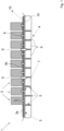
- Figure 1 shows a cross section of part of a battery pack according to an embodiment of the present invention.
- FIG. 1 a lower part of a battery pack 1 is shown.
- the battery pack 1 comprises a plurality of battery cells 2 located on a thin layer of fragile, heat resistant material 10.
- the layer 10 is provided on top of a horizontal component in form of a horizontal plate 3.
- the horizontal plate 3 comprises a plurality of predetermined breaking points 7 each being associated with an emergency or venting opening 8 of a battery cell.
- a plurality of spacer elements 5 is provided, wherein the spacer elements 5 are arranged perpendicular to the plane of the horizontal plate 3 and are extending to a through-shaped bottom of an enclosure 4, such that also the spacer elements 5 are arranged perpendicular to a surface of the bottom of the enclosure 4.
- the spacer elements 5 are arranged on the through-shaped bottom of the enclosure 4 spacing apart said bottom from said horizontal plate 3.
- the horizontal plate 3 may act as closure for the space between the horizontal plate 3 and the through-shaped bottom.
- the spacer elements 5 provide one or more hot stream channels 6 for guiding hot stream upon entering the respective channel to an outlet.
- the horizontal plate 3 comprises a plurality of parts 3a, 3b, 3c, which are detachably connectable with each other via connections 9.
- These connections 9 may be screw connections or clip connections. Of course, other types of connections are possible.
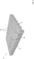
- Figure 2 shows a three-dimensional view of a grid structure of a battery pack according to an embodiment of the present invention
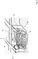
- Figure 3 shows a three-dimensional view of a compartment of a grid structure of a battery pack according to an embodiment of the present invention
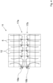
- Figure 4 shows a schematically view of output channels, preferably hot stream channels, of a battery pack according to an embodiment of the present invention.
- Figure 2 shows a plurality of spacer elements 5 arranged in a regular manner to form a grid structure 11.
- This grid structure 11 of spacer elements 5 is located between the enclosure 4 and the horizontal plate 3 supporting the horizontal plate 3.
- the grid structure 11 provides a plurality of compartments 12, which have rectangular or quadratic cross-sections. These compartments 12 can be fluidly connected with each other, at least in part, forming greater compartments 16.
- Each compartment 16 may be filed with a foam 14, e.g. a polyurethane foam, for energy and shock absorption.
- a membrane 15 can be provided in each compartment 12 providing a volume to be filled with the foam 14 as well as to increase energy absorption, in particular in connection with the foam 14.
- the grid structure 11 can be of any regular or non-regular form, for instance having quadratic, rectangular, or any n-corner shaped structure, for instance hexagonal or octagonal shape.
- Each compartment 12 may comprise one or more connection channels 13 to one or more adjacent compartments 12.
- Each greater compartment 16 may also comprise one or more connection channels to other compartments 12 and/or greater compartments 16.
- the connections between the compartments 12 and/or greater compartments 16 can be provided such that hot stream channels are provided guiding them from the different compartments 12 and/or different greater compartments 16 to an at least in part common output channel of different compartments 12 and/or of different greater compartments 16 and further to one or more outlets of the battery pack 1.
- Such an arrangement, where the arrows show the flow direction of possible hot stream via connection channels 13 between the compartments 12, is shown in Figure 4 , where the openings between different compartments 12 leading to two parallel output channels 17a, 17b, each leading via further different compartments 12 to two different outlets 18a, 18b.
- connection channels 13 can be provided for instance in form of a spiral via different connected compartments 12 or the like.
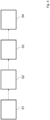
- Figure 5 shows steps of a method according to an embodiment of the present invention.
- the horizontal component 3 can be an injection molded reinforced plastic component, which can be installed underneath Li-Ion cells 2, e.g. cylindrical or prismatic, with an emergency venting opening 8 on the bottom of each cell 2.
- the horizontal component 3 can be made of one or more modules 3a, 3b, 3c, detachably joint together in order to cover the full surface of the battery pack 1.
- Each module 3a, 3b, 3c of the horizontal component 3 can be made of a horizontal plate with a system of vertical walls acting as spacer elements 5.
- Spacer elements 5 and the horizontal component 3 can be made of the same material, e.g. reinforced plastic, and formed in one piece.
- the horizontal component 3 is oriented in such a way that the cells 2 are directly sit on the horizontal plate 3, while the vertical walls, i.e. the spacer elements 5, are directly in contact with the enclosure 4 of the battery pack 1, creating hot stream channels 6.
- the horizontal plate 3 is provided with weak points/cut-outs 7 in correspondence of the venting opening 8 of each cell in form of circles, crosses or any suitable form.
- a layer 10 of fragile heat resistant material e.g. provided by overmolding or clipping, is provided on top of the horizontal component 3.
- the released hot stream breaks locally the fragile material of the layer 10 and the plastic plate in correspondence of the weak point/cut-out 7 and flows to the pack outlet through the channels 6, which can be created between the vertical walls, i.e the spacer elements 5 and a bottom of the enclosure 4 in form of a metal tray.
- the fragile material of the layer 10 and weak point/cut-out 7 are provided, e.g. placed and/or installed in correspondence of the life cells 2, protecting the cells 2 from the heat of a hot stream.
- a grid structure 11 is placed under the battery cells 2.
- the cells 2 are placed over a plate 3, which is also integrating an element 7, which opens when the cell 2 is venting in order to orient the gas flow.
- the grid structure 11 may be light-weight and it could enhance stiffness to the battery pack 1.
- the grid structure 11 can be produced by injection moulding in a single step.
- a single element of the venting i.e. a compartment 12, may have the following features:
- the invention relates to and/or provides a battery pack comprising a plurality of battery cells, and an enclosure, wherein the plurality of battery cells are arranged on top of a horizontal component, preferably in form of a plate and that the horizontal component is spaced apart from the enclosure by at least one spacer element, said at least one spacer element providing at least one hot stream channel for evacuating hot gases during thermal runaway.
- said spacer element can act as mechanical energy dissipator/absorber in case of crush with external impactor.
- At least one embodiment may provide at least one of the following features and/or at least one of the following advantages:
Landscapes
- Chemical & Material Sciences (AREA)
- Chemical Kinetics & Catalysis (AREA)
- Electrochemistry (AREA)
- General Chemical & Material Sciences (AREA)
- Engineering & Computer Science (AREA)
- Aviation & Aerospace Engineering (AREA)
- Battery Mounting, Suspending (AREA)
- Secondary Cells (AREA)
Abstract
Description
- The present invention relates to a battery pack comprising a plurality of battery cells and an enclosure.
- The present invention further relates to a method for providing a battery pack, comprising the steps of
- Providing a plurality of battery cells, and
- Providing an enclosure.
- Although applicable to any kind of battery pack, the present invention will be described with regard to battery packs for vehicles in form of cars.
- Battery packs or batteries for automotive applications, are for instance disclosed in
US 9,698,394 B2 - One of the disadvantages is however, that a in case of a degasification event one or more of the predetermined breaking points break and cause an uncontrollable flow of the gas through said one or more breaking points into the surroundings of the battery, heating and damaging the neighboring cells. A further disadvantage is that in case of impact event, e.g. crush with an impactor at the bottom of the battery pack, the impact energy will be provided to the adjacent cells causing potential damage to them.
- An objective of the present invention is therefore to provide a battery pack and a method for providing a battery pack enabling a battery pack providing enhanced shock or impact absorption at least in part as well as a guiding of the gas of degasification events of one or more of the battery cells of the battery pack.
- In an embodiment, the present invention solves the above-mentioned objectives with a battery pack comprising
- a plurality of battery cells, and
- an enclosure,
- characterized in that
- the plurality of battery cells are arranged on top of a horizontal component, preferably in form of a plate, and that
- the horizontal component is spaced apart from the enclosure by at least one spacer element, said at least one spacer element providing at least one hot stream channel.
- In an embodiment, the present invention solves the above-mentioned objectives by a method for providing a battery pack, comprising the steps of
- Providing a plurality of battery cells,
- Providing an enclosure,
- Arranging the plurality of battery cells on top of a horizontal component,
- Spacing apart the horizontal component from the enclosure by at least one spacer element, wherein said at least one spacer element provides at least one hot stream channel,
- One of the advantages that may be achieved is that the shock and impact absorption is enhanced, in particular due to the spacer elements acting as a mechanical and/or impact energy dissipator in case of impact/crush with an impactor. A further advantage may be that a guided venting of degasification events is provided, e.g. released during thermal runaway events. A further advantage may be that the overall stiffness of the battery pack is enhanced, in particular due to the spacer elements acting as a mechanical reinforcement elements.
- The term "hot stream channel" is to be understood in its broadest sense and applies to any kind of channel, guiding, duct, pipe or the like for guiding, directing or the like of fluid streams of any kind of temperature between 0 °C and 1.500 °C for instance, wherein a fluid comprising one or more liquids and/or one or more gases.
- Further features, advantages and preferred embodiments are disclosed or may become apparent in the following.
- According to a preferred embodiment, the horizontal component comprises at least one predetermined breaking point formed such to provide a hot stream flow to enter said at least one hot stream channel upon breaking said at least one breaking point, preferably each with one hot stream channel. This may provide a reliable way to allow a hot stream to enter the hot stream channel in case of a venting event of the battery pack.
- According to a further preferred embodiment, each predetermined breaking point is provided such that upon breaking of an emergency opening of a battery cell, hot stream flows to said breaking point. This may further enhance the reliability of the guiding providing a short distance to the hot stream channel and avoiding potential damage to surrounding battery cells. The term "emergency opening" is to be understood in its broadest sense and means in particular in the claims, preferably in the description any dedicated opening, which is closed during normal operation and/or which can be opened, from the cell side to the enclosure side but not vice versa and is opened in case of an internal or external event causing an abnormal operation.
- According to a further preferred embodiment, said at least one breaking point is provided in form of a local thickness and/or density reduction and/or a fragile element, preferably a membrane, within the horizontal component. This may enable an easy and cost-effective while reliable way to provide a breaking point.
- According to a further preferred embodiment, the horizontal component comprises at least two parts detachably joined together, preferably via one or more screw connections and/or one or more clip connections. This may enable an easy manufacturing as well as an easier handling after lifetime of the battery pack for recycling purposes of the horizontal component.
- According to a further preferred embodiment, between the horizontal component and at least one of the battery cells a layer component is arranged comprising heat resistant material, preferably fragile heat resistant material. The layer component may be provided by overmoulding or clipping. An advantage may be that hot stream from a battery cell breaks the fragile material only locally, in correspondence to location of the predetermined breaking point. In this way the probability of damaging the battery cells and the horizontal component away from the breaking point is reduced or even damage can be avoided. Of course, there may be a plurality of layer components arranged.
- According to a further preferred embodiment, at least two spacer elements are provided, wherein the spacer elements are spaced apart from each other providing a hot stream channel between said two spacer elements. This may even further enhance the stiffness of the battery pack as well as provides an easy way for guiding a hot stream. A complicated single spacer element providing a hot stream channel as a via or channel within said spacer element can be avoided.
- According to a further preferred embodiment, the spacer elements are arranged essentially perpendicular to the horizontal component. This may allow an easy installation, an increased stiffness as well as a good protection of the battery cells on top of the horizontal component against impacts.
- According to a further preferred embodiment, the enclosure comprises at least in part a metal and/or plastic, preferably a thermoplastic. This may allow an easy, cost-effective and flexible manufacture of the enclosure. For instance, part of the enclosure comprising metal allow a cooling down of the hot stream before reaching a battery pack outlet.
- According to a further preferred embodiment, a bottom of the enclosure is connected to the horizontal component via said at least one spacer element. This may allow an easy way to provide one or more hot stream channels. Further, the probability of the hot stream to damage other battery cells is reduced.
- According to a further preferred embodiment, said at least one hot stream channel comprises one or more sections having at least in part a spiral, serpentine, or labyrinth form, preferably wherein said at least one hot stream channel is provided in form of a spiral, serpentine, or labyrinth. This may further enable a further cooling down of a hot stream before reaching an outlet of the battery pack and trap as well released hot particles.
- According to a further preferred embodiment, a bottom of the enclosure is trough-shaped providing a receptacle for hot stream. This may enable a cooling down of the hot stream without affecting or damaging other battery cells while providing in an easy way a receptacle for hot streams.
- According to a further preferred embodiment, a plurality of spacer elements is formed such to provide a grid structure, preferably forming a plurality of separate compartments. This may enhance the stiffness of the battery pack as well as the energy absorption when an impact intrusion occurs. If separate compartments are provided, flexibility is enhanced allowing separating the hot stream of a damaged battery cell from hot streams of other damaged battery cells.
- According to a further preferred embodiment, at least two of said plurality of compartments are connected via a inter compartment channel, preferably wherein two adjacent compartments are connected via an opening in the common wall of said two compartments. This may enable a guiding of one or more hot streams in an easy while reliable way to an outlet of the battery pack.
- According to a further preferred embodiment, a shock absorbing element, preferably foam, preferably PUR foam, is provided in at least one of the compartments, preferably in each compartment. This may enable a further enhancement in the shock absorbing properties of the battery pack. "PUR" means here polyurethane.
- According to a further preferred embodiment, the shock absorbing element is covered with a membrane element, preferably wherein the shock absorbing element is located below an inter compartment channel. This may allow a further enhancement of the reliability of the operation of the battery pack. The additional membrane inside a compartment and below the inter compartment channel, e.g. an opening in a wall between two compartments, to avoid a blocking of the opening by the shock absorbing element and/or the membrane allows for a further damping of the shock absorbing element upon impact.
- According to a further preferred embodiment, the horizontal component is made of plastic, preferably reinforced plastic. This provides an easy to produce and cost-effective, light-weight horizontal component.
- There are several ways how to design and further develop the teaching of the present invention in an advantageous way. To this end, it is to be referred to the patent claims subordinate to the independent claims on the one hand and to the following explanation of further embodiments of the invention by way of example, illustrated by the figures on the other hand. In connection with the explanation of the further embodiments of the invention by the aid of the figures, generally further embodiments and further developments of the teaching will be explained.
- In the drawings
- Fig. 1
- shows a cross section of part of a battery pack according to an embodiment of the present invention;
- Fig. 2
- shows a three-dimensional view of a grid structure of a battery pack according to an embodiment of the present invention;
- Fig. 3
- shows a three-dimensional view of a compartment of a grid structure of a battery pack according to an embodiment of the present invention;
- Fig. 4
- shows a schematically view of output channels, preferably hot stream channels, of a battery pack according to an embodiment of the present invention; and
- Fig. 5
- shows steps of a method according to an embodiment of the present invention.
-
Figure 1 shows a cross section of part of a battery pack according to an embodiment of the present invention. - In
Figure 1 , a lower part of a battery pack 1 is shown. The battery pack 1 comprises a plurality ofbattery cells 2 located on a thin layer of fragile, heatresistant material 10. Thelayer 10 is provided on top of a horizontal component in form of ahorizontal plate 3. Thehorizontal plate 3 comprises a plurality ofpredetermined breaking points 7 each being associated with an emergency or ventingopening 8 of a battery cell. - Beneath the
horizontal plate 3 a plurality ofspacer elements 5 is provided, wherein thespacer elements 5 are arranged perpendicular to the plane of thehorizontal plate 3 and are extending to a through-shaped bottom of anenclosure 4, such that also thespacer elements 5 are arranged perpendicular to a surface of the bottom of theenclosure 4. In other words, thespacer elements 5 are arranged on the through-shaped bottom of theenclosure 4 spacing apart said bottom from saidhorizontal plate 3. Thehorizontal plate 3 may act as closure for the space between thehorizontal plate 3 and the through-shaped bottom. Thespacer elements 5 provide one or morehot stream channels 6 for guiding hot stream upon entering the respective channel to an outlet. - The
horizontal plate 3 comprises a plurality ofparts connections 9. Theseconnections 9 may be screw connections or clip connections. Of course, other types of connections are possible. -
Figure 2 shows a three-dimensional view of a grid structure of a battery pack according to an embodiment of the present invention,Figure 3 shows a three-dimensional view of a compartment of a grid structure of a battery pack according to an embodiment of the present invention andFigure 4 shows a schematically view of output channels, preferably hot stream channels, of a battery pack according to an embodiment of the present invention. - In Detail,
Figure 2 shows a plurality ofspacer elements 5 arranged in a regular manner to form agrid structure 11. Thisgrid structure 11 ofspacer elements 5 is located between theenclosure 4 and thehorizontal plate 3 supporting thehorizontal plate 3. Thegrid structure 11 provides a plurality ofcompartments 12, which have rectangular or quadratic cross-sections. Thesecompartments 12 can be fluidly connected with each other, at least in part, forminggreater compartments 16. Eachcompartment 16 may be filed with afoam 14, e.g. a polyurethane foam, for energy and shock absorption. Further, amembrane 15 can be provided in eachcompartment 12 providing a volume to be filled with thefoam 14 as well as to increase energy absorption, in particular in connection with thefoam 14. - The
grid structure 11 can be of any regular or non-regular form, for instance having quadratic, rectangular, or any n-corner shaped structure, for instance hexagonal or octagonal shape. - Each
compartment 12 may comprise one ormore connection channels 13 to one or moreadjacent compartments 12. Eachgreater compartment 16 may also comprise one or more connection channels toother compartments 12 and/or greater compartments 16. The connections between thecompartments 12 and/orgreater compartments 16 can be provided such that hot stream channels are provided guiding them from thedifferent compartments 12 and/or differentgreater compartments 16 to an at least in part common output channel ofdifferent compartments 12 and/or of differentgreater compartments 16 and further to one or more outlets of the battery pack 1. Such an arrangement, where the arrows show the flow direction of possible hot stream viaconnection channels 13 between thecompartments 12, is shown inFigure 4 , where the openings betweendifferent compartments 12 leading to twoparallel output channels different compartments 12 to twodifferent outlets - The
connection channels 13 can be provided for instance in form of a spiral via differentconnected compartments 12 or the like. -
Figure 5 shows steps of a method according to an embodiment of the present invention. - In
Figure 5 steps of a method for providing a battery pack is shown. The method comprises the steps of - Providing S1 a plurality of
battery cells 2, - Providing S2 an
enclosure 4, - Arranging S3 the plurality of
battery cells 2 on top of ahorizontal component 3, - Spacing apart S4 the
horizontal component 3 from theenclosure 4 by at least onespacer element 5, wherein said at least onespacer element 5 provides at least one hot stream channel, - In an embodiment, e.g. shown in
Figure 1 , thehorizontal component 3 can be an injection molded reinforced plastic component, which can be installed underneath Li-Ion cells 2, e.g. cylindrical or prismatic, with anemergency venting opening 8 on the bottom of eachcell 2. - In a further embodiment, the
horizontal component 3 can be made of one ormore modules module horizontal component 3 can be made of a horizontal plate with a system of vertical walls acting asspacer elements 5.Spacer elements 5 and thehorizontal component 3 can be made of the same material, e.g. reinforced plastic, and formed in one piece. Thehorizontal component 3 is oriented in such a way that thecells 2 are directly sit on thehorizontal plate 3, while the vertical walls, i.e. thespacer elements 5, are directly in contact with theenclosure 4 of the battery pack 1, creatinghot stream channels 6. Thehorizontal plate 3 is provided with weak points/cut-outs 7 in correspondence of theventing opening 8 of each cell in form of circles, crosses or any suitable form. On top of thehorizontal component 3, alayer 10 of fragile heat resistant material, e.g. provided by overmolding or clipping, is provided. When acell 2 goes in thermal runaway, the released hot stream breaks locally the fragile material of thelayer 10 and the plastic plate in correspondence of the weak point/cut-out 7 and flows to the pack outlet through thechannels 6, which can be created between the vertical walls, i.e thespacer elements 5 and a bottom of theenclosure 4 in form of a metal tray. The fragile material of thelayer 10 and weak point/cut-out 7 are provided, e.g. placed and/or installed in correspondence of thelife cells 2, protecting thecells 2 from the heat of a hot stream. - In another embodiment, as shown for instance in
Figure 2 , agrid structure 11 is placed under thebattery cells 2. Thecells 2 are placed over aplate 3, which is also integrating anelement 7, which opens when thecell 2 is venting in order to orient the gas flow. Thegrid structure 11 may be light-weight and it could enhance stiffness to the battery pack 1. Thegrid structure 11 can be produced by injection moulding in a single step. - A single element of the venting, i.e. a
compartment 12, may have the following features: - Holes or
openings 13 in the sidewalls of thespacer elements 5 allow to manage the flow of the venting. Different positions of the holes allow to manage the direction as required formingoutput channels - One or more of the holes or
openings 13 can be designed to create also energy absorption as collapsible structure. - The
compartment 12 may have amembrane 15, which can be produced during the injection moulding of thegrid structure 11. It may provides giving a volume to fill with a PUR foam and/or making energy adsorption by using tailored design. The PUR foam is light and it allows to absorb energy during impact, e.g. a crush, or an intrusion. The plastic PUR can be added with a secondary process or with a thermoplastic/thermosetting combined machine. The type of the PUR foam could be designed to improve the energy absorption and is adapted to the dimension of the compartment or greater compartment, etc.. Other materials can be used, e.g. thermosetting, like EPDM foam, etc., and/or thermoplastic, e.g. TPE bulk in 2K process, foamed PE/PP or PVC or the like, wherein TPE means thermoplastic elastomer, PE means polyethylene, PP means polypropylene, EPDM means ethylene propylene diene monomer rubber and PVC means polyvinyl chloride. Thegrid structure 11 could have optimized wall thickness, orientation and relative dimensions of thespacer elements 5 and/or their position toother spacer elements 5. - In an embodiment the invention relates to and/or provides a battery pack comprising a plurality of battery cells, and an enclosure, wherein the plurality of battery cells are arranged on top of a horizontal component, preferably in form of a plate and that the horizontal component is spaced apart from the enclosure by at least one spacer element, said at least one spacer element providing at least one hot stream channel for evacuating hot gases during thermal runaway. In addition said spacer element can act as mechanical energy dissipator/absorber in case of crush with external impactor.
- At least one embodiment may provide at least one of the following features and/or at least one of the following advantages:
- Providing structure to the battery pack.
- Enhancing impact stiffness to the battery pack.
- Light-weight.
- Protecting the cells from impact intrusion, e.g. by using openings collapsible and/or foam and/or membranes.
- Providing, e.g. in case of thermal runaway, a safe guidance of the hot venting stream to an outlet, venting management.
- Easy and cost-effective manufacture of the battery pack.
- Providing at least one hot stream channel for evacuating hot gases during thermal runaway by at least one spacer element.
- Said at least one spacer element can act as mechanical energy dissipator/absorber in case of crush with external impactor.
- Many modifications and other embodiments of the invention set forth herein will come to mind to the one skilled in the art to which the invention pertains having the benefit of the teachings presented in the foregoing description and the associated drawings. Therefore, it is to be understood that the invention is not to be limited to the specific embodiments disclosed and that modifications and other embodiments are intended to be included within the scope of the appended claims. Although specific terms are employed herein, they are used in a generic and descriptive sense only and not for purposes of limitation.
-
- 1
- Battery pack
- 2
- Battery cell
- 3
- Horizontal component
- 3a, 3b, 3c
- Module of horizontal component
- 4
- Enclosure
- 5
- Spacer element
- 6
- Channel
- 7
- Breaking point/weak point
- 8
- Emergency opening
- 9
- Connection
- 10
- Layer component
- 11
- Grid of spacer elements
- 12
- Compartment
- 13
- Opening
- 14
- PUR foam
- 15
- Membrane
- 16
- Connected/greater compartments
- 17a, 17b
- Output channel
- 18a, 18b
- Outlet
- S1-S4
- Method steps
Claims (15)
- Battery pack (1) comprisinga plurality of battery cells (2), andan enclosure (4),characterized in thatthe plurality of battery cells (2) are arranged on top of a horizontal component (3), preferably in form of a plate and thatthe horizontal component (3) is spaced apart from the enclosure(4) by at least one spacer element (5), said at least one spacer element (5) providing at least one hot stream channel (6).
- Battery pack (1) according to claim 1, characterized in that the horizontal component (3) comprises at least one predetermined breaking point (7) formed such to provide a hot stream flow to enter said at least one hot stream channel (6) upon breaking said at least one breaking point (7), preferably each with one hot stream channel (6) and/or wherein the horizontal component (3) is made of plastic, preferably reinforced plastic.
- Battery pack (1) according to claim 2, characterized in that each predetermined breaking point (7) is provided such that upon breaking of an emergency opening (8) of a battery cell (2), hot stream flows to said breaking point (7).
- Battery pack (1) according to one of the claims 2 or 3, characterized in that said at least one breaking point (7) is provided in form of a local thickness and/or density reduction and/or a fragile element (15), preferably a membrane, within the horizontal component (3).
- Battery pack (1) according to one of the claims 1-4, characterized in that the horizontal component (3) comprises at least two parts (3a, 3b, 3c) detachably joined together, preferably via one or more screw connections (9) and/or one or more clip connections.
- Battery pack (1) according to one of the claims 1-5, characterized in that between the horizontal component (3) and at least one of the battery cells (2), a layer component (10) is arranged comprising heat resistant material, preferably fragile heat resistant material.
- Battery pack (1) according to one of the claims 1-6, characterized in that at least two spacer elements (5) are provided, wherein the spacer elements (5) are spaced apart from each other providing a hot stream channel (6) between said two spacer elements (5), preferably wherein a plurality of spacer elements (5) is formed such to provide a grid structure (11), preferably forming a plurality of separate compartments (12).
- Battery pack (1) according to claim 7, characterized in that the spacer elements (5) are arranged essentially perpendicular to the horizontal component (3).
- Battery pack (1) according to one of the claims 1-8, characterized in that the enclosure (4) comprises at least in part a metal and/or plastic, preferably a thermoplastic and/or wherein a bottom of the enclosure (4) is connected to the horizontal component (3) via said at least one spacer element (5).
- Battery pack (1) according to one of the claims 1-9, characterized in that said at least one hot stream channel (6) comprises one or more sections having at least in part a spiral, serpentine, or labyrinth form, preferably wherein said at least one hot stream channel (6) is provided in form of a spiral, serpentine, or labyrinth.
- Battery pack (1) according to one of the claims 1-10, characterized in that a bottom of the enclosure (4) is trough-shaped providing a receptacle for a hot stream.
- Battery pack (1) according to claim 7, characterized in that at least two of said plurality of compartments (12) are connected via an inter compartment channel (13), preferably wherein two adjacent compartments (12) are connected via an opening (13) in the common wall of said two compartments (12).
- Battery pack (1) according to at least claim 7, characterized in that a shock absorbing element (14), preferably foam, preferably PUR foam, is provided in at least one of the compartments (12), preferably in each compartment (12).
- Battery pack (1) according to claim 13, characterized in that the shock absorbing element (14) is covered with a membrane element (15), preferably wherein the shock absorbing element (14) is located below an inter compartment channel (13).
- Method for providing a battery pack (1), comprising the steps of- Providing (S1) a plurality of battery cells (2),- Providing (S2) an enclosure (4),- Arranging (S3) the plurality of battery cells (2) on top of a horizontal component (3),- Spacing (S4) apart the horizontal component (3) from the enclosure (4) by at least one spacer element (5), wherein said at least one spacer element (5) provides at least one hot stream channel (6),preferably wherein said horizontal component (3) is manufactured using injection moulding.
Priority Applications (2)
| Application Number | Priority Date | Filing Date | Title |
|---|---|---|---|
| EP23174879.9A EP4468451B1 (en) | 2023-05-23 | 2023-05-23 | Battery pack |
| CN202410638485.0A CN119029444A (en) | 2023-05-23 | 2024-05-22 | Battery Pack |
Applications Claiming Priority (1)
| Application Number | Priority Date | Filing Date | Title |
|---|---|---|---|
| EP23174879.9A EP4468451B1 (en) | 2023-05-23 | 2023-05-23 | Battery pack |
Publications (2)
| Publication Number | Publication Date |
|---|---|
| EP4468451A1 true EP4468451A1 (en) | 2024-11-27 |
| EP4468451B1 EP4468451B1 (en) | 2025-07-23 |
Family
ID=86497984
Family Applications (1)
| Application Number | Title | Priority Date | Filing Date |
|---|---|---|---|
| EP23174879.9A Active EP4468451B1 (en) | 2023-05-23 | 2023-05-23 | Battery pack |
Country Status (2)
| Country | Link |
|---|---|
| EP (1) | EP4468451B1 (en) |
| CN (1) | CN119029444A (en) |
Citations (6)
| Publication number | Priority date | Publication date | Assignee | Title |
|---|---|---|---|---|
| US20150135939A1 (en) * | 2013-11-19 | 2015-05-21 | Atieva, Inc. | Electric Vehicle Undercarriage Crumple Zone |
| US9698394B2 (en) | 2013-05-03 | 2017-07-04 | Robert Bosch Gmbh | Battery having a cover that has predetermined breaking points |
| US10680296B2 (en) * | 2015-05-15 | 2020-06-09 | Mahle International Gmbh | Energy store of a motor vehicle |
| US11024901B2 (en) * | 2018-01-19 | 2021-06-01 | Hanon Systems | Battery cooling plate with integrated air vents |
| WO2021105328A1 (en) * | 2019-11-29 | 2021-06-03 | Kirchhoff Automotive Deutschland Gmbh | Battery housing for a vehicle driven by an electric motor |
| CN115621603A (en) * | 2021-07-16 | 2023-01-17 | 沃尔沃汽车公司 | Structural battery for electric vehicle comprising a battery cell support matrix for the battery |
-
2023
- 2023-05-23 EP EP23174879.9A patent/EP4468451B1/en active Active
-
2024
- 2024-05-22 CN CN202410638485.0A patent/CN119029444A/en active Pending
Patent Citations (6)
| Publication number | Priority date | Publication date | Assignee | Title |
|---|---|---|---|---|
| US9698394B2 (en) | 2013-05-03 | 2017-07-04 | Robert Bosch Gmbh | Battery having a cover that has predetermined breaking points |
| US20150135939A1 (en) * | 2013-11-19 | 2015-05-21 | Atieva, Inc. | Electric Vehicle Undercarriage Crumple Zone |
| US10680296B2 (en) * | 2015-05-15 | 2020-06-09 | Mahle International Gmbh | Energy store of a motor vehicle |
| US11024901B2 (en) * | 2018-01-19 | 2021-06-01 | Hanon Systems | Battery cooling plate with integrated air vents |
| WO2021105328A1 (en) * | 2019-11-29 | 2021-06-03 | Kirchhoff Automotive Deutschland Gmbh | Battery housing for a vehicle driven by an electric motor |
| CN115621603A (en) * | 2021-07-16 | 2023-01-17 | 沃尔沃汽车公司 | Structural battery for electric vehicle comprising a battery cell support matrix for the battery |
Also Published As
| Publication number | Publication date |
|---|---|
| CN119029444A (en) | 2024-11-26 |
| EP4468451B1 (en) | 2025-07-23 |
Similar Documents
| Publication | Publication Date | Title |
|---|---|---|
| US11450907B2 (en) | Battery and vehicle equipped with said battery | |
| US20210359374A1 (en) | Battery system and vehicle including the battery system | |
| CN112331997B (en) | Battery packs and vehicles | |
| US11296381B2 (en) | High-density battery pack | |
| EP3836296B1 (en) | Battery module having structure capable of preventing inflow of air into module when thermal runaway occurs and battery pack including same | |
| JP7208145B2 (en) | power supply | |
| CN114824611B (en) | Composite battery casing | |
| CN107534107B (en) | Battery pack and method for manufacturing same | |
| EP3910699A1 (en) | Battery system and vehicle including the battery system | |
| CN110190211A (en) | Battery tray, power battery pack and vehicle | |
| CN106233495B (en) | Battery module | |
| CN102714289A (en) | Battery pack | |
| KR102802530B1 (en) | Battery pack and device including the same | |
| US11824222B2 (en) | High-voltage battery for an electrically operated vehicle | |
| KR102926488B1 (en) | Battery pack with gas venting path | |
| JP6344293B2 (en) | Battery pack | |
| US20250346105A1 (en) | Underbody Protection Device, Housing Lower Part, Vehicle Floor Device, and Motor Vehicle | |
| EP4468451A1 (en) | Battery pack | |
| US20230246288A1 (en) | Pressure release vent for battery module | |
| KR20170095144A (en) | Cartridge For Secondary Battery and Secondary Battery Pack including the same | |
| KR102866245B1 (en) | A battery pack | |
| EP4166428B1 (en) | Electric vehicle underbody having water tank | |
| EP4521516A1 (en) | Battery cell fixture with cooling and degassing areas | |
| US20250202033A1 (en) | Base plate for battery system | |
| KR102950512B1 (en) | Battery pack with double cover |
Legal Events
| Date | Code | Title | Description |
|---|---|---|---|
| STAA | Information on the status of an ep patent application or granted ep patent |
Free format text: STATUS: EXAMINATION IS IN PROGRESS |
|
| PUAI | Public reference made under article 153(3) epc to a published international application that has entered the european phase |
Free format text: ORIGINAL CODE: 0009012 |
|
| 17P | Request for examination filed |
Effective date: 20230523 |
|
| AK | Designated contracting states |
Kind code of ref document: A1 Designated state(s): AL AT BE BG CH CY CZ DE DK EE ES FI FR GB GR HR HU IE IS IT LI LT LU LV MC ME MK MT NL NO PL PT RO RS SE SI SK SM TR |
|
| GRAP | Despatch of communication of intention to grant a patent |
Free format text: ORIGINAL CODE: EPIDOSNIGR1 |
|
| STAA | Information on the status of an ep patent application or granted ep patent |
Free format text: STATUS: GRANT OF PATENT IS INTENDED |
|
| RIC1 | Information provided on ipc code assigned before grant |
Ipc: H01M 50/35 20210101ALI20250107BHEP Ipc: H01M 50/249 20210101ALI20250107BHEP Ipc: H01M 50/204 20210101ALI20250107BHEP Ipc: H01M 50/242 20210101ALI20250107BHEP Ipc: H01M 50/289 20210101ALI20250107BHEP Ipc: H01M 50/30 20210101ALI20250107BHEP Ipc: H01M 10/60 20140101AFI20250107BHEP |
|
| INTG | Intention to grant announced |
Effective date: 20250128 |
|
| P01 | Opt-out of the competence of the unified patent court (upc) registered |
Free format text: CASE NUMBER: APP_12169/2025 Effective date: 20250312 |
|
| GRAS | Grant fee paid |
Free format text: ORIGINAL CODE: EPIDOSNIGR3 |
|
| GRAA | (expected) grant |
Free format text: ORIGINAL CODE: 0009210 |
|
| STAA | Information on the status of an ep patent application or granted ep patent |
Free format text: STATUS: THE PATENT HAS BEEN GRANTED |
|
| AK | Designated contracting states |
Kind code of ref document: B1 Designated state(s): AL AT BE BG CH CY CZ DE DK EE ES FI FR GB GR HR HU IE IS IT LI LT LU LV MC ME MK MT NL NO PL PT RO RS SE SI SK SM TR |
|
| REG | Reference to a national code |
Ref country code: GB Ref legal event code: FG4D |
|
| REG | Reference to a national code |
Ref country code: CH Ref legal event code: EP |
|
| REG | Reference to a national code |
Ref country code: DE Ref legal event code: R096 Ref document number: 602023004959 Country of ref document: DE |
|
| REG | Reference to a national code |
Ref country code: IE Ref legal event code: FG4D |
|
| REG | Reference to a national code |
Ref country code: NL Ref legal event code: MP Effective date: 20250723 |
|
| PG25 | Lapsed in a contracting state [announced via postgrant information from national office to epo] |
Ref country code: PT Free format text: LAPSE BECAUSE OF FAILURE TO SUBMIT A TRANSLATION OF THE DESCRIPTION OR TO PAY THE FEE WITHIN THE PRESCRIBED TIME-LIMIT Effective date: 20251124 |
|
| PG25 | Lapsed in a contracting state [announced via postgrant information from national office to epo] |
Ref country code: NL Free format text: LAPSE BECAUSE OF FAILURE TO SUBMIT A TRANSLATION OF THE DESCRIPTION OR TO PAY THE FEE WITHIN THE PRESCRIBED TIME-LIMIT Effective date: 20250723 |
|
| REG | Reference to a national code |
Ref country code: AT Ref legal event code: MK05 Ref document number: 1817399 Country of ref document: AT Kind code of ref document: T Effective date: 20250723 |
|
| PG25 | Lapsed in a contracting state [announced via postgrant information from national office to epo] |
Ref country code: IS Free format text: LAPSE BECAUSE OF FAILURE TO SUBMIT A TRANSLATION OF THE DESCRIPTION OR TO PAY THE FEE WITHIN THE PRESCRIBED TIME-LIMIT Effective date: 20251123 |
|
| PG25 | Lapsed in a contracting state [announced via postgrant information from national office to epo] |
Ref country code: NO Free format text: LAPSE BECAUSE OF FAILURE TO SUBMIT A TRANSLATION OF THE DESCRIPTION OR TO PAY THE FEE WITHIN THE PRESCRIBED TIME-LIMIT Effective date: 20251023 |
|
| REG | Reference to a national code |
Ref country code: LT Ref legal event code: MG9D |
|
| PG25 | Lapsed in a contracting state [announced via postgrant information from national office to epo] |
Ref country code: AT Free format text: LAPSE BECAUSE OF FAILURE TO SUBMIT A TRANSLATION OF THE DESCRIPTION OR TO PAY THE FEE WITHIN THE PRESCRIBED TIME-LIMIT Effective date: 20250723 |
|
| PG25 | Lapsed in a contracting state [announced via postgrant information from national office to epo] |
Ref country code: FI Free format text: LAPSE BECAUSE OF FAILURE TO SUBMIT A TRANSLATION OF THE DESCRIPTION OR TO PAY THE FEE WITHIN THE PRESCRIBED TIME-LIMIT Effective date: 20250723 |
|
| PG25 | Lapsed in a contracting state [announced via postgrant information from national office to epo] |
Ref country code: HR Free format text: LAPSE BECAUSE OF FAILURE TO SUBMIT A TRANSLATION OF THE DESCRIPTION OR TO PAY THE FEE WITHIN THE PRESCRIBED TIME-LIMIT Effective date: 20250723 |
|
| PG25 | Lapsed in a contracting state [announced via postgrant information from national office to epo] |
Ref country code: GR Free format text: LAPSE BECAUSE OF FAILURE TO SUBMIT A TRANSLATION OF THE DESCRIPTION OR TO PAY THE FEE WITHIN THE PRESCRIBED TIME-LIMIT Effective date: 20251024 |
|
| PG25 | Lapsed in a contracting state [announced via postgrant information from national office to epo] |
Ref country code: SE Free format text: LAPSE BECAUSE OF FAILURE TO SUBMIT A TRANSLATION OF THE DESCRIPTION OR TO PAY THE FEE WITHIN THE PRESCRIBED TIME-LIMIT Effective date: 20250723 |
|
| PG25 | Lapsed in a contracting state [announced via postgrant information from national office to epo] |
Ref country code: LV Free format text: LAPSE BECAUSE OF FAILURE TO SUBMIT A TRANSLATION OF THE DESCRIPTION OR TO PAY THE FEE WITHIN THE PRESCRIBED TIME-LIMIT Effective date: 20250723 |
|
| PG25 | Lapsed in a contracting state [announced via postgrant information from national office to epo] |
Ref country code: BG Free format text: LAPSE BECAUSE OF FAILURE TO SUBMIT A TRANSLATION OF THE DESCRIPTION OR TO PAY THE FEE WITHIN THE PRESCRIBED TIME-LIMIT Effective date: 20250723 Ref country code: PL Free format text: LAPSE BECAUSE OF FAILURE TO SUBMIT A TRANSLATION OF THE DESCRIPTION OR TO PAY THE FEE WITHIN THE PRESCRIBED TIME-LIMIT Effective date: 20250723 |
|
| PG25 | Lapsed in a contracting state [announced via postgrant information from national office to epo] |
Ref country code: RS Free format text: LAPSE BECAUSE OF FAILURE TO SUBMIT A TRANSLATION OF THE DESCRIPTION OR TO PAY THE FEE WITHIN THE PRESCRIBED TIME-LIMIT Effective date: 20251023 |
|
| PG25 | Lapsed in a contracting state [announced via postgrant information from national office to epo] |
Ref country code: ES Free format text: LAPSE BECAUSE OF FAILURE TO SUBMIT A TRANSLATION OF THE DESCRIPTION OR TO PAY THE FEE WITHIN THE PRESCRIBED TIME-LIMIT Effective date: 20250723 |
|
| PG25 | Lapsed in a contracting state [announced via postgrant information from national office to epo] |
Ref country code: SM Free format text: LAPSE BECAUSE OF FAILURE TO SUBMIT A TRANSLATION OF THE DESCRIPTION OR TO PAY THE FEE WITHIN THE PRESCRIBED TIME-LIMIT Effective date: 20250723 |
|
| PG25 | Lapsed in a contracting state [announced via postgrant information from national office to epo] |
Ref country code: DK Free format text: LAPSE BECAUSE OF FAILURE TO SUBMIT A TRANSLATION OF THE DESCRIPTION OR TO PAY THE FEE WITHIN THE PRESCRIBED TIME-LIMIT Effective date: 20250723 |
|
| PG25 | Lapsed in a contracting state [announced via postgrant information from national office to epo] |
Ref country code: IT Free format text: LAPSE BECAUSE OF FAILURE TO SUBMIT A TRANSLATION OF THE DESCRIPTION OR TO PAY THE FEE WITHIN THE PRESCRIBED TIME-LIMIT Effective date: 20250723 |
|
| PG25 | Lapsed in a contracting state [announced via postgrant information from national office to epo] |
Ref country code: CZ Free format text: LAPSE BECAUSE OF FAILURE TO SUBMIT A TRANSLATION OF THE DESCRIPTION OR TO PAY THE FEE WITHIN THE PRESCRIBED TIME-LIMIT Effective date: 20250723 |
|
| PG25 | Lapsed in a contracting state [announced via postgrant information from national office to epo] |
Ref country code: SK Free format text: LAPSE BECAUSE OF FAILURE TO SUBMIT A TRANSLATION OF THE DESCRIPTION OR TO PAY THE FEE WITHIN THE PRESCRIBED TIME-LIMIT Effective date: 20250723 Ref country code: EE Free format text: LAPSE BECAUSE OF FAILURE TO SUBMIT A TRANSLATION OF THE DESCRIPTION OR TO PAY THE FEE WITHIN THE PRESCRIBED TIME-LIMIT Effective date: 20250723 |