EP4468443A1 - Winding-type electrode assembly, battery cell, battery, electric apparatus and winding device - Google Patents
Winding-type electrode assembly, battery cell, battery, electric apparatus and winding device Download PDFInfo
- Publication number
- EP4468443A1 EP4468443A1 EP22959945.1A EP22959945A EP4468443A1 EP 4468443 A1 EP4468443 A1 EP 4468443A1 EP 22959945 A EP22959945 A EP 22959945A EP 4468443 A1 EP4468443 A1 EP 4468443A1
- Authority
- EP
- European Patent Office
- Prior art keywords
- electrode plate
- separator
- electrode assembly
- irradiation device
- winding apparatus
- Prior art date
- Legal status (The legal status is an assumption and is not a legal conclusion. Google has not performed a legal analysis and makes no representation as to the accuracy of the status listed.)
- Pending
Links
Images


Classifications
-
- H—ELECTRICITY
- H01—ELECTRIC ELEMENTS
- H01M—PROCESSES OR MEANS, e.g. BATTERIES, FOR THE DIRECT CONVERSION OF CHEMICAL ENERGY INTO ELECTRICAL ENERGY
- H01M10/00—Secondary cells; Manufacture thereof
- H01M10/05—Accumulators with non-aqueous electrolyte
- H01M10/058—Construction or manufacture
- H01M10/0587—Construction or manufacture of accumulators having only wound construction elements, i.e. wound positive electrodes, wound negative electrodes and wound separators
-
- C—CHEMISTRY; METALLURGY
- C09—DYES; PAINTS; POLISHES; NATURAL RESINS; ADHESIVES; COMPOSITIONS NOT OTHERWISE PROVIDED FOR; APPLICATIONS OF MATERIALS NOT OTHERWISE PROVIDED FOR
- C09J—ADHESIVES; NON-MECHANICAL ASPECTS OF ADHESIVE PROCESSES IN GENERAL; ADHESIVE PROCESSES NOT PROVIDED FOR ELSEWHERE; USE OF MATERIALS AS ADHESIVES
- C09J5/00—Adhesive processes in general; Adhesive processes not provided for elsewhere, e.g. relating to primers
-
- C—CHEMISTRY; METALLURGY
- C09—DYES; PAINTS; POLISHES; NATURAL RESINS; ADHESIVES; COMPOSITIONS NOT OTHERWISE PROVIDED FOR; APPLICATIONS OF MATERIALS NOT OTHERWISE PROVIDED FOR
- C09J—ADHESIVES; NON-MECHANICAL ASPECTS OF ADHESIVE PROCESSES IN GENERAL; ADHESIVE PROCESSES NOT PROVIDED FOR ELSEWHERE; USE OF MATERIALS AS ADHESIVES
- C09J9/00—Adhesives characterised by their physical nature or the effects produced, e.g. glue sticks
-
- G—PHYSICS
- G01—MEASURING; TESTING
- G01D—MEASURING NOT SPECIALLY ADAPTED FOR A SPECIFIC VARIABLE; ARRANGEMENTS FOR MEASURING TWO OR MORE VARIABLES NOT COVERED IN A SINGLE OTHER SUBCLASS; TARIFF METERING APPARATUS; MEASURING OR TESTING NOT OTHERWISE PROVIDED FOR
- G01D21/00—Measuring or testing not otherwise provided for
- G01D21/02—Measuring two or more variables by means not covered by a single other subclass
-
- H—ELECTRICITY
- H01—ELECTRIC ELEMENTS
- H01M—PROCESSES OR MEANS, e.g. BATTERIES, FOR THE DIRECT CONVERSION OF CHEMICAL ENERGY INTO ELECTRICAL ENERGY
- H01M10/00—Secondary cells; Manufacture thereof
- H01M10/04—Construction or manufacture in general
- H01M10/0404—Machines for assembling batteries
-
- H—ELECTRICITY
- H01—ELECTRIC ELEMENTS
- H01M—PROCESSES OR MEANS, e.g. BATTERIES, FOR THE DIRECT CONVERSION OF CHEMICAL ENERGY INTO ELECTRICAL ENERGY
- H01M10/00—Secondary cells; Manufacture thereof
- H01M10/04—Construction or manufacture in general
- H01M10/0404—Machines for assembling batteries
- H01M10/0409—Machines for assembling batteries for cells with wound electrodes
-
- H—ELECTRICITY
- H01—ELECTRIC ELEMENTS
- H01M—PROCESSES OR MEANS, e.g. BATTERIES, FOR THE DIRECT CONVERSION OF CHEMICAL ENERGY INTO ELECTRICAL ENERGY
- H01M10/00—Secondary cells; Manufacture thereof
- H01M10/04—Construction or manufacture in general
- H01M10/0431—Cells with wound or folded electrodes
-
- H—ELECTRICITY
- H01—ELECTRIC ELEMENTS
- H01M—PROCESSES OR MEANS, e.g. BATTERIES, FOR THE DIRECT CONVERSION OF CHEMICAL ENERGY INTO ELECTRICAL ENERGY
- H01M10/00—Secondary cells; Manufacture thereof
- H01M10/42—Methods or arrangements for servicing or maintenance of secondary cells or secondary half-cells
- H01M10/4235—Safety or regulating additives or arrangements in electrodes, separators or electrolyte
-
- H—ELECTRICITY
- H01—ELECTRIC ELEMENTS
- H01M—PROCESSES OR MEANS, e.g. BATTERIES, FOR THE DIRECT CONVERSION OF CHEMICAL ENERGY INTO ELECTRICAL ENERGY
- H01M50/00—Constructional details or processes of manufacture of the non-active parts of electrochemical cells other than fuel cells, e.g. hybrid cells
- H01M50/40—Separators; Membranes; Diaphragms; Spacing elements inside cells
- H01M50/403—Manufacturing processes of separators, membranes or diaphragms
-
- H—ELECTRICITY
- H01—ELECTRIC ELEMENTS
- H01M—PROCESSES OR MEANS, e.g. BATTERIES, FOR THE DIRECT CONVERSION OF CHEMICAL ENERGY INTO ELECTRICAL ENERGY
- H01M50/00—Constructional details or processes of manufacture of the non-active parts of electrochemical cells other than fuel cells, e.g. hybrid cells
- H01M50/40—Separators; Membranes; Diaphragms; Spacing elements inside cells
- H01M50/409—Separators, membranes or diaphragms characterised by the material
- H01M50/411—Organic material
- H01M50/414—Synthetic resins, e.g. thermoplastics or thermosetting resins
- H01M50/417—Polyolefins
-
- H—ELECTRICITY
- H01—ELECTRIC ELEMENTS
- H01M—PROCESSES OR MEANS, e.g. BATTERIES, FOR THE DIRECT CONVERSION OF CHEMICAL ENERGY INTO ELECTRICAL ENERGY
- H01M50/00—Constructional details or processes of manufacture of the non-active parts of electrochemical cells other than fuel cells, e.g. hybrid cells
- H01M50/40—Separators; Membranes; Diaphragms; Spacing elements inside cells
- H01M50/409—Separators, membranes or diaphragms characterised by the material
- H01M50/449—Separators, membranes or diaphragms characterised by the material having a layered structure
-
- H—ELECTRICITY
- H01—ELECTRIC ELEMENTS
- H01M—PROCESSES OR MEANS, e.g. BATTERIES, FOR THE DIRECT CONVERSION OF CHEMICAL ENERGY INTO ELECTRICAL ENERGY
- H01M50/00—Constructional details or processes of manufacture of the non-active parts of electrochemical cells other than fuel cells, e.g. hybrid cells
- H01M50/40—Separators; Membranes; Diaphragms; Spacing elements inside cells
- H01M50/46—Separators, membranes or diaphragms characterised by their combination with electrodes
- H01M50/461—Separators, membranes or diaphragms characterised by their combination with electrodes with adhesive layers between electrodes and separators
-
- H—ELECTRICITY
- H01—ELECTRIC ELEMENTS
- H01M—PROCESSES OR MEANS, e.g. BATTERIES, FOR THE DIRECT CONVERSION OF CHEMICAL ENERGY INTO ELECTRICAL ENERGY
- H01M50/00—Constructional details or processes of manufacture of the non-active parts of electrochemical cells other than fuel cells, e.g. hybrid cells
- H01M50/40—Separators; Membranes; Diaphragms; Spacing elements inside cells
- H01M50/471—Spacing elements inside cells other than separators, membranes or diaphragms; Manufacturing processes thereof
- H01M50/474—Spacing elements inside cells other than separators, membranes or diaphragms; Manufacturing processes thereof characterised by their position inside the cells
-
- H—ELECTRICITY
- H01—ELECTRIC ELEMENTS
- H01M—PROCESSES OR MEANS, e.g. BATTERIES, FOR THE DIRECT CONVERSION OF CHEMICAL ENERGY INTO ELECTRICAL ENERGY
- H01M50/00—Constructional details or processes of manufacture of the non-active parts of electrochemical cells other than fuel cells, e.g. hybrid cells
- H01M50/40—Separators; Membranes; Diaphragms; Spacing elements inside cells
- H01M50/471—Spacing elements inside cells other than separators, membranes or diaphragms; Manufacturing processes thereof
- H01M50/48—Spacing elements inside cells other than separators, membranes or diaphragms; Manufacturing processes thereof characterised by the material
-
- H—ELECTRICITY
- H01—ELECTRIC ELEMENTS
- H01M—PROCESSES OR MEANS, e.g. BATTERIES, FOR THE DIRECT CONVERSION OF CHEMICAL ENERGY INTO ELECTRICAL ENERGY
- H01M50/00—Constructional details or processes of manufacture of the non-active parts of electrochemical cells other than fuel cells, e.g. hybrid cells
- H01M50/40—Separators; Membranes; Diaphragms; Spacing elements inside cells
- H01M50/489—Separators, membranes, diaphragms or spacing elements inside the cells, characterised by their physical properties, e.g. swelling degree, hydrophilicity or shut down properties
-
- H—ELECTRICITY
- H01—ELECTRIC ELEMENTS
- H01M—PROCESSES OR MEANS, e.g. BATTERIES, FOR THE DIRECT CONVERSION OF CHEMICAL ENERGY INTO ELECTRICAL ENERGY
- H01M50/00—Constructional details or processes of manufacture of the non-active parts of electrochemical cells other than fuel cells, e.g. hybrid cells
- H01M50/40—Separators; Membranes; Diaphragms; Spacing elements inside cells
- H01M50/489—Separators, membranes, diaphragms or spacing elements inside the cells, characterised by their physical properties, e.g. swelling degree, hydrophilicity or shut down properties
- H01M50/497—Ionic conductivity
-
- C—CHEMISTRY; METALLURGY
- C09—DYES; PAINTS; POLISHES; NATURAL RESINS; ADHESIVES; COMPOSITIONS NOT OTHERWISE PROVIDED FOR; APPLICATIONS OF MATERIALS NOT OTHERWISE PROVIDED FOR
- C09J—ADHESIVES; NON-MECHANICAL ASPECTS OF ADHESIVE PROCESSES IN GENERAL; ADHESIVE PROCESSES NOT PROVIDED FOR ELSEWHERE; USE OF MATERIALS AS ADHESIVES
- C09J2203/00—Applications of adhesives in processes or use of adhesives in the form of films or foils
- C09J2203/33—Applications of adhesives in processes or use of adhesives in the form of films or foils for batteries or fuel cells
-
- C—CHEMISTRY; METALLURGY
- C09—DYES; PAINTS; POLISHES; NATURAL RESINS; ADHESIVES; COMPOSITIONS NOT OTHERWISE PROVIDED FOR; APPLICATIONS OF MATERIALS NOT OTHERWISE PROVIDED FOR
- C09J—ADHESIVES; NON-MECHANICAL ASPECTS OF ADHESIVE PROCESSES IN GENERAL; ADHESIVE PROCESSES NOT PROVIDED FOR ELSEWHERE; USE OF MATERIALS AS ADHESIVES
- C09J2301/00—Additional features of adhesives in the form of films or foils
- C09J2301/40—Additional features of adhesives in the form of films or foils characterized by the presence of essential components
- C09J2301/416—Additional features of adhesives in the form of films or foils characterized by the presence of essential components use of irradiation
-
- C—CHEMISTRY; METALLURGY
- C09—DYES; PAINTS; POLISHES; NATURAL RESINS; ADHESIVES; COMPOSITIONS NOT OTHERWISE PROVIDED FOR; APPLICATIONS OF MATERIALS NOT OTHERWISE PROVIDED FOR
- C09J—ADHESIVES; NON-MECHANICAL ASPECTS OF ADHESIVE PROCESSES IN GENERAL; ADHESIVE PROCESSES NOT PROVIDED FOR ELSEWHERE; USE OF MATERIALS AS ADHESIVES
- C09J2301/00—Additional features of adhesives in the form of films or foils
- C09J2301/50—Additional features of adhesives in the form of films or foils characterized by process specific features
- C09J2301/502—Additional features of adhesives in the form of films or foils characterized by process specific features process for debonding adherents
-
- Y—GENERAL TAGGING OF NEW TECHNOLOGICAL DEVELOPMENTS; GENERAL TAGGING OF CROSS-SECTIONAL TECHNOLOGIES SPANNING OVER SEVERAL SECTIONS OF THE IPC; TECHNICAL SUBJECTS COVERED BY FORMER USPC CROSS-REFERENCE ART COLLECTIONS [XRACs] AND DIGESTS
- Y02—TECHNOLOGIES OR APPLICATIONS FOR MITIGATION OR ADAPTATION AGAINST CLIMATE CHANGE
- Y02E—REDUCTION OF GREENHOUSE GAS [GHG] EMISSIONS, RELATED TO ENERGY GENERATION, TRANSMISSION OR DISTRIBUTION
- Y02E60/00—Enabling technologies; Technologies with a potential or indirect contribution to GHG emissions mitigation
- Y02E60/10—Energy storage using batteries
-
- Y—GENERAL TAGGING OF NEW TECHNOLOGICAL DEVELOPMENTS; GENERAL TAGGING OF CROSS-SECTIONAL TECHNOLOGIES SPANNING OVER SEVERAL SECTIONS OF THE IPC; TECHNICAL SUBJECTS COVERED BY FORMER USPC CROSS-REFERENCE ART COLLECTIONS [XRACs] AND DIGESTS
- Y02—TECHNOLOGIES OR APPLICATIONS FOR MITIGATION OR ADAPTATION AGAINST CLIMATE CHANGE
- Y02P—CLIMATE CHANGE MITIGATION TECHNOLOGIES IN THE PRODUCTION OR PROCESSING OF GOODS
- Y02P70/00—Climate change mitigation technologies in the production process for final industrial or consumer products
- Y02P70/50—Manufacturing or production processes characterised by the final manufactured product
Definitions
- the present application relates to the technical field of technical batteries, and in particular, to a wound electrode assembly, a battery cell, a battery, a power consuming device, and a winding apparatus.
- the present application provides a wound electrode assembly, a battery cell, a battery, a power consuming device and a winding apparatus, which can improve the safety performance of the battery.
- the present application provides a wound electrode assembly, including: an electrode plate; and a separator attached to the electrode plate and located in a bent region of the electrode plate, the separator losing viscosity between the separator and the electrode plate within a preset time.
- the wound electrode assembly includes the electrode plate and the separator.
- the separator is attached to the electrode plate and located in the bent region of the electrode plate, such that the phenomenon can be avoided or reduced that deintercalated ions of a positive electrode plate are intercalated into a negative electrode plate through the separator, thereby avoiding various phenomena such as lithium precipitation caused by the lack of vacancies in the negative electrode plate.
- the separator loses the viscosity between the separator and the electrode plate within the preset time, thereby avoiding wrinkling of the electrode plate during subsequent reshaping and other processes due to the viscosity between the separator and the electrode plate. Therefore, the performance of the battery can be improved with the technical solution of the present application.
- the bent region of the electrode plate includes a first surface and a second surface that are oppositely arranged, and the separator is attached to the first surface and/or the second surface of the bent region of the electrode plate.
- the electrode plate includes a positive electrode plate, and the separator is attached to the first surface and/or the second surface of the bent region of the positive electrode plate.
- the negative electrode plate is closer to the center of the electrode assembly than the positive electrode plate. Therefore, in the bent region, the positive electrode plate has a greater area than the negative electrode plate, resulting in that the number of ions deintercalated from the positive electrode plate is greater than the number of vacancies for accommodating ions in the negative electrode plate.
- the electrode assembly includes N turns of positive electrode plate, and the separator is arranged at the bent region of 1 to 5 turns of the positive electrode plate close to the center of the electrode assembly, where N ⁇ 5.
- N the number of turns of the positive electrode plate
- the separator is arranged at the bent region of 1 to 5 turns of the positive electrode plate close to the center of the electrode assembly, the lithium precipitation can be avoided, the thickness of the electrode assembly can also be decreased, and the size of the electrode assembly can thus be decreased, which is beneficial to increasing the volumetric energy density of the battery.
- the electrode assembly further includes a separation film, and the separation film is located between the positive electrode plate and the negative electrode plate to isolate the positive electrode plate from the negative electrode plate; and the separator is connected to the separation film. That is to say, the separator is located between the separation film and the electrode plate. At a position where the separator is not arranged, ions can move between the positive electrode plate and the negative electrode plate through the separation film, thereby implementing a normal operation of the electrode assembly or the battery.
- the separator is configured to prevent ions deintercalated from the positive electrode plate from passing through the separator. In this way, the phenomena such as lithium precipitation at the bent region of the negative electrode plate can be avoided, and thus the safety of the battery can be improved.
- the separator loses the viscosity within the preset time after being irradiated with light of a preset wavelength band. In this way, the separator can lose the viscosity within the preset time by means of irradiation with the light of a preset wavelength band.
- the separator includes a base and a time-delay adhesive applied to the base, the time-delay adhesive is located between the base and the electrode plate, and the time-delay adhesive loses the viscosity within the preset time after being irradiated with light of a preset wavelength band, such that the separator loses the viscosity between the separator and the electrode plate within the preset time.
- the separator can lose the viscosity within the preset time by using the time-delay adhesive, which is easy to implement.
- a material of the base is at least one of a fiber, a polymer, polypropylene, polyethylene, rubber, and a non-woven fabric.
- the material is available, so the separator is convenient to prepare.
- the time-delay adhesive is an ultraviolet time-delay adhesive or an infrared time-delay adhesive.
- the adhesive is available, so the separator is convenient to prepare.
- the separator has a thickness of 3 ⁇ m-2 cm. In this way, both the performance of the separator and the size of the electrode assembly can be taken into account.
- the present application provides a battery cell, including a housing and the wound electrode assembly in the first aspect and in any possible implementation thereof, the housing being configured to accommodate the electrode assembly.
- the present application provides a battery, including a case and the battery cell in the second aspect, the case being configured to accommodate the battery cell.
- the present application provides a power consuming device, including the battery in the third aspect, the battery being configured to supply power to the power consuming device.
- the present application provides a winding apparatus for preparing a wound electrode assembly.
- the winding apparatus includes: a first conveying shaft for conveying an electrode plate, a separator being attached to the electrode plate; and an irradiation device for irradiating the separator attached to the electrode plate, such that the separator loses the viscosity between the separator and the electrode plate within a preset time.
- the separator is irradiated by the irradiation device, and the separator loses the viscosity between the separator and the electrode plate within the preset time, so that the electrode plate can be prevented from wrinkling due to the viscosity in a subsequent reshaping process.
- the irradiation device is arranged inside the first conveying shaft, and is configured to irradiate the separator when the first conveying shaft conveys the electrode plate. In this way, the irradiation device is arranged in the first conveying shaft, so that a space occupied by the irradiation device can be saved on.
- the first conveying shaft includes: a first half shaft, the irradiation device being arranged inside the first half shaft; and a second half shaft connected to the first half shaft, the second half shaft being provided with a light-transmitting region arranged corresponding to the irradiation device, such that light from the irradiation device is emitted through the light-transmitting region.
- the light emitted by the irradiation device located in the first conveying shaft can be emitted through the light-transmitting region, thereby ensuring that the separator can be irradiated by the irradiation device.
- first half shaft and the second half shaft are provided with snap-fit structures, and the first half shaft and the second half shaft are snap-fitted by means of the snap-fit structures. In this way, the connection between the first half shaft and the second half shaft is achieved while the conveying of the electrode plates by the first conveying shaft is not affected.
- a shaft wall of the first half shaft and/or the second half shaft has a thickness of 0.5 cm to 18 cm. In this way, both the strength and the size of the first half shaft and the second half shaft can be taken into account.
- the winding apparatus further includes a control unit and a distance measurement mechanism; the distance measurement mechanism is configured to measure a first length, and the first length is a length by which the electrode plate passes through the first conveying shaft; and the control unit is configured to control the irradiation device to be turned on or off according to the first length. In this way, it is convenient to detect the separator in a timely manner and irradiate the separator.
- the winding apparatus further includes a color sensing mechanism for sensing the color of the separator or the electrode plate; and the control unit is configured to control the irradiation device to be turned on or off according to the color sensed by the color sensing mechanism. In this way, it is possible to detect the separator in a timely manner and irradiate the separator.
- control unit the color sensing mechanism and the distance measurement mechanism are arranged in the irradiation device. In this way, the space occupied by the winding apparatus can be saved on, and the irradiation device can also be convenient to prepare.
- the separator is attached to the surface of the positive electrode plate, and the first conveying shaft is configured to convey the positive electrode plate. In this way, after the positive electrode plate, the separation film and the negative electrode plate are wound to form the electrode assembly, the lithium precipitation can be avoided or reduced by arranging the separator.
- the separator includes a base and a time-delay adhesive applied to the base, the time-delay adhesive is located between the base and the electrode plate, and the time-delay adhesive loses the viscosity within the preset time after being irradiated by the irradiation device, such that the separator loses the viscosity between the separator and the electrode plate within the preset time.
- the separator can lose the viscosity within the preset time by using the time-delay adhesive and the corresponding irradiation device, which is easy to implement.
- the irradiation device is an ultraviolet lamp irradiation device or an infrared lamp irradiation device. In this way, the irradiation device is easily obtained.
- the first conveying shaft has a diameter of 1.5 cm-20 cm. In this way, the first conveying shaft is convenient to machine, and meanwhile, it is also convenient for the first conveying shaft to convey the electrode plate.
- the separator has a thickness of 3 ⁇ m-2 cm. In this way, both the performance of the separator and the size of the electrode assembly can be taken into account.
- the wound electrode assembly includes the electrode plate and the separator.
- the separator is attached to the electrode plate and located in the bent region of the electrode plate, such that the phenomenon can be avoided or reduced that deintercalated ions of a positive electrode plate are intercalated into a negative electrode plate through the separator, thereby avoiding various phenomena such as lithium precipitation caused by the lack of vacancies in the negative electrode plate.
- the separator loses the viscosity between the separator and the electrode plate within the preset time, thereby avoiding wrinkling of the electrode plate during subsequent reshaping and other processes due to the viscosity between the separator and the electrode plate. Therefore, the performance of the battery can be improved with the technical solution of the present application.
- connection may be a fixed connection, a detachable connection, or an integral connection, or may be a direct connection, or an indirect connection by means of an intermediate medium.
- connection may be a fixed connection, a detachable connection, or an integral connection, or may be a direct connection, or an indirect connection by means of an intermediate medium.
- a battery cell may include a lithium ion secondary battery, a lithium ion primary battery, a lithium-sulfur battery, a sodium-lithium ion battery, a sodium ion battery or a magnesium ion battery, etc., which is not limited in the embodiments of the present application.
- the battery cell may be cylindrical, flat, cuboid or in another shape, which will also not be limited in the embodiments of the present application.
- the battery cells are generally classified into three types depending on the way of package: cylindrical battery cells, prismatic battery cells and pouch battery cells, which is also not limited in the embodiment of the present application.
- a battery mentioned in embodiments of the present application refers to a single physical module including one or more battery cells to provide a higher voltage and capacity.
- the battery mentioned in the present application may include a battery pack, etc.
- the battery generally includes a case for packaging one or more battery cells. The case can prevent liquid or other foreign matters from affecting charging or discharging of the battery cell(s).
- the battery cell includes an electrode assembly and an electrolyte solution.
- the electrode assembly is composed of a positive electrode plate, a negative electrode plate, and a separation film.
- the operation of the battery cell mainly relies on the movement of metal ions between the positive electrode plate and the negative electrode plate.
- the positive electrode plate includes a positive electrode current collector and a positive electrode active material layer.
- the positive electrode active material layer is coated on a surface of the positive electrode current collector, and the current collector not coated with the positive electrode active material layer protrudes from the current collector coated with the positive electrode active material layer and is used as a positive electrode tab.
- the positive electrode current collector may be made of aluminum, and the positive electrode active material may be lithium cobalt oxide, lithium iron phosphate, ternary lithium, lithium manganate, etc.
- the negative electrode plate includes a negative electrode current collector and a negative electrode active material layer.
- the negative electrode active material layer is coated on a surface of the negative electrode current collector, and the current collector not coated with the negative electrode active material layer protrudes from the current collector coated with the negative electrode active material layer and is used as a negative electrode tab.
- the negative electrode current collector may be made of copper, and the negative electrode active material may be carbon, silicon, etc.
- a material of the separation film may be Polypropylene (PP) or Polyethylene (PE), etc.
- the battery may include a plurality of battery cells in order to meet different power demands, with the plurality of battery cells being in series connection, parallel connection or series-parallel connection.
- the series-parallel connection refers to a combination of series connection and parallel connection.
- the plurality of battery cells may be in series connection or in parallel connection or in series-parallel connection to constitute a battery module, and then a plurality of battery modules may be in series connection or in parallel connection or in series-parallel connection to constitute the battery. That is to say, the plurality of battery cells may directly form a battery, or may form battery modules that may then form a battery.
- the battery is further arranged in a power consuming device to supply electric energy to the power consuming device.
- the present application provides a wound electrode assembly, including: an electrode plate; and a separator attached to the electrode plate and located in a bent region of the electrode plate, the separator losing viscosity between the separator and the electrode plate within a preset time.
- the phenomenon can be avoided or reduced that deintercalated ions of a positive electrode plate are intercalated into a negative electrode plate through the separator, thereby avoiding various phenomena such as lithium precipitation caused by the lack of vacancies in the negative electrode plate.
- the separator loses the viscosity between the separator and the electrode plate within the preset time, thereby avoiding wrinkling of the electrode plate during subsequent reshaping and other processes due to the viscosity between the separator and the electrode plate. Therefore, the performance of the battery can be improved with the technical solution of the present application.
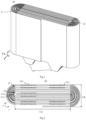
- FIG. 1 is a schematic diagram of an electrode assembly according to an embodiment of the present application
- FIG. 2 is a top view of the electrode assembly in FIG. 1
- FIG. 3 is a front view of the electrode assembly in FIG. 1
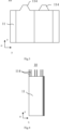
- FIG. 4 is a side view of the electrode assembly in FIG. 1 .
- the embodiment of the present application provides a wound electrode assembly 10, and the electrode assembly 10 includes an electrode plate 11 and a separator 12.
- the electrode plate 11 includes a positive electrode plate 111 and a negative electrode plate 112.
- the separator 12 is attached to the electrode plate 11 and located at a bent region 11b of the electrode plate 11, wherein the separator 12 can be attached to the positive electrode plate 111 or the negative electrode plate 112.
- the bent region 11b refers to a position where the electrode plate 11 is bent during winding.
- the electrode plate 11 includes a flat region 11a and a bent region 11b, the electrode plate 11 is not bent in the flat region 11a, and the electrode plate 11 extends in the flat region 11a in a first direction, such as a y direction; and an extension direction of the electrode plate 11 changes at two ends of the first direction, that is, the electrode plate 11 is bent at the bent region 11b.
- the separator 12 is located in the bent region 11b of the electrode plate 11, and the separator 12 may completely cover the electrode plate 11 in the bent region 11b, or partially cover the electrode plate 11 in the bent region 11b.
- the electrode plate 11 in the bent region 11b may be semicircular, elliptical or may be approximately semicircular or elliptical.
- the separator 12 loses the viscosity between the separator and the electrode plate 11 within a preset time.
- the preset time is related to the properties of the separator 12 itself, and the preset time may also be specifically set according to actual needs.
- the separation film, the positive electrode plate 111 and the negative electrode plate 112 are wound into an approximately elliptical roll by a winding mechanism, and the roll is then reshaped by a reshaping mechanism, thereby completing the preparation of the wound electrode assembly 10.
- the preset time may be a period of time from the attachment of the separator 12 to the electrode plate 11 to the completion of roll preparation (before roll reshaping).
- the separator 12 Before the electrode plate 11 and the separation film are wound by the winding mechanism, there is viscosity between the separator 12 and the electrode plate 11, such that the separator 12 is fixed at a corresponding position of the electrode plate 11; and after the electrode plate 11 and the separation film are wound by the winding mechanism, the separator 12 loses the viscosity between the separator and the electrode plate 11.
- the separator 12 is already fixed in place, that is, at the bent region 11b between the positive electrode plate 111 and the negative electrode plate 112. In this case, the separator 12 loses the viscosity between the separator and the electrode plate 11, and the separator 12 also does not fall off from the electrode plate 11.
- the preset time may also be a period of time from the attachment of the separator 12 to the electrode plate 11 to the completion of roll reshaping.
- the separator 12 loses the viscosity between the separator and the electrode plate 11 within the preset time, so that the influence of the viscosity on the electrode plate 11 can be avoided. For example, it is possible to avoid wrinkling of the electrode plate 11 caused by reshaping or stress unevenness of the electrode plate due to the viscosity. For another example, it is possible to avoid side reactions between the viscous separator 12 and an electrolyte solution in the battery. For another example, it is possible to prevent the viscous separator 12 from adsorbing ions, sodium ions or lithium ions, etc. to a position between the separator 12 and the electrode plate 11 to which the separator 12 is attached. This is beneficial to prolonging the service life of the battery, increasing the energy density of the battery, etc.
- the electrode assembly 10 further includes a tab 114, and the tab 114 may be connected to a housing for accommodating the electrode assembly 10.
- the wound electrode assembly 10 includes the electrode plate 11 and the separator 12.
- the separator 12 is attached to the electrode plate 11 and located in the bent region 11b of the electrode plate 11, such that the phenomenon can be avoided or reduced that deintercalated ions of the positive electrode plate 111 are intercalated into the negative electrode plate 112 through the separator 12, thereby avoiding various phenomena such as the lithium and sodium precipitation caused by the lack of vacancies in the negative electrode plate 112.
- the separator 12 loses the viscosity between the separator and the electrode plate 11 within the preset time, thereby avoiding wrinkling of the electrode plate 11 during subsequent reshaping and other processes due to the viscosity between the separator 12 and the electrode plate 11. Therefore, the performance of the battery can be improved with the technical solution of the present application.
- the bent region 11b of the electrode plate 11 includes a first surface 1111 and a second surface 1112 that are oppositely arranged, and the separator 12 is attached to the first surface 1111 and/or the second surface 1112 of the bent region 11b of the electrode plate 11.
- the first surface 1111 and the second surface 1112 are oppositely arranged in a thickness direction of the electrode plate 11.
- the first surface 1111 and the second surface 1112 of the positive electrode plate 111 respectively face the negative electrode plate 112 adjacent to the positive electrode plate 111
- the first surface 1111 and the second surface 1112 of the negative electrode plate 112 respectively face the positive electrode plate 111 adjacent to the negative electrode plate 112.
- the separator 12 may be attached to only the first surface 1111 of the bent region 11b of the electrode plate 11, may be attached to only the second surface of the bent region 11b of the electrode plate 11, or may be attached to both the first surface 1111 and the second surface 1112 of the bent region 11b of the electrode plate 11. In this way, it is convenient to select the attachment positions and number of the separators 12 according to actual needs, so as to obtain an electrode assembly 10 having a corresponding thickness according to the actual needs and to achieve a corresponding isolation effect.
- the electrode plate 11 includes the positive electrode plate 111, and the separator 12 is attached to the first surface 1111 and/or the second surface 1112 of the bent region 11b of the positive electrode plate 111.
- the negative electrode plate 112 is closer to the center of the electrode assembly 10 than the positive electrode plate 111.
- the first turn of positive electrode plate 111 is farther away from the center of the electrode assembly 10 than the first turn of negative electrode plate 112, in other words, the perimeter of the first turn of positive electrode plate 111 is greater than the perimeter of the first turn of negative electrode plate 112.
- the first surface 1111 of the bent region 11b of the positive electrode plate 111 may be a convex surface of the positive electrode plate 111, and with regard to the positive electrode plate 111 and the negative electrode plate 112 at the position where the two electrode plates have the same number of turns, the convex surface may be a surface of the positive electrode plate 111 away from the negative electrode plate 112.
- the second surface 1112 of the bent region 11b of the positive electrode plate 111 may be a concave surface of the positive electrode plate 111, and with regard to the positive electrode plate 111 and the negative electrode plate 112 at the position where the two electrode plates have the same number of turns, the concave surface may be a surface of the positive electrode plate 111 facing the negative electrode plate 112.
- the positive electrode plate 111 has a greater area than the negative electrode plate 112, resulting in that the number of the ions deintercalated from the positive electrode plate 111 is greater than the number of vacancies for accommodating ions in the negative electrode plate 112.
- the separator 12 By arranging the separator 12 at the bent region 11b of the positive electrode plate 111, ions can be prevented from being intercalated into the negative electrode plate 112 through the separator 12, thereby avoiding various phenomena such as lithium and sodium precipitation.
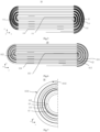
- FIG. 5 is a schematic diagram of an electrode assembly according to an embodiment of the present application.
- the separator 12 is attached to the convex surface and the concave surface of the bent region 11b of the positive electrode plate 111.
- the separator 12 By providing the separator 12 on the convex surface and the concave surface at the bent region 11b of the positive electrode plate 111, it is possible to more fully prevent the ions from passing through the separator 12.
- FIG. 6 is a schematic diagram of an electrode assembly according to an embodiment of the present application.
- the separator 12 is attached to the concave surface of the bent region 11b of the positive electrode plate 111.
- the separator 12 By arranging the separator 12 on the concave surface of the bent region 11b of the positive electrode plate 111, lithium or sodium precipitation can be avoided in the bent region 11b of the negative electrode plate 112, and meanwhile, it is beneficial to decreasing the overall thickness and size of the electrode assembly 10.
- the separator 12 may also be attached to the convex surface of the bent region 11b of the negative electrode plate 111. That is to say, the separator 12 may be attached to the positive electrode plate 111, or may be attached to both the positive electrode plate 111 and the negative electrode plate 112, for example, by means of adhesion.
- the separator 12 is arranged on the convex surface and the concave surface of the bent region 11b of the negative electrode plate 112, that is, the two surfaces of the negative electrode plate 112 are each provided with the separator 12 at the bent region 11b.
- the electrode assembly 10 includes N turns of positive electrode plate 111, and the separator 12 is arranged at the bent region 11b of 1 to 5 turns of the positive electrode plate 111 close to the center of the electrode assembly 10, wherein N ⁇ 5.
- the number of turns of the positive electrode plate 111 and the negative electrode plate 112 may be specifically set according to actual needs, for example, 20-100 turns.
- FIG. 7 is a schematic diagram of an electrode assembly according to an embodiment of the present application.
- the electrode assembly 10 further includes a separation film 13, and the separation film 13 is located between the positive electrode plate 111 and the negative electrode plate 112 to isolate the positive electrode plate 111 from the negative electrode plate 112; and the separator 12 is connected to the separation film 13.
- the separation film 13 is provided with gaps, and ions (such as lithium ions and sodium ions) can move between the positive electrode plate 111 and the negative electrode plate 112 through the separation film 13, thereby implementing a normal operation of the electrode assembly 10 or the battery.
- ions such as lithium ions and sodium ions
- the separator 12 is connected to the separation film 13, and the separator 12 may be located between the separation film 13 and the electrode plate 11.
- the separator 12 By arranging the separator 12, the ions can be prevented from passing through the separator 12 from the positive electrode plate 111, and thus the ions does not pass through the separation film 13 corresponding to the separator 12.
- the ions can escape from the positive electrode plate 111, and are intercalated into the negative electrode plate 112 after passing through the separation film 13.
- the separator 12 is configured to prevent the ions deintercalated from the positive electrode plate 111 from passing through the separator 12. In this way, the phenomena such as lithium and sodium precipitation at the bent region 11b of the negative electrode plate 112 can be avoided, and thus the safety of the battery can be improved.
- the separator 12 loses its viscosity within a preset time after being irradiated by light of a preset wavelength band. In this way, the separator 12 can lose the viscosity within the preset time by means of irradiation with the light of the preset wavelength band.
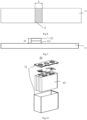
- FIG. 8 is a schematic diagram of an electrode plate attached with a separator according to an embodiment of the present application
- FIG. 9 is a schematic diagram of an electrode plate attached with a separator according to an embodiment of the present application.
- the separator 12 includes a base 121 and a time-delay adhesive 122 applied to the base, wherein the time-delay adhesive 122 is located between the base 121 and the electrode plate 11, and the time-delay adhesive 122 loses the viscosity within the preset time after being irradiated by the light of a preset wavelength band, such that the separator 12 loses the viscosity between the separator and the electrode plate 11 within the preset time. In this way, the separator can lose the viscosity within the preset time by using the time-delay adhesive, which is easy to implement.
- a material of the base 121 is at least one of a fiber, a polymer, polypropylene, polyethylene, rubber, and a non-woven fabric. The material is available, so the separator 12 is convenient to prepare.
- the material of the base 121 may be polyester, Teflon, etc.
- the base 121 is a base of a non-porous structure, such that the ions such as lithium ions cannot enter and pass through the base 121.
- the base 121 may also be a base with a certain microporous structure as long as the ions such as the lithium ions can be prevented from passing through the base.
- the time-delay adhesive 122 is an ultraviolet time-delay adhesive or an infrared time-delay adhesive.
- the adhesive is available, so the separator 12 is convenient to prepare.
- the time-delay adhesive 122 can prevent the ions such as the lithium ions from passing through.
- the separator 12 has a thickness d1 of 3 ⁇ m-2 cm.
- the thickness of the separator 12 may be 3 ⁇ m, 100 ⁇ m, 0.2 cm, 1 cm, 2 cm, etc.
- the thickness d1 of the separator 12 By setting the thickness d1 of the separator 12 to be 3 ⁇ m-2 cm, it is possible to prevent a preparation process from being complex due to a too small thickness of the separator 12, and it is also possible to avoid an excessive thickness of the electrode assembly 10 caused by an excessive thickness of the separator 12.
- the separator 12 having an appropriate thickness can also ensure the isolation performance of the separator 12.
- the separator 12 has a width k of 0.1 cm-20 cm, and the width of the separator 12 is a dimension in a bending direction of the electrode plate 11.
- the width of the separator 12 may be set according to a specific need as well as the dimension of the bent region 11b of the electrode plate 11.
- the width of the separator 12 may be 0.1 cm, 1 cm, 5 cm, 10 cm, 15 cm, 20 cm, etc.
- FIG. 10 is a schematic diagram of a battery cell according to an embodiment of the present application. As shown in FIG. 10 , the present application provides a battery cell 20, including the wound electrode assembly 10 and a housing 21 described above, the housing 21 being configured to accommodate the electrode assembly 10.
- FIG. 11 is a schematic diagram of a battery according to an embodiment of the present application. As shown in FIG. 11 , the present application provides a battery 1, including the battery cell 20 and a case 11 described above, the case 11 being configured to accommodate the battery cell 20.
- FIG. 12 is a schematic diagram of a power consuming device according to an embodiment of the present application.
- the present application provides a power consuming device 30, including the battery 1 described above, the battery 1 being configured to supply power to the power consuming device 30.
- the power consuming device 30 may be a vehicle, which may be a fuel vehicle, a gas vehicle, or a new energy vehicle.
- the new energy vehicle may be a battery electric vehicle, a hybrid electric vehicle, or an extended-range vehicle, etc.
- the vehicle may be internally provided with a motor 400, a controller 300 and a battery 1.
- the controller 300 is configured to control the battery 1 to supply power to the motor 400.
- the battery 1 may be arranged at the bottom or the head or the tail of the vehicle.
- the battery 1 may be configured to supply power to the vehicle.
- the battery 10 can serve as a power source for operating the vehicle for use in a circuit system of the vehicle, for example, to meet the working power demand of the vehicle during startup, navigation and traveling.
- the battery 1 can not only serve as a power source for operating the vehicle, but also serve as a power source for driving the vehicle, instead of or partially instead of fuel or natural gas, to provide driving power for the vehicle.
- FIG. 13 is a schematic diagram of a winding apparatus according to an embodiment of the present application. As shown in FIG. 13 , the present application provides a winding apparatus 50 for preparing a wound electrode assembly 10.
- the winding apparatus 50 includes a first conveying shaft 51 and an irradiation device 52.
- the first conveying shaft 51 is configured to convey the electrode plate 11, and the electrode plate 11 is attached with the separator 12.
- the first conveying shaft 51 may convey the positive electrode plate 111 or the negative electrode plate 112.
- the length of the first conveying shaft 51 may be specifically set according to the size of the electrode plate 11, which is not specifically limited by the present application.
- the irradiation device 52 is configured to irradiate the separator 12 attached to the electrode plate 11, such that the separator 12 loses the viscosity between the separator and the electrode plate 11 within a preset time.
- the separator 12 is irradiated by the irradiation device 52, and the separator 12 loses the viscosity between the separator and the electrode plate 11 within the preset time, such that the electrode plate 11 can be prevented from wrinkling due to the viscosity in a subsequent reshaping process, which is beneficial to improving the performance of the electrode assembly 10 and the battery.
- FIG. 14 is a schematic diagram of a winding apparatus according to an embodiment of the present application.
- the irradiation device 52 is arranged inside the first conveying shaft 51 and configured to irradiate the separator 12 when the first conveying shaft 51 conveys the electrode plate 11.
- the irradiation device 52 is arranged in the first conveying shaft 51, so that a space occupied by the irradiation device 52 can be saved on.
- the first conveying shaft 51 includes a first half shaft 511 and a second half shaft 512.
- the irradiation device 52 is arranged in the first half shaft 511. That is to say, the first half shaft 511 is internally provided with a hollow structure for accommodating the irradiation device 511.
- the irradiation device 52 may be arranged on a rotatable fixing shaft, the fixing shaft is arranged inside the first conveying shaft 51, and the first conveying shaft 51 is driven to rotate by the fixing shaft so as to convey the electrode plate 11.
- the irradiation device 52 is connected to the first half shaft 511 by means of a snap-fit structure.
- the irradiation device 52 is provided with a catch
- the first half shaft 511 is provided with a slot corresponding to the catch
- the irradiation device 52 is connected to the first half shaft 511 by means of the fitting between the catch and the slot.
- the irradiation device 52 may also be connected to the first half shaft 511 by a built-in bolt or by means of adhesion.
- the second half shaft 512 is connected to the first half shaft 511, the second half shaft 512 is provided with a light-transmitting region 513, and the light-transmitting region 513 is arranged corresponding to the irradiation device 52, such that light from the irradiation device 52 is emitted through the light-transmitting region 513.
- the light-transmitting region 513 may be made of a high polymer, an acrylic plate, organic glass and other materials.
- the second half shaft 512 is entirely made of a transparent material.
- the light emitted by the irradiation device 52 located in the first conveying shaft 51 can be emitted through the light-transmitting region 513, thereby ensuring that the separator 12 can be irradiated by the irradiation device 52.
- first half shaft 511 and the second half shaft 512 are provided with snap-fit structures 514, and the first half shaft 511 and the second half shaft 512 are snap-fitted by means of the snap-fit structures 514.
- an inner wall of the first half shaft 511 is provided with a slot 514a
- an inner wall of the second half shaft 512 is provided with a catch 514b corresponding to the slot 514a
- the snap-fitting of the first half shaft 511 and the second half shaft 512 is implemented by means of the snap-fitting of the slot 514a and the catch 514b.
- connection between the first half shaft 511 and the second half shaft 512 is achieved by means of the built-in snap-fit structures 514 while the conveying of the electrode plate 11 by the first conveying shaft 51 is not affected.
- first half shaft 511 and the second half shaft 512 are connected by means of a hinge joint, adhesion, bolt connection, etc.
- a shaft wall of the first half shaft 5111 and/or the second half shaft 512 has a thickness of 0.5 cm-18 cm. In this way, both the structural strength and the size of the first half shaft 511 and the second half shaft 512 can be taken into account.
- the thickness d2 of the shaft wall is a maximum distance between an outer wall and the inner wall of the first half shaft 511 or the second half shaft 512.
- the outer wall is an outer surface of the first half shaft 511 or the second half shaft 512 in contact with the electrode plate 11
- the inner wall is an inner surface of the first half shaft 511 or the second half shaft 512, which is in contact with the irradiation device 52 or faces the irradiation device 52.
- the winding apparatus 50 further includes a control unit 53 and a distance measurement mechanism 54.
- the distance measurement mechanism 54 is configured to measure a first length, and the first length is a length by which the electrode plate 11 passes through the first conveying shaft 51.
- the distance measurement mechanism 54 may be arranged on the first conveying shaft 51, such that the length by which the electrode plate 11 is conveyed by the first conveying shaft 51 can be measured.
- the distance measurement mechanism 54 is arranged at a certain distance from the first conveying shaft 51, and the length by which the electrode plate 11 passes through the first conveying shaft 51 can be determined according to the data measured by the distance measurement mechanism 54.
- the distance measurement mechanism 54 may also sense the number of tabs, marks on the tabs, etc., and the distance measurement mechanism 54 may determine the position of the separator 12 according to the number of tabs.
- the control unit 53 is configured to control the irradiation device 52 to be turned on or off according to the first length.
- the separator 12 is arranged at a specific position of the electrode plate 11, and it can be determined according to the first length whether the separator 12 is conveyed to a corresponding position of the irradiation device 52.
- the control unit 53 can determine, according to the first length, whether a portion of the electrode plate to which the separator 12 is attached has been conveyed to the first conveying shaft 51 or is about to be conveyed to the first conveying shaft 51, such that the control unit 53 controls the on/off of the irradiation device 52. If the portion of the electrode plate to which the separator 12 is attached has passed through the first conveying shaft 51, the control unit 53 may control the irradiation device 52 to be turned off.
- control unit 53 may control the irradiation device 52 to be turned on or off according to the data measured by the distance measurement mechanism 54.
- the distance measurement mechanism 54 may be cylindrical, cubic, elliptical, etc.
- the winding apparatus 50 further includes a color sensing mechanism 55, and the color sensing mechanism 55 is configured to sense the color of the separator 12 or the electrode plate 11; and the control unit 53 is configured to control the irradiation device 52 to be turned on or off according to the color sensed by the color sensing mechanism 55.
- the separator 12 and the electrode plate 11 may have different colors, and when the color sensing mechanism 55 senses the color of the separator 12, the control unit 53 may control the irradiation device 52 to be turned on. In this way, by arranging the color sensing mechanism 55 and the distance measurement mechanism 54, the accuracy of sensing the separator 12 can be further improved, so as to control the irradiation device 52 to be turned on in a timely manner.
- control unit 53 can control the irradiation device 52 to be turned off.
- control unit 53, the color sensing mechanism 55 and the distance measurement mechanism 54 are arranged in the irradiation device 52.
- the irradiation device 52 may also be an intelligent irradiation device with distance and color sensing functions. In this way, the space occupied by the winding apparatus 50 can be saved on, and the irradiation device 52 can also be convenient to prepare.
- the irradiation device 52 is an ultraviolet self-adaptive timer lamp, which can be automatically turned on or off according to a preset time interval.
- FIG. 15 is a schematic diagram of a winding apparatus in use according to an embodiment of the present application.
- the separator 12 is attached to the surface of the positive electrode plate 111, and the first conveying shaft 51 is configured to convey the positive electrode plate 111.
- the winding apparatus 50 is an apparatus in which the first conveying shaft 51 and the irradiation device 52 are integrated.
- the winding apparatus 50 is configured to convey the positive electrode plate 111, the separators 12 are attached to two surfaces of the positive electrode plate 111, and the separators 12 on the two surfaces of the positive electrode plate 111 can be irradiated by means of two winding apparatuses 50.
- the separators 12 attached to the positive electrode plate 111 are irradiated by using the winding apparatuses 50, the positive electrode plate 111 attached with the separators 12, the separation film 113 and the negative electrode plate 112 are wound and reshaped by a winding needle, thereby forming the wound electrode assembly 10.
- the separators 12 are located in the bent region 11b of the electrode plate 11.
- the lithium precipitation can be avoided or reduced by arranging the separators 12.
- the separator 12 includes a base 121 and a time-delay adhesive 122 applied to the base 121, wherein the time-delay adhesive 122 is located between the base 121 and the electrode plate 11, and the time-delay adhesive 122 loses the viscosity within the preset time after being irradiated by the irradiation device 52, such that the separator 12 loses the viscosity between the separator and the electrode plate 11 within the preset time. In this way, the separator 12 can lose the viscosity within the preset time by using the time-delay adhesive 122 and the corresponding irradiation device 52, which is easy to implement.
- the irradiation device 52 is an ultraviolet lamp irradiation device or an infrared lamp irradiation device.
- a lamp tube 56 is arranged in the irradiation device, and the lamp tube may be an ultraviolet lamp tube or an infrared lamp tube; and the irradiation device 52 can emit ultraviolet light by means of the ultraviolet lamp tube, and emit infrared light by means of the infrared lamp tube.
- the irradiation device 52 is an ultraviolet lamp irradiation device or an infrared lamp irradiation device, so the irradiation device 52 is easily obtained.
- the first conveying shaft 51 has a diameter d3 of 1.5 cm-20 cm.
- the diameter of the first conveying shaft 51 may be 1.5 cm, 2 cm, 3 cm, 5 cm, 10 cm, 15 cm, 20 cm, etc.
- the first conveying shaft 51 is convenient to machine, and meanwhile, it is also convenient to arrange the first conveying shaft 51 according to the size of the electrode plate 11, such that the first conveying shaft 51 can conveniently convey the electrode plate 11.
- the separator 12 has a thickness d1 of 3 ⁇ m-2 cm. In this way, both the performance of the separator 12 and the size of the electrode assembly 10 can be taken into account.
- the present application provides a winding apparatus 50, including a first conveying shaft 51 and an irradiation device 52.
- the first conveying shaft 51 is configured to convey the electrode plate 11, and the electrode plate 11 is attached with the separator 12.
- the irradiation device 52 is configured to irradiate the separator 12 attached to the electrode plate 11, such that the separator 12 loses the viscosity between the separator and the electrode plate 11 within a preset time.
- the wound electrode assembly 10 can be prepared by means of the winding apparatus 50, and the electrode assembly 10 includes an electrode plate 11 and a separator 12.
- the separator 12 is attached to the electrode plate 11 and located in the bent region 11b of the electrode plate 11, such that the phenomenon can be avoided or reduced that deintercalated ions of the positive electrode plate 111 are intercalated into the negative electrode plate 112 through the separator, thereby avoiding various phenomena such as the lithium precipitation caused by the lack of vacancies in the negative electrode plate 112.
- the separator 12 loses the viscosity between the separator and the electrode plate 11 within the preset time, thereby avoiding wrinkling of the electrode plate 11 during subsequent reshaping and other processes due to the viscosity between the separator 12 and the electrode plate 11. Therefore, the performance of the battery can be improved with the technical solution of the present application.
Landscapes
- Chemical & Material Sciences (AREA)
- Chemical Kinetics & Catalysis (AREA)
- Electrochemistry (AREA)
- General Chemical & Material Sciences (AREA)
- Engineering & Computer Science (AREA)
- Manufacturing & Machinery (AREA)
- Organic Chemistry (AREA)
- Physics & Mathematics (AREA)
- General Physics & Mathematics (AREA)
- Secondary Cells (AREA)
- Cell Separators (AREA)
Abstract
Description
- The present application relates to the technical field of technical batteries, and in particular, to a wound electrode assembly, a battery cell, a battery, a power consuming device, and a winding apparatus.
- With the development of battery technologies, there are increasing requirements on all aspects of batteries. For example, while performance parameters such as energy density, cycling life, discharge capacity and charge-discharge rate are considered, the safety of the batteries also needs to be taken into account. The precipitation of metal ions in the batteries, such as lithium precipitation, is one of the main factors affecting the electrical performance and safety performance of the batteries. Once the lithium precipitation occurs, not only will the electrical performance of the battery be reduced, but also it is likely to form dendrites with the accumulation of precipitated lithium. The dendrites may puncture a separation film to cause a short circuit in the battery, resulting in a safety hazard.
- Therefore, how to provide a battery assembly in order to improve the performance of a battery is a technical problem that needs to be urgently solved.
- The present application provides a wound electrode assembly, a battery cell, a battery, a power consuming device and a winding apparatus, which can improve the safety performance of the battery.
- In a first aspect, the present application provides a wound electrode assembly, including: an electrode plate; and a separator attached to the electrode plate and located in a bent region of the electrode plate, the separator losing viscosity between the separator and the electrode plate within a preset time.
- In an embodiment of the present application, the wound electrode assembly includes the electrode plate and the separator. The separator is attached to the electrode plate and located in the bent region of the electrode plate, such that the phenomenon can be avoided or reduced that deintercalated ions of a positive electrode plate are intercalated into a negative electrode plate through the separator, thereby avoiding various phenomena such as lithium precipitation caused by the lack of vacancies in the negative electrode plate. The separator loses the viscosity between the separator and the electrode plate within the preset time, thereby avoiding wrinkling of the electrode plate during subsequent reshaping and other processes due to the viscosity between the separator and the electrode plate. Therefore, the performance of the battery can be improved with the technical solution of the present application.
- In a possible implementation, the bent region of the electrode plate includes a first surface and a second surface that are oppositely arranged, and the separator is attached to the first surface and/or the second surface of the bent region of the electrode plate. In this way, it is convenient to flexibly set a position of the separator according to actual needs, and it is beneficial to taking into account the thickness of the electrode assembly and an isolation effect of the separator.
- In a possible implementation, the electrode plate includes a positive electrode plate, and the separator is attached to the first surface and/or the second surface of the bent region of the positive electrode plate. In the wound electrode assembly, with regard to the positive electrode plate and the negative electrode plate at a position where the two electrode plates have the same number of turns, the negative electrode plate is closer to the center of the electrode assembly than the positive electrode plate. Therefore, in the bent region, the positive electrode plate has a greater area than the negative electrode plate, resulting in that the number of ions deintercalated from the positive electrode plate is greater than the number of vacancies for accommodating ions in the negative electrode plate. By arranging the separator on the first surface and/or the second surface of the bent region of the positive electrode plate, the ions can be prevented from passing through the separator, thereby avoiding the occurrence of phenomena such as lithium precipitation.
- In a possible implementation, the electrode assembly includes N turns of positive electrode plate, and the separator is arranged at the bent region of 1 to 5 turns of the positive electrode plate close to the center of the electrode assembly, where N ≥ 5. The farther away from the center of the electrode assembly, the smaller an area difference between the positive electrode plate and the negative electrode plate at the bent region, and the less prone to causing lithium precipitation at the bent region of the negative electrode plate. Therefore, by arranging the separator at the bent region of 1 to 5 turns of the positive electrode plate close to the center of the electrode assembly, the lithium precipitation can be avoided, the thickness of the electrode assembly can also be decreased, and the size of the electrode assembly can thus be decreased, which is beneficial to increasing the volumetric energy density of the battery.
- In a possible implementation, the electrode assembly further includes a separation film, and the separation film is located between the positive electrode plate and the negative electrode plate to isolate the positive electrode plate from the negative electrode plate; and the separator is connected to the separation film. That is to say, the separator is located between the separation film and the electrode plate. At a position where the separator is not arranged, ions can move between the positive electrode plate and the negative electrode plate through the separation film, thereby implementing a normal operation of the electrode assembly or the battery.
- In a possible implementation, the separator is configured to prevent ions deintercalated from the positive electrode plate from passing through the separator. In this way, the phenomena such as lithium precipitation at the bent region of the negative electrode plate can be avoided, and thus the safety of the battery can be improved.
- In a possible implementation, the separator loses the viscosity within the preset time after being irradiated with light of a preset wavelength band. In this way, the separator can lose the viscosity within the preset time by means of irradiation with the light of a preset wavelength band.
- In a possible implementation, the separator includes a base and a time-delay adhesive applied to the base, the time-delay adhesive is located between the base and the electrode plate, and the time-delay adhesive loses the viscosity within the preset time after being irradiated with light of a preset wavelength band, such that the separator loses the viscosity between the separator and the electrode plate within the preset time. In this way, the separator can lose the viscosity within the preset time by using the time-delay adhesive, which is easy to implement.
- In a possible implementation, a material of the base is at least one of a fiber, a polymer, polypropylene, polyethylene, rubber, and a non-woven fabric. The material is available, so the separator is convenient to prepare.
- In a possible implementation, the time-delay adhesive is an ultraviolet time-delay adhesive or an infrared time-delay adhesive. The adhesive is available, so the separator is convenient to prepare.
- In a possible implementation, the separator has a thickness of 3 µm-2 cm. In this way, both the performance of the separator and the size of the electrode assembly can be taken into account.
- In a second aspect, the present application provides a battery cell, including a housing and the wound electrode assembly in the first aspect and in any possible implementation thereof, the housing being configured to accommodate the electrode assembly.
- In a third aspect, the present application provides a battery, including a case and the battery cell in the second aspect, the case being configured to accommodate the battery cell.
- In a fourth aspect, the present application provides a power consuming device, including the battery in the third aspect, the battery being configured to supply power to the power consuming device.
- In a fifth aspect, the present application provides a winding apparatus for preparing a wound electrode assembly. The winding apparatus includes: a first conveying shaft for conveying an electrode plate, a separator being attached to the electrode plate; and an irradiation device for irradiating the separator attached to the electrode plate, such that the separator loses the viscosity between the separator and the electrode plate within a preset time. In this way, the separator is irradiated by the irradiation device, and the separator loses the viscosity between the separator and the electrode plate within the preset time, so that the electrode plate can be prevented from wrinkling due to the viscosity in a subsequent reshaping process.
- In a possible implementation, the irradiation device is arranged inside the first conveying shaft, and is configured to irradiate the separator when the first conveying shaft conveys the electrode plate. In this way, the irradiation device is arranged in the first conveying shaft, so that a space occupied by the irradiation device can be saved on.
- In a possible implementation, the first conveying shaft includes: a first half shaft, the irradiation device being arranged inside the first half shaft; and a second half shaft connected to the first half shaft, the second half shaft being provided with a light-transmitting region arranged corresponding to the irradiation device, such that light from the irradiation device is emitted through the light-transmitting region. In this way, the light emitted by the irradiation device located in the first conveying shaft can be emitted through the light-transmitting region, thereby ensuring that the separator can be irradiated by the irradiation device.
- In a possible implementation, the first half shaft and the second half shaft are provided with snap-fit structures, and the first half shaft and the second half shaft are snap-fitted by means of the snap-fit structures. In this way, the connection between the first half shaft and the second half shaft is achieved while the conveying of the electrode plates by the first conveying shaft is not affected.
- In a possible implementation, a shaft wall of the first half shaft and/or the second half shaft has a thickness of 0.5 cm to 18 cm. In this way, both the strength and the size of the first half shaft and the second half shaft can be taken into account.
- In a possible implementation, the winding apparatus further includes a control unit and a distance measurement mechanism; the distance measurement mechanism is configured to measure a first length, and the first length is a length by which the electrode plate passes through the first conveying shaft; and the control unit is configured to control the irradiation device to be turned on or off according to the first length. In this way, it is convenient to detect the separator in a timely manner and irradiate the separator.
- In a possible implementation, the winding apparatus further includes a color sensing mechanism for sensing the color of the separator or the electrode plate; and the control unit is configured to control the irradiation device to be turned on or off according to the color sensed by the color sensing mechanism. In this way, it is possible to detect the separator in a timely manner and irradiate the separator.
- In a possible implementation, the control unit, the color sensing mechanism and the distance measurement mechanism are arranged in the irradiation device. In this way, the space occupied by the winding apparatus can be saved on, and the irradiation device can also be convenient to prepare.
- In a possible implementation, the separator is attached to the surface of the positive electrode plate, and the first conveying shaft is configured to convey the positive electrode plate. In this way, after the positive electrode plate, the separation film and the negative electrode plate are wound to form the electrode assembly, the lithium precipitation can be avoided or reduced by arranging the separator.
- In a possible implementation, the separator includes a base and a time-delay adhesive applied to the base, the time-delay adhesive is located between the base and the electrode plate, and the time-delay adhesive loses the viscosity within the preset time after being irradiated by the irradiation device, such that the separator loses the viscosity between the separator and the electrode plate within the preset time. In this way, the separator can lose the viscosity within the preset time by using the time-delay adhesive and the corresponding irradiation device, which is easy to implement.
- In a possible implementation, the irradiation device is an ultraviolet lamp irradiation device or an infrared lamp irradiation device. In this way, the irradiation device is easily obtained.
- In a possible implementation, the first conveying shaft has a diameter of 1.5 cm-20 cm. In this way, the first conveying shaft is convenient to machine, and meanwhile, it is also convenient for the first conveying shaft to convey the electrode plate.
- In a possible implementation, the separator has a thickness of 3 µm-2 cm. In this way, both the performance of the separator and the size of the electrode assembly can be taken into account.
- In an embodiment of the present application, the wound electrode assembly includes the electrode plate and the separator. The separator is attached to the electrode plate and located in the bent region of the electrode plate, such that the phenomenon can be avoided or reduced that deintercalated ions of a positive electrode plate are intercalated into a negative electrode plate through the separator, thereby avoiding various phenomena such as lithium precipitation caused by the lack of vacancies in the negative electrode plate. The separator loses the viscosity between the separator and the electrode plate within the preset time, thereby avoiding wrinkling of the electrode plate during subsequent reshaping and other processes due to the viscosity between the separator and the electrode plate. Therefore, the performance of the battery can be improved with the technical solution of the present application.
- In order to more clearly illustrate the technical solutions of the embodiments of the present application, the accompanying drawings required in the embodiments of the present application will be briefly described below. Obviously, the accompanying drawings described below are merely some embodiments of the present application, and for those of ordinary skill in the art, other accompanying drawings can be obtained from these accompanying drawings without making creative efforts.
-
FIG. 1 is a schematic diagram of an electrode assembly according to an embodiment of the present application; -
FIG. 2 is a top view of the electrode assembly inFIG. 1 ; -
FIG. 3 is a front view of the electrode assembly inFIG. 1 ; -
FIG. 4 is a side view of the electrode assembly inFIG. 1 ; -
FIG. 5 is a schematic diagram of an electrode assembly according to an embodiment of the present application; -
FIG. 6 is a schematic diagram of an electrode assembly according to an embodiment of the present application; -
FIG. 7 is a schematic diagram of an electrode assembly according to an embodiment of the present application; -
FIG. 8 is a schematic diagram of an electrode plate attached with a separator according to an embodiment of the present application; -
FIG. 9 is a schematic diagram of an electrode plate attached with a separator according to an embodiment of the present application; -
FIG. 10 is a schematic diagram of a battery cell according to an embodiment of the present application; -
FIG. 11 is a schematic diagram of a battery according to an embodiment of the present application; -
FIG. 12 is a schematic diagram of a power consuming device according to an embodiment of the present application; -
FIG. 13 is a schematic diagram of a winding apparatus according to an embodiment of the present application; -
FIG. 14 is a schematic diagram of a winding apparatus according to an embodiment of the present application; and -
FIG. 15 is a schematic diagram of a winding apparatus in use according to an embodiment of the present application. - In the accompanying drawings, the figures are not drawn to scale.
- The implementations of the present application will be further described in detail below in conjunction with the accompanying drawings and embodiments. The following detailed description of the embodiments and the accompanying drawings are used to illustrate the principle of the present application by way of example and are not intended to limit the scope of the present application. That is, the present application is not limited to the described embodiments.
- In the description of the present application, it should be noted that "a plurality of" means two or more, unless otherwise specified. The orientation or position relationship indicated by the terms "upper", "lower", "left", "right", "inner", "outer", etc. is only for the convenience of describing the present application and simplifying the description, rather than indicating or implying that the device or element referred to must have a particular orientation or be constructed and operated in a particular orientation, and therefore should not be construed as a limitation on the present application. In addition, the terms "first", "second", "third", etc. are merely for descriptive purposes, and should not be construed as indicating or implying the relative importance. The term "perpendicular" does not mean being perpendicular in the strict sense, but within an allowable range of tolerance. The term "parallel" does not mean being parallel in the strict sense, but within an allowable range of tolerance.
- The orientation terms in the following description all indicate directions shown in the accompanying drawings, and do not limit the specific structure in the present application. In the description of the present application, it should also be noted that the terms "mounting", "connecting", and "connection" should be interpreted in the broad sense unless explicitly defined and limited otherwise. For example, the connection may be a fixed connection, a detachable connection, or an integral connection, or may be a direct connection, or an indirect connection by means of an intermediate medium. For those of ordinary skill in the art, the specific meanings of the terms mentioned above in the present application can be construed according to specific circumstances.
- The term "and/or" in the present application is merely a description of the associated relationship of associated objects, representing that three relationships may exist, for example, A and/or B, may be expressed as: only A exists, both A and B exist, and only B exists. In addition, the character "/" in the present application generally indicates that the associated objects before and after the character are in a relationship of "or".
- In the present application, a battery cell may include a lithium ion secondary battery, a lithium ion primary battery, a lithium-sulfur battery, a sodium-lithium ion battery, a sodium ion battery or a magnesium ion battery, etc., which is not limited in the embodiments of the present application. The battery cell may be cylindrical, flat, cuboid or in another shape, which will also not be limited in the embodiments of the present application. The battery cells are generally classified into three types depending on the way of package: cylindrical battery cells, prismatic battery cells and pouch battery cells, which is also not limited in the embodiment of the present application.
- A battery mentioned in embodiments of the present application refers to a single physical module including one or more battery cells to provide a higher voltage and capacity. For example, the battery mentioned in the present application may include a battery pack, etc. The battery generally includes a case for packaging one or more battery cells. The case can prevent liquid or other foreign matters from affecting charging or discharging of the battery cell(s).
- The battery cell includes an electrode assembly and an electrolyte solution. The electrode assembly is composed of a positive electrode plate, a negative electrode plate, and a separation film. The operation of the battery cell mainly relies on the movement of metal ions between the positive electrode plate and the negative electrode plate. The positive electrode plate includes a positive electrode current collector and a positive electrode active material layer. The positive electrode active material layer is coated on a surface of the positive electrode current collector, and the current collector not coated with the positive electrode active material layer protrudes from the current collector coated with the positive electrode active material layer and is used as a positive electrode tab. Taking a lithium ion battery as an example, the positive electrode current collector may be made of aluminum, and the positive electrode active material may be lithium cobalt oxide, lithium iron phosphate, ternary lithium, lithium manganate, etc. The negative electrode plate includes a negative electrode current collector and a negative electrode active material layer. The negative electrode active material layer is coated on a surface of the negative electrode current collector, and the current collector not coated with the negative electrode active material layer protrudes from the current collector coated with the negative electrode active material layer and is used as a negative electrode tab. The negative electrode current collector may be made of copper, and the negative electrode active material may be carbon, silicon, etc. In order to ensure that no fusing occurs when a large current passes, a plurality of positive electrode tabs are provided and are stacked together, and a plurality of negative electrode tabs are provided and are stacked together. A material of the separation film may be Polypropylene (PP) or Polyethylene (PE), etc.
- The battery may include a plurality of battery cells in order to meet different power demands, with the plurality of battery cells being in series connection, parallel connection or series-parallel connection. The series-parallel connection refers to a combination of series connection and parallel connection. Optionally, the plurality of battery cells may be in series connection or in parallel connection or in series-parallel connection to constitute a battery module, and then a plurality of battery modules may be in series connection or in parallel connection or in series-parallel connection to constitute the battery. That is to say, the plurality of battery cells may directly form a battery, or may form battery modules that may then form a battery. The battery is further arranged in a power consuming device to supply electric energy to the power consuming device.
- Design factors on many aspects need to be simultaneously considered for the development of the battery technology, such as energy density, cycling life, discharge capacity, charge-discharge rate, and other performance parameters. In addition, the safety of the battery needs to be taken into account. The precipitation of metal ions in the batteries, such as lithium precipitation, is one of the main factors affecting the electrical performance and safety performance of the batteries. Once the lithium precipitation occurs, not only will the electrical performance of the battery be reduced, but also it is likely to form dendrites with the accumulation of precipitated lithium. The dendrites may puncture a separation film to cause a short circuit in the battery, resulting in a safety hazard.
- The applicant found that in a wound electrode assembly, the curvature of the electrode plate is relatively large at a bent region of an electrode plate close to the center of the electrode assembly, and lithium precipitation and active material shedding are prone to occurring at the bent region of the electrode plate. In addition, during the reshaping of the electrode assembly, a gap between a positive electrode plate and a negative electrode plate becomes larger at the bent region, which will further aggravate the lithium precipitation and the formation of lithium dendrites. The above factors are not conducive to improving the performance of a battery.
- In view of this, the present application provides a wound electrode assembly, including: an electrode plate; and a separator attached to the electrode plate and located in a bent region of the electrode plate, the separator losing viscosity between the separator and the electrode plate within a preset time. In this way, the phenomenon can be avoided or reduced that deintercalated ions of a positive electrode plate are intercalated into a negative electrode plate through the separator, thereby avoiding various phenomena such as lithium precipitation caused by the lack of vacancies in the negative electrode plate. The separator loses the viscosity between the separator and the electrode plate within the preset time, thereby avoiding wrinkling of the electrode plate during subsequent reshaping and other processes due to the viscosity between the separator and the electrode plate. Therefore, the performance of the battery can be improved with the technical solution of the present application.
-
FIG. 1 is a schematic diagram of an electrode assembly according to an embodiment of the present application,FIG. 2 is a top view of the electrode assembly inFIG. 1 ,FIG. 3 is a front view of the electrode assembly inFIG. 1 , andFIG. 4 is a side view of the electrode assembly inFIG. 1 . As shown inFIGS. 1 to 4 , the embodiment of the present application provides awound electrode assembly 10, and theelectrode assembly 10 includes anelectrode plate 11 and aseparator 12. - The
electrode plate 11 includes apositive electrode plate 111 and anegative electrode plate 112. - The
separator 12 is attached to theelectrode plate 11 and located at abent region 11b of theelectrode plate 11, wherein theseparator 12 can be attached to thepositive electrode plate 111 or thenegative electrode plate 112. - The
bent region 11b refers to a position where theelectrode plate 11 is bent during winding. For example, theelectrode plate 11 includes aflat region 11a and abent region 11b, theelectrode plate 11 is not bent in theflat region 11a, and theelectrode plate 11 extends in theflat region 11a in a first direction, such as a y direction; and an extension direction of theelectrode plate 11 changes at two ends of the first direction, that is, theelectrode plate 11 is bent at thebent region 11b. - It should be noted that the
separator 12 is located in thebent region 11b of theelectrode plate 11, and theseparator 12 may completely cover theelectrode plate 11 in thebent region 11b, or partially cover theelectrode plate 11 in thebent region 11b. - The
electrode plate 11 in thebent region 11b may be semicircular, elliptical or may be approximately semicircular or elliptical. - The
separator 12 loses the viscosity between the separator and theelectrode plate 11 within a preset time. The preset time is related to the properties of theseparator 12 itself, and the preset time may also be specifically set according to actual needs. - In the process of preparing the
wound electrode assembly 10, after theseparator 12 is attached to theelectrode plate 11 by means of an adhesive application mechanism, the separation film, thepositive electrode plate 111 and thenegative electrode plate 112 are wound into an approximately elliptical roll by a winding mechanism, and the roll is then reshaped by a reshaping mechanism, thereby completing the preparation of thewound electrode assembly 10. The preset time may be a period of time from the attachment of theseparator 12 to theelectrode plate 11 to the completion of roll preparation (before roll reshaping). - Before the
electrode plate 11 and the separation film are wound by the winding mechanism, there is viscosity between theseparator 12 and theelectrode plate 11, such that theseparator 12 is fixed at a corresponding position of theelectrode plate 11; and after theelectrode plate 11 and the separation film are wound by the winding mechanism, theseparator 12 loses the viscosity between the separator and theelectrode plate 11. By means of the winding by the winding mechanism, theseparator 12 is already fixed in place, that is, at thebent region 11b between thepositive electrode plate 111 and thenegative electrode plate 112. In this case, theseparator 12 loses the viscosity between the separator and theelectrode plate 11, and theseparator 12 also does not fall off from theelectrode plate 11. - Optionally, the preset time may also be a period of time from the attachment of the
separator 12 to theelectrode plate 11 to the completion of roll reshaping. - The
separator 12 loses the viscosity between the separator and theelectrode plate 11 within the preset time, so that the influence of the viscosity on theelectrode plate 11 can be avoided. For example, it is possible to avoid wrinkling of theelectrode plate 11 caused by reshaping or stress unevenness of the electrode plate due to the viscosity. For another example, it is possible to avoid side reactions between theviscous separator 12 and an electrolyte solution in the battery. For another example, it is possible to prevent theviscous separator 12 from adsorbing ions, sodium ions or lithium ions, etc. to a position between theseparator 12 and theelectrode plate 11 to which theseparator 12 is attached. This is beneficial to prolonging the service life of the battery, increasing the energy density of the battery, etc. - Optionally, the
electrode assembly 10 further includes atab 114, and thetab 114 may be connected to a housing for accommodating theelectrode assembly 10. - In an embodiment of the present application, the
wound electrode assembly 10 includes theelectrode plate 11 and theseparator 12. Theseparator 12 is attached to theelectrode plate 11 and located in thebent region 11b of theelectrode plate 11, such that the phenomenon can be avoided or reduced that deintercalated ions of thepositive electrode plate 111 are intercalated into thenegative electrode plate 112 through theseparator 12, thereby avoiding various phenomena such as the lithium and sodium precipitation caused by the lack of vacancies in thenegative electrode plate 112. Theseparator 12 loses the viscosity between the separator and theelectrode plate 11 within the preset time, thereby avoiding wrinkling of theelectrode plate 11 during subsequent reshaping and other processes due to the viscosity between theseparator 12 and theelectrode plate 11. Therefore, the performance of the battery can be improved with the technical solution of the present application. - In an embodiment of the present application, the
bent region 11b of theelectrode plate 11 includes afirst surface 1111 and asecond surface 1112 that are oppositely arranged, and theseparator 12 is attached to thefirst surface 1111 and/or thesecond surface 1112 of thebent region 11b of theelectrode plate 11. - The
first surface 1111 and thesecond surface 1112 are oppositely arranged in a thickness direction of theelectrode plate 11. With regard to thepositive electrode plate 111, thefirst surface 1111 and thesecond surface 1112 of thepositive electrode plate 111 respectively face thenegative electrode plate 112 adjacent to thepositive electrode plate 111, and with regard to thenegative electrode plate 112, thefirst surface 1111 and thesecond surface 1112 of thenegative electrode plate 112 respectively face thepositive electrode plate 111 adjacent to thenegative electrode plate 112. - The
separator 12 may be attached to only thefirst surface 1111 of thebent region 11b of theelectrode plate 11, may be attached to only the second surface of thebent region 11b of theelectrode plate 11, or may be attached to both thefirst surface 1111 and thesecond surface 1112 of thebent region 11b of theelectrode plate 11. In this way, it is convenient to select the attachment positions and number of theseparators 12 according to actual needs, so as to obtain anelectrode assembly 10 having a corresponding thickness according to the actual needs and to achieve a corresponding isolation effect. - In an embodiment of the present application, the
electrode plate 11 includes thepositive electrode plate 111, and theseparator 12 is attached to thefirst surface 1111 and/or thesecond surface 1112 of thebent region 11b of thepositive electrode plate 111. - In the
wound electrode assembly 10, with regard to thepositive electrode plate 111 and thenegative electrode plate 112 at a position where the two electrode plates have the same number of turns, thenegative electrode plate 112 is closer to the center of theelectrode assembly 10 than thepositive electrode plate 111. For example, the first turn ofpositive electrode plate 111 is farther away from the center of theelectrode assembly 10 than the first turn ofnegative electrode plate 112, in other words, the perimeter of the first turn ofpositive electrode plate 111 is greater than the perimeter of the first turn ofnegative electrode plate 112. - The
first surface 1111 of thebent region 11b of thepositive electrode plate 111 may be a convex surface of thepositive electrode plate 111, and with regard to thepositive electrode plate 111 and thenegative electrode plate 112 at the position where the two electrode plates have the same number of turns, the convex surface may be a surface of thepositive electrode plate 111 away from thenegative electrode plate 112. - The
second surface 1112 of thebent region 11b of thepositive electrode plate 111 may be a concave surface of thepositive electrode plate 111, and with regard to thepositive electrode plate 111 and thenegative electrode plate 112 at the position where the two electrode plates have the same number of turns, the concave surface may be a surface of thepositive electrode plate 111 facing thenegative electrode plate 112. - At the
bent region 11b, with regard to thepositive electrode plate 111 and thenegative electrode plate 112 at the position where the two electrode plates have the same number of turns, thepositive electrode plate 111 has a greater area than thenegative electrode plate 112, resulting in that the number of the ions deintercalated from thepositive electrode plate 111 is greater than the number of vacancies for accommodating ions in thenegative electrode plate 112. By arranging theseparator 12 at thebent region 11b of thepositive electrode plate 111, ions can be prevented from being intercalated into thenegative electrode plate 112 through theseparator 12, thereby avoiding various phenomena such as lithium and sodium precipitation. -
FIG. 5 is a schematic diagram of an electrode assembly according to an embodiment of the present application. As shown inFIG. 5 , theseparator 12 is attached to the convex surface and the concave surface of thebent region 11b of thepositive electrode plate 111. By providing theseparator 12 on the convex surface and the concave surface at thebent region 11b of thepositive electrode plate 111, it is possible to more fully prevent the ions from passing through theseparator 12. -
FIG. 6 is a schematic diagram of an electrode assembly according to an embodiment of the present application. As shown inFIG. 6 , theseparator 12 is attached to the concave surface of thebent region 11b of thepositive electrode plate 111. By arranging theseparator 12 on the concave surface of thebent region 11b of thepositive electrode plate 111, lithium or sodium precipitation can be avoided in thebent region 11b of thenegative electrode plate 112, and meanwhile, it is beneficial to decreasing the overall thickness and size of theelectrode assembly 10. - Optionally, while the
separator 12 is attached to the concave surface of thebent region 11b of thepositive electrode plate 111, the separator may also be attached to the convex surface of thebent region 11b of thenegative electrode plate 111. That is to say, theseparator 12 may be attached to thepositive electrode plate 111, or may be attached to both thepositive electrode plate 111 and thenegative electrode plate 112, for example, by means of adhesion. - Optionally, the
separator 12 is arranged on the convex surface and the concave surface of thebent region 11b of thenegative electrode plate 112, that is, the two surfaces of thenegative electrode plate 112 are each provided with theseparator 12 at thebent region 11b. - In an embodiment of the present application, the
electrode assembly 10 includes N turns ofpositive electrode plate 111, and theseparator 12 is arranged at thebent region 11b of 1 to 5 turns of thepositive electrode plate 111 close to the center of theelectrode assembly 10, wherein N ≥ 5. - The farther away from the center of the
electrode assembly 10, the smaller an area difference between thepositive electrode plate 111 and thenegative electrode plate 112 at thebent region 11b, and the less prone to causing lithium precipitation at thebent region 11b of thenegative electrode plate 112. Therefore, by arranging theseparator 12 at thebent region 11b of 1 to 5 turns of thepositive electrode plate 111 close to the center of theelectrode assembly 10, the lithium precipitation can be avoided, the thickness of theelectrode assembly 10 can also be decreased, and the size of theelectrode assembly 10 can thus be decreased, which is beneficial to increasing the volumetric energy density of the battery. - In the
electrode assembly 10, the number of turns of thepositive electrode plate 111 and thenegative electrode plate 112 may be specifically set according to actual needs, for example, 20-100 turns. -
FIG. 7 is a schematic diagram of an electrode assembly according to an embodiment of the present application. In an embodiment of the present application, as shown inFIG. 7 , theelectrode assembly 10 further includes aseparation film 13, and theseparation film 13 is located between thepositive electrode plate 111 and thenegative electrode plate 112 to isolate thepositive electrode plate 111 from thenegative electrode plate 112; and theseparator 12 is connected to theseparation film 13. - The
separation film 13 is provided with gaps, and ions (such as lithium ions and sodium ions) can move between thepositive electrode plate 111 and thenegative electrode plate 112 through theseparation film 13, thereby implementing a normal operation of theelectrode assembly 10 or the battery. - The
separator 12 is connected to theseparation film 13, and theseparator 12 may be located between theseparation film 13 and theelectrode plate 11. By arranging theseparator 12, the ions can be prevented from passing through theseparator 12 from thepositive electrode plate 111, and thus the ions does not pass through theseparation film 13 corresponding to theseparator 12. - At a
non-bent region 11b or theflat region 11a of theelectrode plate 11, the ions can escape from thepositive electrode plate 111, and are intercalated into thenegative electrode plate 112 after passing through theseparation film 13. - In an embodiment of the present application, the
separator 12 is configured to prevent the ions deintercalated from thepositive electrode plate 111 from passing through theseparator 12. In this way, the phenomena such as lithium and sodium precipitation at thebent region 11b of thenegative electrode plate 112 can be avoided, and thus the safety of the battery can be improved. - In an embodiment of the present application, the
separator 12 loses its viscosity within a preset time after being irradiated by light of a preset wavelength band. In this way, theseparator 12 can lose the viscosity within the preset time by means of irradiation with the light of the preset wavelength band. -
FIG. 8 is a schematic diagram of an electrode plate attached with a separator according to an embodiment of the present application, andFIG. 9 is a schematic diagram of an electrode plate attached with a separator according to an embodiment of the present application. In an embodiment of the present application, as shown inFIGS. 8 and 9 , theseparator 12 includes abase 121 and a time-delay adhesive 122 applied to the base, wherein the time-delay adhesive 122 is located between the base 121 and theelectrode plate 11, and the time-delay adhesive 122 loses the viscosity within the preset time after being irradiated by the light of a preset wavelength band, such that theseparator 12 loses the viscosity between the separator and theelectrode plate 11 within the preset time. In this way, the separator can lose the viscosity within the preset time by using the time-delay adhesive, which is easy to implement. - In an embodiment of the present application, a material of the
base 121 is at least one of a fiber, a polymer, polypropylene, polyethylene, rubber, and a non-woven fabric. The material is available, so theseparator 12 is convenient to prepare. - For example, the material of the base 121 may be polyester, Teflon, etc.
- Optionally, the
base 121 is a base of a non-porous structure, such that the ions such as lithium ions cannot enter and pass through thebase 121. - Optionally, the
base 121 may also be a base with a certain microporous structure as long as the ions such as the lithium ions can be prevented from passing through the base. - In an embodiment of the present application, the time-
delay adhesive 122 is an ultraviolet time-delay adhesive or an infrared time-delay adhesive. The adhesive is available, so theseparator 12 is convenient to prepare. - Optionally, after the time-
delay adhesive 122 is cured, that is, after being irradiated with ultraviolet light or infrared light, the time-delay adhesive can prevent the ions such as the lithium ions from passing through. - In an embodiment of the present application, the
separator 12 has a thickness d1 of 3 µm-2 cm. For example, the thickness of theseparator 12 may be 3 µm, 100 µm, 0.2 cm, 1 cm, 2 cm, etc. - By setting the thickness d1 of the
separator 12 to be 3 µm-2 cm, it is possible to prevent a preparation process from being complex due to a too small thickness of theseparator 12, and it is also possible to avoid an excessive thickness of theelectrode assembly 10 caused by an excessive thickness of theseparator 12. In addition, theseparator 12 having an appropriate thickness can also ensure the isolation performance of theseparator 12. - Optionally, the
separator 12 has a width k of 0.1 cm-20 cm, and the width of theseparator 12 is a dimension in a bending direction of theelectrode plate 11. The width of theseparator 12 may be set according to a specific need as well as the dimension of thebent region 11b of theelectrode plate 11. For example, the width of theseparator 12 may be 0.1 cm, 1 cm, 5 cm, 10 cm, 15 cm, 20 cm, etc. -
FIG. 10 is a schematic diagram of a battery cell according to an embodiment of the present application. As shown inFIG. 10 , the present application provides abattery cell 20, including thewound electrode assembly 10 and ahousing 21 described above, thehousing 21 being configured to accommodate theelectrode assembly 10. -
FIG. 11 is a schematic diagram of a battery according to an embodiment of the present application. As shown inFIG. 11 , the present application provides abattery 1, including thebattery cell 20 and acase 11 described above, thecase 11 being configured to accommodate thebattery cell 20. -
FIG. 12 is a schematic diagram of a power consuming device according to an embodiment of the present application. As shown inFIG. 12 , the present application provides apower consuming device 30, including thebattery 1 described above, thebattery 1 being configured to supply power to thepower consuming device 30. Thepower consuming device 30 may be a vehicle, which may be a fuel vehicle, a gas vehicle, or a new energy vehicle. The new energy vehicle may be a battery electric vehicle, a hybrid electric vehicle, or an extended-range vehicle, etc. The vehicle may be internally provided with amotor 400, acontroller 300 and abattery 1. Thecontroller 300 is configured to control thebattery 1 to supply power to themotor 400. For example, thebattery 1 may be arranged at the bottom or the head or the tail of the vehicle. Thebattery 1 may be configured to supply power to the vehicle. For example, thebattery 10 can serve as a power source for operating the vehicle for use in a circuit system of the vehicle, for example, to meet the working power demand of the vehicle during startup, navigation and traveling. In another embodiment of the present application, thebattery 1 can not only serve as a power source for operating the vehicle, but also serve as a power source for driving the vehicle, instead of or partially instead of fuel or natural gas, to provide driving power for the vehicle. -
FIG. 13 is a schematic diagram of a winding apparatus according to an embodiment of the present application. As shown inFIG. 13 , the present application provides a windingapparatus 50 for preparing awound electrode assembly 10. The windingapparatus 50 includes a first conveyingshaft 51 and anirradiation device 52. - The first conveying
shaft 51 is configured to convey theelectrode plate 11, and theelectrode plate 11 is attached with theseparator 12. - The first conveying
shaft 51 may convey thepositive electrode plate 111 or thenegative electrode plate 112. The length of the first conveyingshaft 51 may be specifically set according to the size of theelectrode plate 11, which is not specifically limited by the present application. - The
irradiation device 52 is configured to irradiate theseparator 12 attached to theelectrode plate 11, such that theseparator 12 loses the viscosity between the separator and theelectrode plate 11 within a preset time. - In an embodiment of the present application, the
separator 12 is irradiated by theirradiation device 52, and theseparator 12 loses the viscosity between the separator and theelectrode plate 11 within the preset time, such that theelectrode plate 11 can be prevented from wrinkling due to the viscosity in a subsequent reshaping process, which is beneficial to improving the performance of theelectrode assembly 10 and the battery. -
FIG. 14 is a schematic diagram of a winding apparatus according to an embodiment of the present application. In an embodiment of the present application, as shown inFIG. 14 , theirradiation device 52 is arranged inside the first conveyingshaft 51 and configured to irradiate theseparator 12 when the first conveyingshaft 51 conveys theelectrode plate 11. In this way, theirradiation device 52 is arranged in the first conveyingshaft 51, so that a space occupied by theirradiation device 52 can be saved on. - In an embodiment of the present application, the first conveying
shaft 51 includes afirst half shaft 511 and asecond half shaft 512. - The
irradiation device 52 is arranged in thefirst half shaft 511. That is to say, thefirst half shaft 511 is internally provided with a hollow structure for accommodating theirradiation device 511. - Optionally, the
irradiation device 52 may be arranged on a rotatable fixing shaft, the fixing shaft is arranged inside the first conveyingshaft 51, and the first conveyingshaft 51 is driven to rotate by the fixing shaft so as to convey theelectrode plate 11. - Optionally, the
irradiation device 52 is connected to thefirst half shaft 511 by means of a snap-fit structure. For example, theirradiation device 52 is provided with a catch, and thefirst half shaft 511 is provided with a slot corresponding to the catch, and theirradiation device 52 is connected to thefirst half shaft 511 by means of the fitting between the catch and the slot. - Optionally, the
irradiation device 52 may also be connected to thefirst half shaft 511 by a built-in bolt or by means of adhesion. - The
second half shaft 512 is connected to thefirst half shaft 511, thesecond half shaft 512 is provided with a light-transmittingregion 513, and the light-transmittingregion 513 is arranged corresponding to theirradiation device 52, such that light from theirradiation device 52 is emitted through the light-transmittingregion 513. - The light-transmitting
region 513 may be made of a high polymer, an acrylic plate, organic glass and other materials. - Optionally, the
second half shaft 512 is entirely made of a transparent material. - In this embodiment, the light emitted by the
irradiation device 52 located in the first conveyingshaft 51 can be emitted through the light-transmittingregion 513, thereby ensuring that theseparator 12 can be irradiated by theirradiation device 52. - In an embodiment of the present application, the
first half shaft 511 and thesecond half shaft 512 are provided with snap-fit structures 514, and thefirst half shaft 511 and thesecond half shaft 512 are snap-fitted by means of the snap-fit structures 514. - For example, an inner wall of the
first half shaft 511 is provided with aslot 514a, an inner wall of thesecond half shaft 512 is provided with acatch 514b corresponding to theslot 514a, and the snap-fitting of thefirst half shaft 511 and thesecond half shaft 512 is implemented by means of the snap-fitting of theslot 514a and thecatch 514b. - In this embodiment, the connection between the
first half shaft 511 and thesecond half shaft 512 is achieved by means of the built-in snap-fit structures 514 while the conveying of theelectrode plate 11 by the first conveyingshaft 51 is not affected. - Optionally, the
first half shaft 511 and thesecond half shaft 512 are connected by means of a hinge joint, adhesion, bolt connection, etc. - In an embodiment of the present application, a shaft wall of the first half shaft 5111 and/or the
second half shaft 512 has a thickness of 0.5 cm-18 cm. In this way, both the structural strength and the size of thefirst half shaft 511 and thesecond half shaft 512 can be taken into account. - When the
first half shaft 511 and thesecond half shaft 512 are of hollow structures, the thickness d2 of the shaft wall is a maximum distance between an outer wall and the inner wall of thefirst half shaft 511 or thesecond half shaft 512. The outer wall is an outer surface of thefirst half shaft 511 or thesecond half shaft 512 in contact with theelectrode plate 11, and the inner wall is an inner surface of thefirst half shaft 511 or thesecond half shaft 512, which is in contact with theirradiation device 52 or faces theirradiation device 52. - In an embodiment of the present application, the winding
apparatus 50 further includes acontrol unit 53 and adistance measurement mechanism 54. - The
distance measurement mechanism 54 is configured to measure a first length, and the first length is a length by which theelectrode plate 11 passes through the first conveyingshaft 51. - The
distance measurement mechanism 54 may be arranged on the first conveyingshaft 51, such that the length by which theelectrode plate 11 is conveyed by the first conveyingshaft 51 can be measured. - Optionally, the
distance measurement mechanism 54 is arranged at a certain distance from the first conveyingshaft 51, and the length by which theelectrode plate 11 passes through the first conveyingshaft 51 can be determined according to the data measured by thedistance measurement mechanism 54. - Optionally, the
distance measurement mechanism 54 may also sense the number of tabs, marks on the tabs, etc., and thedistance measurement mechanism 54 may determine the position of theseparator 12 according to the number of tabs. - The
control unit 53 is configured to control theirradiation device 52 to be turned on or off according to the first length. - The
separator 12 is arranged at a specific position of theelectrode plate 11, and it can be determined according to the first length whether theseparator 12 is conveyed to a corresponding position of theirradiation device 52. - For example, when the
irradiation device 52 is arranged inside the first conveyingshaft 51, thecontrol unit 53 can determine, according to the first length, whether a portion of the electrode plate to which theseparator 12 is attached has been conveyed to the first conveyingshaft 51 or is about to be conveyed to the first conveyingshaft 51, such that thecontrol unit 53 controls the on/off of theirradiation device 52. If the portion of the electrode plate to which theseparator 12 is attached has passed through the first conveyingshaft 51, thecontrol unit 53 may control theirradiation device 52 to be turned off. - For another example, when the
irradiation device 52 and the first conveyingshaft 51 are arranged at different positions, thecontrol unit 53 may control theirradiation device 52 to be turned on or off according to the data measured by thedistance measurement mechanism 54. - In this embodiment, by arranging the
distance measurement mechanism 54 and thecontrol unit 53, it is convenient to detect theseparator 12 in a timely manner and irradiate theseparator 12. - Optionally, the
distance measurement mechanism 54 may be cylindrical, cubic, elliptical, etc. - In an embodiment of the present application, the winding
apparatus 50 further includes acolor sensing mechanism 55, and thecolor sensing mechanism 55 is configured to sense the color of theseparator 12 or theelectrode plate 11; and thecontrol unit 53 is configured to control theirradiation device 52 to be turned on or off according to the color sensed by thecolor sensing mechanism 55. - The
separator 12 and theelectrode plate 11 may have different colors, and when thecolor sensing mechanism 55 senses the color of theseparator 12, thecontrol unit 53 may control theirradiation device 52 to be turned on. In this way, by arranging thecolor sensing mechanism 55 and thedistance measurement mechanism 54, the accuracy of sensing theseparator 12 can be further improved, so as to control theirradiation device 52 to be turned on in a timely manner. - When the
color sensing mechanism 55 senses the color of theelectrode plate 11, thecontrol unit 53 can control theirradiation device 52 to be turned off. - In an embodiment of the present application, the
control unit 53, thecolor sensing mechanism 55 and thedistance measurement mechanism 54 are arranged in theirradiation device 52. Theirradiation device 52 may also be an intelligent irradiation device with distance and color sensing functions. In this way, the space occupied by the windingapparatus 50 can be saved on, and theirradiation device 52 can also be convenient to prepare. - Optionally, the
irradiation device 52 is an ultraviolet self-adaptive timer lamp, which can be automatically turned on or off according to a preset time interval. -
FIG. 15 is a schematic diagram of a winding apparatus in use according to an embodiment of the present application. In an embodiment of the present application, as shown inFIG. 15 , theseparator 12 is attached to the surface of thepositive electrode plate 111, and the first conveyingshaft 51 is configured to convey thepositive electrode plate 111. - As shown in
FIG. 15 , the windingapparatus 50 is an apparatus in which the first conveyingshaft 51 and theirradiation device 52 are integrated. The windingapparatus 50 is configured to convey thepositive electrode plate 111, theseparators 12 are attached to two surfaces of thepositive electrode plate 111, and theseparators 12 on the two surfaces of thepositive electrode plate 111 can be irradiated by means of two windingapparatuses 50. - Optionally, after the
separators 12 attached to thepositive electrode plate 111 are irradiated by using the windingapparatuses 50, thepositive electrode plate 111 attached with theseparators 12, the separation film 113 and thenegative electrode plate 112 are wound and reshaped by a winding needle, thereby forming thewound electrode assembly 10. Optionally, in the formedwound electrode assembly 10, theseparators 12 are located in thebent region 11b of theelectrode plate 11. - In this embodiment, after the
positive electrode plate 111, the separation film 113 and thenegative electrode plate 112 are wound to form theelectrode assembly 10, the lithium precipitation can be avoided or reduced by arranging theseparators 12. - In an embodiment of the present application, the
separator 12 includes abase 121 and a time-delay adhesive 122 applied to thebase 121, wherein the time-delay adhesive 122 is located between the base 121 and theelectrode plate 11, and the time-delay adhesive 122 loses the viscosity within the preset time after being irradiated by theirradiation device 52, such that theseparator 12 loses the viscosity between the separator and theelectrode plate 11 within the preset time. In this way, theseparator 12 can lose the viscosity within the preset time by using the time-delay adhesive 122 and thecorresponding irradiation device 52, which is easy to implement. - In an embodiment of the present application, the
irradiation device 52 is an ultraviolet lamp irradiation device or an infrared lamp irradiation device. For example, alamp tube 56 is arranged in the irradiation device, and the lamp tube may be an ultraviolet lamp tube or an infrared lamp tube; and theirradiation device 52 can emit ultraviolet light by means of the ultraviolet lamp tube, and emit infrared light by means of the infrared lamp tube. - In this embodiment, the
irradiation device 52 is an ultraviolet lamp irradiation device or an infrared lamp irradiation device, so theirradiation device 52 is easily obtained. - In an embodiment of the present application, the first conveying
shaft 51 has a diameter d3 of 1.5 cm-20 cm. For example, the diameter of the first conveyingshaft 51 may be 1.5 cm, 2 cm, 3 cm, 5 cm, 10 cm, 15 cm, 20 cm, etc. In this way, the first conveyingshaft 51 is convenient to machine, and meanwhile, it is also convenient to arrange the first conveyingshaft 51 according to the size of theelectrode plate 11, such that the first conveyingshaft 51 can conveniently convey theelectrode plate 11. - In an embodiment of the present application, the
separator 12 has a thickness d1 of 3 µm-2 cm. In this way, both the performance of theseparator 12 and the size of theelectrode assembly 10 can be taken into account. - The present application provides a winding
apparatus 50, including a first conveyingshaft 51 and anirradiation device 52. The first conveyingshaft 51 is configured to convey theelectrode plate 11, and theelectrode plate 11 is attached with theseparator 12. Theirradiation device 52 is configured to irradiate theseparator 12 attached to theelectrode plate 11, such that theseparator 12 loses the viscosity between the separator and theelectrode plate 11 within a preset time. Thewound electrode assembly 10 can be prepared by means of the windingapparatus 50, and theelectrode assembly 10 includes anelectrode plate 11 and aseparator 12. Theseparator 12 is attached to theelectrode plate 11 and located in thebent region 11b of theelectrode plate 11, such that the phenomenon can be avoided or reduced that deintercalated ions of thepositive electrode plate 111 are intercalated into thenegative electrode plate 112 through the separator, thereby avoiding various phenomena such as the lithium precipitation caused by the lack of vacancies in thenegative electrode plate 112. Theseparator 12 loses the viscosity between the separator and theelectrode plate 11 within the preset time, thereby avoiding wrinkling of theelectrode plate 11 during subsequent reshaping and other processes due to the viscosity between theseparator 12 and theelectrode plate 11. Therefore, the performance of the battery can be improved with the technical solution of the present application. - Although the present application has been described with reference to the preferred embodiments, various modifications can be made, and equivalents can be provided to substitute for the components thereof without departing from the scope of the present application. In particular, the technical features mentioned in the embodiments can be combined in any manner, provided that there is no structural conflict. The present application is not limited to the specific embodiments disclosed herein but includes all the technical solutions that fall within the scope of the claims.
Claims (27)
- A wound electrode assembly (10), comprising:an electrode plate (11); anda separator (12), the separator (12) being attached to a bent region (11b) of the electrode plate (11), and the separator (12) losing viscosity between the separator and the electrode plate (11) within a preset time.
- The electrode assembly (10) according to claim 1, wherein the bent region (11b) of the electrode plate (11) comprises a first surface (1111) and a second surface (1112) that are oppositely arranged, and the separator (12) is attached to the first surface (1111) and/or the second surface (1112) of the bent region (11b) of the electrode plate (11).
- The electrode assembly (10) according to claim 2, wherein the electrode plate (11) comprises a positive electrode plate (111), and the separator (12) is attached to the first surface (1111) and/or the second surface (1112) of the bent region (11b) of the positive electrode plate (111).
- The electrode assembly (10) according to any one of claims 1-3, wherein the electrode assembly (10) comprises N turns of positive electrode plate (111), and the separator (12) is arranged at the bent region (11b) of 1 to 5 turns of the positive electrode plate (111) close to the center of the electrode assembly (10), where N ≥ 5.
- The electrode assembly (10) according to any one of claims 1-4, wherein the electrode assembly (10) further comprises a separation film (13), and the separation film (13) is located between the positive electrode plate (111) and the negative electrode plate (112) to isolate the positive electrode plate (111) from the negative electrode plate (112); and
the separator (12) is connected to the separation film (13). - The electrode assembly (10) according to any one of claims 3-5, wherein the separator (12) is configured to prevent ions deintercalated from the positive electrode plate (111) from passing through the separator (12).
- The electrode assembly (10) according to any one of claims 1-6, wherein the separator (12) loses the viscosity within the preset time after being irradiated with light of a preset wavelength band.
- The electrode assembly (10) according to any one of claims 1-7, wherein the separator (12) comprises a base (121) and a time-delay adhesive (122) applied to the base (121), the time-delay adhesive (122) is located between the base (121) and the electrode plate (11), and the time-delay adhesive (122) loses the viscosity within the preset time after being irradiated with the light of a preset wavelength band, such that the separator (12) loses the viscosity between the separator and the electrode plate (11) within the preset time.
- The electrode assembly (10) according to claim 8, wherein a material of the base (121) is at least one of a fiber, a polymer, polypropylene, polyethylene, rubber, and a non-woven fabric.
- The electrode assembly (10) according to claim 8 or 9, wherein the time-delay adhesive (122) is an ultraviolet time-delay adhesive (122) or an infrared time-delay adhesive (122).
- The electrode assembly (10) according to any one of claims 1-10, wherein the separator (12) has a thickness (d1) of 3 µm-2 cm.
- A battery cell (20), comprising:an electrode assembly (10) according to any one of claims 1-11; anda housing (21), the housing (21) being configured to accommodate the electrode assembly (10).
- A battery (1), comprising:a battery cell (20) according to claim 12; anda case (11) for accommodating the battery cell (20).
- A power consuming device (30), comprising:
a battery (1) according to claim 13, the battery (1) being configured to supply power to the power consuming device (30). - A winding apparatus (50), which is used for preparing a wound electrode assembly (10), the winding apparatus (50) comprising:a first conveying shaft (51), the first conveying shaft (51) being configured to convey an electrode plate (11), and a separator (12) being attached to the electrode plate (11); andan irradiation device (52), the irradiation device (52) being configured to irradiate the separator (12) attached to the electrode plate (11), such that the separator (12) loses viscosity between the separator and the electrode plate (11) within a preset time.
- The winding apparatus (50) according to claim 15, wherein the irradiation device (52) is arranged inside the first conveying shaft (51), and is configured to irradiate the separator (12) when the first conveying shaft (51) conveys the electrode plate (11).
- The winding apparatus (50) according to claim 15 or 16, wherein the first conveying shaft (51) comprises:a first half shaft (511), the irradiation device (52) being arranged inside the first half shaft (511); anda second half shaft (512), the second half shaft (512) being connected to the first half shaft (511), the second half shaft (512) being provided with a light-transmitting region (513), and the light-transmitting region (513) being arranged corresponding to the irradiation device (52), such that light from the irradiation device (52) is emitted through the light-transmitting region (513).
- The winding apparatus (50) according to claim 17, wherein the first half shaft (511) and the second half shaft (512) are provided with snap-fit structures (514), and the first half shaft (511) and the second half shaft (512) are snap-fitted by means of the snap-fit structures (514).
- The winding apparatus (50) according to claim 17 or 18, wherein a shaft wall of the first half shaft (511) and/or the second half shaft (512) has a thickness (d2) of 0.5 cm-18 cm.
- The winding apparatus (50) according to any one of claims 15-19, wherein the winding apparatus (50) further comprises a control unit (53) and a distance measurement mechanism (54);the distance measurement mechanism (54) is configured to measure a first length, and the first length is a length by which the electrode plate (11) passes through the first conveying shaft (51); andthe control unit (53) is configured to control the irradiation device (52) to be turned on or off according to the first length.
- The winding apparatus (50) according to claim 20, wherein the winding apparatus (50) further comprises a color sensing mechanism (55), the color sensing mechanism (55) being configured to sense the color of the separator (12) or the electrode plate (11); and
the control unit (53) is configured to control the irradiation device (52) to be turned on or off according to the color sensed by the color sensing mechanism (55). - The winding apparatus (50) according to claim 21, wherein the control unit (53), the color sensing mechanism (55) and the distance measurement mechanism (54) are arranged in the irradiation device (52).
- The winding apparatus (50) according to any one of claims 15-22, wherein the separator (12) is attached to a surface of a positive electrode plate (111), and the first conveying shaft (51) is configured to convey the positive electrode plate (111).
- The winding apparatus (50) according to any one of claims 15-23, wherein the separator (12) comprises a base (121) and a time-delay adhesive (122) applied to the base (121), the time-delay adhesive (122) is located between the base (121) and the electrode plate (11), and the time-delay adhesive (122) loses the viscosity within the preset time after being irradiated by the irradiation device (52), such that the separator (12) loses the viscosity between the separator and the electrode plate (11) within the preset time.
- The winding apparatus (50) according to any one of claims 15-24, wherein the irradiation device (52) is an ultraviolet lamp irradiation device or an infrared lamp irradiation device.
- The winding apparatus (50) according to any one of claims 15-25, wherein the first conveying shaft (51) has a diameter (d3) of 1.5 cm-20 cm.
- The winding apparatus (50) according to any one of claims 15-26, wherein the separator (12) has a thickness (d1) of 3 µm-2 cm.
Applications Claiming Priority (1)
| Application Number | Priority Date | Filing Date | Title |
|---|---|---|---|
| PCT/CN2022/122222 WO2024065301A1 (en) | 2022-09-28 | 2022-09-28 | Winding-type electrode assembly, battery cell, battery, electric apparatus and winding device |
Publications (2)
| Publication Number | Publication Date |
|---|---|
| EP4468443A1 true EP4468443A1 (en) | 2024-11-27 |
| EP4468443A4 EP4468443A4 (en) | 2025-12-17 |
Family
ID=90475215
Family Applications (1)
| Application Number | Title | Priority Date | Filing Date |
|---|---|---|---|
| EP22959945.1A Pending EP4468443A4 (en) | 2022-09-28 | 2022-09-28 | WIND-TYPE ELECTRODE ASSEMBLY, BATTERY ELEMENT, BATTERY, ELECTRICAL DEVICE AND WINDING DEVICE |
Country Status (6)
| Country | Link |
|---|---|
| US (1) | US20250023087A1 (en) |
| EP (1) | EP4468443A4 (en) |
| JP (1) | JP7872849B2 (en) |
| KR (1) | KR20240135860A (en) |
| CN (1) | CN118679616A (en) |
| WO (1) | WO2024065301A1 (en) |
Family Cites Families (15)
| Publication number | Priority date | Publication date | Assignee | Title |
|---|---|---|---|---|
| JPH11339852A (en) * | 1998-05-26 | 1999-12-10 | Sony Corp | Lithium ion non-aqueous electrolyte secondary battery |
| JP6570926B2 (en) | 2015-09-03 | 2019-09-04 | 株式会社エンビジョンAescジャパン | Method for producing lithium ion secondary battery |
| WO2018155248A1 (en) | 2017-02-24 | 2018-08-30 | 三洋電機株式会社 | Non-aqueous electrolyte secondary battery |
| CN109233662B (en) * | 2017-05-12 | 2023-04-07 | 蓝思科技(长沙)有限公司 | Double-sided adhesive film and supporting method for forming touch structure on film |
| CN111554982B (en) * | 2020-05-11 | 2021-09-07 | 珠海冠宇电池股份有限公司 | Winding battery core and preparation method thereof, battery and electronic product |
| KR102993549B1 (en) * | 2020-08-14 | 2026-07-21 | 주식회사 엘지에너지솔루션 | Rechargeable battery and rechargeable battery manufacturing method |
| CN212810367U (en) * | 2020-08-21 | 2021-03-26 | 宁德时代新能源科技股份有限公司 | Electrode assemblies, battery cells, batteries and electrical devices |
| JP7761036B2 (en) | 2020-11-18 | 2025-10-28 | エルジー エナジー ソリューション リミテッド | Secondary battery and manufacturing method thereof |
| CN214254496U (en) * | 2021-01-19 | 2021-09-21 | 宁德时代新能源科技股份有限公司 | Electrode assemblies, battery cells, batteries and electrical devices |
| WO2022165728A1 (en) * | 2021-02-04 | 2022-08-11 | 宁德时代新能源科技股份有限公司 | Electrode assembly, battery cell, battery, and device and method for manufacturing electrode assembly |
| CN112803062B (en) * | 2021-04-08 | 2021-08-03 | 江苏时代新能源科技有限公司 | Battery cell, battery, electric device, and method for manufacturing battery cell |
| CN116569378A (en) * | 2021-08-05 | 2023-08-08 | 宁德时代新能源科技股份有限公司 | Electrode assembly, processing method and device, battery cell, battery and electrical device |
| CN114024044B (en) * | 2021-11-05 | 2023-08-18 | 珠海冠宇电池股份有限公司 | A battery cell and battery |
| CN114874706B (en) * | 2022-05-25 | 2023-10-20 | 珠海冠宇电池股份有限公司 | A kind of adhesive paper, lithium-ion battery and lithium-ion battery adhesive method |
| CN114824429B (en) * | 2022-06-27 | 2023-04-18 | 江苏时代新能源科技有限公司 | Apparatus and method for preparing electrode assembly |
-
2022
- 2022-09-28 CN CN202280090612.7A patent/CN118679616A/en active Pending
- 2022-09-28 KR KR1020247028836A patent/KR20240135860A/en active Pending
- 2022-09-28 EP EP22959945.1A patent/EP4468443A4/en active Pending
- 2022-09-28 WO PCT/CN2022/122222 patent/WO2024065301A1/en not_active Ceased
- 2022-09-28 JP JP2024550748A patent/JP7872849B2/en active Active
-
2024
- 2024-09-27 US US18/899,552 patent/US20250023087A1/en active Pending
Also Published As
| Publication number | Publication date |
|---|---|
| US20250023087A1 (en) | 2025-01-16 |
| KR20240135860A (en) | 2024-09-12 |
| WO2024065301A1 (en) | 2024-04-04 |
| EP4468443A4 (en) | 2025-12-17 |
| JP2025511465A (en) | 2025-04-16 |
| CN118679616A (en) | 2024-09-20 |
| JP7872849B2 (en) | 2026-06-10 |
Similar Documents
| Publication | Publication Date | Title |
|---|---|---|
| EP4391205A1 (en) | Electrode sheet, electrode assembly, battery cell, battery, and electric device | |
| CN214336804U (en) | Battery cells, batteries and electrical devices | |
| CN214254496U (en) | Electrode assemblies, battery cells, batteries and electrical devices | |
| CN215896616U (en) | Electrode assembly, battery monomer, battery and consumer | |
| US20230246199A1 (en) | Battery plate, electrode assembly, battery cell, battery and power consuming device | |
| CN119426113B (en) | Pole piece detection control system | |
| EP4459767A1 (en) | Battery box body upper cover, battery box body, battery, and electrical device | |
| US20240222759A1 (en) | Battery cell, battery, electric device, and method and device for manufacturing battery | |
| JP2023541131A (en) | Electrode assemblies, battery cells, batteries, and methods and devices for manufacturing electrode assemblies | |
| EP4102607A1 (en) | Electrode assembly, battery cell, battery, and method and device for manufacturing electrode assembly | |
| US20250023087A1 (en) | Wound electrode assembly, battery cell, battery, power consuming device, and winding apparatus | |
| CN216084943U (en) | Electrode assembly and laminate polymer battery | |
| US20250070265A1 (en) | Positive electrode plate, electrode assembly, secondary battery and electrical device | |
| US20240372126A1 (en) | Electrode assembly, and winding device and manufacturing method thereof, battery cell, battery, and electric apparatus | |
| US20240339626A1 (en) | Electrode assembly, battery cell, battery, and electric device | |
| EP4177996A1 (en) | Electrode assembly, battery cell, battery and electric device | |
| CN215771249U (en) | Lithium ion battery and vehicle comprising same | |
| CN220710402U (en) | Battery and electricity utilization device | |
| US20240266586A1 (en) | Electrode assembly, battery cell, battery, and electric apparatus | |
| US20240313366A1 (en) | Battery cell, battery, and electric device | |
| EP4560719A1 (en) | Electrode assembly and manufacturing method therefor, battery cell, battery, and electric device | |
| CN221882833U (en) | Temperature sensor, battery and power utilization device | |
| CN219303701U (en) | Electrode assembly, battery cell, battery and electricity utilization device | |
| CN222338327U (en) | Electrode assembly, battery cell, battery and electrical device | |
| EP4661204A1 (en) | Battery cell, battery and electric device |
Legal Events
| Date | Code | Title | Description |
|---|---|---|---|
| STAA | Information on the status of an ep patent application or granted ep patent |
Free format text: STATUS: THE INTERNATIONAL PUBLICATION HAS BEEN MADE |
|
| PUAI | Public reference made under article 153(3) epc to a published international application that has entered the european phase |
Free format text: ORIGINAL CODE: 0009012 |
|
| STAA | Information on the status of an ep patent application or granted ep patent |
Free format text: STATUS: REQUEST FOR EXAMINATION WAS MADE |
|
| 17P | Request for examination filed |
Effective date: 20240820 |
|
| AK | Designated contracting states |
Kind code of ref document: A1 Designated state(s): AL AT BE BG CH CY CZ DE DK EE ES FI FR GB GR HR HU IE IS IT LI LT LU LV MC MK MT NL NO PL PT RO RS SE SI SK SM TR |
|
| RAP1 | Party data changed (applicant data changed or rights of an application transferred) |
Owner name: CONTEMPORARY AMPEREX TECHNOLOGY(HONG KONG) LIMITED |
|
| A4 | Supplementary search report drawn up and despatched |
Effective date: 20251113 |
|
| RIC1 | Information provided on ipc code assigned before grant |
Ipc: H01M 10/0587 20100101AFI20251107BHEP Ipc: H01M 10/42 20060101ALI20251107BHEP Ipc: H01M 50/403 20210101ALI20251107BHEP Ipc: H01M 50/417 20210101ALI20251107BHEP Ipc: H01M 50/449 20210101ALI20251107BHEP Ipc: H01M 50/46 20210101ALI20251107BHEP Ipc: H01M 50/474 20210101ALI20251107BHEP Ipc: H01M 50/48 20210101ALI20251107BHEP Ipc: H01M 50/489 20210101ALI20251107BHEP Ipc: H01M 50/497 20210101ALI20251107BHEP Ipc: C09J 5/00 20060101ALI20251107BHEP Ipc: H01M 10/04 20060101ALI20251107BHEP |
|
| DAV | Request for validation of the european patent (deleted) | ||
| DAX | Request for extension of the european patent (deleted) |