EP4468430A1 - Electrode assembly, and secondary battery, battery pack, and transportation means comprising electrode assembly - Google Patents
Electrode assembly, and secondary battery, battery pack, and transportation means comprising electrode assembly Download PDFInfo
- Publication number
- EP4468430A1 EP4468430A1 EP23912869.7A EP23912869A EP4468430A1 EP 4468430 A1 EP4468430 A1 EP 4468430A1 EP 23912869 A EP23912869 A EP 23912869A EP 4468430 A1 EP4468430 A1 EP 4468430A1
- Authority
- EP
- European Patent Office
- Prior art keywords
- positive electrode
- negative electrode
- electrode
- current collector
- active material
- Prior art date
- Legal status (The legal status is an assumption and is not a legal conclusion. Google has not performed a legal analysis and makes no representation as to the accuracy of the status listed.)
- Pending
Links
Images





Classifications
-
- H—ELECTRICITY
- H01—ELECTRIC ELEMENTS
- H01M—PROCESSES OR MEANS, e.g. BATTERIES, FOR THE DIRECT CONVERSION OF CHEMICAL ENERGY INTO ELECTRICAL ENERGY
- H01M10/00—Secondary cells; Manufacture thereof
- H01M10/04—Construction or manufacture in general
- H01M10/0431—Cells with wound or folded electrodes
-
- H—ELECTRICITY
- H01—ELECTRIC ELEMENTS
- H01M—PROCESSES OR MEANS, e.g. BATTERIES, FOR THE DIRECT CONVERSION OF CHEMICAL ENERGY INTO ELECTRICAL ENERGY
- H01M10/00—Secondary cells; Manufacture thereof
- H01M10/04—Construction or manufacture in general
- H01M10/0422—Cells or battery with cylindrical casing
-
- H—ELECTRICITY
- H01—ELECTRIC ELEMENTS
- H01M—PROCESSES OR MEANS, e.g. BATTERIES, FOR THE DIRECT CONVERSION OF CHEMICAL ENERGY INTO ELECTRICAL ENERGY
- H01M10/00—Secondary cells; Manufacture thereof
- H01M10/04—Construction or manufacture in general
-
- H—ELECTRICITY
- H01—ELECTRIC ELEMENTS
- H01M—PROCESSES OR MEANS, e.g. BATTERIES, FOR THE DIRECT CONVERSION OF CHEMICAL ENERGY INTO ELECTRICAL ENERGY
- H01M10/00—Secondary cells; Manufacture thereof
- H01M10/05—Accumulators with non-aqueous electrolyte
- H01M10/058—Construction or manufacture
- H01M10/0587—Construction or manufacture of accumulators having only wound construction elements, i.e. wound positive electrodes, wound negative electrodes and wound separators
-
- H—ELECTRICITY
- H01—ELECTRIC ELEMENTS
- H01M—PROCESSES OR MEANS, e.g. BATTERIES, FOR THE DIRECT CONVERSION OF CHEMICAL ENERGY INTO ELECTRICAL ENERGY
- H01M4/00—Electrodes
- H01M4/02—Electrodes composed of, or comprising, active material
- H01M4/36—Selection of substances as active materials, active masses, active liquids
- H01M4/362—Composites
- H01M4/366—Composites as layered products
-
- H—ELECTRICITY
- H01—ELECTRIC ELEMENTS
- H01M—PROCESSES OR MEANS, e.g. BATTERIES, FOR THE DIRECT CONVERSION OF CHEMICAL ENERGY INTO ELECTRICAL ENERGY
- H01M50/00—Constructional details or processes of manufacture of the non-active parts of electrochemical cells other than fuel cells, e.g. hybrid cells
- H01M50/10—Primary casings; Jackets or wrappings
- H01M50/102—Primary casings; Jackets or wrappings characterised by their shape or physical structure
- H01M50/107—Primary casings; Jackets or wrappings characterised by their shape or physical structure having curved cross-section, e.g. round or elliptic
-
- H—ELECTRICITY
- H01—ELECTRIC ELEMENTS
- H01M—PROCESSES OR MEANS, e.g. BATTERIES, FOR THE DIRECT CONVERSION OF CHEMICAL ENERGY INTO ELECTRICAL ENERGY
- H01M50/00—Constructional details or processes of manufacture of the non-active parts of electrochemical cells other than fuel cells, e.g. hybrid cells
- H01M50/50—Current conducting connections for cells or batteries
- H01M50/531—Electrode connections inside a battery casing
-
- H—ELECTRICITY
- H01—ELECTRIC ELEMENTS
- H01M—PROCESSES OR MEANS, e.g. BATTERIES, FOR THE DIRECT CONVERSION OF CHEMICAL ENERGY INTO ELECTRICAL ENERGY
- H01M50/00—Constructional details or processes of manufacture of the non-active parts of electrochemical cells other than fuel cells, e.g. hybrid cells
- H01M50/50—Current conducting connections for cells or batteries
- H01M50/531—Electrode connections inside a battery casing
- H01M50/538—Connection of several leads or tabs of wound or folded electrode stacks
-
- H—ELECTRICITY
- H01—ELECTRIC ELEMENTS
- H01M—PROCESSES OR MEANS, e.g. BATTERIES, FOR THE DIRECT CONVERSION OF CHEMICAL ENERGY INTO ELECTRICAL ENERGY
- H01M2220/00—Batteries for particular applications
- H01M2220/20—Batteries in motive systems, e.g. vehicle, ship, plane
-
- Y—GENERAL TAGGING OF NEW TECHNOLOGICAL DEVELOPMENTS; GENERAL TAGGING OF CROSS-SECTIONAL TECHNOLOGIES SPANNING OVER SEVERAL SECTIONS OF THE IPC; TECHNICAL SUBJECTS COVERED BY FORMER USPC CROSS-REFERENCE ART COLLECTIONS [XRACs] AND DIGESTS
- Y02—TECHNOLOGIES OR APPLICATIONS FOR MITIGATION OR ADAPTATION AGAINST CLIMATE CHANGE
- Y02E—REDUCTION OF GREENHOUSE GAS [GHG] EMISSIONS, RELATED TO ENERGY GENERATION, TRANSMISSION OR DISTRIBUTION
- Y02E60/00—Enabling technologies; Technologies with a potential or indirect contribution to GHG emissions mitigation
- Y02E60/10—Energy storage using batteries
-
- Y—GENERAL TAGGING OF NEW TECHNOLOGICAL DEVELOPMENTS; GENERAL TAGGING OF CROSS-SECTIONAL TECHNOLOGIES SPANNING OVER SEVERAL SECTIONS OF THE IPC; TECHNICAL SUBJECTS COVERED BY FORMER USPC CROSS-REFERENCE ART COLLECTIONS [XRACs] AND DIGESTS
- Y02—TECHNOLOGIES OR APPLICATIONS FOR MITIGATION OR ADAPTATION AGAINST CLIMATE CHANGE
- Y02P—CLIMATE CHANGE MITIGATION TECHNOLOGIES IN THE PRODUCTION OR PROCESSING OF GOODS
- Y02P70/00—Climate change mitigation technologies in the production process for final industrial or consumer products
- Y02P70/50—Manufacturing or production processes characterised by the final manufactured product
Definitions
- the present specification relates to an electrode assembly, in which a positive electrode, a negative electrode, and a separator provided between the positive electrode and the negative electrode are stacked and wound, a secondary battery including the same, a battery pack, and a transportation means.
- a jelly-roll type electrode assembly is manufactured by winding a long electrode, which is a predetermined width, in the form of a roll.
- the electrodes of the cylindrical battery which is manufactured by inserting the jelly-roll type electrode assembly into a battery casing, are repeatedly contracted and expanded during a charging or discharging process.
- a pressure applied to a mandrel of the electrode assembly is greatly increased.
- the jelly-roll type electrode assembly includes the plurality of tabs or the silicon-based active material is added. Therefore, there is an increasing likelihood that the electrode assembly positioned at the mandrel side is deformed by the contraction or expansion of the electrode assembly.
- the negative electrode and the positive electrode come into direct contact with each other, which causes an internal short circuit that leads to a problem of heat generation and ignition.
- the present specification has been made in an effort to provide an electrode assembly, in which a positive electrode, a negative electrode, and a separator provided between the positive electrode and the negative electrode are stacked and wound, a secondary battery including the same, a battery pack, and a transportation means.
- An embodiment of the present specification provides an electrode assembly in which a positive electrode, a negative electrode, and separators provided between the positive electrode and the negative electrode are stacked and wound, in which the negative electrode includes a negative electrode current collector and a negative electrode active material layer provided on at least one surface of the negative electrode current collector, in which the negative electrode includes a negative electrode non-coated portion provided at one end of a mandrel part side of the negative electrode current collector and having no negative electrode active material layer, in which a negative electrode tab is provided on the negative electrode non-coated portion, in which the separator and the negative electrode extend toward a mandrel part side of the electrode assembly so as to be further elongated than a longitudinal end of the positive electrode and are additionally wound, and in which on an arbitrary circle in which a mandrel of the electrode assembly is a center of the circle and a distance from the center of the circle to the longitudinal end of the positive electrode is a radius, a central angle of a minor arc formed to the longitudinal end of the positive electrode from a
- the central angle of the minor arc formed from the contact point to the longitudinal end of the positive electrode may be 90° or less, 85° or less, 80° or less, 75° or less, 70° or less, 65° or less, 60° or less, 55° or less, 50° or less, 45° or less, 40° or less, 35° or less, 30° or less, 25° or less, 20° or less, 15° or less, 10° or less, or 5° or less and 0° or more, more than 0°, 1° or more, 2° or more, 3° or more, or 4° or more.
- the positive electrode may include the positive electrode current collector and the positive electrode active material layers provided on at least one surface of the positive electrode current collector, the positive electrode may include a positive electrode non-coated portion having no positive electrode active material layer, and a positive electrode tab may be provided on the positive electrode non-coated portion.
- a central angle of an arc formed to the longitudinal end of the positive electrode from the contact point at which the line, which extends from the winding start portion of the positive electrode tab to the arbitrary point on the circumference of the arbitrary circle, is orthogonal to the tangent line to the arbitrary circle may be more than 90° and 180° or less.
- the positive electrode non-coated portion may be positioned between two positive electrode coated portions having the positive electrode active material layers.
- the negative electrode may further include an additional negative electrode non-coated portion provided at one end of the outer peripheral side of the negative electrode current collector and having no negative electrode active material layer, and an additional negative electrode tab may be provided on the additional negative electrode non-coated portion.
- the positive electrode may include a positive electrode current collector and positive electrode active material layers provided on two opposite surfaces of the positive electrode current collector, and winding start portions of the positive electrode active material layers provided on the two opposite surfaces of the positive electrode current collector are identical to or different from each other, particularly identical to each other.
- the positive electrode may include positive electrode active material layers provided on two opposite surfaces of the positive electrode current collector, and winding end portions of the positive electrode active material layers provided on the two opposite surfaces of the positive electrode current collector may be identical to or different from each other, and particularly identical to each other.
- a length of the negative electrode tab may be 2 mm or more and 5 mm or less in the winding direction.
- the separators may include a first separator and a second separator, and the electrode assembly may be made by sequentially stacking and winding the negative electrode, the first separator, the positive electrode, and the second separator.
- the electrode assembly may be wound so that the negative electrode is disposed on an outermost periphery.
- Yet another embodiment of the present specification provides a secondary battery including the electrode assembly and a battery case configured to accommodate the electrode assembly.
- a cross-section of the electrode assembly perpendicular to the mandrel axis may be a circle, and the battery case may have a cylindrical shape.
- Another embodiment of the present specification provides a battery pack including two or more secondary batteries.
- Still another embodiment of the present specification provides a transportation means including the battery pack.
- the transportation means may mean any means that works while moving or moving goods, people, and the like.
- the transportation means may be a bicycle, heavy equipment, agricultural equipment, vehicle, bus, airplane, or the like.
- the negative electrode tab is disposed rearward of the winding start portion of the positive electrode in the winding direction of the positive electrode, which may suppress a slip of the end of the positive electrode during the process of charging or discharging the battery.
- the electrode assembly according to another embodiment of the present specification may be provided to prevent damage to the separator caused by the deformation of the electrode assembly caused by the contraction/expansion of the electrode during the process of charging or discharging the battery and prevent an internal short circuit between the electrodes, which may improve the stability and lifespan properties of the battery.
- the negative electrode tab is disposed rearward of the winding start portion of the positive electrode in the winding direction of the positive electrode, which may properly maintain the shape of the mandrel part during the process of charging or discharging the battery.
- FIG. 1 is a perspective view of a wound electrode stack.
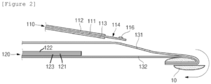
- a positive electrode 120, a negative electrode 110, and separators 131 and 132 provided between the positive electrode 120 and the negative electrode 110 may be stacked.
- the separators may be provided as two separators.
- a first separator 131 may be provided between the negative electrode 110 and the positive electrode 120
- a second separator 132 may be additionally provided on a surface opposite to the surface of the positive electrode 120 that adjoins the first separator 131.
- the second separator 132, the positive electrode 120, the first separator 131, and the negative electrode 110 may be sequentially stacked.
- the second separator 132, the positive electrode 120, the first separator 131, and the negative electrode 110 may be sequentially stacked and wound toward the negative electrode 110 in the winding direction.
- the separator of the wound electrode assembly may be exposed to an outermost periphery 1b.
- the winding process is performed toward the positive electrode 120 in the direction opposite to the winding direction.
- the negative electrode 110 or the negative electrode 110 and the separators 131 and 132 of the wound electrode assembly may be exposed to the outermost periphery 1b.
- the negative electrode in case that the negative electrode is exposed to the outermost periphery 1b, only a negative electrode non-coated portion at an outer peripheral side, on which no negative electrode active material layer is provided, may be exposed, or a negative electrode coated portion at the outer peripheral side, together with the negative electrode non-coated portion at the outer peripheral side, may also be exposed to the outermost periphery 1b.
- An interior 1c of an wound electrode assembly 1 as illustrated in FIG. 1 refers to a portion of the wound electrode assembly that excludes the outermost periphery 1b.
- the outermost periphery 1b means a lateral surface exposed to the outside, and the interior 1c includes an entire inner region of the column that excludes the lateral surface.
- a winding roll having the top plan view illustrated in FIG. 3 may be manufactured by winding the electrode assembly 1 stacked as illustrated in FIG. 2 .
- the positive electrode 120 and the negative electrode 110 may each include a current collector, and an active material layer provided on at least one surface of the current collector.
- the positive electrode 120 may include a positive electrode current collector 121 and positive electrode active material layers 122 and 123 provided on at least one surface of the positive electrode current collector 121.
- the positive electrode active material layers 122 and 123 may be provided on two opposite surfaces of the positive electrode current collector 121 and include a first positive electrode active material layer 122 provided on one surface of the positive electrode current collector 121, and a second positive electrode active material layer 123 provided on a surface opposite to one surface on which the first positive electrode active material layer 122 is provided.
- the positive electrode 120 includes one or more positive electrode tabs, and the positive electrode tab is positioned on a positive electrode non-coated portion on which the positive electrode active material layers 122 and 123 are not provided.
- the positive electrode 120 may include a positive electrode coated portion on which a positive electrode active material layer is provided on the positive electrode current collector 121, and a positive electrode non-coated portion provided at a distal end of one side or two opposite sides of the positive electrode current collector 121 and having no positive electrode active material layer.
- the positive electrode tab may be positioned on the positive electrode non-coated portion positioned at the distal end of one side or two opposite sides of the positive electrode current collector 121, particularly positioned on the positive electrode non-coated portion at the distal end of one side.
- the positive electrode 120 may include a positive electrode non-coated portion provided at an outer peripheral side end of the positive electrode current collector 121 and having no positive electrode active material layer, and the positive electrode tab may be formed on the positive electrode non-coated portion.
- the positive electrode 120 may include two or more positive electrode coated portions provided on the positive electrode current collector 121, having positive electrode active material layers, and spaced apart from one another in a longitudinal direction, and a positive electrode non-coated portion provided between the two or more positive electrode coated portions and having no positive electrode active material layer.
- the positive electrode tab may be positioned on the positive electrode non-coated portion between the two or more positive electrode coated portions, particularly positioned on the positive electrode non-coated portion positioned between the two positive electrode coated portions.
- the distal ends of the two opposite sides of the positive electrode 120 may be formed as free edges having no positive electrode non-coated portion.
- the positive electrode 120 may include the positive electrode current collector 121 and the positive electrode active material layers 122 and 123 provided on two opposite surfaces of the positive electrode current collector 121.
- the first positive electrode active material layer 122 provided on one surface of the positive electrode current collector 121 may be identical or different in length to or from the second positive electrode active material layer 123 provided on the other surface.
- the positive electrode 120 may include the positive electrode current collector 121 and the positive electrode active material layers 122 and 123 provided on the two opposite surfaces of the positive electrode current collector 121, and winding start portions of the positive electrode active material layers 122 and 123 provided on the two opposite surfaces of the positive electrode current collector 121 may be identical to each other.
- the positive electrode 120 may include the positive electrode active material layers 122 and 123 provided on the two opposite surfaces of the positive electrode current collector 121, and winding end portions of the positive electrode active material layers 122 and 123 provided on the two opposite surfaces of the positive electrode current collector 121 may be identical to each other.
- the negative electrode 110 may include a negative electrode current collector 111 and negative electrode active material layers 112 and 113 provided on at least one surface of the negative electrode current collector 111.
- the negative electrode active material layers 112 and 113 may be provided on two opposite surfaces of the negative electrode current collector 111 and include a first negative electrode active material layer 112 provided on one surface of the negative electrode current collector 111, and a second negative electrode active material layer 113 provided on a surface opposite to one surface on which the first negative electrode active material layer 112 is provided.
- the negative electrode 110 includes one or more negative electrode tabs 116, and the negative electrode tabs 116 are positioned on the negative electrode non-coated portions on which the negative electrode active material layers 112 and 113 are not provided.
- the negative electrode 110 may include a negative electrode coated portion on which a negative electrode active material layer is provided on the negative electrode current collector 111, and a negative electrode non-coated portion provided at a distal end of one side or two opposite sides of the negative electrode current collector 111 and having no negative electrode active material layer.
- the negative electrode tab 116 may be positioned on the negative electrode non-coated portion positioned at the distal end of one side or two opposite sides of the negative electrode current collector 111, particularly positioned on the negative electrode non-coated portion at the distal end of the two opposite sides.
- the negative electrode 110 may include a negative electrode non-coated portion positioned at an end of the mandrel part side of the negative electrode current collector 111 and having no active material layer, and the negative electrode tab 116 may be formed on the negative electrode non-coated portion.
- the negative electrode 110 may include the negative electrode current collector 111 and the negative electrode active material layers 112 and 113 provided on two opposite surfaces of the negative electrode current collector 111.
- the first negative electrode active material layer 112 provided on one surface of the negative electrode current collector 111 may be identical or different in length to or from the second negative electrode active material layer 113 provided on the other surface.
- the positive electrode 120 may include: two positive electrode coated portions spaced apart from each other in the winding direction of the electrode assembly 1 and having the positive electrode active material layers 122 and 123 on the positive electrode current collector 121; and a positive electrode non-coated portion provided between the two coated portion and having no positive electrode active material layer on the positive electrode current collector 121.
- One positive electrode tab may be formed on the positive electrode non-coated portion
- the negative electrode 110 may include two negative electrode non-coated portions provided at two opposite ends of the negative electrode current collector 111 and having no negative electrode active material layer.
- the negative electrode tabs 116 may be formed on the two negative electrode non-coated portions, one negative electrode tab for each negative electrode non-coated portion.
- the embodiment of the present specification provides the electrode assembly 1 in which the positive electrode 120, the negative electrode 110, and the separators 131 and 132 provided between the positive electrode 120 and the negative electrode 110 are stacked and wound, the negative electrode 110 includes the negative electrode current collector 111 and the negative electrode active material layers 112 and 113 provided on at least one surface of the negative electrode current collector 111, the negative electrode 110 includes the negative electrode non-coated portion provided at one end of the mandrel part side of the negative electrode current collector 111 and having no negative electrode active material layer, the negative electrode tab 116 is provided on the negative electrode non-coated portion, and the separators 131 and 132 and the negative electrode 110 extend from the mandrel part side of the electrode assembly 1 so as to be further elongated than a longitudinal end of the mandrel part side of the positive electrode 120 and are additionally wound.
- a winding start portion of the positive electrode 120 is a radius.
- the central angle of the minor arc formed from the contact point to the longitudinal end of the positive electrode may be 90° or less, 85° or less, 80° or less, 75° or less, 70° or less, 65° or less, 60° or less, 55° or less, 50° or less, 45° or less, 40° or less, 35° or less, 30° or less, 25° or less, 20° or less, 15° or less, 10° or less, or 5° or less and 0° or more, more than 0°, 1° or more, 2° or more, 3° or more, or 4° or more.
- the winding start portion of the positive electrode 120 may be a winding start portion of the positive electrode coated portion having the positive electrode active material layers 122 and 123.
- the winding start portion may be expressed as a winding start point that is a single point.
- the positive electrode 120 may include the positive electrode current collector 121 and the positive electrode active material layers 122 and 123 provided on at least one surface of the positive electrode current collector 121, the positive electrode 120 may include a positive electrode non-coated portion having no positive electrode active material layer, and a positive electrode tab (not illustrated) may be provided on the positive electrode non-coated portion.
- a central angle b of an arc formed to the longitudinal end of the positive electrode 120 from the contact point at which the line, which extends from the winding start portion of the positive electrode tab (not illustrated) to the arbitrary point on the circumference of the arbitrary circle, is orthogonal to the tangent line to the arbitrary circle, may be more than 90° and 180° or less.
- a mandrel 10 illustrated in FIG. 2 is a winding device, and the mandrel 10 is removed after the winding process is completed as illustrated in FIG. 3 .
- the mandrel 10 may be a space, which is maintained after the winding device is removed, or the mandrel 10 may be a winding reference line.
- the mandrel 10 may be a center point of the circle.
- the term "mandrel part side" means a region close to the mandrel or a direction toward the mandrel.
- Still another embodiment of the present specification provides the electrode assembly 1 in which the positive electrode 120, the negative electrode 110, and the separators 131 and 132 provided between the positive electrode 120 and the negative electrode 110 are stacked and wound, the negative electrode 110 includes the negative electrode current collector 111 and the negative electrode active material layers 112 and 113 provided on at least one surface of the negative electrode current collector 111, and the negative electrode 110 includes the negative electrode tab 116 provided at one end of the mandrel part side of the negative electrode current collector 111.
- the separators 131 and 132 and the negative electrode 110 extend from the mandrel part side of the electrode assembly 1 so as to be further elongated than the longitudinal end of the positive electrode 120 and are additionally wound.
- an angle ⁇ 1 defined between a straight line L ce extending from the mandrel to the longitudinal end of the mandrel part side of the positive electrode 120 and a straight line L at extending from the mandrel to the winding start portion of the negative electrode tab 116 may be 90° or less.
- the angle ⁇ 1 is an angle from the straight line L ce to the straight line L at in a counterclockwise direction, an angle from the straight line L at to the straight line L ce in a clockwise direction, or an angle from the straight line L ce to the straight line L at in the winding direction.
- the angle ⁇ 1 is the central angle a of the minor arc formed to the longitudinal end of the mandrel part side of the positive electrode from the contact point at which the line extending from the winding start portion of the negative electrode tab 116 to the arbitrary point on the circumference of the arbitrary circle is orthogonal to the tangent line to the arbitrary circle.
- the contact point of the winding start portion of the negative electrode tab 116 is present within a range of 90° or less in the winding direction.
- the negative electrode 110 further extends than the positive electrode 120 and is wound around the mandrel, the negative electrode tab 116 at the mandrel side is wound first before the winding start portion of the positive electrode is wound, and then the positive electrode 120 is wound.
- the contact point of the winding start portion of the negative electrode tab 116 is present within the range of 90° or less in the winding direction, such that the negative electrode tab 116 is disposed rearward of the winding start portion of the positive electrode 120 in the winding direction of the positive electrode 120.
- the negative electrode tab 116 which is relatively rigid and wound before the positive electrode 120 is wound, presses an end of the mandrel part side of the positive electrode 120 by using a centrifugal force, which may prevent a movement, i.e., a slip of the end of the mandrel part side of the positive electrode 120.
- a length of the negative electrode tab 116 may be 2 mm or more and 5 mm or less in the winding direction.
- the rigidity is imparted to suppress the motion of the mandrel part side of the positive electrode 120 by pressing the end of the mandrel part side of the positive electrode 120.
- the negative electrode 110 may further include an additional negative electrode non-coated portion provided at one end of the outer peripheral side of the negative electrode current collector 111 and having no negative electrode active material layer, and an additional negative electrode tab may be provided on the additional negative electrode non-coated portion.
- an angle ⁇ 2 defined between a straight line L ce extending from the mandrel to the longitudinal end of the mandrel part side of the positive electrode 120 and a straight line L ae extending from the mandrel to the winding start portion of the positive electrode tab may be more than 90° and 180° or less.
- the angle ⁇ 2 is an angle from the straight line L ce to the straight line L ae in the counterclockwise direction, an angle from the straight line L ae to the straight line L ce in the clockwise direction, or an angle from the straight line L ce to the straight line L ae in the winding direction.
- angle ⁇ 2 may be the central angle b of the minor arc formed to the longitudinal end of the mandrel part side of the positive electrode 120 from the contact point at which the line extending from the winding start portion of the positive electrode tab (not illustrated) to the arbitrary point on the circumference of the arbitrary circle is orthogonal to the tangent line to the arbitrary circle.
- the longitudinal end (winding start portion) of the mandrel part side of the positive electrode 120 may be expressed as a 6 o'clock position
- the winding start portion of the negative electrode tab 116 may be expressed as a 4 o'clock position
- the winding start portion of the positive electrode tab (not illustrated) may be expressed as a 12 o'clock position.
- Yet another embodiment of the present specification provides a secondary battery including the electrode assembly and a battery case configured to accommodate the electrode assembly.
- a cross-section of the electrode assembly perpendicular to the mandrel axis may be a circle, and the battery case may have a cylindrical shape.
- the secondary battery may be a battery having a ratio of a form factor that is about 0.4 or less (the ratio of the form factor is defined as a value made by dividing a diameter of the cylindrical battery by a height of the cylindrical battery, i.e., a ratio of a diameter ⁇ to a height H).
- the form factor means a value indicating the diameter and the height of the cylindrical secondary battery.
- 18650 cell, 21700 cell, and the like may be used.
- a diameter thereof is approximately 18 mm
- a height thereof is approximately 65 mm
- a ratio of the form factor thereof is approximately 0.277.
- a diameter thereof is approximately 21 mm
- a height thereof is approximately 70 mm
- a ratio of the form factor thereof is approximately 0.300.
- the secondary battery may be a cylindrical secondary battery having a ratio of the form factor that is larger than 0.4.
- the cylindrical secondary battery according to the embodiment of the present specification may be 46110 cell, 48750 cell, 48110 cell, 48800 cell, or 46800 cell.
- the first two numbers indicate a diameter of the cell
- the next two numbers indicate a height of the cell
- the final number 0 indicates that a cross-section of the cell is circular.
- the secondary battery according to the embodiment of the present specification may be a cylindrical secondary battery that is a cylindrical cell and has a diameter of 46 mm, a height of 110 mm, and a ratio of the form factor of 0.418.
- the secondary battery according to the embodiment of the present specification may be a cylindrical secondary battery that is a cylindrical cell and has a diameter of 48 mm, a height of 75 mm, and a ratio of the form factor of 0.640.
- the secondary battery according to the embodiment of the present specification may be a cylindrical secondary battery that is a cylindrical cell and has a diameter of 48 mm, a height of 110 mm, and a ratio of the form factor of 0.436.
- the secondary battery according to the embodiment of the present specification may be a cylindrical secondary battery that is a cylindrical cell and has a diameter of 48 mm, a height of 80 mm, and a ratio of the form factor of 0.600.
- the secondary battery according to the embodiment of the present specification may be a cylindrical secondary battery that is a cylindrical cell and has a diameter of 46 mm, a height of 80 mm, and a ratio of the form factor of 0.575.
- Another embodiment of the present specification provides the secondary battery including the electrode assembly 1 and the battery case configured to accommodate the electrode assembly 1.
- FIG. 4 illustrates a secondary battery 20 in which the wound electrode assembly 1 is accommodated in the battery case.
- a cross-section of the electrode assembly 1 perpendicular to the mandrel axis may be a circle, and the battery case may have a cylindrical shape.
- the battery case may include a can 21 and a cap assembly 22.
- the can 21 may have a column structure having a space therein.
- the internal space of the can 21 may accommodate an electrolyte (not illustrated) and the battery assembly 1 including the electrode and the separator.
- the can 21 may have one side having an opened structure, and the other side having a sealed structure. In this case, one side and the other side of the can 21 may mean ends positioned on the upper and lower portions in the gravitational direction or along the central axis of the can 21.
- the can 21 may be made of a lightweight conductive metallic material such as aluminum or aluminum alloy.
- the cap assembly 22 may be coupled to an upper portion of the can 21 and include a top cap, a safety vent, and a current blocking element.
- the top cap may protrude from an uppermost portion of the cap assembly 22 and serve as an electrode terminal electrically connected to an external component.
- the safety vent may discharge a high-pressure gas when the gas is generated at a predetermined level or higher because of an increase in internal pressure.
- the current blocking element may block an electric current when the internal pressure of the battery increases.
- the top cap may be coupled to the upper portion of the can 21. That is, the top cap may be coupled to a crimping portion positioned on an uppermost portion of the can 21.
- the secondary battery 20 according to the present invention may include a gasket between the crimping portion and the top cap.
- the gasket may increase sealability of the case.
- the top cap may include a protruding portion protruding upward in the gravitational direction, a rim portion coupled to the gasket, and a connection portion configured to connect the protruding portion and the rim portion.
- the safety vent may be positioned below the top cap and coupled to an end of the top cap.
- the safety vent is in contact with an end of the top cap by a predetermined length, and a portion, except for a contact length, may be positioned to be spaced apart from the top cap at a predetermined distance.
- the safety vent may be bent one or more times. For example, two notches may be provided on a portion of the safety vent that is not in contact with the top cap. That is, the safety vent may be bent by a notch, and a center of the safety vent may be recessed to define a recessed central portion. Further, the safety vent may have a venting portion that connects the recessed central portion and the end being in contact with the top cap.
- the current blocking element may be positioned below the safety vent and be at least partially in contact with the safety vent.
- the current blocking element may include a central portion protruding in a direction toward the safety vent, and a CID filter portion positioned outside the central portion. Therefore, a central portion of the current blocking element of the cap assembly 22 may be in contact with the recessed central portion of the safety vent.
- the cap assembly 22 may have a CID gasket provided at an end of the CID filter portion.
- the CID gasket may prevent the safety vent from being in contact with a portion except for the central portion of the current blocking element.
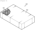
- FIG. 5 is a view schematically illustrating a configuration of the battery pack according to the embodiment of the present invention.
- a battery pack 200 includes an assembly to which a secondary battery cell 201 is electrically connected, and a pack housing 202 configured to accommodate the assembly.
- the cylindrical secondary battery cell 201 is the battery cell according to the above-mentioned embodiment.
- components such as busbars for electrical connection between the cylindrical battery cells 201, a cooling unit, and an external terminal are omitted from the drawings.
- Still another embodiment of the present specification provides a transportation means including the battery pack 200.
- the transportation means may mean any means that works while moving or moving goods, people, and the like.
- the transportation means may be a bicycle, heavy equipment, agricultural equipment, vehicle, bus, airplane, or the like.
- the battery pack 200 may be mounted in a vehicle V.
- the vehicle may be an electric vehicle, a hybrid vehicle, or a plug-in hybrid vehicle.
- the vehicle V may be a four-wheel vehicle or a two-wheel vehicle.
- FIG. 6 is a view for explaining the vehicle V including the battery pack 200 illustrated in FIG. 5 .
- the vehicle V includes the battery pack 200 according to the embodiment of the present specification.
- the vehicle V operates by receiving electric power from the battery pack 200 according to the embodiment of the present invention.
- a jelly-roll (J/R) with a cross-sectional diameter of 20.5 mm was manufactured by stacking a negative electrode, a positive electrode, and two separators and winding an electrode assembly so that the arrangement was as illustrated in FIG. 8B before an operation.
- a thickness of the positive electrode current collector is about 0.015 mm
- an overall thickness of the positive electrode coated portions provided on the two opposite surfaces of the positive electrode current collector and having the positive electrode active material layer is about 0.150 mm.
- a thickness of the negative electrode current collector is about 0.008 mm
- an overall thickness of the negative electrode coated portions provided on the two opposite surfaces of the negative electrode current collector and having the negative electrode active material layer is about 0.180 mm.
- the term "before an operation" in FIG. 8 is a CT image showing an initial arrangement state, the separator is not shown, a relatively thick line is the positive electrode, and the thin line is a negative electrode.
- the negative electrode coated portion and the positive electrode coated portion have the equal or similar thicknesses. Because the carbon-based active material of the negative electrode coated portion transmits light, the negative electrode active material layer is not visible in the CT image, and only the negative electrode current collector is visible in the CT image and shown to be relatively thin.
- the jelly-roll type assembly was inserted into the can (cross-sectional diameter: 21 mm) having the cylindrical shape.
- the battery of the example was completely manufactured by injecting a carbonate-based electrolyte into the can and sealing the can.
- a jelly-roll (J/R) with a cross-sectional diameter of 20.5 mm was manufactured by stacking a negative electrode, a positive electrode, and two separators and winding an electrode assembly so that the arrangement was as illustrated in FIG. 8A before an operation. Thereafter, as in the embodiment, the battery was completely manufactured by inserting the electrode assembly into the case and injecting the electrolyte.
- the position of the winding start portion of the positive electrode was adjusted based on the stack of the comparative example to implement the same arrangement as before the operation in FIG. 8B , i.e., the winding start portion of the positive electrode was changed to be closer to the negative electrode tab.
- the changed position of the winding start portion of the positive electrode was determined in consideration of the size of the mandrel 10, a target diameter of the wound jelly-roll, and a diameter of the battery case. Specifically, as illustrated in FIG.
- a deformation degree of the mandrel side negative electrode in the vicinity of the positive electrode winding start portion may be identified from a deformed angle with respect to the reference line, and the measured deformation degrees are shown in Table 1 below.
- Table 1 Example Comparative Example Deformation Degree (°) 15.9 33.9
- the mandrel side of the battery of the comparative example is deformed by the expansion of the electrode during the charging or discharging process, but in the example in which the negative electrode tab is disposed rearward of the winding start portion of the positive electrode in the winding direction of the positive electrode, the movement of the mandrel side of the battery is suppressed, such that the deformation, which may cause an internal short circuit, is reduced by 53% ((33.9-15.9) ⁇ 100/33.9).
Landscapes
- Chemical & Material Sciences (AREA)
- Chemical Kinetics & Catalysis (AREA)
- Electrochemistry (AREA)
- General Chemical & Material Sciences (AREA)
- Engineering & Computer Science (AREA)
- Manufacturing & Machinery (AREA)
- Composite Materials (AREA)
- Secondary Cells (AREA)
- Connection Of Batteries Or Terminals (AREA)
Abstract
Description
- This application claims priority to and the benefit of
Korean Patent Application No. 10-2022-0184812 filed with the Korean Intellectual Property Office on December 26, 2022 - The present specification relates to an electrode assembly, in which a positive electrode, a negative electrode, and a separator provided between the positive electrode and the negative electrode are stacked and wound, a secondary battery including the same, a battery pack, and a transportation means.
- In the case of a cylindrical battery, a jelly-roll type electrode assembly is manufactured by winding a long electrode, which is a predetermined width, in the form of a roll. The electrodes of the cylindrical battery, which is manufactured by inserting the jelly-roll type electrode assembly into a battery casing, are repeatedly contracted and expanded during a charging or discharging process. In particular, in case that tabs are positioned in a core of the jelly-roll type electrode assembly or a silicon-based active material is added into the negative electrode and a degree to which the electrode assembly is contracted or expanded is increased, a pressure applied to a mandrel of the electrode assembly is greatly increased.
- Recently, with the increase in use of low-resistance/high-capacity designs, there has been an increasing number of cases in which the jelly-roll type electrode assembly includes the plurality of tabs or the silicon-based active material is added. Therefore, there is an increasing likelihood that the electrode assembly positioned at the mandrel side is deformed by the contraction or expansion of the electrode assembly. In particular, in case that a separator positioned between a negative electrode and a positive electrode is damaged, the negative electrode and the positive electrode come into direct contact with each other, which causes an internal short circuit that leads to a problem of heat generation and ignition.
- In order to prevent the problem of the occurrence of damage to the separator and the internal short circuit caused by the deformation of the electrode assembly, there is a need to develop a technology capable of protecting the positive electrode and the separator in the corresponding region and suppressing the occurrence of the internal short circuit.
- The present specification has been made in an effort to provide an electrode assembly, in which a positive electrode, a negative electrode, and a separator provided between the positive electrode and the negative electrode are stacked and wound, a secondary battery including the same, a battery pack, and a transportation means.
- An embodiment of the present specification provides an electrode assembly in which a positive electrode, a negative electrode, and separators provided between the positive electrode and the negative electrode are stacked and wound, in which the negative electrode includes a negative electrode current collector and a negative electrode active material layer provided on at least one surface of the negative electrode current collector, in which the negative electrode includes a negative electrode non-coated portion provided at one end of a mandrel part side of the negative electrode current collector and having no negative electrode active material layer, in which a negative electrode tab is provided on the negative electrode non-coated portion, in which the separator and the negative electrode extend toward a mandrel part side of the electrode assembly so as to be further elongated than a longitudinal end of the positive electrode and are additionally wound, and in which on an arbitrary circle in which a mandrel of the electrode assembly is a center of the circle and a distance from the center of the circle to the longitudinal end of the positive electrode is a radius, a central angle of a minor arc formed to the longitudinal end of the positive electrode from a contact point at which a line extending from a winding start portion of the negative electrode tab to an arbitrary point on a circumference of the arbitrary circle is orthogonal to a tangent line to the arbitrary circle is 90° or less. Specifically, the central angle of the minor arc formed from the contact point to the longitudinal end of the positive electrode may be 90° or less, 85° or less, 80° or less, 75° or less, 70° or less, 65° or less, 60° or less, 55° or less, 50° or less, 45° or less, 40° or less, 35° or less, 30° or less, 25° or less, 20° or less, 15° or less, 10° or less, or 5° or less and 0° or more, more than 0°, 1° or more, 2° or more, 3° or more, or 4° or more.
- In another embodiment of the present specification, the positive electrode may include the positive electrode current collector and the positive electrode active material layers provided on at least one surface of the positive electrode current collector, the positive electrode may include a positive electrode non-coated portion having no positive electrode active material layer, and a positive electrode tab may be provided on the positive electrode non-coated portion. In this case, on the arbitrary circle, a central angle of an arc formed to the longitudinal end of the positive electrode from the contact point at which the line, which extends from the winding start portion of the positive electrode tab to the arbitrary point on the circumference of the arbitrary circle, is orthogonal to the tangent line to the arbitrary circle, may be more than 90° and 180° or less.
- In another embodiment of the present specification, the positive electrode non-coated portion may be positioned between two positive electrode coated portions having the positive electrode active material layers.
- In another embodiment of the present specification, the negative electrode may further include an additional negative electrode non-coated portion provided at one end of the outer peripheral side of the negative electrode current collector and having no negative electrode active material layer, and an additional negative electrode tab may be provided on the additional negative electrode non-coated portion.
- In another embodiment of the present specification, the positive electrode may include a positive electrode current collector and positive electrode active material layers provided on two opposite surfaces of the positive electrode current collector, and winding start portions of the positive electrode active material layers provided on the two opposite surfaces of the positive electrode current collector are identical to or different from each other, particularly identical to each other.
- In another embodiment of the present specification, the positive electrode may include positive electrode active material layers provided on two opposite surfaces of the positive electrode current collector, and winding end portions of the positive electrode active material layers provided on the two opposite surfaces of the positive electrode current collector may be identical to or different from each other, and particularly identical to each other.
- In another embodiment of the present specification, a length of the negative electrode tab may be 2 mm or more and 5 mm or less in the winding direction.
- In another embodiment of the present specification, the separators may include a first separator and a second separator, and the electrode assembly may be made by sequentially stacking and winding the negative electrode, the first separator, the positive electrode, and the second separator.
- In another embodiment of the present specification, the electrode assembly may be wound so that the negative electrode is disposed on an outermost periphery.
- Yet another embodiment of the present specification provides a secondary battery including the electrode assembly and a battery case configured to accommodate the electrode assembly. In addition, a cross-section of the electrode assembly perpendicular to the mandrel axis may be a circle, and the battery case may have a cylindrical shape.
- Another embodiment of the present specification provides a battery pack including two or more secondary batteries.
- Still another embodiment of the present specification provides a transportation means including the battery pack. The transportation means may mean any means that works while moving or moving goods, people, and the like. The transportation means may be a bicycle, heavy equipment, agricultural equipment, vehicle, bus, airplane, or the like.
- According to the electrode assembly according to the embodiment of the present specification, the negative electrode tab is disposed rearward of the winding start portion of the positive electrode in the winding direction of the positive electrode, which may suppress a slip of the end of the positive electrode during the process of charging or discharging the battery.
- The electrode assembly according to another embodiment of the present specification may be provided to prevent damage to the separator caused by the deformation of the electrode assembly caused by the contraction/expansion of the electrode during the process of charging or discharging the battery and prevent an internal short circuit between the electrodes, which may improve the stability and lifespan properties of the battery.
- According to the electrode assembly according to still another embodiment of the present specification, the negative electrode tab is disposed rearward of the winding start portion of the positive electrode in the winding direction of the positive electrode, which may properly maintain the shape of the mandrel part during the process of charging or discharging the battery.
-
-
FIG. 1 is a perspective view of a wound electrode stack. -
FIG. 2 is a view illustrating a process of winding the electrode stack. -
FIG. 3 is a top plan view illustrating the wound electrode stack and illustrating an arbitrary circle having a radius that is a distance from a center of the circle to a longitudinal end of the positive electrode based on the top plan view. -
FIG. 4 is a vertical cross-sectional view of a secondary battery accommodated in a battery casing in which the wound electrode stack is accommodated. -
FIG. 5 is a view schematically illustrating a configuration of a battery pack according to an embodiment of the present invention. -
FIG. 6 is a view for explaining a vehicle including the battery pack inFIG. 5 . -
FIG. 7 is a view illustrating the determination of a position of a positive electrode winding start portion in the embodiment. -
FIG. 8 is a view illustrating CT images made before and after operations of batteries according to an example and a comparative example. -
FIG. 9 is a view illustrating a method of identifying, from the CT images, a degree of deformation of a mandrel side negative electrode after the operation of the battery. -
- 1: Electrode assembly
- 10: Mandrel
- 1b: Outermost periphery
- 1c: Interior
- 110: Negative electrode
- 111: Negative electrode current collector
- 112: First negative electrode active material layer
- 113: Second negative electrode active material layer
- 114: Negative electrode non-coated portion
- 116: Negative electrode tab
- 120: Positive electrode
- 121: Positive electrode current collector
- 122: First positive electrode active material layer
- 123: Second positive electrode active material layer
- 131: First separator
- 132: Second separator
- 20: Secondary battery
- 21: Can
- 22: Cap assembly
- 200: Battery pack
- 201: Cylindrical battery cell
- 202: Pack housing
- V: Vehicle
- Hereinafter, the present invention will be described in detail with reference to the drawings. However, the drawings are intended to illustratively describe the present invention, and the scope of the present invention is not limited by the drawings.
-
FIG. 1 is a perspective view of a wound electrode stack. First, apositive electrode 120, anegative electrode 110, andseparators positive electrode 120 and thenegative electrode 110 may be stacked. The separators may be provided as two separators. As illustrated inFIG. 1 , afirst separator 131 may be provided between thenegative electrode 110 and thepositive electrode 120, and asecond separator 132 may be additionally provided on a surface opposite to the surface of thepositive electrode 120 that adjoins thefirst separator 131. Specifically, thesecond separator 132, thepositive electrode 120, thefirst separator 131, and thenegative electrode 110 may be sequentially stacked. - The
second separator 132, thepositive electrode 120, thefirst separator 131, and thenegative electrode 110 may be sequentially stacked and wound toward thenegative electrode 110 in the winding direction. In case that the winding process is performed as described above, the separator of the wound electrode assembly may be exposed to anoutermost periphery 1b. - As necessary, as illustrated in
FIG. 2 , the winding process is performed toward thepositive electrode 120 in the direction opposite to the winding direction. In case that the winding process is performed as described above, thenegative electrode 110 or thenegative electrode 110 and theseparators outermost periphery 1b. In this case, in case that the negative electrode is exposed to theoutermost periphery 1b, only a negative electrode non-coated portion at an outer peripheral side, on which no negative electrode active material layer is provided, may be exposed, or a negative electrode coated portion at the outer peripheral side, together with the negative electrode non-coated portion at the outer peripheral side, may also be exposed to theoutermost periphery 1b. - An interior 1c of an
wound electrode assembly 1 as illustrated inFIG. 1 refers to a portion of the wound electrode assembly that excludes theoutermost periphery 1b. In this case, when it is assumed that the wound electrode assembly is a column, theoutermost periphery 1b means a lateral surface exposed to the outside, and theinterior 1c includes an entire inner region of the column that excludes the lateral surface. - A winding roll having the top plan view illustrated in
FIG. 3 may be manufactured by winding theelectrode assembly 1 stacked as illustrated inFIG. 2 . - The
positive electrode 120 and thenegative electrode 110 may each include a current collector, and an active material layer provided on at least one surface of the current collector. - The
positive electrode 120 may include a positive electrodecurrent collector 121 and positive electrode active material layers 122 and 123 provided on at least one surface of the positive electrodecurrent collector 121. The positive electrode active material layers 122 and 123 may be provided on two opposite surfaces of the positive electrodecurrent collector 121 and include a first positive electrodeactive material layer 122 provided on one surface of the positive electrodecurrent collector 121, and a second positive electrodeactive material layer 123 provided on a surface opposite to one surface on which the first positive electrodeactive material layer 122 is provided. - The
positive electrode 120 includes one or more positive electrode tabs, and the positive electrode tab is positioned on a positive electrode non-coated portion on which the positive electrode active material layers 122 and 123 are not provided. - In the embodiment, the
positive electrode 120 may include a positive electrode coated portion on which a positive electrode active material layer is provided on the positive electrodecurrent collector 121, and a positive electrode non-coated portion provided at a distal end of one side or two opposite sides of the positive electrodecurrent collector 121 and having no positive electrode active material layer. In this case, the positive electrode tab may be positioned on the positive electrode non-coated portion positioned at the distal end of one side or two opposite sides of the positive electrodecurrent collector 121, particularly positioned on the positive electrode non-coated portion at the distal end of one side. - In another embodiment, the
positive electrode 120 may include a positive electrode non-coated portion provided at an outer peripheral side end of the positive electrodecurrent collector 121 and having no positive electrode active material layer, and the positive electrode tab may be formed on the positive electrode non-coated portion. - In another embodiment, the
positive electrode 120 may include two or more positive electrode coated portions provided on the positive electrodecurrent collector 121, having positive electrode active material layers, and spaced apart from one another in a longitudinal direction, and a positive electrode non-coated portion provided between the two or more positive electrode coated portions and having no positive electrode active material layer. In this case, the positive electrode tab may be positioned on the positive electrode non-coated portion between the two or more positive electrode coated portions, particularly positioned on the positive electrode non-coated portion positioned between the two positive electrode coated portions. In this case, the distal ends of the two opposite sides of thepositive electrode 120 may be formed as free edges having no positive electrode non-coated portion. - The
positive electrode 120 may include the positive electrodecurrent collector 121 and the positive electrode active material layers 122 and 123 provided on two opposite surfaces of the positive electrodecurrent collector 121. The first positive electrodeactive material layer 122 provided on one surface of the positive electrodecurrent collector 121 may be identical or different in length to or from the second positive electrodeactive material layer 123 provided on the other surface. - In another embodiment of the present specification, the
positive electrode 120 may include the positive electrodecurrent collector 121 and the positive electrode active material layers 122 and 123 provided on the two opposite surfaces of the positive electrodecurrent collector 121, and winding start portions of the positive electrode active material layers 122 and 123 provided on the two opposite surfaces of the positive electrodecurrent collector 121 may be identical to each other. - In another embodiment of the present specification, the
positive electrode 120 may include the positive electrode active material layers 122 and 123 provided on the two opposite surfaces of the positive electrodecurrent collector 121, and winding end portions of the positive electrode active material layers 122 and 123 provided on the two opposite surfaces of the positive electrodecurrent collector 121 may be identical to each other. - The
negative electrode 110 may include a negative electrodecurrent collector 111 and negative electrode active material layers 112 and 113 provided on at least one surface of the negative electrodecurrent collector 111. The negative electrode active material layers 112 and 113 may be provided on two opposite surfaces of the negative electrodecurrent collector 111 and include a first negative electrodeactive material layer 112 provided on one surface of the negative electrodecurrent collector 111, and a second negative electrodeactive material layer 113 provided on a surface opposite to one surface on which the first negative electrodeactive material layer 112 is provided. - The
negative electrode 110 includes one or morenegative electrode tabs 116, and thenegative electrode tabs 116 are positioned on the negative electrode non-coated portions on which the negative electrode active material layers 112 and 113 are not provided. - In the embodiment, the
negative electrode 110 may include a negative electrode coated portion on which a negative electrode active material layer is provided on the negative electrodecurrent collector 111, and a negative electrode non-coated portion provided at a distal end of one side or two opposite sides of the negative electrodecurrent collector 111 and having no negative electrode active material layer. In this case, thenegative electrode tab 116 may be positioned on the negative electrode non-coated portion positioned at the distal end of one side or two opposite sides of the negative electrodecurrent collector 111, particularly positioned on the negative electrode non-coated portion at the distal end of the two opposite sides. - In another embodiment, the
negative electrode 110 may include a negative electrode non-coated portion positioned at an end of the mandrel part side of the negative electrodecurrent collector 111 and having no active material layer, and thenegative electrode tab 116 may be formed on the negative electrode non-coated portion. - The
negative electrode 110 may include the negative electrodecurrent collector 111 and the negative electrode active material layers 112 and 113 provided on two opposite surfaces of the negative electrodecurrent collector 111. The first negative electrodeactive material layer 112 provided on one surface of the negative electrodecurrent collector 111 may be identical or different in length to or from the second negative electrodeactive material layer 113 provided on the other surface. - In still another embodiment, the
positive electrode 120 may include: two positive electrode coated portions spaced apart from each other in the winding direction of theelectrode assembly 1 and having the positive electrode active material layers 122 and 123 on the positive electrodecurrent collector 121; and a positive electrode non-coated portion provided between the two coated portion and having no positive electrode active material layer on the positive electrodecurrent collector 121. One positive electrode tab may be formed on the positive electrode non-coated portion, and thenegative electrode 110 may include two negative electrode non-coated portions provided at two opposite ends of the negative electrodecurrent collector 111 and having no negative electrode active material layer. Thenegative electrode tabs 116 may be formed on the two negative electrode non-coated portions, one negative electrode tab for each negative electrode non-coated portion. - The embodiment of the present specification provides the
electrode assembly 1 in which thepositive electrode 120, thenegative electrode 110, and theseparators positive electrode 120 and thenegative electrode 110 are stacked and wound, thenegative electrode 110 includes the negative electrodecurrent collector 111 and the negative electrode active material layers 112 and 113 provided on at least one surface of the negative electrodecurrent collector 111, thenegative electrode 110 includes the negative electrode non-coated portion provided at one end of the mandrel part side of the negative electrodecurrent collector 111 and having no negative electrode active material layer, thenegative electrode tab 116 is provided on the negative electrode non-coated portion, and theseparators negative electrode 110 extend from the mandrel part side of theelectrode assembly 1 so as to be further elongated than a longitudinal end of the mandrel part side of thepositive electrode 120 and are additionally wound. In an arbitrary circle in which the mandrel of theelectrode assembly 1 is a center of a circle, and a distance from the center of the circle to the longitudinal end of the mandrel part side of thepositive electrode 120, i.e., a winding start portion of thepositive electrode 120 is a radius. A central angle a of a minor arc formed to the longitudinal end of thepositive electrode 120 from a contact point at which a line, which extends from the winding start portion of thenegative electrode tab 116 to an arbitrary point on a circumference of the arbitrary circle, is orthogonal to a tangent line to the arbitrary circle, is 90° or less. Specifically, the central angle of the minor arc formed from the contact point to the longitudinal end of the positive electrode may be 90° or less, 85° or less, 80° or less, 75° or less, 70° or less, 65° or less, 60° or less, 55° or less, 50° or less, 45° or less, 40° or less, 35° or less, 30° or less, 25° or less, 20° or less, 15° or less, 10° or less, or 5° or less and 0° or more, more than 0°, 1° or more, 2° or more, 3° or more, or 4° or more. In this case, the winding start portion of thepositive electrode 120 may be a winding start portion of the positive electrode coated portion having the positive electrode active material layers 122 and 123. - In the present specification, the winding start portion may be expressed as a winding start point that is a single point.
- In another embodiment of the present specification, the
positive electrode 120 may include the positive electrodecurrent collector 121 and the positive electrode active material layers 122 and 123 provided on at least one surface of the positive electrodecurrent collector 121, thepositive electrode 120 may include a positive electrode non-coated portion having no positive electrode active material layer, and a positive electrode tab (not illustrated) may be provided on the positive electrode non-coated portion. In this case, on the arbitrary circle, a central angle b of an arc formed to the longitudinal end of thepositive electrode 120 from the contact point at which the line, which extends from the winding start portion of the positive electrode tab (not illustrated) to the arbitrary point on the circumference of the arbitrary circle, is orthogonal to the tangent line to the arbitrary circle, may be more than 90° and 180° or less. - In the present specification, a
mandrel 10 illustrated inFIG. 2 is a winding device, and themandrel 10 is removed after the winding process is completed as illustrated inFIG. 3 . InFIG. 3 , themandrel 10 may be a space, which is maintained after the winding device is removed, or themandrel 10 may be a winding reference line. Alternatively, when a perpendicular cross-section of thewound electrode assembly 1, which is taken in a direction perpendicular to an axis of thewound electrode assembly 1, defines a circle, themandrel 10 may be a center point of the circle. The term "mandrel part side" means a region close to the mandrel or a direction toward the mandrel. - Still another embodiment of the present specification provides the
electrode assembly 1 in which thepositive electrode 120, thenegative electrode 110, and theseparators positive electrode 120 and thenegative electrode 110 are stacked and wound, thenegative electrode 110 includes the negative electrodecurrent collector 111 and the negative electrode active material layers 112 and 113 provided on at least one surface of the negative electrodecurrent collector 111, and thenegative electrode 110 includes thenegative electrode tab 116 provided at one end of the mandrel part side of the negative electrodecurrent collector 111. Theseparators negative electrode 110 extend from the mandrel part side of theelectrode assembly 1 so as to be further elongated than the longitudinal end of thepositive electrode 120 and are additionally wound. On at least one cross-section in the direction perpendicular to the mandrel of theelectrode assembly 1, an angle θ1 defined between a straight line Lce extending from the mandrel to the longitudinal end of the mandrel part side of thepositive electrode 120 and a straight line Lat extending from the mandrel to the winding start portion of thenegative electrode tab 116 may be 90° or less. In this case, the angle θ1 is an angle from the straight line Lce to the straight line Lat in a counterclockwise direction, an angle from the straight line Lat to the straight line Lce in a clockwise direction, or an angle from the straight line Lce to the straight line Lat in the winding direction. - In other words, in
FIG. 3 , the angle θ1 is the central angle a of the minor arc formed to the longitudinal end of the mandrel part side of the positive electrode from the contact point at which the line extending from the winding start portion of thenegative electrode tab 116 to the arbitrary point on the circumference of the arbitrary circle is orthogonal to the tangent line to the arbitrary circle. On the arbitrary circle, based on the longitudinal end of the mandrel part side of the positive electrode, the contact point of the winding start portion of thenegative electrode tab 116 is present within a range of 90° or less in the winding direction. - Because the
negative electrode 110 further extends than thepositive electrode 120 and is wound around the mandrel, thenegative electrode tab 116 at the mandrel side is wound first before the winding start portion of the positive electrode is wound, and then thepositive electrode 120 is wound. As illustrated inFIG. 3 , on the arbitrary circle, based on the longitudinal end of the mandrel part side of thepositive electrode 120, the contact point of the winding start portion of thenegative electrode tab 116 is present within the range of 90° or less in the winding direction, such that thenegative electrode tab 116 is disposed rearward of the winding start portion of thepositive electrode 120 in the winding direction of thepositive electrode 120. In this case, thenegative electrode tab 116, which is relatively rigid and wound before thepositive electrode 120 is wound, presses an end of the mandrel part side of thepositive electrode 120 by using a centrifugal force, which may prevent a movement, i.e., a slip of the end of the mandrel part side of thepositive electrode 120. - In another embodiment of the present specification, a length of the
negative electrode tab 116 may be 2 mm or more and 5 mm or less in the winding direction. In this case, the rigidity is imparted to suppress the motion of the mandrel part side of thepositive electrode 120 by pressing the end of the mandrel part side of thepositive electrode 120. - In another embodiment of the present specification, the
negative electrode 110 may further include an additional negative electrode non-coated portion provided at one end of the outer peripheral side of the negative electrodecurrent collector 111 and having no negative electrode active material layer, and an additional negative electrode tab may be provided on the additional negative electrode non-coated portion. - In another embodiment of the present specification, an angle θ2 defined between a straight line Lce extending from the mandrel to the longitudinal end of the mandrel part side of the
positive electrode 120 and a straight line Lae extending from the mandrel to the winding start portion of the positive electrode tab (not illustrated) may be more than 90° and 180° or less. In this case, the angle θ2 is an angle from the straight line Lce to the straight line Lae in the counterclockwise direction, an angle from the straight line Lae to the straight line Lce in the clockwise direction, or an angle from the straight line Lce to the straight line Lae in the winding direction. In addition, the angle θ2 may be the central angle b of the minor arc formed to the longitudinal end of the mandrel part side of thepositive electrode 120 from the contact point at which the line extending from the winding start portion of the positive electrode tab (not illustrated) to the arbitrary point on the circumference of the arbitrary circle is orthogonal to the tangent line to the arbitrary circle. - As illustrated in
FIG. 3 , when the positions in the arbitrary circle are expressed by using positions on a clock, the longitudinal end (winding start portion) of the mandrel part side of thepositive electrode 120 may be expressed as a 6 o'clock position, the winding start portion of thenegative electrode tab 116 may be expressed as a 4 o'clock position, and the winding start portion of the positive electrode tab (not illustrated) may be expressed as a 12 o'clock position. - Yet another embodiment of the present specification provides a secondary battery including the electrode assembly and a battery case configured to accommodate the electrode assembly. In addition, a cross-section of the electrode assembly perpendicular to the mandrel axis may be a circle, and the battery case may have a cylindrical shape.
- In the embodiment of the present specification, the secondary battery may be a battery having a ratio of a form factor that is about 0.4 or less (the ratio of the form factor is defined as a value made by dividing a diameter of the cylindrical battery by a height of the cylindrical battery, i.e., a ratio of a diameter Φ to a height H). In this case, the form factor means a value indicating the diameter and the height of the cylindrical secondary battery. For example, 18650 cell, 21700 cell, and the like may be used. In the case of 18650 cell, a diameter thereof is approximately 18 mm, a height thereof is approximately 65 mm, and a ratio of the form factor thereof is approximately 0.277. In the case of 21700 cell, a diameter thereof is approximately 21 mm, a height thereof is approximately 70 mm, and a ratio of the form factor thereof is approximately 0.300.
- In the embodiment of the present specification, the secondary battery may be a cylindrical secondary battery having a ratio of the form factor that is larger than 0.4.
- The cylindrical secondary battery according to the embodiment of the present specification may be 46110 cell, 48750 cell, 48110 cell, 48800 cell, or 46800 cell. In the numerical value indicating the form factor, the first two numbers indicate a diameter of the cell, the next two numbers indicate a height of the cell, and the final number 0 indicates that a cross-section of the cell is circular.
- The secondary battery according to the embodiment of the present specification may be a cylindrical secondary battery that is a cylindrical cell and has a diameter of 46 mm, a height of 110 mm, and a ratio of the form factor of 0.418.
- The secondary battery according to the embodiment of the present specification may be a cylindrical secondary battery that is a cylindrical cell and has a diameter of 48 mm, a height of 75 mm, and a ratio of the form factor of 0.640.
- The secondary battery according to the embodiment of the present specification may be a cylindrical secondary battery that is a cylindrical cell and has a diameter of 48 mm, a height of 110 mm, and a ratio of the form factor of 0.436.
- The secondary battery according to the embodiment of the present specification may be a cylindrical secondary battery that is a cylindrical cell and has a diameter of 48 mm, a height of 80 mm, and a ratio of the form factor of 0.600.
- The secondary battery according to the embodiment of the present specification may be a cylindrical secondary battery that is a cylindrical cell and has a diameter of 46 mm, a height of 80 mm, and a ratio of the form factor of 0.575.
- Another embodiment of the present specification provides the secondary battery including the
electrode assembly 1 and the battery case configured to accommodate theelectrode assembly 1. -
FIG. 4 illustrates asecondary battery 20 in which thewound electrode assembly 1 is accommodated in the battery case. A cross-section of theelectrode assembly 1 perpendicular to the mandrel axis may be a circle, and the battery case may have a cylindrical shape. The battery case may include acan 21 and acap assembly 22. - The
can 21 may have a column structure having a space therein. The internal space of thecan 21 may accommodate an electrolyte (not illustrated) and thebattery assembly 1 including the electrode and the separator. Thecan 21 may have one side having an opened structure, and the other side having a sealed structure. In this case, one side and the other side of thecan 21 may mean ends positioned on the upper and lower portions in the gravitational direction or along the central axis of thecan 21. - The
can 21 may be made of a lightweight conductive metallic material such as aluminum or aluminum alloy. - The
cap assembly 22 may be coupled to an upper portion of thecan 21 and include a top cap, a safety vent, and a current blocking element. - The top cap may protrude from an uppermost portion of the
cap assembly 22 and serve as an electrode terminal electrically connected to an external component. The safety vent may discharge a high-pressure gas when the gas is generated at a predetermined level or higher because of an increase in internal pressure. The current blocking element may block an electric current when the internal pressure of the battery increases. - The top cap may be coupled to the upper portion of the
can 21. That is, the top cap may be coupled to a crimping portion positioned on an uppermost portion of thecan 21. - The
secondary battery 20 according to the present invention may include a gasket between the crimping portion and the top cap. The gasket may increase sealability of the case. - The top cap may include a protruding portion protruding upward in the gravitational direction, a rim portion coupled to the gasket, and a connection portion configured to connect the protruding portion and the rim portion.
- The safety vent may be positioned below the top cap and coupled to an end of the top cap. The safety vent is in contact with an end of the top cap by a predetermined length, and a portion, except for a contact length, may be positioned to be spaced apart from the top cap at a predetermined distance.
- The safety vent may be bent one or more times. For example, two notches may be provided on a portion of the safety vent that is not in contact with the top cap. That is, the safety vent may be bent by a notch, and a center of the safety vent may be recessed to define a recessed central portion. Further, the safety vent may have a venting portion that connects the recessed central portion and the end being in contact with the top cap.
- The current blocking element may be positioned below the safety vent and be at least partially in contact with the safety vent.
- The current blocking element may include a central portion protruding in a direction toward the safety vent, and a CID filter portion positioned outside the central portion. Therefore, a central portion of the current blocking element of the
cap assembly 22 may be in contact with the recessed central portion of the safety vent. - The
cap assembly 22 according to the present invention may have a CID gasket provided at an end of the CID filter portion. The CID gasket may prevent the safety vent from being in contact with a portion except for the central portion of the current blocking element. - Another embodiment of the present specification provides a battery pack including two or more secondary batteries.
FIG. 5 is a view schematically illustrating a configuration of the battery pack according to the embodiment of the present invention. - With reference to
FIG. 5 , abattery pack 200 according to the embodiment of the present invention includes an assembly to which asecondary battery cell 201 is electrically connected, and apack housing 202 configured to accommodate the assembly. The cylindricalsecondary battery cell 201 is the battery cell according to the above-mentioned embodiment. For convenience of illustration, components such as busbars for electrical connection between thecylindrical battery cells 201, a cooling unit, and an external terminal are omitted from the drawings. - Still another embodiment of the present specification provides a transportation means including the
battery pack 200. The transportation means may mean any means that works while moving or moving goods, people, and the like. The transportation means may be a bicycle, heavy equipment, agricultural equipment, vehicle, bus, airplane, or the like. - The
battery pack 200 may be mounted in a vehicle V. For example, the vehicle may be an electric vehicle, a hybrid vehicle, or a plug-in hybrid vehicle. The vehicle V may be a four-wheel vehicle or a two-wheel vehicle.FIG. 6 is a view for explaining the vehicle V including thebattery pack 200 illustrated inFIG. 5 . - With reference to
FIG. 6 , the vehicle V according to the embodiment of the present specification includes thebattery pack 200 according to the embodiment of the present specification. The vehicle V operates by receiving electric power from thebattery pack 200 according to the embodiment of the present invention. - The present invention has been described with reference to the limited exemplary embodiments and the drawings, but the present invention is not limited thereto. The described exemplary embodiments may be changed or modified by those skilled in the art to which the present invention pertains within the technical spirit of the present invention and within the scope equivalent to the appended claims.
- As illustrated in
FIG. 2 , a jelly-roll (J/R) with a cross-sectional diameter of 20.5 mm was manufactured by stacking a negative electrode, a positive electrode, and two separators and winding an electrode assembly so that the arrangement was as illustrated inFIG. 8B before an operation. In this case, a thickness of the positive electrode current collector is about 0.015 mm, and an overall thickness of the positive electrode coated portions provided on the two opposite surfaces of the positive electrode current collector and having the positive electrode active material layer is about 0.150 mm. In addition, a thickness of the negative electrode current collector is about 0.008 mm, and an overall thickness of the negative electrode coated portions provided on the two opposite surfaces of the negative electrode current collector and having the negative electrode active material layer is about 0.180 mm. - The term "before an operation" in
FIG. 8 is a CT image showing an initial arrangement state, the separator is not shown, a relatively thick line is the positive electrode, and the thin line is a negative electrode. In this case, the negative electrode coated portion and the positive electrode coated portion have the equal or similar thicknesses. Because the carbon-based active material of the negative electrode coated portion transmits light, the negative electrode active material layer is not visible in the CT image, and only the negative electrode current collector is visible in the CT image and shown to be relatively thin. - The jelly-roll type assembly was inserted into the can (cross-sectional diameter: 21 mm) having the cylindrical shape. Next, the battery of the example was completely manufactured by injecting a carbonate-based electrolyte into the can and sealing the can.
- As in the example, a jelly-roll (J/R) with a cross-sectional diameter of 20.5 mm was manufactured by stacking a negative electrode, a positive electrode, and two separators and winding an electrode assembly so that the arrangement was as illustrated in
FIG. 8A before an operation. Thereafter, as in the embodiment, the battery was completely manufactured by inserting the electrode assembly into the case and injecting the electrolyte. - In the jelly-roll, the position of the winding start portion of the positive electrode was adjusted based on the stack of the comparative example to implement the same arrangement as before the operation in
FIG. 8B , i.e., the winding start portion of the positive electrode was changed to be closer to the negative electrode tab. In this case, the changed position of the winding start portion of the positive electrode was determined in consideration of the size of themandrel 10, a target diameter of the wound jelly-roll, and a diameter of the battery case. Specifically, as illustrated inFIG. 7 , when a winding length, which accumulates from the winding start portion of the mandrel side negative electrode tab to the winding start portion of the positive electrode is defined by the number of winding times and expressed as the number of turns, the winding start portion of the positive electrode having a nth turn winding length, in which the winding start portion of the positive electrode is included, was disposed at a position corresponding to the nth turn winding length of 3/4 or more and less than 4/4. - Whether the jelly rolls were deformed was observed after the batteries of the example and comparative example were charged and discharged once under the following condition.
-
- Temperature: 25°C
- Charge: 4.25V 1C 50mA cut, rest 10min
- Discharge: 1C 2.5V cut, rest 20min
- To identify the deformation of the battery after a single charge and discharge, the XSCAN-8225 was used to take CT images at 225 kV and a frame rate of 3 fps, and the results are shown in
FIG. 8 as "after operation". Specifically,FIG. 8A is a CT image of the comparative example, andFIG. 8B is a CT image of the example. - As illustrated in
FIG. 9 , a deformation degree of the mandrel side negative electrode in the vicinity of the positive electrode winding start portion may be identified from a deformed angle with respect to the reference line, and the measured deformation degrees are shown in Table 1 below.[Table 1] Example Comparative Example Deformation Degree (°) 15.9 33.9 - With reference to
FIG. 8 , it can be seen that the mandrel side of the battery of the comparative example is deformed by the expansion of the electrode during the charging or discharging process, but in the example in which the negative electrode tab is disposed rearward of the winding start portion of the positive electrode in the winding direction of the positive electrode, the movement of the mandrel side of the battery is suppressed, such that the deformation, which may cause an internal short circuit, is reduced by 53% ((33.9-15.9) ×100/33.9).
Claims (13)
- An electrode assembly, comprising:a positive electrode;a negative electrode;a separator disposed between the positive electrode and the negative electrode, the positive electrode, the separator, and the negative electrode being sequentially stacked and wound,wherein the negative electrode comprises a negative electrode current collector and a negative electrode active material layer provided on at least one surface of the negative electrode current collector,wherein the negative electrode comprises a negative electrode non-coated portion provided at one end of a mandrel part side of the negative electrode current collector and having no negative electrode active material layer,wherein a negative electrode tab is disposed on the negative electrode non-coated portion,wherein the separator and the negative electrode extend toward a mandrel part side of the electrode assembly so as to be longer and more wound than the positive electrode, andwherein on an arbitrary circle in which a mandrel of the electrode assembly is a center of the circle and a distance from the center of the circle to the longitudinal end of the positive electrode is a radius, a central angle of a minor arc formed to the longitudinal end of the positive electrode from a contact point at which a line extending from a winding start portion of the negative electrode tab to an arbitrary point on a circumference of the arbitrary circle is orthogonal to a tangent line to the arbitrary circle is more than 0° and 90° or less.
- The electrode assembly of claim 1, wherein the positive electrode comprises a positive electrode current collector and a positive electrode active material layer disposed on at least one surface of the positive electrode current collector,wherein the positive electrode comprises a positive electrode non-coated portion having no positive electrode active material layer,wherein a positive electrode tab is disposed on the positive electrode non-coated portion, andwherein on the arbitrary circle, a central angle of an arc formed to the longitudinal end of the positive electrode from a contact point at which a line extending from a winding start portion of the positive electrode tab to an arbitrary point on a circumference of the arbitrary circle is orthogonal to a tangent line to the arbitrary circle is more than 90° and 180° or less.
- The electrode assembly of claim 2, wherein the positive electrode non-coated portion is positioned between two positive electrode coated portions of the positive electrode active material layer.
- The electrode assembly of claim 1, wherein the negative electrode further comprises an additional negative electrode non-coated portion disposed at one end of an outer peripheral side of the negative electrode current collector and having no negative electrode active material layer, and
wherein an additional negative electrode tab is provided on the additional negative electrode non-coated portion. - The electrode assembly of claim 1, wherein the positive electrode comprises a positive electrode current collector and positive electrode active material layers provided on two opposite surfaces of the positive electrode current collector, and winding start portions of the positive electrode active material layers disposed on the two opposite surfaces of the positive electrode current collector are aligned with each other.
- The electrode assembly of claim 3, wherein the positive electrode comprises positive electrode active material layers provided on two opposite surfaces of the positive electrode current collector, and winding end portions of the positive electrode active material layers disposed on the two opposite surfaces of the positive electrode current collector are aligned with each other.
- The electrode assembly of claim 1, wherein a length of the negative electrode tab in a winding direction is 2 mm or more and 5 mm or less.
- The electrode assembly of claim 1, wherein the separators comprises a first separator and a second separator, wherein the negative electrode, the first separator, the positive electrode, and the second separator are sequentially stacked and wound.
- The electrode assembly of claim 8, wherein the electrode assembly is wound so that the negative electrode is disposed on an outermost periphery thereof.
- A secondary battery comprising:the electrode assembly according to any one of claims 1 to 9; anda battery case accommodating the electrode assembly therein.
- The secondary battery of claim 10, wherein a cross-section of the electrode assembly perpendicular to a mandrel axis is a circle, and the battery case has a cylindrical shape.
- A battery pack comprising two or more secondary batteries according to claim 10.
- A transportation means comprising the battery pack according to claim 12.
Applications Claiming Priority (2)
| Application Number | Priority Date | Filing Date | Title |
|---|---|---|---|
| KR20220184812 | 2022-12-26 | ||
| PCT/KR2023/021566 WO2024144194A1 (en) | 2022-12-26 | 2023-12-26 | Electrode assembly, and secondary battery, battery pack, and transportation means comprising electrode assembly |
Publications (2)
| Publication Number | Publication Date |
|---|---|
| EP4468430A1 true EP4468430A1 (en) | 2024-11-27 |
| EP4468430A4 EP4468430A4 (en) | 2025-10-01 |
Family
ID=91718378
Family Applications (1)
| Application Number | Title | Priority Date | Filing Date |
|---|---|---|---|
| EP23912869.7A Pending EP4468430A4 (en) | 2022-12-26 | 2023-12-26 | ELECTRODE ASSEMBLY AND SECONDARY BATTERY, BATTERY PACK AND TRANSPORTATION MEANS CONTAINING THE ELECTRODE ASSEMBLY |
Country Status (6)
| Country | Link |
|---|---|
| US (1) | US20250233192A1 (en) |
| EP (1) | EP4468430A4 (en) |
| JP (1) | JP7722755B2 (en) |
| KR (1) | KR102937579B1 (en) |
| CN (1) | CN118872112A (en) |
| WO (1) | WO2024144194A1 (en) |
Family Cites Families (10)
| Publication number | Priority date | Publication date | Assignee | Title |
|---|---|---|---|---|
| JPH05166539A (en) * | 1991-12-11 | 1993-07-02 | Asahi Chem Ind Co Ltd | Internal structure of battery |
| JP3449663B2 (en) * | 1995-02-15 | 2003-09-22 | 日立マクセル株式会社 | Battery |
| JP3702497B2 (en) * | 1995-08-17 | 2005-10-05 | 東レ株式会社 | Method for producing electrode body for lithium ion secondary battery |
| KR100670451B1 (en) * | 2005-06-28 | 2007-01-16 | 삼성에스디아이 주식회사 | Electrode assembly and lithium ion secondary battery having same |
| US8236441B2 (en) * | 2007-07-24 | 2012-08-07 | A123 Systems, Inc. | Battery cell design and methods of its construction |
| KR101650417B1 (en) * | 2013-10-31 | 2016-08-23 | 주식회사 엘지화학 | Secondary battery having jelly roll type electrode assembly with intermittent non-coated positive electrode active material |
| WO2018061381A1 (en) | 2016-09-30 | 2018-04-05 | パナソニックIpマネジメント株式会社 | Non-aqueous electrolyte secondary battery |
| US20210119263A1 (en) | 2017-03-24 | 2021-04-22 | Sanyo Electric Co., Ltd. | Nonaqueous electrolyte secondary battery |
| KR102053043B1 (en) * | 2019-09-02 | 2019-12-06 | 주식회사 비츠로셀 | Lithium battery with improved output property and vibration proof |
| PL4047703T3 (en) * | 2021-01-19 | 2024-04-29 | Lg Energy Solution, Ltd. | Electrode terminal, cylindrical battery cell, battery pack and vehicle |
-
2023
- 2023-12-26 US US18/849,237 patent/US20250233192A1/en active Pending
- 2023-12-26 EP EP23912869.7A patent/EP4468430A4/en active Pending
- 2023-12-26 KR KR1020230191101A patent/KR102937579B1/en active Active
- 2023-12-26 CN CN202380024089.2A patent/CN118872112A/en active Pending
- 2023-12-26 WO PCT/KR2023/021566 patent/WO2024144194A1/en not_active Ceased
- 2023-12-26 JP JP2024550211A patent/JP7722755B2/en active Active
Also Published As
| Publication number | Publication date |
|---|---|
| US20250233192A1 (en) | 2025-07-17 |
| EP4468430A4 (en) | 2025-10-01 |
| JP2025511450A (en) | 2025-04-16 |
| JP7722755B2 (en) | 2025-08-13 |
| KR102937579B1 (en) | 2026-03-11 |
| CN118872112A (en) | 2024-10-29 |
| KR20240102905A (en) | 2024-07-03 |
| WO2024144194A1 (en) | 2024-07-04 |
Similar Documents
| Publication | Publication Date | Title |
|---|---|---|
| US11329348B2 (en) | Cylindrical battery cell comprising metal can having groove | |
| EP2882024B1 (en) | Stepped electrode assembly, and secondary battery, battery pack and device comprising same and method for manufacturing same | |
| EP2680361B1 (en) | Jelly roll-type electrode assembly with active material pattern-coated thereon, and secondary battery having same | |
| KR20230074007A (en) | Secondary battery, battery pack comprising same and vehicle | |
| EP1717894B1 (en) | Cylindrical lithium secondary battery and method of fabricating the same | |
| CN115732817A (en) | Cylindrical battery unit, battery pack including the cylindrical battery unit, and vehicle | |
| EP4468431A1 (en) | Electrode assembly, and secondary battery, battery pack, and transportation means comprising same | |
| KR102522701B1 (en) | The Secondary Battery | |
| CN115699434A (en) | secondary battery | |
| EP2309571A1 (en) | Secondary battery | |
| US20250233192A1 (en) | Electrode Assembly, and Secondary Battery, Battery Pack, and Transportation Means Comprising Electrode Assembly | |
| EP4293770A1 (en) | Method for assemblying battery assembly, battery assembly, and secondary battery comprising same | |
| CN114450835A (en) | Method for manufacturing nonaqueous electrolyte secondary battery and nonaqueous electrolyte secondary battery | |
| KR100998847B1 (en) | Beading prosthetic member and cylindrical battery including the same | |
| KR102475969B1 (en) | Cylindrical Secondary Battery Including Top Openable Structure | |
| KR20240102622A (en) | Electrode assembly, and secondary battery, battery pack and vehicle comprising same | |
| KR20250090826A (en) | Positive electrode, and electrode assembly, secondary battery, battery pack and vehicle comprising same | |
| KR20250057462A (en) | Electrode assembly and secondary battery, battery pack and vehicle comprising same | |
| US20250385294A1 (en) | Electrode assembly structure, and cylindrical battery, battery pack and vehicle comprising the same | |
| EP4224585B1 (en) | Electrode assembly | |
| US20250273837A1 (en) | Rechargeable battery and electrode assembly thereof | |
| US20250391963A1 (en) | Secondary battery and method of manufacturing same | |
| US20260121263A1 (en) | Cylindrical Battery Cell Including Composite Current Collector | |
| EP4131589A1 (en) | Secondary battery manufacturing method and secondary battery | |
| KR20260059948A (en) | Current collector, Battery cell and Battery pack including the same |
Legal Events
| Date | Code | Title | Description |
|---|---|---|---|
| STAA | Information on the status of an ep patent application or granted ep patent |
Free format text: STATUS: THE INTERNATIONAL PUBLICATION HAS BEEN MADE |
|
| PUAI | Public reference made under article 153(3) epc to a published international application that has entered the european phase |
Free format text: ORIGINAL CODE: 0009012 |
|
| STAA | Information on the status of an ep patent application or granted ep patent |
Free format text: STATUS: REQUEST FOR EXAMINATION WAS MADE |
|
| 17P | Request for examination filed |
Effective date: 20240821 |
|
| AK | Designated contracting states |
Kind code of ref document: A1 Designated state(s): AL AT BE BG CH CY CZ DE DK EE ES FI FR GB GR HR HU IE IS IT LI LT LU LV MC ME MK MT NL NO PL PT RO RS SE SI SK SM TR |
|
| A4 | Supplementary search report drawn up and despatched |
Effective date: 20250901 |
|
| RIC1 | Information provided on ipc code assigned before grant |
Ipc: H01M 10/04 20060101AFI20250826BHEP Ipc: H01M 50/538 20210101ALI20250826BHEP Ipc: H01M 50/531 20210101ALI20250826BHEP Ipc: H01M 10/0587 20100101ALI20250826BHEP Ipc: H01M 50/107 20210101ALI20250826BHEP |
|
| DAV | Request for validation of the european patent (deleted) | ||
| DAX | Request for extension of the european patent (deleted) |