EP4468269A1 - System and method for evaluating life safety detection devices - Google Patents
System and method for evaluating life safety detection devices Download PDFInfo
- Publication number
- EP4468269A1 EP4468269A1 EP24177726.7A EP24177726A EP4468269A1 EP 4468269 A1 EP4468269 A1 EP 4468269A1 EP 24177726 A EP24177726 A EP 24177726A EP 4468269 A1 EP4468269 A1 EP 4468269A1
- Authority
- EP
- European Patent Office
- Prior art keywords
- detection device
- life safety
- safety detection
- variation pattern
- particulate matter
- Prior art date
- Legal status (The legal status is an assumption and is not a legal conclusion. Google has not performed a legal analysis and makes no representation as to the accuracy of the status listed.)
- Pending
Links
Images





Classifications
-
- G—PHYSICS
- G08—SIGNALLING
- G08B—SIGNALLING SYSTEMS, e.g. PERSONAL CALLING SYSTEMS; ORDER TELEGRAPHS; ALARM SYSTEMS
- G08B29/00—Checking or monitoring of signalling or alarm systems; Prevention or correction of operating errors, e.g. preventing unauthorised operation
- G08B29/02—Monitoring continuously signalling or alarm systems
- G08B29/04—Monitoring of the detection circuits
- G08B29/043—Monitoring of the detection circuits of fire detection circuits
-
- G—PHYSICS
- G08—SIGNALLING
- G08B—SIGNALLING SYSTEMS, e.g. PERSONAL CALLING SYSTEMS; ORDER TELEGRAPHS; ALARM SYSTEMS
- G08B17/00—Fire alarms; Alarms responsive to explosion
- G08B17/10—Actuation by presence of smoke or gases, e.g. automatic alarm devices for analysing flowing fluid materials by the use of optical means
- G08B17/103—Actuation by presence of smoke or gases, e.g. automatic alarm devices for analysing flowing fluid materials by the use of optical means using a light emitting and receiving device
- G08B17/107—Actuation by presence of smoke or gases, e.g. automatic alarm devices for analysing flowing fluid materials by the use of optical means using a light emitting and receiving device for detecting light-scattering due to smoke
-
- G—PHYSICS
- G08—SIGNALLING
- G08B—SIGNALLING SYSTEMS, e.g. PERSONAL CALLING SYSTEMS; ORDER TELEGRAPHS; ALARM SYSTEMS
- G08B29/00—Checking or monitoring of signalling or alarm systems; Prevention or correction of operating errors, e.g. preventing unauthorised operation
- G08B29/18—Prevention or correction of operating errors
- G08B29/185—Signal analysis techniques for reducing or preventing false alarms or for enhancing the reliability of the system
- G08B29/188—Data fusion; cooperative systems, e.g. voting among different detectors
Definitions
- the disclosure generally relates to life safety detection devices, and more particularly relates to evaluating one or more operational aspects of life safety detection devices (e.g., a smoke detector).
- life safety detection devices e.g., a smoke detector
- ⁇ smoke detectors e.g., photoelectric smoke detectors
- Conventional photoelectric smoke detectors include a light source and a photoelectric receiver to detect whether or not smoke is present in an optic/smoke chamber of the smoke detector. When there is no smoke in the optic/smoke chamber, and the optic chamber is empty or mostly empty, the photoelectric receiver typically receives a small amount of light reflected from the chamber surfaces. On the other hand, when smoke is present in the optic chamber, the photoelectric receiver receives more light due to the light being reflected from the smoke particles. When an amount of the light received by the receiver exceeds a certain threshold, an alarm is triggered.
- Such smoke detectors need to be periodically tested to check their smooth functioning to ensure safety of the occupants.
- smoke detectors have to be tested manually by at least two technicians, one at a fire panel and another one walking around with a "smoke-in-a-can" product, to verify the life-safety performance (i.e., smoke detection) of the smoke detector.
- the manual testers For verifying smoke detection functionality, the manual testers have to verify whether the photo-sensor of the smoke detector is functioning correctly, and whether smoke can enter the smoke chamber, i.e., there are no obstructions in the surrounding area of the detector.
- This maintenance service is expensive to the customer and also consumes a lot of time.
- a method of evaluating an operational aspect of a life safety detection device comprises transmitting light from at least one light source into a detection chamber positioned within an interior of a housing of the life safety detection device. Further, the method comprises receiving, over a predefined time period, scattered light within the detection chamber, wherein the scattered light is indicative of a presence of airborne particulate matter. Furthermore, the method comprises determining, by at least one processor communicably coupled to the life safety detection device, a variation pattern of the airborne particulate matter during the predefined time period based on the received scattered light during the predefined time period.
- the method comprises analyzing, by the at least one processor, the variation pattern of the airborne particulate matter over the predefined time period with respect to another variation pattern during the predefined time duration. Additionally, the method comprises evaluating, by the at least one processor, the operational aspect associated with the life safety detection device based on the analyzing step.
- the determining may comprise determining a variation pattern of the airborne particulate matter indicative of perturbation in the airborne particulate matter during an active stimulus associated with an event within a predefined threshold distance from the life safety detection device, and wherein the event perturbs air quality within the predefined threshold distance.
- the event may comprise one of: activating or deactivating of a device within the predefined threshold distance, activating or deactivating of a sub-alarm threshold aerosol within the predefined threshold distance, change in state of one of a door, a window, or an object within the predefined threshold distance, and activating or deactivating of a ventilation system within the predefined threshold distance.
- the another variation pattern may be associated with another life safety detection device within a predefined threshold distance from the life safety detection device.
- the another variation pattern may be a predefined pattern associated with a ground truth airborne particulate matter detection device.
- the analyzing may comprise determining whether a deviation between the variation pattern of the airborne particulate matter and the another variation pattern is within a predefined threshold, and the evaluating may comprise evaluating that the life safety detection device is malfunctioning in response to a determining that the deviation is above the predefined threshold.
- the method may further comprise transmitting, by the at least one processor, an alert indicating malfunctioning of the life safety detection device based on the evaluating step.
- a system for evaluating an operational aspect of a life safety detection device comprising: a housing defining a detection chamber for receiving ambient materials; at least one light source configured to emit light into the detection chamber; and at least one light sensing device configured to receive, over a predefined time period, scattered light reflected from the ambient materials in the detection chamber, wherein the scattered light is indicative of a presence of airborne particulate matter.
- the system comprises a processor communicably coupled to the life safety detection device.
- the processor is configured to: determine a variation pattern of the airborne particulate matter during the predefined time period based on the received scattered light at the life safety detection device during the predefined time period.
- the processor is configured to analyze the variation pattern of the airborne particulate matter over the predefined time period with respect to another variation pattern during the predefined time duration.
- the processor is configured to evaluate the operational aspect associated with the life safety detection device based on the analysis.
- the processor may be configured to determine a variation pattern of the airborne particulate matter indicative of perturbation in the airborne particulate matter during an active stimulus associated with an event within a predefined threshold distance from the life safety detection device, and wherein the event perturbs air quality within the predefined threshold distance.
- the event may comprise one of: activating or deactivating of a device within the predefined threshold distance, activating or deactivating of a sub-alarm threshold aerosol within the predefined threshold distance, change in state of one of a door, a window, or an object within the predefined threshold distance, and activating or deactivating of a ventilation system within the predefined threshold distance.
- the another variation pattern may be associated with another life safety detection device within a predefined threshold distance from the life safety detection device.
- the another variation pattern may be a predefined pattern associated with a ground truth airborne particulate matter detection device.
- the processor may be configured to determine whether a deviation between the variation pattern of the airborne particulate matter and the another variation pattern is within a predefined threshold, and to evaluate the operational aspect, the processor may be configured to evaluate that the life safety detection device is malfunctioning in response to a determining that the deviation is above a predefined threshold.
- the processor may be further configured to transmit an alert indicating malfunctioning of the life safety detection device based on the evaluating step.
- a life safety detection device comprising a housing defining a detection chamber for receiving ambient materials. Further, the life safety detection device comprises at least one light source configured to emit light into the detection chamber. Furthermore, the life safety detection device comprises at least one light sensing device configured to receive, over a predefined time period, scattered light reflected from the ambient materials in the detection chamber, wherein the scattered light is indicative of a presence of airborne particulate matter. Furthermore, the life safety detection device comprises a communication interface configured to transmit to a processor, communicably coupled to the life safety detection device, measurements associated with the received scattered light indicating presence of the airborne particulate matter for evaluation of an operational aspect of the life safety detection device.
- the method comprises transmitting light from at least one light source into a detection chamber positioned within an interior of a housing of the life safety detection device. Further, the method comprises receiving, over a predefined time period, scattered light within the detection chamber, wherein the scattered light is indicative of a presence of airborne particulate matter. Furthermore, the method comprises transmitting, to at least one processor communicably coupled to the life safety detection device, measurements associated with the received scattered light indicating presence of airborne particulate matter for evaluation of the operational aspect of the life safety detection device.
- the system comprises at least one processor communicably coupled to the life safety detection device.
- the at least one processor is configured to receive, from the life safety detection device, measurements associated with received scattered light indicating presence of airborne particulate matter during a predefined time period. Further, the at least one processor is configured to determine a variation pattern of the airborne particulate matter during the predefined time period based on the received scattered light during the predefined time period. Furthermore, the at least one processor is configured to analyze the variation pattern of the airborne particulate matter over the predefined time period with respect to another variation pattern during the predefined time duration. Additionally, the at least one processor is configured to evaluate the operational aspect associated with the life safety detection device based on the analysis.
- the at least one processor may be configured to determine a variation pattern of the airborne particulate matter indicative of perturbation in the airborne particulate matter during an active stimulus associated with an event within a predefined threshold distance from the life safety detection device, and wherein the event perturbs air quality within the predefined threshold distance.
- the event may comprise one of: activating or deactivating of a device within the predefined threshold distance, activating or deactivating of a sub-alarm threshold aerosol within the predefined threshold distance, change in state of one of a door, a window, or an object within the predefined threshold distance, and activating or deactivating of a ventilation system within the predefined threshold distance.
- the another variation pattern may be associated with another life safety detection device within a predefined threshold distance from the life safety detection device.
- the another variation pattern may be a predefined pattern associated with a ground truth airborne particulate matter detection device.
- the at least one processor may be configured to determine whether a deviation between the variation pattern of the airborne particulate matter and the another variation pattern is within a predefined threshold, and to evaluate the operational aspect, the at least one processor may be configured to evaluate that the life safety detection device is malfunctioning in response to a determining that the deviation is above a predefined threshold.
- the at least one processor may be further configured to transmit an alert indicating malfunctioning of the life safety detection device based on the evaluating step.
- the method comprises receiving, by at least one processor communicably coupled to the life safety detection device, measurements associated with received scattered light at the life safety detection device indicating presence of airborne particulate matter during a predefined time period. Further, the method comprises determining, by the at least one processor, a variation pattern of the airborne particulate matter during the predefined time period based on the received scattered light during the predefined time period. Furthermore, the method comprises analyzing, by the at least one processor, the variation pattern of the airborne particulate matter over the predefined time period with respect to another variation pattern during the predefined time duration. Additionally, the method comprises evaluating, by the at least one processor, the operational aspect associated with the life safety detection device based on the analysis.
- the determining may comprise determining a variation pattern of the airborne particulate matter indicative of perturbation in the airborne particulate matter during an active stimulus associated with an event within a predefined threshold distance from the life safety detection device, and wherein the event perturbs air quality within the predefined threshold distance.
- the event may comprise one of: activating or deactivating of a device within the predefined threshold distance, activating or deactivating of a sub-alarm threshold aerosol within the predefined threshold distance, change in state of one of a door, a window, or an object within the predefined threshold distance, and activating or deactivating of a ventilation system within the predefined threshold distance.
- the another variation pattern may be associated with another life safety detection device within a predefined threshold distance from the life safety detection device.
- the another variation pattern may be a predefined pattern associated with a ground truth airborne particulate matter detection device.
- the analyzing may comprise determining whether a deviation between the variation pattern of the airborne particulate matter and the another variation pattern is within a predefined threshold, and the evaluating may comprise evaluating that the life safety detection device is malfunctioning in response to a determining that the deviation is above a predefined threshold.
- the method may further comprise transmitting, by the at least one processor, an alert indicating malfunctioning of the life safety detection device based on the evaluating step.
- the disclosure provides for a dual-purpose life safety detection device, such as a smoke detector.
- a smoke detector the indoor air quality is currently being monitored by separate indoor air quality sensors which detect presence of air pollutants, such as PM2.5 and PM10.
- Commercially available indoor air quality sensors typically use a laser and a fan to supply air to the interior of the sensor. Integration of such a sensor into an existing smoke detector is challenging because the laser consumes more power than is typically available within the smoke detector. Further, the size of existing smoke detector(s) and the space available inside such detector(s) imposes limitations for integration of such sensor(s). In addition, inclusion of the fan poses a risk of blowing smoke away from the smoke detector.
- a dual-purpose life safety detection device such as a smoke detector, which detects pollutants is described in US Patent Application Serial No. 18/165,542 titled “COMBINATION SMOKE AND AIR QUALITY DETECTION” filed on February 07, 2023 , which claims the benefit of U.S. Provisional Patent Application Serial No. 63/307,837, filed on February 8, 2022 , the contents of which are incorporated by reference herein in their entirety.
- US Provisional Patent application xx, assigned to Carrier Corporation is incorporated herein by reference in its entirety.
- Embodiments of the disclosure are directed towards evaluating one or more operational aspects of a life safety detection device based on monitoring of particulate matter at the life safety detection device.
- the monitored particulate matter may be compared with pre-existing air-quality trend data to infer that the life safety detection device is functioning in a smooth manner.
- the evaluation of the one or more operational aspects based on monitoring of particulate matter verifies functionality of smoke detection, photo-sensor, and whether smoke can enter the smoke chamber.
- Figure 1 illustrates an environment for evaluating an operational aspect of a life safety detection device.
- the environment 100 may include one or more areas 102a and 102b of a residential or commercial property.
- the areas 102a-102b may correspond to, but not limited to, a living room area, a bedroom, and a conference room.
- the environment 100 may include one or more devices, such as, but not limited to, a life safety detection device 104 and a particulate matter (PM) sensor device 106, as discussed throughout the disclosure.
- PM particulate matter
- the life safety detection device 104 may be a smoke detector, which may be configured to detect smoke and trigger an alarm to indicate a hazard (e.g., fire) as an indicator for occupants to evacuate the area 102a-102b. Further, the life safety detection device 104 may be configured to detect and measure airborne particulate matter, such as PM 2.5 and PM 10 within the area 102a-102b. For detecting/measuring the airborne particulate matter, the life safety detection device 104 may include at least one light source (e.g., a light emitting diode) and a detection chamber positioned within an interior of a housing of the life safety detection device 104, wherein the light source may be configured to transmit light into a detection chamber.
- a light source e.g., a light emitting diode
- the detection chamber may be configured to receive scattered light over a predefined time period, wherein the scattered light is indicative of a presence of the airborne particulate matter.
- the detailed components, such as the light source and the detection chamber, of the life safety detection device 104 are explained later throughout the disclosure.
- the life safety detection device 104 may be configured to transmit measurements associated with the airborne particulate matter, to the server 110, for evaluation of one or more operational aspects of the life safety detection device 104.
- the one or more operational aspects may include, but not limited to, functioning of at least one sensor inside the life safety detection device 104, whether smoke is able to enter a smoke chamber of the life safety detection device 104, and whether there are any obstructions in an area surrounding the life safety detection device 104.
- the environment 100 may include the server 110, which may be communicably coupled to the life safety detection device 104.
- the server 110 may be a cloud-based server coupled to the life safety communication device 104 via a communication network 108.
- the server 110 may also include one or more machine learning models trained to determine a pattern based on the measurements, as received from the life safety detection device 104, and to analyze the pattern associated with the airborne particulate matter, as explained throughout the disclosure.
- the server 110 may be configured to receive measurements associated with the airborne particulate matter (or scattered light) from the life safety detection device 104 to evaluate the functioning of the life safety detection device 104.
- the measurements may be received corresponding to a predefined time period, such as, but not limited to, 30 mins to 1 hour.
- the server 110 may be configured to determine a variation pattern of the airborne particulate matter during the predefined time period based on the received scattered light during the predefined time period.
- the server 110 may be configured to determine the variation pattern of the airborne particulate matter indicative of one or more perturbations in the airborne particulate matter within a predefined threshold distance from the life safety detection device 104.
- the variation pattern may subsequently be compared with another variation pattern during the predefined time duration.
- the another variation pattern may be associated with another life safety detection device located within the same area 102a-102b or the building observed during the same period.
- the server 110 may also be configured to receive particulate matter measurements associated with the other such device during the same period.
- the another variation pattern may be a predefined pattern associated with a ground truth airborne particulate matter detection device 106.
- the detection device 106 may include, but not limited to, an air purifier, or any device comprising a particulate matter sensor.
- the another variation pattern may be associated with a pre-defined pattern of the particulate matter available at the server that may correspond to an ideal pattern that should have been observed for the life safety detection device 104.
- the server 110 may be configured to determine the variation pattern of the airborne particulate matter indicative of one or more perturbations in the airborne particulate matter during an active stimulus associated with an event within a predefined threshold distance from the life safety detection device 104.
- the events may perturb the air quality within such predefined threshold distance from the life safety detection device 104, thereby modifying the detection/measurement of particulate matter by the life safety detection device 104 during the event.
- the event/perturbations may be determined by constantly determining some errors in the variation pattern, which account for variable/unforeseen events, such as door openings.
- the variation pattern may then be compared with another variation pattern during the predefined time duration to confirm such events and also estimate a confidence level in correct determination of such events.
- the variation pattern observed during the same time duration may be correlated with data from one or more access systems comprising one or more door sensors to determine a confidence level in detection of such events related to door openings.
- the estimated confidence upon comparison of the variation pattern with another variation patterns or sensor data, drops below a predefined threshold level, a deviation state may be indicated, and if the deviation persists, then the server 110 may produce a maintenance fault after a predetermined period.
- the event may include activating or deactivating of a device and/or a ventilation system within the predefined threshold distance. For instance, activating an air purifier, a fan, or a ventilation system may perturb/modify air quality within vicinity of the life safety detection device 104.
- the event may include activating or deactivating of a sub-alarm threshold aerosol within the predefined threshold distance. For instance, a diffuse salt spray through the ventilation system may perturb air quality around the life safety detection device 104 and observing reproducible propagation behavior to indicate normal function.
- the event may include change in state of one of a door, a window, or an object within the predefined threshold distance. For instance, the opening or closing of a door window may modify air flow within the area 102a, thereby causing a perturbation in the particulate matter around the life safety detection device 104.
- the server 110 may be configured to determine the pattern(s) based on the received measurements using a trained artificial intelligence model or a data science model.
- the artificial intelligence model may be obtained by training.
- "obtained by training” means that a predefined operation rule or artificial intelligence model configured to perform a desired feature (or purpose) is obtained by training a basic artificial intelligence model with multiple pieces of training data by a training technique.
- the artificial intelligence model e.g., a neural network
- Each layer has a plurality of weight values and performs a neural network layer operation through calculation between a result of computation of a previous layer and an operation of a plurality of weights.
- the server 110 may include one or more ML based artificial intelligence models that are used for processing of the received measurements associated with the life safety detection device 104 and determine a pattern of variation for the measurements.
- the server 110 may be configured to analyze the variation pattern of the airborne particulate matter over the predefined time period with respect to another variation pattern during the predefined time duration.
- the another variation pattern may be associated with a different life safety detection device within a predefined threshold distance from the life safety detection device 104.
- the another variation pattern may be associated with another life safety detection device located within the same area 102a-102b or the building.
- the another variation pattern may be a predefined pattern associated with a ground truth airborne particulate matter sensor in the detection device 106.
- the detection device 106 may include, but not limited to, an air purifier, or any device comprising a particulate matter sensor.
- the another variation pattern may be associated with a pre-defined pattern of the particulate matter available at the server 110 that may correspond to an ideal pattern to be observed during one or more pre-defined events observed around the life safety detection device 104.
- one or more functions performed by the server 110 may be locally performed by a processor and a memory included within the life safety detection device 104.
- the server 110 may perform a passive trend analysis which can be achieved by monitoring via life safety detection devices in geometric proximity to each other and performing a statistical analysis, to verify whether a systemic change in correlation has not occurred over time. For example, 7-day or 30-day average of a correlation coefficient may remain within a historically-observed range. Such metrics would be unique to a given deployment but would remain relatively constant over time unless an anomaly has occurred to an individual detector.
- the server 110 may be configured to evaluate the operational aspect(s) associated with the life safety detection device 104 based on the aforementioned analysis of the pattern with respect to another pattern. Based on the analysis, the server 110 may be configured to conclude a consistent behavior or absence of any anomalies with respect to the another pattern. Such conclusion may indicate proper functioning of the particulate matter detection as well as normal functioning of smoke detection feature with respect to the ability of the particles to enter the smoke chamber in the life safety detection device 104. On the other hand, if the server detects a deviation from the normal with respect to the other particulate matter pattern, an alert may be transmitted to a third party (e.g., maintenance department for life safety detection device 104) for manual inspection of the life safety detection device 104.
- a third party e.g., maintenance department for life safety detection device 104
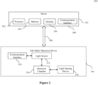
- Figure 2 illustrates a system 200 for evaluating the operational aspect of the life safety detection device 104.
- the system 200 comprises the server 110 and the life safety detection device 104.
- the server 110 may comprise a processor 202, a memory 204, one or more modules 206, and a communication interface 208.
- the life safety detection device 104 may comprise a communication interface 210, a light source 212, and a light sensing device 214.
- the life safety detection device 104 may include a housing (not shown in Fig. 2 ) defining a detection chamber 216 for receiving ambient materials, such as particulate matter of a predefined size in microns (e.g., PM 2.5 and PM 10).
- the light source 212 may be configured to emit/transmit light into the detection chamber 216 positioned within an interior of the housing of the life safety detection device 104.
- the light sensing device 214 may be configured to receive, over a predefined time period, scattered light within the detection chamber 216, wherein the scattered light is indicative of a presence of the airborne particulate matter in the life safety detection device 104.
- each of the communication interfaces 208 and 210 may include a transmitter and a receiver, and may be configured to communicate with each other via communication network 108, such as a wireless communication protocol.
- the communication interface 210 of the life safety detection device 104 may be configured to indirectly communicate with the server 110.
- the communication interface 210 may be configured to provide measurements associated with the particulate matter (i.e., the scattered light) to one or more devices (e.g., a router, a gateway, a fire panel, etc.) located within the area 102a-102b via wired or wireless communication. Subsequently, the one or more devices may be configured to transmit the measurements to the server 110 wirelessly.
- the communication interface 208 coupled with the processor 202 may be configured to transmit an alert indicating malfunctioning of the life safety detection device 104 based on the evaluation of the operational aspects of the life safety detection device 104.
- the communication interfaces 208 and 210 may be configured for communicating internally between internal hardware components and with external devices, e.g., the life safety detection device 104 as well as the PM sensor device 106 (as shown in Figure 1 ), via one or more networks (e.g., radio technology).
- the communication interfaces 208 and 210 may each include an electronic circuit specific to a standard that enables wired or wireless communication.
- the processor(s) 202 of the server 110 may be configured to receive the measurements associated with the particulate matter from the life safety detection device 104 and evaluate one or more operational aspects of the life safety detection device 104 based on an analysis of the measurements, as discussed throughout the disclosure.
- the processor(s) 202 may be configured to communicate with the memory 204 to store the received measurements for processing and evaluating the operational aspects of the life safety detection device 104.
- the processor(s) 202 may be one or more microprocessor(s) or microcontroller(s).
- the processor 202 may include one or a plurality of processors, may be a general-purpose processor, such as a central processing unit (CPU), an application processor (AP), or the like, a graphics-only processing unit such as a graphics processing unit (GPU), a visual processing unit (VPU), and/or an Artificial intelligence (AI) dedicated processor such as a neural processing unit (NPU).
- CPU central processing unit
- AP application processor
- AI Artificial intelligence
- the memory 204 may store data, instructions executable by the processor(s) 202 to perform the methods of evaluating the operational aspects of the life safety detection device 104, as discussed throughout the disclosure.
- the memory 204 may further include, but not limited to, a non-transitory computer-readable storage media such as various types of volatile and non-volatile storage media, including but not limited to, random access memory, read-only memory, programmable read-only memory, electrically programmable read-only memory, electrically erasable read-only memory, flash memory, magnetic tape or disk, optical media and the like.
- the non-transitory computer-readable storage media of the memory 204 may include executable instructions in a form of the modules 206 and a database to store data.
- the modules 206 may include a set of instructions that may be executed to cause the server 110 to perform any one or more of the methods for evaluating operational aspects of the life safety detection device 104 based on received measurements associated with the particulate matter, as disclosed herein throughout the disclosure.
- the one or more modules 206 may be configured to perform the steps of the present disclosure using the data stored in the database of the memory 204 for evaluating operational aspects of the life safety detection device 104.
- the modules 206 may be one or more hardware units which may be outside the memory 204.
- the memory 204 may communicate via a bus within the processor(s) 202.
- the server 110 may store one or more machine learning models in the memory 204 for evaluating the operational aspects of the life safety detection device 104, as discussed herein.
- the server 110 may be coupled to a remote database via the communication interface 208, wherein the remote database may be configured to store machine learning models trained to perform one or more steps of the methods to evaluate the operational aspects of the life safety detection device 104.
- Figure 3a illustrates a perspective view of the exemplary life safety detection device 104.
- Figure 3b illustrates a partially exploded view of the life safety detection device 104 of FIG. 3a .
- Figure 4 illustrates a planar view of a portion of the life safety detection device 104.
- Figures 3a , 3b , and 4 are described in conjunction with each other for the sake of ease of explanation.
- the life safety detection device 20 may correspond to the life safety detection device 104, as explained previously in conjunction with Figs. 1 and 2 .
- the life safety detection device 20 includes a housing 22 including a first upper housing portion 24 and a second lower housing portion 26 that is permanently or removably connected to the first housing portion 24. When the first and second housing portions 24, 26 are connected, the first and second housing portions 24, 26 enclose the controls and other components necessary for operation of the device 20.
- the terms “upper”, “lower”, and the like are in reference to the device 20 in use as it is mounted on a surface, such as a ceiling in a building for example. Therefore, the upper housing portion 24 is typically closer to the ceiling than the lower housing portion 26, and the lower housing portion 26 is typically the portion of the device 20 that will face downward toward the floor of the building. In some embodiments, device 20 may be mounted on a wall such that upper housing portion 24 is closer to the wall than the lower housing portion 26, and the lower housing portion 26 is typically the portion of the device 20 that will face outward toward the interior space of the room or space to be monitored.
- the life safety detection device 20 further includes controls including a printed circuit board 30 disposed within the first housing portion 24.
- the printed circuit board 30 includes the circuitry and/or components associated with at least one detection circuit (not shown) and at least one alarm circuit (not shown).
- the device 20 may be hardwired to a power source (not shown) located within the building or area where the device 20 is mounted, remote from the device 20.
- the printed circuit board 30 may be directly or indirectly connected to the power source.
- the device 20 may include a compartment 32 for receiving one or more batteries sufficient to provide the power necessary to operate the device 20 for an extended period of time.
- the power provided by the batteries may be the sole source of power used to operate the device 20.
- the battery power may be supplemental to the remote power source, for example in the event of a failure or loss of power at the power source.
- a sound generation mechanism 34 may be connected to the printed circuit board 30 within the housing 22.
- the sound generation mechanism 34 may be operable to receive power from the printed circuit board 30 to generate a noise in response to detection of a condition.
- one or more actuatable mechanisms 36 such as a button for example, may be connected to the printed circuit board 30 and is received within an opening formed in the second housing portion 26.
- the actuatable mechanism 36 may be configured to perform one or more functions of the life safety detection device 20 when actuated.
- Examples of operations performed via the actuatable mechanism 36 include, but are not limited to, a press to test function, a smoke alarm "hush", a low battery “hush”, and end of life “hush”, radio frequency enrolment of additional life safety detection devices 20 such as in a detection system including a plurality of life safety detection devices configured to communicate with one another wirelessly, and to reset the unit once removed from its packaging.
- a press to test function a smoke alarm "hush”, a low battery “hush”, and end of life “hush”
- radio frequency enrolment of additional life safety detection devices 20 such as in a detection system including a plurality of life safety detection devices configured to communicate with one another wirelessly, and to reset the unit once removed from its packaging.
- the life safety detection device 20 additionally includes one or more components that define an optical chamber assembly 40 within the interior of the housing 22.
- the optical chamber assembly 40 is generally open to or in fluid communication with the area surrounding the life safety detection device 20 and is thus receptive of ambient materials through a grating or another similar feature.
- the ambient materials may include air as well as smoke and non-smoke particles that are carried by the air.
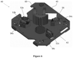
- the optical chamber assembly 40 includes a base 42.
- the circuit board 30 may be positioned between the base 42 and the first housing portion 24 to mechanically support and electrically connect electronic components of the device 20.
- An optical cover 44 is removably or permanently attached to the base 42 adjacent to a first surface 43 thereof. Accordingly, a detection chamber 46 is formed between the interior surface 48 of the optical cover 44 and the surface 43 of the base 42.
- the second housing portion 26 includes at least one entry portion 50 through which air having particles entrained therein may enter into the life safety detection device 20.
- the second housing portion 26 may be connectable to the first housing portion 24 in overlapping arrangement with the optical cover 44.
- the one or more entry portions 50 are arranged in fluid communication with and form part of a fluid flow path for delivering air and any particles entrained therein from the atmosphere surrounding the device 20 into the detection chamber 46.
- the optical chamber assembly 40 additionally includes at least one light source, such as a light emitting diode for example.
- the at least one light source includes a first light source 52a, a second light source 52b, and a third light source 52c.
- the base 42 includes at least one mounting portion for supporting the at least one light source.
- the first light source 52a and the second light source 52b are arranged at a first mounting portion 54a relative to the base 42.
- Embodiments where the first light source 52a and the second light source 52b are mounted to distinct mounting portions at the same or different locations relative to the detection chamber 46 are contemplated herein.
- the first light source 52a and the second light sources 52b may be selected to emit light having different wavelengths.
- the first light source 52a may emit a first light having a first color and the second light source 52b may emit a second light having a second, distinct color.
- the first light source 52a may emit a first light within a visible spectrum and the second light source 52b may emit a second light outside of the visible spectrum, such as infrared light for example.
- a second mounting portion 54b located remotely from the first mounting portion 54a, may be configured to support the third light source 52c.
- the third light source 52c is arranged at an angle to the light emitted by the first and second light sources 52a, 52b and may emit light having the same wavelength and/or color or a different wavelength and/or color than the first and second light sources 52a, 52b.
- a single light source such as the first light source 52a for example, may be operable to emit light at two or more different wavelengths. Examples of such a light source include, but not limited to, a bi-color LED.
- the optical chamber assembly 40 may have only the single light source, or alternatively, may include multiple light sources, at least one of which is configured to emit light at a plurality of different wavelengths.
- the optical chamber assembly 40 additionally includes at least one light sensing device or light receiver 56.
- the light sensing device or the light receiver 56 include, but are not limited to a photodiode, an Avalanche PhotoDiode (APDs), a Multi-Pixel Photon Counters (MPPCs), or another suitable photodetector.
- APDs Avalanche PhotoDiode
- MPPCs Multi-Pixel Photon Counters
- a single light receiver 56 is illustrated in the figures, it should be understood that in other embodiments, the optical chamber assembly 40 may include two or more light receivers.
- a third mounting portion 54c separate from the first and second mounting portions 54a, 54b, is operable to support the light receiver 56.
- the light receiver 56 is disposed to receive light that is emitted by one of the light sources 52a, 52b, 52c and that is then reflected by the ambient materials within the detection chamber 46 toward the light receiver 56.
- the light emitted from each of the light sources defines an emitter cone.
- the light emitted from the first light source 52a defines a first emitter cone
- the light emitted by the second light source 52b defines a second emitter cone
- the light emitted by the third light source 52c defines a third emitter cone.
- the at least one light receiver 56 similarly has a receiving cone associated therewith.
- the volume where each emitter cone overlaps with the receiving cone is defined as a sensing volume. Accordingly, in the illustrated, non-limiting embodiment, a first sensing volume is defined between the first emitter cone and the receiving cone, a second sensing volume is defined between the second emitter cone and the receiving cone and a third sensing volume is defined between the third emitter cone and the receiving cone.
- the light receiver 56 may be configured to generate an electric output signal in accordance with light being received. That is, for light that is emitted by the first light source 52a, reflected by the ambient materials in the detection chamber 46 and then received by the light receiver 56, the light receiver 56 generates a first output signal. Similarly, for light that is emitted by the second and third light sources 52b, 52c, reflected by the ambient materials in the detection chamber 46 and then received by the light receiver 56, the light receiver 56 generates a second and third output signal, respectively.
- each of the mounting portions 54a, 54b, 54c may be oriented such that the corresponding light source 52a, 52b, 52c or light receiver 56 located thereat is arranged at a desired angle relative to a horizontal plane.
- the life safety detection device 20 further includes a processing device C (e.g., a processor) in electrical communication with the plurality of light sources 52a, 52b, 52c, and the light receiver 56.
- the processing device C may be capable of accessing executable instructions or may include a memory (not shown) capable of storing executable instructions.
- the executable instructions may be stored or organized in any manner and at any level of abstraction, such as in connection with one or more applications, processes or routines to analyze the signals detected by the one or more light receivers to make alarm decisions after pre-set threshold levels are reached according to the method described herein.
- the life safety detection device 20 may be operable in a plurality of modes.
- the life safety detection device 20 is configured to detect the presence of smoke within the ambient atmosphere surrounding the life safety detection device 20 during operation in a first mode and is configured to monitor the indoor air quality of the ambient atmosphere surrounding the life safety detection device 20 during operation in a second mode.
- Monitoring of the indoor air quality as described herein relates to the detection of dust or other airborne particles referred to as PM2.5 particles (those particles having a diameter of 2.5 micrometers or less) and PM10 particles (those particles having a diameter of 10 micrometers or less).
- the life safety detection device 20 includes additional components or electronics associated with operation in the second or "indoor air quality" mode. Such components may be used to improve the detection sensitivity of the life safety detection device 20.
- the additional components include an analog to digital converter and/or an optical filter.
- the optical filter may be configured to filter out undesired wavelengths, such as wavelengths outside of the wavelengths emitted by the light sources 52a, 52b, and 52c, or to preferentially detect with a specific polarization or scattered light from PM2.5 particles or smoke particles over light reflected from the side of the chamber.
- One or more parameters associated with sampling of the atmosphere within the detection chamber 46 of the optical chamber assembly 40 may be the same, or alternatively, may vary based the mode of operation of the life safety detection device 20.
- the sensing volumes and/or wavelengths may be different for the smoke detection mode and indoor air quality mode.
- operation in the indoor air quality mode may include amplification of the detection circuit at the processor C, such as by using additional bits on the analog to digital converter to increase the resolution of the signal.
- the indoor air quality mode may have an increased time during which at least one light source 52a-52c is energized compared to operation in the first "smoke detection” mode, and/or increased intensity or brightness of light emitted by a light source 52a-52c (due to an increased power input) relative to operation in the "smoke detection” mode.
- the reference voltage of the analog to digital converter varies between the smoke detection mode and the indoor air quality mode.
- the life safety detection device 20 may be configured to automatically transform between operation in the first smoke detection mode and operation in the second indoor air quality mode at predetermined intervals.
- the timing of the intervals may be delayed or paused.
- the intervals at which measurements are taken during operation in the smoke detection mode may be the same, or alternatively, may be different than the intervals at which measurements are taken during operation in the indoor air quality mode.
- operation in either mode includes continuous monitoring rather than sampling at intervals is also within the scope of the disclosure.
- Figure 8 illustrates a flow diagram depicting an exemplary method at a system (e.g., 200) comprising a server (e.g., 110) and a life safety detection device (e.g., 104) for evaluating an operational aspect of a life safety detection device.
- a system e.g., 200
- a server e.g., 110
- a life safety detection device e.g., 104
- the method 800 comprises receiving, over a predefined time period, scattered light within the detection chamber, wherein the scattered light is indicative of a presence of airborne particulate matter.
- the method 800 comprises determining, by at least one processor communicably coupled to the life safety detection device, a variation pattern of the airborne particulate matter during the predefined time period based on the received scattered light during the predefined time period.
- the determining comprises determining a variation pattern of the airborne particulate matter indicative of perturbation in the airborne particulate matter during an active stimulus associated with an event within a predefined threshold distance from the life safety detection device, and wherein the event perturbs air quality within the predefined threshold distance.
- the event may include one or more of activating or deactivating of a device within the predefined threshold distance, activating or deactivating of a sub-alarm threshold aerosol within the predefined threshold distance, change in state of one of a door, a window, or an object within the predefined threshold distance, and activating or deactivating of a ventilation system within the predefined threshold distance.
- the analyzing may include determining whether a deviation between the variation pattern of the airborne particulate matter and the another variation pattern is within a predefined threshold.
- the analyzing may include a passive trend analysis which can be achieved by monitoring via life safety detection devices in geometric proximity to each other and performing a statistical analysis, to verify whether a systemic change in correlation has not occurred over time. For instance, 7-day or 30-day average of a correlation coefficient may remain within a historically-observed range. Such metrics would be unique to a given deployment but would remain relatively constant over time unless an anomaly has occurred to an individual detector.
- the method 800 comprises transmitting, by the at least one processor, an alert indicating malfunctioning of the life safety detection device based on the evaluating step.
- Figure 9 illustrates a flow diagram depicting an exemplary method at the life safety detection device (e.g., 104) for evaluating the operational aspects of the life safety detection device.
- the method 900 comprises transmitting light from at least one light source into a detection chamber positioned within an interior of a housing of the life safety detection device.
- the method 900 comprises receiving, over a predefined time period, scattered light within the detection chamber, wherein the scattered light is indicative of a presence of airborne particulate matter.
- the method 900 comprises transmitting, to at least one processor communicably coupled to the life safety detection device, measurements associated with the received scattered light indicating presence of airborne particulate matter for evaluation of an operational aspect of the life safety detection device.
- the method 1000 comprises receiving, by at least one processor communicably coupled to the life safety detection device, measurements associated with received scattered light at the life safety detection device indicating presence of airborne particulate matter during a predefined time period.
- the method 1000 comprises determining, by the at least one processor, a variation pattern of the airborne particulate matter during the predefined time period based on the received scattered light during the predefined time period.
- the determining may include determining a variation pattern of the airborne particulate matter indicative of perturbation in the airborne particulate matter during an active stimulus associated with an event within a predefined threshold distance from the life safety detection device, and wherein the event perturbs air quality within the predefined threshold distance.
- the method 1000 comprises analyzing, by the at least one processor, the variation pattern of the airborne particulate matter over the predefined time period with respect to another variation pattern during the predefined time duration.
- the analyzing comprises determining whether a deviation between the variation pattern of the airborne particulate matter and the another variation pattern is within a predefined threshold.
- the method 1000 comprises evaluating, by the at least one processor, the operational aspect associated with the life safety detection device based on the analysis.
- the evaluating comprises evaluating that the life safety detection device is malfunctioning in response to a determining that the deviation is above a predefined threshold.
- the method 1000 comprises transmitting, by the at least one processor, an alert indicating malfunctioning of the life safety detection device based on the evaluating step.
- Figure 11 illustrates a graphical representation of measurements associated with the particulate matter sensing functionality of the life safety detection device. As depicted, even small changes in background particulate matter trends, such as the increase at time index 11:26, are detectable through this enhanced sensing functionality, which is not present in typical life safety devices. Further, the particulate matter trends detected via life safety detection device may be used to verify unimpeded air flow being present around the life safety device.
- a method of evaluating an operational aspect of a life safety detection device comprises transmitting light from at least one light source into a detection chamber positioned within an interior of a housing of the life safety detection device. Further, the method comprises receiving, over a predefined time period, scattered light within the detection chamber, wherein the scattered light is indicative of a presence of airborne particulate matter. Furthermore, the method comprises transmitting, to at least one processor communicably coupled to the life safety detection device, measurements associated with the received scattered light indicating presence of airborne particulate matter for evaluation of an operational aspect of the life safety detection device.
- a system of evaluating an operational aspect of a life safety detection device comprises at least one processor communicably coupled to the life safety detection device.
- the at least one processor is configured to receive, from the life safety detection device, measurements associated with received scattered light indicating presence of airborne particulate matter during a predefined time period. Further, the at least one processor is configured to determine a variation pattern of the airborne particulate matter during the predefined time period based on the received scattered light during the predefined time period. Furthermore, the at least one processor is configured to analyze the variation pattern of the airborne particulate matter over the predefined time period with respect to another variation pattern during the predefined time duration. Furthermore, the at least one processor is configured to evaluate the operational aspect associated with the life safety detection device based on the analysis.
- the at least one processor is configured to determine a variation pattern of the airborne particulate matter indicative of perturbation in the airborne particulate matter during an active stimulus associated with an event within a predefined threshold distance from the life safety detection device, and wherein the event perturbs air quality within the predefined threshold distance.
- the event comprises one of activating or deactivating of a device within the predefined threshold distance, activating or deactivating of a sub-alarm threshold aerosol within the predefined threshold distance, change in state of one of a door, a window, or an object within the predefined threshold distance, and activating or deactivating of a ventilation system within the predefined threshold distance.
- the another variation pattern is associated with another life safety detection device within a predefined threshold distance from the life safety detection device.
- the another variation pattern is a predefined pattern associated with a ground truth airborne particulate matter detection device.
- the at least one processor is configured to determine whether a deviation between the variation pattern of the airborne particulate matter and the another variation pattern is within a predefined threshold.
- the at least one processor is configured to evaluate that the life safety detection device is malfunctioning in response to a determining that the deviation is above a predefined threshold.
- the at least one processor is further configured to transmit an alert indicating malfunctioning of the life safety detection device based on the evaluating step.
- a method of evaluating an operational aspect of a life safety detection device comprises receiving, by at least one processor communicably coupled to the life safety detection device, measurements associated with received scattered light at the life safety detection device indicating presence of airborne particulate matter during a predefined time period. Further, the method comprises determining, by the at least one processor, a variation pattern of the airborne particulate matter during the predefined time period based on the received scattered light during the predefined time period. Furthermore, the method comprises analyzing, by the at least one processor, the variation pattern of the airborne particulate matter over the predefined time period with respect to another variation pattern during the predefined time duration. Furthermore, the method comprises evaluating, by the at least one processor, the operational aspect associated with the life safety detection device based on the analysis.
- the event comprises one of activating or deactivating of a device within the predefined threshold distance, activating or deactivating of a sub-alarm threshold aerosol within the predefined threshold distance, change in state of one of a door, a window, or an object within the predefined threshold distance, and activating or deactivating of a ventilation system within the predefined threshold distance.
- the another variation pattern is associated with another life safety detection device within a predefined threshold distance from the life safety detection device.
- the another variation pattern is a predefined pattern associated with a ground truth airborne particulate matter detection device.
- the analyzing comprises determining whether a deviation between the variation pattern of the airborne particulate matter and the another variation pattern is within a predefined threshold. Further, the evaluating comprises evaluating that the life safety detection device is malfunctioning in response to a determining that the deviation is above a predefined threshold.
- the method further comprises transmitting, by the at least one processor, an alert indicating malfunctioning of the life safety detection device based on the evaluating step.
Landscapes
- Physics & Mathematics (AREA)
- General Physics & Mathematics (AREA)
- Chemical & Material Sciences (AREA)
- Analytical Chemistry (AREA)
- Business, Economics & Management (AREA)
- Emergency Management (AREA)
- Engineering & Computer Science (AREA)
- Computer Security & Cryptography (AREA)
- Fire-Detection Mechanisms (AREA)
- Investigating Or Analysing Materials By Optical Means (AREA)
Abstract
Embodiments of the disclosure describe systems and methods for evaluating an operational aspect of a life safety detection device (20, 104). The method comprises transmitting light from at least one light source (212) into a detection chamber (216) positioned within an interior of a housing (22) of the device. Further, the method comprises receiving, over a predefined time period, scattered light within the detection chamber, wherein the scattered light is indicative of a presence of airborne particulate matter. Furthermore, the method comprises determining, by a processor (202) coupled to the device, a variation pattern of the airborne particulate matter during the predefined time period to analyze, by the processor, the variation pattern of the airborne particulate matter over the predefined time period with respect to another variation pattern during the predefined time duration to evaluate operational aspects of the device.
Description
- This application claims the benefit of
U.S. Provisional Patent Application No. 63/504,551 filed on May 26, 2023 - The disclosure generally relates to life safety detection devices, and more particularly relates to evaluating one or more operational aspects of life safety detection devices (e.g., a smoke detector).
- Residential and commercial facilities may have life safety detection devices (e.g., photoelectric smoke detectors) that are used to warn occupants during an emergency situation (e.g., a fire). Conventional photoelectric smoke detectors include a light source and a photoelectric receiver to detect whether or not smoke is present in an optic/smoke chamber of the smoke detector. When there is no smoke in the optic/smoke chamber, and the optic chamber is empty or mostly empty, the photoelectric receiver typically receives a small amount of light reflected from the chamber surfaces. On the other hand, when smoke is present in the optic chamber, the photoelectric receiver receives more light due to the light being reflected from the smoke particles. When an amount of the light received by the receiver exceeds a certain threshold, an alarm is triggered. Such smoke detectors need to be periodically tested to check their smooth functioning to ensure safety of the occupants.
- Currently, such smoke detectors have to be tested manually by at least two technicians, one at a fire panel and another one walking around with a "smoke-in-a-can" product, to verify the life-safety performance (i.e., smoke detection) of the smoke detector. For verifying smoke detection functionality, the manual testers have to verify whether the photo-sensor of the smoke detector is functioning correctly, and whether smoke can enter the smoke chamber, i.e., there are no obstructions in the surrounding area of the detector. This maintenance service is expensive to the customer and also consumes a lot of time.
- Additionally, some current solutions use an active stimulus, such as heating of wax to generate particles to test optic/smoke chambers of such life safety detection devices. However, such testing processes are also costly and have high power-consumption, which can be problematic for low-power detection networks.
- Therefore, in view of the above-mentioned problems, there is a need to provide a method and a system for efficient testing of aforementioned life safety detection devices, which may also reduce cost, eliminate the need for manual service, and/or save time.
- This summary is provided to introduce a selection of concepts, in a simplified format, that are further described in the detailed description of the disclosure. This summary is neither intended to identify key or essential inventive concepts of the disclosure and nor is it intended for determining the scope of the disclosure.
- According to a first aspect of the invention there is provided a method of evaluating an operational aspect of a life safety detection device. The method comprises transmitting light from at least one light source into a detection chamber positioned within an interior of a housing of the life safety detection device. Further, the method comprises receiving, over a predefined time period, scattered light within the detection chamber, wherein the scattered light is indicative of a presence of airborne particulate matter. Furthermore, the method comprises determining, by at least one processor communicably coupled to the life safety detection device, a variation pattern of the airborne particulate matter during the predefined time period based on the received scattered light during the predefined time period. Still further, the method comprises analyzing, by the at least one processor, the variation pattern of the airborne particulate matter over the predefined time period with respect to another variation pattern during the predefined time duration. Additionally, the method comprises evaluating, by the at least one processor, the operational aspect associated with the life safety detection device based on the analyzing step.
- The determining may comprise determining a variation pattern of the airborne particulate matter indicative of perturbation in the airborne particulate matter during an active stimulus associated with an event within a predefined threshold distance from the life safety detection device, and wherein the event perturbs air quality within the predefined threshold distance.
- The event may comprise one of: activating or deactivating of a device within the predefined threshold distance, activating or deactivating of a sub-alarm threshold aerosol within the predefined threshold distance, change in state of one of a door, a window, or an object within the predefined threshold distance, and activating or deactivating of a ventilation system within the predefined threshold distance.
- The another variation pattern may be associated with another life safety detection device within a predefined threshold distance from the life safety detection device.
- The another variation pattern may be a predefined pattern associated with a ground truth airborne particulate matter detection device.
- The analyzing may comprise determining whether a deviation between the variation pattern of the airborne particulate matter and the another variation pattern is within a predefined threshold, and the evaluating may comprise evaluating that the life safety detection device is malfunctioning in response to a determining that the deviation is above the predefined threshold.
- The method may further comprise transmitting, by the at least one processor, an alert indicating malfunctioning of the life safety detection device based on the evaluating step.
- According to a second aspect of the invention there is provided a system for evaluating an operational aspect of a life safety detection device. The system comprises a life safety detection device comprising: a housing defining a detection chamber for receiving ambient materials; at least one light source configured to emit light into the detection chamber; and at least one light sensing device configured to receive, over a predefined time period, scattered light reflected from the ambient materials in the detection chamber, wherein the scattered light is indicative of a presence of airborne particulate matter. Further, the system comprises a processor communicably coupled to the life safety detection device. The processor is configured to: determine a variation pattern of the airborne particulate matter during the predefined time period based on the received scattered light at the life safety detection device during the predefined time period. Further, the processor is configured to analyze the variation pattern of the airborne particulate matter over the predefined time period with respect to another variation pattern during the predefined time duration. Furthermore, the processor is configured to evaluate the operational aspect associated with the life safety detection device based on the analysis.
- To determine the variation pattern, the processor may be configured to determine a variation pattern of the airborne particulate matter indicative of perturbation in the airborne particulate matter during an active stimulus associated with an event within a predefined threshold distance from the life safety detection device, and wherein the event perturbs air quality within the predefined threshold distance.
- The event may comprise one of: activating or deactivating of a device within the predefined threshold distance, activating or deactivating of a sub-alarm threshold aerosol within the predefined threshold distance, change in state of one of a door, a window, or an object within the predefined threshold distance, and activating or deactivating of a ventilation system within the predefined threshold distance.
- The another variation pattern may be associated with another life safety detection device within a predefined threshold distance from the life safety detection device.
- The another variation pattern may be a predefined pattern associated with a ground truth airborne particulate matter detection device.
- To analyze the variation pattern, the processor may be configured to determine whether a deviation between the variation pattern of the airborne particulate matter and the another variation pattern is within a predefined threshold, and to evaluate the operational aspect, the processor may be configured to evaluate that the life safety detection device is malfunctioning in response to a determining that the deviation is above a predefined threshold.
- The processor may be further configured to transmit an alert indicating malfunctioning of the life safety detection device based on the evaluating step.
- According to a third aspect of the invention there is provided a life safety detection device, comprising a housing defining a detection chamber for receiving ambient materials. Further, the life safety detection device comprises at least one light source configured to emit light into the detection chamber. Furthermore, the life safety detection device comprises at least one light sensing device configured to receive, over a predefined time period, scattered light reflected from the ambient materials in the detection chamber, wherein the scattered light is indicative of a presence of airborne particulate matter. Furthermore, the life safety detection device comprises a communication interface configured to transmit to a processor, communicably coupled to the life safety detection device, measurements associated with the received scattered light indicating presence of the airborne particulate matter for evaluation of an operational aspect of the life safety detection device.
- Also disclosed herein is a method of evaluating an operational aspect of a life safety detection device. The method comprises transmitting light from at least one light source into a detection chamber positioned within an interior of a housing of the life safety detection device. Further, the method comprises receiving, over a predefined time period, scattered light within the detection chamber, wherein the scattered light is indicative of a presence of airborne particulate matter. Furthermore, the method comprises transmitting, to at least one processor communicably coupled to the life safety detection device, measurements associated with the received scattered light indicating presence of airborne particulate matter for evaluation of the operational aspect of the life safety detection device.
- Also disclosed here is a system of evaluating an operational aspect of a life safety detection device. The system comprises at least one processor communicably coupled to the life safety detection device. The at least one processor is configured to receive, from the life safety detection device, measurements associated with received scattered light indicating presence of airborne particulate matter during a predefined time period. Further, the at least one processor is configured to determine a variation pattern of the airborne particulate matter during the predefined time period based on the received scattered light during the predefined time period. Furthermore, the at least one processor is configured to analyze the variation pattern of the airborne particulate matter over the predefined time period with respect to another variation pattern during the predefined time duration. Additionally, the at least one processor is configured to evaluate the operational aspect associated with the life safety detection device based on the analysis.
- To determine the variation pattern, the at least one processor may be configured to determine a variation pattern of the airborne particulate matter indicative of perturbation in the airborne particulate matter during an active stimulus associated with an event within a predefined threshold distance from the life safety detection device, and wherein the event perturbs air quality within the predefined threshold distance.
- The event may comprise one of: activating or deactivating of a device within the predefined threshold distance, activating or deactivating of a sub-alarm threshold aerosol within the predefined threshold distance, change in state of one of a door, a window, or an object within the predefined threshold distance, and activating or deactivating of a ventilation system within the predefined threshold distance.
- The another variation pattern may be associated with another life safety detection device within a predefined threshold distance from the life safety detection device.
- The another variation pattern may be a predefined pattern associated with a ground truth airborne particulate matter detection device.
- To analyze the variation pattern, the at least one processor may be configured to determine whether a deviation between the variation pattern of the airborne particulate matter and the another variation pattern is within a predefined threshold, and to evaluate the operational aspect, the at least one processor may be configured to evaluate that the life safety detection device is malfunctioning in response to a determining that the deviation is above a predefined threshold.
- The at least one processor may be further configured to transmit an alert indicating malfunctioning of the life safety detection device based on the evaluating step.
- Also disclosed herein is a method of evaluating an operational aspect of a life safety detection device. The method comprises receiving, by at least one processor communicably coupled to the life safety detection device, measurements associated with received scattered light at the life safety detection device indicating presence of airborne particulate matter during a predefined time period. Further, the method comprises determining, by the at least one processor, a variation pattern of the airborne particulate matter during the predefined time period based on the received scattered light during the predefined time period. Furthermore, the method comprises analyzing, by the at least one processor, the variation pattern of the airborne particulate matter over the predefined time period with respect to another variation pattern during the predefined time duration. Additionally, the method comprises evaluating, by the at least one processor, the operational aspect associated with the life safety detection device based on the analysis.
- The determining may comprise determining a variation pattern of the airborne particulate matter indicative of perturbation in the airborne particulate matter during an active stimulus associated with an event within a predefined threshold distance from the life safety detection device, and wherein the event perturbs air quality within the predefined threshold distance.
- The event may comprise one of: activating or deactivating of a device within the predefined threshold distance, activating or deactivating of a sub-alarm threshold aerosol within the predefined threshold distance, change in state of one of a door, a window, or an object within the predefined threshold distance, and activating or deactivating of a ventilation system within the predefined threshold distance.
- The another variation pattern may be associated with another life safety detection device within a predefined threshold distance from the life safety detection device.
- The another variation pattern may be a predefined pattern associated with a ground truth airborne particulate matter detection device.
- The analyzing may comprise determining whether a deviation between the variation pattern of the airborne particulate matter and the another variation pattern is within a predefined threshold, and the evaluating may comprise evaluating that the life safety detection device is malfunctioning in response to a determining that the deviation is above a predefined threshold.
- The method may further comprise transmitting, by the at least one processor, an alert indicating malfunctioning of the life safety detection device based on the evaluating step.
- To further clarify the advantages and features of the methods, systems, and apparatuses, a more particular description of the methods, systems, and apparatuses will be rendered by reference to specific embodiments thereof, which are illustrated in the appended drawings. It is appreciated that these drawings depict only typical embodiments of the disclosure and are therefore not to be considered limiting of its scope. The disclosure will be described and explained with additional specificity and detail with the accompanying drawings.
- These and other features, aspects, and advantages of the disclosure will become better understood when the following detailed description is read with reference to the accompanying drawings in which like characters represent like parts throughout the drawings, wherein:
-
Figure 1 illustrates an environment for evaluating an operational aspect of a life safety detection device; -
Figure 2 illustrates a system for evaluating an operational aspect of the life safety detection device; -
Figure 3a illustrates a perspective view of an exemplary life safety detection device; -
Figure 3b illustrates a partially exploded view of the life safety detection device ofFIG. 3a ; -
Figure 4 illustrates a planar view of a portion of the life safety detection device; -
Figure 5 illustrates a perspective view of an exemplary optical chamber assembly of the life safety detection device; -
Figure 6 illustrates a perspective view of a portion of the optical chamber assembly ofFIG. 5 ; -
Figure 7 illustrates a schematic diagram of an exemplary control system of the life safety detection device; -
Figure 8 illustrates a flow diagram depicting an exemplary method at a system comprising a server and the life safety detection device for evaluating an operational aspect of the life safety detection device; -
Figure 9 illustrates a flow diagram depicting an exemplary method at the life safety detection device for evaluating the operational aspect of the life safety detection device; -
Figure 10 illustrates a flow diagram depicting an exemplary method at a server for evaluating the operational aspect of the life safety detection device; and -
Figure 11 illustrates a graphical representation of measurements associated with particulate matter at the life safety detection device. - Further, skilled artisans will appreciate that elements in the drawings are illustrated for simplicity and may not have necessarily been drawn to scale. For example, the flow charts illustrate the method in terms of the most prominent steps involved to help to improve understanding of aspects of the disclosure. Furthermore, in terms of the construction of the device, one or more components of the device may have been represented in the drawings by conventional symbols, and the drawings may show only those specific details that are pertinent to understanding the embodiments of the disclosure so as not to obscure the drawings with details that will be readily apparent to those of ordinary skill in the art having the benefit of the description herein.
- For the purpose of promoting an understanding of the principles of the disclosure, reference will now be made to the various embodiments and specific language will be used to describe the same. It will nevertheless be understood that no limitation of the scope of the disclosure is thereby intended, such alterations and further modifications in the illustrated system, and such further applications of the principles of the disclosure as illustrated therein being contemplated as would normally occur to one skilled in the art to which the disclosure relates.
- It will be understood by those skilled in the art that the foregoing general description and the following detailed description are explanatory of the disclosure and are not intended to be restrictive thereof.
- Reference throughout this specification to "an aspect", "another aspect" or similar language means that a particular feature, structure, or characteristic described in connection with the embodiment is included in at least one embodiment of the disclosure. Thus, appearances of the phrase "in an embodiment", "in another embodiment", "some embodiments", "one or more embodiments" and similar language throughout this specification may, but do not necessarily, all refer to the same embodiment.
- The terms "comprises", "comprising", or any other variations thereof, are intended to cover a non-exclusive inclusion, such that a process or method that comprises a list of steps does not include only those steps but may include other steps not expressly listed or inherent to such process or method. Similarly, one or more devices or sub-systems or elements or structures or components proceeded by "comprises... a" does not, without more constraints, preclude the existence of other devices or other sub-systems or other elements or other structures or other components or additional devices or additional sub-systems or additional elements or additional structures or additional components.
- In addition to overcoming the aforementioned challenges related to manual, time-consuming, and/or costly processes to test life safety detection devices, the disclosure provides for a dual-purpose life safety detection device, such as a smoke detector. Specifically, the indoor air quality is currently being monitored by separate indoor air quality sensors which detect presence of air pollutants, such as PM2.5 and PM10. Commercially available indoor air quality sensors typically use a laser and a fan to supply air to the interior of the sensor. Integration of such a sensor into an existing smoke detector is challenging because the laser consumes more power than is typically available within the smoke detector. Further, the size of existing smoke detector(s) and the space available inside such detector(s) imposes limitations for integration of such sensor(s). In addition, inclusion of the fan poses a risk of blowing smoke away from the smoke detector. A dual-purpose life safety detection device, such as a smoke detector, which detects pollutants is described in
US Patent Application Serial No. 18/165,542 titled "COMBINATION SMOKE AND AIR QUALITY DETECTION" filed on February 07, 2023 U.S. Provisional Patent Application Serial No. 63/307,837, filed on February 8, 2022 - Embodiments of the disclosure are directed towards evaluating one or more operational aspects of a life safety detection device based on monitoring of particulate matter at the life safety detection device. The monitored particulate matter may be compared with pre-existing air-quality trend data to infer that the life safety detection device is functioning in a smooth manner. More specifically, the evaluation of the one or more operational aspects based on monitoring of particulate matter verifies functionality of smoke detection, photo-sensor, and whether smoke can enter the smoke chamber.
- Embodiments of the disclosure will be described below in detail with reference to the accompanying drawings.
-
Figure 1 illustrates an environment for evaluating an operational aspect of a life safety detection device. - In one exemplary embodiment, the
environment 100 may include one ormore areas areas 102a-102b may correspond to, but not limited to, a living room area, a bedroom, and a conference room. Theenvironment 100 may include one or more devices, such as, but not limited to, a lifesafety detection device 104 and a particulate matter (PM)sensor device 106, as discussed throughout the disclosure. Such area is shown only for illustrative purposes, and a person skilled in the art would understand that the environment may include other areas as well comprising one or more aforementioned devices, without departing from the scope of the disclosure. - In an embodiment, the life
safety detection device 104 may be a smoke detector, which may be configured to detect smoke and trigger an alarm to indicate a hazard (e.g., fire) as an indicator for occupants to evacuate thearea 102a-102b. Further, the lifesafety detection device 104 may be configured to detect and measure airborne particulate matter, such as PM 2.5 and PM 10 within thearea 102a-102b. For detecting/measuring the airborne particulate matter, the lifesafety detection device 104 may include at least one light source (e.g., a light emitting diode) and a detection chamber positioned within an interior of a housing of the lifesafety detection device 104, wherein the light source may be configured to transmit light into a detection chamber. The detection chamber may be configured to receive scattered light over a predefined time period, wherein the scattered light is indicative of a presence of the airborne particulate matter. The detailed components, such as the light source and the detection chamber, of the lifesafety detection device 104 are explained later throughout the disclosure. - Further, the life
safety detection device 104 may be configured to transmit measurements associated with the airborne particulate matter, to theserver 110, for evaluation of one or more operational aspects of the lifesafety detection device 104. The one or more operational aspects may include, but not limited to, functioning of at least one sensor inside the lifesafety detection device 104, whether smoke is able to enter a smoke chamber of the lifesafety detection device 104, and whether there are any obstructions in an area surrounding the lifesafety detection device 104. - In an embodiment, the
environment 100 may include theserver 110, which may be communicably coupled to the lifesafety detection device 104. In an embodiment, theserver 110 may be a cloud-based server coupled to the lifesafety communication device 104 via acommunication network 108. Theserver 110 may also include one or more machine learning models trained to determine a pattern based on the measurements, as received from the lifesafety detection device 104, and to analyze the pattern associated with the airborne particulate matter, as explained throughout the disclosure. - Specifically, the
server 110 may be configured to receive measurements associated with the airborne particulate matter (or scattered light) from the lifesafety detection device 104 to evaluate the functioning of the lifesafety detection device 104. The measurements may be received corresponding to a predefined time period, such as, but not limited to, 30 mins to 1 hour. In an embodiment, theserver 110 may be configured to determine a variation pattern of the airborne particulate matter during the predefined time period based on the received scattered light during the predefined time period. - In one embodiment, the
server 110 may be configured to determine the variation pattern of the airborne particulate matter indicative of one or more perturbations in the airborne particulate matter within a predefined threshold distance from the lifesafety detection device 104. The variation pattern may subsequently be compared with another variation pattern during the predefined time duration. For instance, the another variation pattern may be associated with another life safety detection device located within thesame area 102a-102b or the building observed during the same period. In such an embodiment, theserver 110 may also be configured to receive particulate matter measurements associated with the other such device during the same period. In another exemplary embodiment, the another variation pattern may be a predefined pattern associated with a ground truth airborne particulatematter detection device 106. Thedetection device 106 may include, but not limited to, an air purifier, or any device comprising a particulate matter sensor. In yet another embodiment, the another variation pattern may be associated with a pre-defined pattern of the particulate matter available at the server that may correspond to an ideal pattern that should have been observed for the lifesafety detection device 104. - In another embodiment, the
server 110 may be configured to determine the variation pattern of the airborne particulate matter indicative of one or more perturbations in the airborne particulate matter during an active stimulus associated with an event within a predefined threshold distance from the lifesafety detection device 104. The events may perturb the air quality within such predefined threshold distance from the lifesafety detection device 104, thereby modifying the detection/measurement of particulate matter by the lifesafety detection device 104 during the event. The event/perturbations may be determined by constantly determining some errors in the variation pattern, which account for variable/unforeseen events, such as door openings. The variation pattern may then be compared with another variation pattern during the predefined time duration to confirm such events and also estimate a confidence level in correct determination of such events. Additionally, in some embodiments, the variation pattern observed during the same time duration may be correlated with data from one or more access systems comprising one or more door sensors to determine a confidence level in detection of such events related to door openings. However, in one embodiment, if the estimated confidence, upon comparison of the variation pattern with another variation patterns or sensor data, drops below a predefined threshold level, a deviation state may be indicated, and if the deviation persists, then theserver 110 may produce a maintenance fault after a predetermined period. - In one embodiment, the event may include activating or deactivating of a device and/or a ventilation system within the predefined threshold distance. For instance, activating an air purifier, a fan, or a ventilation system may perturb/modify air quality within vicinity of the life
safety detection device 104. In another embodiment, the event may include activating or deactivating of a sub-alarm threshold aerosol within the predefined threshold distance. For instance, a diffuse salt spray through the ventilation system may perturb air quality around the lifesafety detection device 104 and observing reproducible propagation behavior to indicate normal function. In yet another embodiment, the event may include change in state of one of a door, a window, or an object within the predefined threshold distance. For instance, the opening or closing of a door window may modify air flow within thearea 102a, thereby causing a perturbation in the particulate matter around the lifesafety detection device 104. - The
server 110 may be configured to determine the pattern(s) based on the received measurements using a trained artificial intelligence model or a data science model. The artificial intelligence model may be obtained by training. Here, "obtained by training" means that a predefined operation rule or artificial intelligence model configured to perform a desired feature (or purpose) is obtained by training a basic artificial intelligence model with multiple pieces of training data by a training technique. The artificial intelligence model (e.g., a neural network) may include a plurality of neural network layers. Each layer has a plurality of weight values and performs a neural network layer operation through calculation between a result of computation of a previous layer and an operation of a plurality of weights. In particular, theserver 110 may include one or more ML based artificial intelligence models that are used for processing of the received measurements associated with the lifesafety detection device 104 and determine a pattern of variation for the measurements. - Further, the
server 110 may be configured to analyze the variation pattern of the airborne particulate matter over the predefined time period with respect to another variation pattern during the predefined time duration. In an exemplary embodiment, the another variation pattern may be associated with a different life safety detection device within a predefined threshold distance from the lifesafety detection device 104. For instance, the another variation pattern may be associated with another life safety detection device located within thesame area 102a-102b or the building. In another exemplary embodiment, the another variation pattern may be a predefined pattern associated with a ground truth airborne particulate matter sensor in thedetection device 106. Thedetection device 106 may include, but not limited to, an air purifier, or any device comprising a particulate matter sensor. In yet another embodiment, the another variation pattern may be associated with a pre-defined pattern of the particulate matter available at theserver 110 that may correspond to an ideal pattern to be observed during one or more pre-defined events observed around the lifesafety detection device 104. In an alternative embodiment, one or more functions performed by theserver 110 may be locally performed by a processor and a memory included within the lifesafety detection device 104. - Furthermore, to perform the said analysis, the
server 110 may perform a passive trend analysis which can be achieved by monitoring via life safety detection devices in geometric proximity to each other and performing a statistical analysis, to verify whether a systemic change in correlation has not occurred over time. For example, 7-day or 30-day average of a correlation coefficient may remain within a historically-observed range. Such metrics would be unique to a given deployment but would remain relatively constant over time unless an anomaly has occurred to an individual detector. - Furthermore, the
server 110 may be configured to evaluate the operational aspect(s) associated with the lifesafety detection device 104 based on the aforementioned analysis of the pattern with respect to another pattern. Based on the analysis, theserver 110 may be configured to conclude a consistent behavior or absence of any anomalies with respect to the another pattern. Such conclusion may indicate proper functioning of the particulate matter detection as well as normal functioning of smoke detection feature with respect to the ability of the particles to enter the smoke chamber in the lifesafety detection device 104. On the other hand, if the server detects a deviation from the normal with respect to the other particulate matter pattern, an alert may be transmitted to a third party (e.g., maintenance department for life safety detection device 104) for manual inspection of the lifesafety detection device 104. Thus, the evaluation of such operational aspects of the lifesafety detection device 104 in this manner provides an automated testing (no manual intervention) method for such devices. -
Figure 2 illustrates asystem 200 for evaluating the operational aspect of the lifesafety detection device 104. - As illustrated, the
system 200 comprises theserver 110 and the lifesafety detection device 104. In one embodiment, theserver 110 may comprise aprocessor 202, amemory 204, one ormore modules 206, and acommunication interface 208. The lifesafety detection device 104 may comprise acommunication interface 210, alight source 212, and alight sensing device 214. - In one embodiment, the life
safety detection device 104 may include a housing (not shown inFig. 2 ) defining adetection chamber 216 for receiving ambient materials, such as particulate matter of a predefined size in microns (e.g., PM 2.5 and PM 10). Further, thelight source 212 may be configured to emit/transmit light into thedetection chamber 216 positioned within an interior of the housing of the lifesafety detection device 104. Further, thelight sensing device 214 may be configured to receive, over a predefined time period, scattered light within thedetection chamber 216, wherein the scattered light is indicative of a presence of the airborne particulate matter in the lifesafety detection device 104. - In one embodiment, each of the communication interfaces 208 and 210 may include a transmitter and a receiver, and may be configured to communicate with each other via
communication network 108, such as a wireless communication protocol. In one embodiment, thecommunication interface 210 of the lifesafety detection device 104 may be configured to indirectly communicate with theserver 110. Specifically, thecommunication interface 210 may be configured to provide measurements associated with the particulate matter (i.e., the scattered light) to one or more devices (e.g., a router, a gateway, a fire panel, etc.) located within thearea 102a-102b via wired or wireless communication. Subsequently, the one or more devices may be configured to transmit the measurements to theserver 110 wirelessly. Additionally, thecommunication interface 208 coupled with theprocessor 202 may be configured to transmit an alert indicating malfunctioning of the lifesafety detection device 104 based on the evaluation of the operational aspects of the lifesafety detection device 104. The communication interfaces 208 and 210 may be configured for communicating internally between internal hardware components and with external devices, e.g., the lifesafety detection device 104 as well as the PM sensor device 106 (as shown inFigure 1 ), via one or more networks (e.g., radio technology). The communication interfaces 208 and 210 may each include an electronic circuit specific to a standard that enables wired or wireless communication. - In one embodiment, the processor(s) 202 of the
server 110 may be configured to receive the measurements associated with the particulate matter from the lifesafety detection device 104 and evaluate one or more operational aspects of the lifesafety detection device 104 based on an analysis of the measurements, as discussed throughout the disclosure. - Further, the processor(s) 202 may be configured to communicate with the
memory 204 to store the received measurements for processing and evaluating the operational aspects of the lifesafety detection device 104. In an embodiment, the processor(s) 202 may be one or more microprocessor(s) or microcontroller(s). Theprocessor 202 may include one or a plurality of processors, may be a general-purpose processor, such as a central processing unit (CPU), an application processor (AP), or the like, a graphics-only processing unit such as a graphics processing unit (GPU), a visual processing unit (VPU), and/or an Artificial intelligence (AI) dedicated processor such as a neural processing unit (NPU). - In some embodiments, the
memory 204 may store data, instructions executable by the processor(s) 202 to perform the methods of evaluating the operational aspects of the lifesafety detection device 104, as discussed throughout the disclosure. Thememory 204 may further include, but not limited to, a non-transitory computer-readable storage media such as various types of volatile and non-volatile storage media, including but not limited to, random access memory, read-only memory, programmable read-only memory, electrically programmable read-only memory, electrically erasable read-only memory, flash memory, magnetic tape or disk, optical media and the like. Further, the non-transitory computer-readable storage media of thememory 204 may include executable instructions in a form of themodules 206 and a database to store data. Themodules 206 may include a set of instructions that may be executed to cause theserver 110 to perform any one or more of the methods for evaluating operational aspects of the lifesafety detection device 104 based on received measurements associated with the particulate matter, as disclosed herein throughout the disclosure. Specifically, the one ormore modules 206 may be configured to perform the steps of the present disclosure using the data stored in the database of thememory 204 for evaluating operational aspects of the lifesafety detection device 104. In another embodiment, themodules 206 may be one or more hardware units which may be outside thememory 204. In one embodiment, thememory 204 may communicate via a bus within the processor(s) 202. - Further, in one embodiment, the
server 110 may store one or more machine learning models in thememory 204 for evaluating the operational aspects of the lifesafety detection device 104, as discussed herein. In another embodiment, theserver 110 may be coupled to a remote database via thecommunication interface 208, wherein the remote database may be configured to store machine learning models trained to perform one or more steps of the methods to evaluate the operational aspects of the lifesafety detection device 104. -
Figure 3a illustrates a perspective view of the exemplary lifesafety detection device 104.Figure 3b illustrates a partially exploded view of the lifesafety detection device 104 ofFIG. 3a .Figure 4 illustrates a planar view of a portion of the lifesafety detection device 104.Figures 3a ,3b , and4 are described in conjunction with each other for the sake of ease of explanation. - With reference now to
FIGS. 3a ,3b , and4 , an example of a lifesafety detection device 20, such as a photoelectric smoke detector or alarm for example, is illustrated. The lifesafety detection device 20 may correspond to the lifesafety detection device 104, as explained previously in conjunction withFigs. 1 and2 . As shown, the lifesafety detection device 20 includes ahousing 22 including a firstupper housing portion 24 and a secondlower housing portion 26 that is permanently or removably connected to thefirst housing portion 24. When the first andsecond housing portions second housing portions device 20. As used herein, the terms "upper", "lower", and the like are in reference to thedevice 20 in use as it is mounted on a surface, such as a ceiling in a building for example. Therefore, theupper housing portion 24 is typically closer to the ceiling than thelower housing portion 26, and thelower housing portion 26 is typically the portion of thedevice 20 that will face downward toward the floor of the building. In some embodiments,device 20 may be mounted on a wall such thatupper housing portion 24 is closer to the wall than thelower housing portion 26, and thelower housing portion 26 is typically the portion of thedevice 20 that will face outward toward the interior space of the room or space to be monitored. - As shown in
FIGs. 4 and5 , the lifesafety detection device 20 further includes controls including a printedcircuit board 30 disposed within thefirst housing portion 24. The printedcircuit board 30 includes the circuitry and/or components associated with at least one detection circuit (not shown) and at least one alarm circuit (not shown). In some embodiments, thedevice 20 may be hardwired to a power source (not shown) located within the building or area where thedevice 20 is mounted, remote from thedevice 20. In such embodiments, the printedcircuit board 30 may be directly or indirectly connected to the power source. In an embodiment, thedevice 20 may include acompartment 32 for receiving one or more batteries sufficient to provide the power necessary to operate thedevice 20 for an extended period of time. In an embodiment, the power provided by the batteries may be the sole source of power used to operate thedevice 20. However, in other embodiments, the battery power may be supplemental to the remote power source, for example in the event of a failure or loss of power at the power source. - A
sound generation mechanism 34 may be connected to the printedcircuit board 30 within thehousing 22. Thesound generation mechanism 34 may be operable to receive power from the printedcircuit board 30 to generate a noise in response to detection of a condition. In addition, one or moreactuatable mechanisms 36, such as a button for example, may be connected to the printedcircuit board 30 and is received within an opening formed in thesecond housing portion 26. Theactuatable mechanism 36 may be configured to perform one or more functions of the lifesafety detection device 20 when actuated. Examples of operations performed via theactuatable mechanism 36 include, but are not limited to, a press to test function, a smoke alarm "hush", a low battery "hush", and end of life "hush", radio frequency enrolment of additional lifesafety detection devices 20 such as in a detection system including a plurality of life safety detection devices configured to communicate with one another wirelessly, and to reset the unit once removed from its packaging. Although theactuatable mechanism 36 is shown positioned at the center of thesecond housing portion 26, embodiments where theactuatable mechanism 36 is located at another position are also within the scope of the disclosure. - With continued reference to
FIG. 4 and further reference toFIGS. 5 and6 , the lifesafety detection device 20 additionally includes one or more components that define anoptical chamber assembly 40 within the interior of thehousing 22. Theoptical chamber assembly 40 is generally open to or in fluid communication with the area surrounding the lifesafety detection device 20 and is thus receptive of ambient materials through a grating or another similar feature. The ambient materials may include air as well as smoke and non-smoke particles that are carried by the air. - The
optical chamber assembly 40 includes abase 42. Thecircuit board 30 may be positioned between the base 42 and thefirst housing portion 24 to mechanically support and electrically connect electronic components of thedevice 20. Anoptical cover 44 is removably or permanently attached to the base 42 adjacent to afirst surface 43 thereof. Accordingly, adetection chamber 46 is formed between theinterior surface 48 of theoptical cover 44 and thesurface 43 of thebase 42. - As shown in
FIG. 3a , thesecond housing portion 26 includes at least oneentry portion 50 through which air having particles entrained therein may enter into the lifesafety detection device 20. Thesecond housing portion 26 may be connectable to thefirst housing portion 24 in overlapping arrangement with theoptical cover 44. As a result, the one ormore entry portions 50 are arranged in fluid communication with and form part of a fluid flow path for delivering air and any particles entrained therein from the atmosphere surrounding thedevice 20 into thedetection chamber 46. - As shown in
FIG. 6 , theoptical chamber assembly 40 additionally includes at least one light source, such as a light emitting diode for example. In the illustrated, non-limiting embodiment, the at least one light source includes a firstlight source 52a, a secondlight source 52b, and a thirdlight source 52c. However, it should be understood that embodiments having a single light source, two light sources, or more than three light sources, are within the scope of the disclosure. Thebase 42 includes at least one mounting portion for supporting the at least one light source. As shown, the firstlight source 52a and the secondlight source 52b are arranged at a first mountingportion 54a relative to thebase 42. Embodiments where the firstlight source 52a and the secondlight source 52b are mounted to distinct mounting portions at the same or different locations relative to thedetection chamber 46 are contemplated herein. - The first
light source 52a and the secondlight sources 52b may be selected to emit light having different wavelengths. For example, the firstlight source 52a may emit a first light having a first color and the secondlight source 52b may emit a second light having a second, distinct color. Alternatively, the firstlight source 52a may emit a first light within a visible spectrum and the secondlight source 52b may emit a second light outside of the visible spectrum, such as infrared light for example. - A second mounting portion 54b, located remotely from the first mounting
portion 54a, may be configured to support the thirdlight source 52c. Further, in an embodiment, the thirdlight source 52c is arranged at an angle to the light emitted by the first and secondlight sources light sources light source 52a for example, may be operable to emit light at two or more different wavelengths. Examples of such a light source include, but not limited to, a bi-color LED. In such embodiments, theoptical chamber assembly 40 may have only the single light source, or alternatively, may include multiple light sources, at least one of which is configured to emit light at a plurality of different wavelengths. - The
optical chamber assembly 40 additionally includes at least one light sensing device orlight receiver 56. Examples of the light sensing device or thelight receiver 56 include, but are not limited to a photodiode, an Avalanche PhotoDiode (APDs), a Multi-Pixel Photon Counters (MPPCs), or another suitable photodetector. Although asingle light receiver 56 is illustrated in the figures, it should be understood that in other embodiments, theoptical chamber assembly 40 may include two or more light receivers. In an embodiment, a third mountingportion 54c, separate from the first and second mountingportions 54a, 54b, is operable to support thelight receiver 56. - As shown in
FIG. 6 , thelight receiver 56 is disposed to receive light that is emitted by one of thelight sources detection chamber 46 toward thelight receiver 56. Although not shown in the Figures, the light emitted from each of the light sources defines an emitter cone. Accordingly, in the illustrated, non-limiting embodiment, the light emitted from the firstlight source 52a defines a first emitter cone, the light emitted by the secondlight source 52b defines a second emitter cone, and the light emitted by the thirdlight source 52c defines a third emitter cone. The at least onelight receiver 56 similarly has a receiving cone associated therewith. The volume where each emitter cone overlaps with the receiving cone is defined as a sensing volume. Accordingly, in the illustrated, non-limiting embodiment, a first sensing volume is defined between the first emitter cone and the receiving cone, a second sensing volume is defined between the second emitter cone and the receiving cone and a third sensing volume is defined between the third emitter cone and the receiving cone. - The
light receiver 56 may be configured to generate an electric output signal in accordance with light being received. That is, for light that is emitted by the firstlight source 52a, reflected by the ambient materials in thedetection chamber 46 and then received by thelight receiver 56, thelight receiver 56 generates a first output signal. Similarly, for light that is emitted by the second and thirdlight sources detection chamber 46 and then received by thelight receiver 56, thelight receiver 56 generates a second and third output signal, respectively. It should be understood that in addition to each of thelight sources light receiver 56, each of the mountingportions light source light receiver 56 located thereat is arranged at a desired angle relative to a horizontal plane. - With reference now to
FIG. 7 , the lifesafety detection device 20 further includes a processing device C (e.g., a processor) in electrical communication with the plurality oflight sources light receiver 56. The processing device C may be capable of accessing executable instructions or may include a memory (not shown) capable of storing executable instructions. The executable instructions may be stored or organized in any manner and at any level of abstraction, such as in connection with one or more applications, processes or routines to analyze the signals detected by the one or more light receivers to make alarm decisions after pre-set threshold levels are reached according to the method described herein. - The life
safety detection device 20 may be operable in a plurality of modes. In an embodiment, the lifesafety detection device 20 is configured to detect the presence of smoke within the ambient atmosphere surrounding the lifesafety detection device 20 during operation in a first mode and is configured to monitor the indoor air quality of the ambient atmosphere surrounding the lifesafety detection device 20 during operation in a second mode. Monitoring of the indoor air quality as described herein relates to the detection of dust or other airborne particles referred to as PM2.5 particles (those particles having a diameter of 2.5 micrometers or less) and PM10 particles (those particles having a diameter of 10 micrometers or less). - In an embodiment, the life
safety detection device 20 includes additional components or electronics associated with operation in the second or "indoor air quality" mode. Such components may be used to improve the detection sensitivity of the lifesafety detection device 20. In an embodiment, the additional components include an analog to digital converter and/or an optical filter. The optical filter may be configured to filter out undesired wavelengths, such as wavelengths outside of the wavelengths emitted by thelight sources - One or more parameters associated with sampling of the atmosphere within the
detection chamber 46 of theoptical chamber assembly 40, may be the same, or alternatively, may vary based the mode of operation of the lifesafety detection device 20. For example, the sensing volumes and/or wavelengths may be different for the smoke detection mode and indoor air quality mode. Alternatively, or in addition, operation in the indoor air quality mode may include amplification of the detection circuit at the processor C, such as by using additional bits on the analog to digital converter to increase the resolution of the signal. Further, the indoor air quality mode may have an increased time during which at least onelight source 52a-52c is energized compared to operation in the first "smoke detection" mode, and/or increased intensity or brightness of light emitted by alight source 52a-52c (due to an increased power input) relative to operation in the "smoke detection" mode. In an embodiment, the reference voltage of the analog to digital converter varies between the smoke detection mode and the indoor air quality mode. - The life
safety detection device 20 may be configured to automatically transform between operation in the first smoke detection mode and operation in the second indoor air quality mode at predetermined intervals. In response to detection of an increased presence of smoke or the particulate matter, such as a level that is not elevated enough to trigger an alarm, the timing of the intervals may be delayed or paused. Further, the intervals at which measurements are taken during operation in the smoke detection mode may be the same, or alternatively, may be different than the intervals at which measurements are taken during operation in the indoor air quality mode. Further, it should be understood that embodiments where operation in either mode includes continuous monitoring rather than sampling at intervals is also within the scope of the disclosure. -
Figure 8 illustrates a flow diagram depicting an exemplary method at a system (e.g., 200) comprising a server (e.g., 110) and a life safety detection device (e.g., 104) for evaluating an operational aspect of a life safety detection device. - At
step 802, themethod 800 comprises transmitting light from at least one light source into a detection chamber positioned within an interior of a housing of the life safety detection device. - At
step 804, themethod 800 comprises receiving, over a predefined time period, scattered light within the detection chamber, wherein the scattered light is indicative of a presence of airborne particulate matter. - At
step 806, themethod 800 comprises determining, by at least one processor communicably coupled to the life safety detection device, a variation pattern of the airborne particulate matter during the predefined time period based on the received scattered light during the predefined time period. In one embodiment, the determining comprises determining a variation pattern of the airborne particulate matter indicative of perturbation in the airborne particulate matter during an active stimulus associated with an event within a predefined threshold distance from the life safety detection device, and wherein the event perturbs air quality within the predefined threshold distance. The event may include one or more of activating or deactivating of a device within the predefined threshold distance, activating or deactivating of a sub-alarm threshold aerosol within the predefined threshold distance, change in state of one of a door, a window, or an object within the predefined threshold distance, and activating or deactivating of a ventilation system within the predefined threshold distance. - At
step 808, themethod 800 comprises analyzing, by the at least one processor, the variation pattern of the airborne particulate matter over the predefined time period with respect to another variation pattern during the predefined time duration. In one embodiment, the another variation pattern is associated with another life safety detection device within a predefined threshold distance from the life safety detection device. In another embodiment, the another variation pattern is a predefined pattern associated with a ground truth airborne particulate matter detection device. - Further, the analyzing may include determining whether a deviation between the variation pattern of the airborne particulate matter and the another variation pattern is within a predefined threshold. Furthermore, the analyzing may include a passive trend analysis which can be achieved by monitoring via life safety detection devices in geometric proximity to each other and performing a statistical analysis, to verify whether a systemic change in correlation has not occurred over time. For instance, 7-day or 30-day average of a correlation coefficient may remain within a historically-observed range. Such metrics would be unique to a given deployment but would remain relatively constant over time unless an anomaly has occurred to an individual detector.
- At
step 810, themethod 800 comprises evaluating, by the at least one processor, the operational aspect associated with the life safety detection device based on the analyzing step. In an embodiment, the evaluating may include evaluating that the life safety detection device is malfunctioning in response to a determining that the deviation is above a predefined threshold. - At
step 812, themethod 800 comprises transmitting, by the at least one processor, an alert indicating malfunctioning of the life safety detection device based on the evaluating step. -
Figure 9 illustrates a flow diagram depicting an exemplary method at the life safety detection device (e.g., 104) for evaluating the operational aspects of the life safety detection device. - At
step 902, themethod 900 comprises transmitting light from at least one light source into a detection chamber positioned within an interior of a housing of the life safety detection device. - At
step 902, themethod 900 comprises receiving, over a predefined time period, scattered light within the detection chamber, wherein the scattered light is indicative of a presence of airborne particulate matter. - At
step 902, themethod 900 comprises transmitting, to at least one processor communicably coupled to the life safety detection device, measurements associated with the received scattered light indicating presence of airborne particulate matter for evaluation of an operational aspect of the life safety detection device. -
Figure 10 illustrates a flow diagram depicting an exemplary method at the server (e.g., 110) for evaluating an operational aspect of the life safety detection device (e.g., 104). - At
step 1002, themethod 1000 comprises receiving, by at least one processor communicably coupled to the life safety detection device, measurements associated with received scattered light at the life safety detection device indicating presence of airborne particulate matter during a predefined time period. - At
step 1004, themethod 1000 comprises determining, by the at least one processor, a variation pattern of the airborne particulate matter during the predefined time period based on the received scattered light during the predefined time period. In an embodiment, the determining may include determining a variation pattern of the airborne particulate matter indicative of perturbation in the airborne particulate matter during an active stimulus associated with an event within a predefined threshold distance from the life safety detection device, and wherein the event perturbs air quality within the predefined threshold distance. - At
step 1006, themethod 1000 comprises analyzing, by the at least one processor, the variation pattern of the airborne particulate matter over the predefined time period with respect to another variation pattern during the predefined time duration. In an embodiment, the analyzing comprises determining whether a deviation between the variation pattern of the airborne particulate matter and the another variation pattern is within a predefined threshold. - At
step 1008, themethod 1000 comprises evaluating, by the at least one processor, the operational aspect associated with the life safety detection device based on the analysis. In an embodiment, the evaluating comprises evaluating that the life safety detection device is malfunctioning in response to a determining that the deviation is above a predefined threshold. - At
step 1010, themethod 1000 comprises transmitting, by the at least one processor, an alert indicating malfunctioning of the life safety detection device based on the evaluating step. - While the above steps of
Figures 8-10 are shown and described in a particular sequence, the steps may occur in variations to the sequence in accordance with various embodiments of the disclosure. Further, the details related to various steps ofFigures 8-10 , which are already covered in the description related toFigures 1-7 are not discussed again in detail here for the sake of brevity. -
Figure 11 illustrates a graphical representation of measurements associated with the particulate matter sensing functionality of the life safety detection device. As depicted, even small changes in background particulate matter trends, such as the increase at time index 11:26, are detectable through this enhanced sensing functionality, which is not present in typical life safety devices. Further, the particulate matter trends detected via life safety detection device may be used to verify unimpeded air flow being present around the life safety device. - According to one or more embodiments, a method of evaluating an operational aspect of a life safety detection device is disclosed. The method comprises transmitting light from at least one light source into a detection chamber positioned within an interior of a housing of the life safety detection device. Further, the method comprises receiving, over a predefined time period, scattered light within the detection chamber, wherein the scattered light is indicative of a presence of airborne particulate matter. Furthermore, the method comprises transmitting, to at least one processor communicably coupled to the life safety detection device, measurements associated with the received scattered light indicating presence of airborne particulate matter for evaluation of an operational aspect of the life safety detection device.
- According to one or more embodiments, a system of evaluating an operational aspect of a life safety detection device is disclosed. The system comprises at least one processor communicably coupled to the life safety detection device. The at least one processor is configured to receive, from the life safety detection device, measurements associated with received scattered light indicating presence of airborne particulate matter during a predefined time period. Further, the at least one processor is configured to determine a variation pattern of the airborne particulate matter during the predefined time period based on the received scattered light during the predefined time period. Furthermore, the at least one processor is configured to analyze the variation pattern of the airborne particulate matter over the predefined time period with respect to another variation pattern during the predefined time duration. Furthermore, the at least one processor is configured to evaluate the operational aspect associated with the life safety detection device based on the analysis.
- According to one or more embodiments, to determine the variation pattern, the at least one processor is configured to determine a variation pattern of the airborne particulate matter indicative of perturbation in the airborne particulate matter during an active stimulus associated with an event within a predefined threshold distance from the life safety detection device, and wherein the event perturbs air quality within the predefined threshold distance.
- According to one or more embodiments, the event comprises one of activating or deactivating of a device within the predefined threshold distance, activating or deactivating of a sub-alarm threshold aerosol within the predefined threshold distance, change in state of one of a door, a window, or an object within the predefined threshold distance, and activating or deactivating of a ventilation system within the predefined threshold distance.
- According to one or more embodiments, the another variation pattern is associated with another life safety detection device within a predefined threshold distance from the life safety detection device.
- According to one or more embodiments, the another variation pattern is a predefined pattern associated with a ground truth airborne particulate matter detection device.
- According to one or more embodiments, to analyze the variation pattern, the at least one processor is configured to determine whether a deviation between the variation pattern of the airborne particulate matter and the another variation pattern is within a predefined threshold. To evaluate the operational aspect, the at least one processor is configured to evaluate that the life safety detection device is malfunctioning in response to a determining that the deviation is above a predefined threshold.
- According to one or more embodiments, the at least one processor is further configured to transmit an alert indicating malfunctioning of the life safety detection device based on the evaluating step.
- According to one or more embodiments, a method of evaluating an operational aspect of a life safety detection device is disclosed. The method comprises receiving, by at least one processor communicably coupled to the life safety detection device, measurements associated with received scattered light at the life safety detection device indicating presence of airborne particulate matter during a predefined time period. Further, the method comprises determining, by the at least one processor, a variation pattern of the airborne particulate matter during the predefined time period based on the received scattered light during the predefined time period. Furthermore, the method comprises analyzing, by the at least one processor, the variation pattern of the airborne particulate matter over the predefined time period with respect to another variation pattern during the predefined time duration. Furthermore, the method comprises evaluating, by the at least one processor, the operational aspect associated with the life safety detection device based on the analysis.
- According to one or more embodiments, the determining comprises determining a variation pattern of the airborne particulate matter indicative of perturbation in the airborne particulate matter during an active stimulus associated with an event within a predefined threshold distance from the life safety detection device, and wherein the event perturbs air quality within the predefined threshold distance.
- According to one or more embodiments, the event comprises one of activating or deactivating of a device within the predefined threshold distance, activating or deactivating of a sub-alarm threshold aerosol within the predefined threshold distance, change in state of one of a door, a window, or an object within the predefined threshold distance, and activating or deactivating of a ventilation system within the predefined threshold distance.
- According to one or more embodiments, the another variation pattern is associated with another life safety detection device within a predefined threshold distance from the life safety detection device.
- According to one or more embodiments, the another variation pattern is a predefined pattern associated with a ground truth airborne particulate matter detection device.
- According to one or more embodiments, the analyzing comprises determining whether a deviation between the variation pattern of the airborne particulate matter and the another variation pattern is within a predefined threshold. Further, the evaluating comprises evaluating that the life safety detection device is malfunctioning in response to a determining that the deviation is above a predefined threshold.
- According to one or more embodiments, the method further comprises transmitting, by the at least one processor, an alert indicating malfunctioning of the life safety detection device based on the evaluating step.
- The disclosure utilizes pre-existing air-quality trend data or data from ground truth particulate matter sensors to infer that the optical chamber is functioning properly. As discussed above, such inferences can be made by, for example, monitoring the magnitude of correlation coefficient between ground truth sensors and life safety detection devices that are in suitable geometric proximity, and maintain a correlation during normal operation. A reduction in magnitude of correlation from the normal condition may indicate a potential obstruction of airflow or smoke entry to the life safety device. This obviates any need for manual tests of airflow or smoke entry to be conducted for the life safety detection devices.
- While specific language has been used to describe the subject matter, any limitations arising on account thereto, are not intended. The scope of the invention is as set out in the appended claims. As would be apparent to a person in the art, various working modifications may be made to the method in order to implement the inventive concept as taught herein. The drawings and the foregoing description give examples of embodiments. Those skilled in the art will appreciate that one or more of the described elements may well be combined into a single functional element. Alternatively, certain elements may be split into multiple functional elements. Elements from one embodiment may be added to another embodiment.
Claims (15)
- A method of evaluating an operational aspect of a life safety detection device (20, 104), the method comprising:transmitting light from at least one light source (212) into a detection chamber (46, 216) positioned within an interior of a housing (22) of the life safety detection device;receiving, over a predefined time period, scattered light within the detection chamber, wherein the scattered light is indicative of a presence of airborne particulate matter;determining, by at least one processor (202) communicably coupled to the life safety detection device, a variation pattern of the airborne particulate matter during the predefined time period based on the received scattered light during the predefined time period;analyzing, by the at least one processor, the variation pattern of the airborne particulate matter over the predefined time period with respect to another variation pattern during the predefined time duration; andevaluating, by the at least one processor, the operational aspect associated with the life safety detection device based on the analyzing step.
- The method of claim 1, wherein the determining comprises determining a variation pattern of the airborne particulate matter indicative of perturbation in the airborne particulate matter during an active stimulus associated with an event within a predefined threshold distance from the life safety detection device, and wherein the event perturbs air quality within the predefined threshold distance.
- The method of claim 2, wherein the event comprises one of:activating or deactivating of a device within the predefined threshold distance,activating or deactivating of a sub-alarm threshold aerosol within the predefined threshold distance,change in state of one of a door, a window, or an object within the predefined threshold distance, andactivating or deactivating of a ventilation system within the predefined threshold distance.
- The method of any preceding claim, wherein the another variation pattern is associated with another life safety detection device within a predefined threshold distance from the life safety detection device.
- The method of any of claims 1 to 3, wherein the another variation pattern is a predefined pattern associated with a ground truth airborne particulate matter detection device (106).
- The method of any preceding claim, wherein:the analyzing comprises determining whether a deviation between the variation pattern of the airborne particulate matter and the another variation pattern is within a predefined threshold, andthe evaluating comprises evaluating that the life safety detection device is malfunctioning in response to a determining that the deviation is above a predefined threshold.
- The method of claim 6 further comprising:
transmitting, by the at least one processor, an alert indicating malfunctioning of the life safety detection device based on the evaluating step. - A system (200) of evaluating an operational aspect of a life safety detection device (20, 104), the system comprising:a life safety detection device comprising:a housing (22) defining a detection chamber (46, 216) for receiving ambient materials;at least one light source (212) configured to emit light into the detection chamber; andat least one light sensing device configured to receive, over a predefined time period, scattered light reflected from the ambient materials in the detection chamber, wherein the scattered light is indicative of a presence of airborne particulate matter; anda processor (202) communicably coupled to the life safety detection device, wherein the processor is configured to:determine a variation pattern of the airborne particulate matter during the predefined time period based on the received scattered light at the life safety detection device during the predefined time period;analyze the variation pattern of the airborne particulate matter over the predefined time period with respect to another variation pattern during the predefined time duration; andevaluate the operational aspect associated with the life safety detection device based on the analysis.
- The system of claim 8, wherein to determine the variation pattern, the processor is configured to determine a variation pattern of the airborne particulate matter indicative of perturbation in the airborne particulate matter during an active stimulus associated with an event within a predefined threshold distance from the life safety detection device, and wherein the event perturbs air quality within the predefined threshold distance.
- The system of claim 9, wherein the event comprises one of:activating or deactivating of a device within the predefined threshold distance,activating or deactivating of a sub-alarm threshold aerosol within the predefined threshold distance,change in state of one of a door, a window, or an object within the predefined threshold distance, andactivating or deactivating of a ventilation system within the predefined threshold distance.
- The system of claim 8, 9 or 10, wherein the another variation pattern is associated with another life safety detection device within a predefined threshold distance from the life safety detection device.
- The system of claim 8, 9 or 10, wherein the another variation pattern is a predefined pattern associated with a ground truth airborne particulate matter detection device.
- The system of any of claims 8 to 12, wherein:to analyze the variation pattern, the processor is configured to determine whether a deviation between the variation pattern of the airborne particulate matter and the another variation pattern is within a predefined threshold, andto evaluate the operational aspect, the processor is configured to evaluate that the life safety detection device is malfunctioning in response to a determining that the deviation is above a predefined threshold.
- The system of claim 13, wherein the processor is further configured to:
transmit an alert indicating malfunctioning of the life safety detection device based on the evaluating step. - A life safety detection device (20, 104), comprising:a housing (22) defining a detection chamber (46, 216) for receiving ambient materials;at least one light source (212) configured to emit light into the detection chamber;at least one light sensing device configured to receive, over a predefined time period, scattered light reflected from the ambient materials in the detection chamber, wherein the scattered light is indicative of a presence of airborne particulate matter; anda communication interface (210) configured to transmit to a processor (202), communicably coupled to the life safety detection device, measurements associated with the received scattered light indicating presence of airborne particulate matter for evaluation of an operational aspect of the life safety detection device.
Applications Claiming Priority (1)
| Application Number | Priority Date | Filing Date | Title |
|---|---|---|---|
| US202363504551P | 2023-05-26 | 2023-05-26 |
Publications (1)
| Publication Number | Publication Date |
|---|---|
| EP4468269A1 true EP4468269A1 (en) | 2024-11-27 |
Family
ID=91247696
Family Applications (1)
| Application Number | Title | Priority Date | Filing Date |
|---|---|---|---|
| EP24177726.7A Pending EP4468269A1 (en) | 2023-05-26 | 2024-05-23 | System and method for evaluating life safety detection devices |
Country Status (2)
| Country | Link |
|---|---|
| US (1) | US20240395124A1 (en) |
| EP (1) | EP4468269A1 (en) |
Citations (2)
| Publication number | Priority date | Publication date | Assignee | Title |
|---|---|---|---|---|
| US20210142654A1 (en) * | 2019-11-13 | 2021-05-13 | Carrier Corporation | Identification of anomaly on a detector |
| EP3979152A1 (en) * | 2020-10-02 | 2022-04-06 | Desautel | System for monitoring equipment, associated devices and methods |
Family Cites Families (1)
| Publication number | Priority date | Publication date | Assignee | Title |
|---|---|---|---|---|
| US12211369B2 (en) * | 2023-01-18 | 2025-01-28 | Honeywell International Inc. | Multi-mode operation of fire alarm devices |
-
2024
- 2024-05-16 US US18/666,058 patent/US20240395124A1/en active Pending
- 2024-05-23 EP EP24177726.7A patent/EP4468269A1/en active Pending
Patent Citations (2)
| Publication number | Priority date | Publication date | Assignee | Title |
|---|---|---|---|---|
| US20210142654A1 (en) * | 2019-11-13 | 2021-05-13 | Carrier Corporation | Identification of anomaly on a detector |
| EP3979152A1 (en) * | 2020-10-02 | 2022-04-06 | Desautel | System for monitoring equipment, associated devices and methods |
Also Published As
| Publication number | Publication date |
|---|---|
| US20240395124A1 (en) | 2024-11-28 |
Similar Documents
| Publication | Publication Date | Title |
|---|---|---|
| EP3958233B1 (en) | Self-calibrating fire sensing device | |
| CN102054322B (en) | Fire sensor and method for detecting fire | |
| US9659485B2 (en) | Self-testing smoke detector with integrated smoke source | |
| US11688276B2 (en) | Self-calibrating fire sensing device | |
| US6967582B2 (en) | Detector with ambient photon sensor and other sensors | |
| EP3968299B1 (en) | Self-testing hazard sensing device | |
| EP4235613A2 (en) | Self-testing fire sensing device | |
| US7791475B2 (en) | Apparatus and method of blockage detection | |
| KR20220076374A (en) | Fire safety monitoring system | |
| US20240328920A1 (en) | Trim element for a fire detection system and a method thereof | |
| US20240395124A1 (en) | System and method for evaluating life safety detection devices | |
| EP4231265A1 (en) | Testing a heat detector of a self-testing hazard sensing device | |
| EP4386706A1 (en) | Self-testing hazard sensing device diagnostics | |
| US20170193805A1 (en) | Remote authorization and control of a networked device using visual indication | |
| CN105190718A (en) | Fire alarm | |
| JP7783844B2 (en) | Fire detector adapter | |
| JP2021056907A (en) | Smoke detector and smoke detecting system | |
| KR102301125B1 (en) | Flame Detector For Self-Diagnosis Of Contamination | |
| WO2025244675A1 (en) | Localization and monitoring of environmental conditions |
Legal Events
| Date | Code | Title | Description |
|---|---|---|---|
| PUAI | Public reference made under article 153(3) epc to a published international application that has entered the european phase |
Free format text: ORIGINAL CODE: 0009012 |
|
| STAA | Information on the status of an ep patent application or granted ep patent |
Free format text: STATUS: THE APPLICATION HAS BEEN PUBLISHED |
|
| AK | Designated contracting states |
Kind code of ref document: A1 Designated state(s): AL AT BE BG CH CY CZ DE DK EE ES FI FR GB GR HR HU IE IS IT LI LT LU LV MC ME MK MT NL NO PL PT RO RS SE SI SK SM TR |
|
| STAA | Information on the status of an ep patent application or granted ep patent |
Free format text: STATUS: REQUEST FOR EXAMINATION WAS MADE |
|
| 17P | Request for examination filed |
Effective date: 20250527 |