EP4468216A1 - Optimal solution calculation device - Google Patents
Optimal solution calculation device Download PDFInfo
- Publication number
- EP4468216A1 EP4468216A1 EP22920666.9A EP22920666A EP4468216A1 EP 4468216 A1 EP4468216 A1 EP 4468216A1 EP 22920666 A EP22920666 A EP 22920666A EP 4468216 A1 EP4468216 A1 EP 4468216A1
- Authority
- EP
- European Patent Office
- Prior art keywords
- solution
- optimal solution
- search
- initial
- calculation device
- Prior art date
- Legal status (The legal status is an assumption and is not a legal conclusion. Google has not performed a legal analysis and makes no representation as to the accuracy of the status listed.)
- Pending
Links
Images



Classifications
-
- G—PHYSICS
- G06—COMPUTING OR CALCULATING; COUNTING
- G06N—COMPUTING ARRANGEMENTS BASED ON SPECIFIC COMPUTATIONAL MODELS
- G06N5/00—Computing arrangements using knowledge-based models
- G06N5/01—Dynamic search techniques; Heuristics; Dynamic trees; Branch-and-bound
-
- G—PHYSICS
- G05—CONTROLLING; REGULATING
- G05B—CONTROL OR REGULATING SYSTEMS IN GENERAL; FUNCTIONAL ELEMENTS OF SUCH SYSTEMS; MONITORING OR TESTING ARRANGEMENTS FOR SUCH SYSTEMS OR ELEMENTS
- G05B13/00—Adaptive control systems, i.e. systems automatically adjusting themselves to have a performance which is optimum according to some preassigned criterion
- G05B13/02—Adaptive control systems, i.e. systems automatically adjusting themselves to have a performance which is optimum according to some preassigned criterion electric
-
- G—PHYSICS
- G05—CONTROLLING; REGULATING
- G05B—CONTROL OR REGULATING SYSTEMS IN GENERAL; FUNCTIONAL ELEMENTS OF SUCH SYSTEMS; MONITORING OR TESTING ARRANGEMENTS FOR SUCH SYSTEMS OR ELEMENTS
- G05B13/00—Adaptive control systems, i.e. systems automatically adjusting themselves to have a performance which is optimum according to some preassigned criterion
- G05B13/02—Adaptive control systems, i.e. systems automatically adjusting themselves to have a performance which is optimum according to some preassigned criterion electric
- G05B13/04—Adaptive control systems, i.e. systems automatically adjusting themselves to have a performance which is optimum according to some preassigned criterion electric involving the use of models or simulators
-
- G—PHYSICS
- G06—COMPUTING OR CALCULATING; COUNTING
- G06N—COMPUTING ARRANGEMENTS BASED ON SPECIFIC COMPUTATIONAL MODELS
- G06N3/00—Computing arrangements based on biological models
- G06N3/12—Computing arrangements based on biological models using genetic models
- G06N3/126—Evolutionary algorithms, e.g. genetic algorithms or genetic programming
Definitions
- the present disclosure relates to an optimal solution calculation device for calculating an optimization problem in model predictive control.
- model predictive control i.e., MPC
- MPC model predictive control
- the model predictive control is a control method that performs optimized control by solving a control input that minimizes an evaluation function indicating a control objective.
- the control input is an input value to a control target.
- There are various methods for solving the control input including analytically solving the mathematical expression for the evaluation function, gradient methods, and search-based methods.
- analytically solving the mathematical expression for the evaluation function has the difficulty that the control target is restricted, and the gradient method has the difficulty that the evaluation function is restricted since it may fall into a local solution.
- Non-Patent Literature 1 As a search-based method, a technique for increasing speed by parallel processing of a plurality of processor elements for a plurality of solution candidates is known, as described in Non-Patent Literature 1 below.
- the method of Non-Patent Literature 1 is advantageous in that the method solves the difficulty in the analytically solving of the evaluation function, the gradient methods and the like since the method of Non-Patent Literature 1 eliminates the restrictions on the evaluation function.
- the search-based methods when searching for a candidate solution, it is necessary to provide an initial solution, which is the initial value of the solution. However, since it is not known where the initial solution is, a random value within the range between the upper limit and the lower limit of the input value to be input to the control target is provided as the initial solution. However, by providing a random value as the initial solution, the number of searches for solution candidates increases, so that the calculation time increases.
- the present inventor has invented an optimal solution calculation device that reduces the number of searches and shortens the calculation time compared to the conventional device.
- a optimal solution calculation device is an optimal solution calculation device (1) that repeatedly calculates an optimal solution that minimizes an evaluation function having a time-varying parameter at regular intervals.
- the optimal solution calculation device includes: an initial solution generation unit (11) that generates an initial solution for providing an initial value for a search process to search for the optimal solution; and an optimal solution search unit (12) that calculates the optimal solution through the search process using the initial solution.
- the initial solution generation unit (11) generates the initial solution using a previous optimal solution calculated by the optimal solution search unit (12).
- the number of searches can be reduced and the calculation time can be shortened by generating an initial solution using a previous optimal solution as in the present disclosure.
- the optimal solution search unit (12) assigns a solution candidate to each processor element, and executes, in parallel for each processor element, a process of repeating the search process using the assigned solution candidate a predetermined number of times.
- the search process crosses over the solution candidates, calculates an evaluation function of the crossover solution candidates, and executes a process of updating the solution candidate when the calculation value of the evaluation function is improved.
- the optimal solution search section (12) determines the number of repetitions of the search process using a calculation value of an evaluation function of the solution candidate.
- the optimal solution search unit (12) determines the number of repetitions of the search process for a solution candidate having a small calculation value of the evaluation function to be greater than the number of repetitions of the search process for a solution candidate having a large calculation value of the evaluation function.
- the convergence speed can be increased, the number of searches can be reduced, and the calculation time can be shortened.
- the effect was found that the calculation time was shortened by 20 to 30 percent compared to the case where the evaluation function was calculated equally for each solution candidate.
- the present disclosure may also provide a control system including any one of the above-described optimal solution calculation devices.
- the optimal solution calculation device of the present disclosure in a search-based method for solving an optimization problem of an evaluation function in model predictive control, the number of searches can be reduced and the calculation time can be made shorter than in the conventional technique.
- the optimal solution calculation device 1 of this embodiment is a device that repeatedly calculates an optimal solution that minimizes an evaluation function having a time-varying parameter at regular intervals.
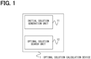
- the optimal solution calculation device 1 includes an initial solution generation unit 11 and an optimal solution search unit 12.
- the initial solution generation unit 11 generates an initial solution, which serves as an initial value to be used in the search process for the optimal solution in the optimal solution search unit 12 described later, by using an optimal solution in the previous cycle, preferably the optimal solution in the immediately preceding cycle. That is, the initial solution generation unit 11 generates an initial solution, which serves as an initial value to be used in the search process for the present optimal solution, by receiving an input of an optimal solution calculated by the optimal solution search unit 12 (described later), and using the received input of the optimal solution.
- the optimal solution search unit 12 receives the initial solution generated by the initial solution generation unit 11 as an input of an initial value of an evaluation function, calculates an optimal solution that minimizes the evaluation function, and outputs the optimal solution.
- Various methods can be used for the calculation process of the optimal solution in the optimal solution search unit 12, for example, the ABC algorithm (i.e., Artificial Bee Colony Optimization Algorithm) can be used.
- Other algorithms such as the GA algorithm (i.e., Genetic Algorithm) and the PSO algorithm (i.e., Particle Swam Optimization Algorithm) can be used.
- the optimal solution search unit 12 transmits the calculated optimal solution to the initial solution generation unit 11 as an input value of the initial solution in the next cycle, and causes the initial solution generation unit 11 to generate an initial solution in the next cycle.
- FIG. 2 shows an example of a graph of the control input X and the output Y in the model predictive control.
- the control input X is an input value to a control target 3 such as a motor
- the output Y is an output value from the control target 3.
- (a) in FIG. 2 is a prediction graph showing the relationship between the output Y, the target output value Yref, and time T, in which the prediction section is 16 cycles. The number of cycles in the prediction section can be changed depending on the control target 3 and may be any number.
- (b) in FIG. 2 is a graph showing the relationship between the control input X and time T.
- the output Y can be calculated by the following expression 1.
- the evaluation function H is expressed as the sum of the squared error with respect to the target value in the prediction section (t to t + 15 ⁇ t), and can be calculated using the following expression 2.
- e ⁇ i Yref ⁇ i ⁇ Y ⁇ i
- rand1 is random number in a range between -0.5 and 0.5
- rand2 is random number in a range between -0.5 and 0.5
- XII is the lower limit of X
- Xul is the upper limit of X.
- the initial solution generation unit 11 and the optimal solution search unit 12 repeatedly execute the above-described processes while shifting the prediction section by ⁇ t every control period ⁇ t.
- the initial solution generation unit 11 may generate, as the initial solution, a random value in the range between the upper limit value and the lower limit value of the calculation value of the evaluation function to be input to the control target 3, as in the conventional manner.
- the control system has a controller 2 and a motor which is a control target 3, and the optimal solution calculation device 1 of this embodiment is provided in the controller 2.
- the controller 2 controls the control target 3, and includes a target value generation unit 21, an optimal solution calculation device 1, a PWM 22, a driver 23, and an ACD 24.
- the target value generation unit 21 generates a target value Yref(t) of the output value of the motor, which is the control target 3.
- the target value Yref(t) is the target rotation speed of the motor.
- the optimal solution calculation device 1 has an initial solution generation unit 11 and an optimal solution searching section unit 12, similar to the above.
- the initial solution generation unit 11 generates an initial value Xinit(t) ⁇ j> using the previous optimal solution in the optimal solution search unit 12 , and transmits the generated initial value Xinit(t) ⁇ j> to the optimal solution search unit 12.
- j is a solution candidate index to be used in the processing of the optimal solution search unit 12, which will be described later.
- the optimal solution search unit 12 receives the initial value Xinit(t) ⁇ j> generated by the initial solution generation unit 11 as an input of the initial value of the evaluation function H(X), and executes a process of searching for an optimal solution.
- the optimal solution search unit 12 calculates an optimal solution Xopt(t) and transmits the optimal solution Xopt(t) to the initial solution generation unit 11 as an input value for generating an initial value Xinit(t+ ⁇ t) ⁇ j> in the next control period (t+ ⁇ t).
- the first element of the optimal solution Xopt(t) that is, Xopt_0(t) is output as the output value of the optimal solution search unit 12.
- the optimal solution search unit 12 can speed up the processing by performing parallel processing of the search for multiple solution candidates X ⁇ j> using multiple processor elements.
- a known method can be used for the parallel processing. The process for this case is shown in the flowcharts of FIGS. 5 to 7 .
- the parallel processing is shown to be performed by four processor elements PEG to PE3, the number of processor elements is not limited to four and may be any number equal to or greater than two.
- the publicly known technique shown in Non-Patent Literature 1 can also be used.
- the optimal solution searching unit 12 calculates Xopt(t) that minimizes the evaluation function H(X).
- the evaluation function H(X) is nonlinear, it is common to calculate a solution by a search-based method. Therefore, in the following explanation, the optimal solution search unit 12 also uses a search-based method.
- the optimal solution search unit 12 executes the search process LoopBody (at S120).
- a crossover process of solution candidates is performed (at S200).
- the index I1 of the solution candidates to be crossed over and the element l2 to be crossed over are randomly determined.
- An evaluation function H is calculated using the solution candidates crossed over in S200 (at S210). For example, when the solutions are crossed over, the evaluation function H(X*_l2 ⁇ j>) is calculated.
- the optimal solution search unit 12 executes the parallel processing using a plurality of processor elements PE0 to PE3 when executing the search process LoopBody.
- the processor elements PE0 to PE3 are each assigned four solution candidates X ⁇ j> equally and cause them to execute the search process LoopBody.
- the solution candidates X ⁇ 0> to X ⁇ 3> are assigned to the processor element PE0
- the solution candidates X ⁇ 4> to X ⁇ 7> are assigned to the processor element PE1
- the solution candidates X ⁇ 8> to X ⁇ 11> are assigned to the processor element PE2
- the solution candidates X ⁇ 12> to X ⁇ 15> are assigned to the processor element PE3, and each processor element is caused to execute the search process LoopBody.
- the optimal solution search unit 12 calculates the optimal solution Xopt(t) that minimizes the evaluation function H(X), and outputs the first element thereof, Xopt_0(t), as the output value of the optimal solution search unit 12.
- PWM Pulse Width Modulation 22 is a control circuit that converts into a driver switching pulse based on the value Xopt_0(t) output by the optimal solution search unit 12.
- the driver 23 converts the driver switching pulse converted by the PWM 22 into a current, inputs a control input X, and drives a motor which is the control target 3.
- the ACD 24 is a control circuit that converts the output Y from the motor as the control target 3, that is, the number of rotations of the motor, into a digital value, and outputs an output value Y_0(t).
- the ACD 24 feeds back the output value Y_0(t) as an input value of the evaluation function H in the optimal solution calculation device 1.
- the control system has the above-described configuration and controls the motor, which is the control target 3.
- control system transmits the target value Yref(t) generated by the target value generation unit 21 to the optimal solution search unit 12 of the optimal solution calculation device 1 . Furthermore, the initial solution generation unit 11 generates an initial solution Xinit(t) ⁇ j> to be used in the processing of the optimal solution search unit 12 by using the previous, preferably immediately preceding, optimal solution Xopt(t-1).
- the optimal solution search unit 12 substitutes the initial solution Xinit(t) ⁇ j> generated by the initial solution generation unit 11, the target value Yref(t) generated by the target value generation unit 21, and the previous output Y_0(t-1) into the evaluation function H, and performs a search process for the optimal solution Xopt(t) that minimizes the evaluation function H. Then, the first element Xopt_0(t) of the calculated optimal solution Xopt(t) is output as an output value. Furthermore, the optimal solution search unit 12 transmits the optimal solution Xopt(t) to the initial solution generation unit 11 so that the initial solution generation unit 11 can generate the next initial solution.
- the Xopt_0(t) output from the optimal solution calculation device 1 is converted into a driver switching pulse by the PWM 22, then, the driver switching pulse is input to the motor, which is the control target 3, as a control input X by the driver 23 to drive the motor. Then, the ACD 24 digitally converts the output Y from the motor as the control target 3, which is the motor rotation speed, outputs an output value Y_0(t), and inputs as the next input value to the optimal solution search unit 12 in the optimal solution calculation device 1.
- the motor which is the control target 3
- the motor which is the control target 3
- the optimal solution calculation device 1 of this embodiment uses each optimal solution in the prediction section calculated at time t to calculate an initial value when calculating each optimal solution in the prediction section at time t+ ⁇ t (see FIG. 3 ), thereby making it possible to shorten the calculation time by using an appropriate initial value.
- the optimal solution search unit 12 may execute processing so as to improve the convergence speed when performing the parallel processing in the processor elements PE.
- the process in this case is shown diagrammatically in FIG. 8 .
- the search process LoopBody for all solution candidates is processed equally in the processing for the solution candidates in each of the processor elements PE0 to PE3.
- ach of the processor elements PE0 to PE3 may be configured to rank the solution candidates X ⁇ j> according to the value of the evaluation function H, and to execute more search processes LoopBody for the higher ranked solution candidates than for the lower ranked solution candidates.
- the ranking can be performed by sorting the solution candidates in ascending order of the value of the evaluation function H for each solution candidate X ⁇ j>, alternatively, other methods may also be used for ranking.
- the processor element PE0 when the values H(X ⁇ 0>) to H(X ⁇ 3>) of the evaluation function H for the solution candidates X ⁇ 0> to X ⁇ 3> are sorted in ascending order, the top solution candidates are X ⁇ 0>, X ⁇ 1>, X ⁇ 2>, and X ⁇ 3>, respectively.
- the number of times the search process LoopBody is executed is set so as to increase the number of upper ranked solution candidates and decrease the number of lower ranked solution candidates. As shown in FIG.
- the search process LoopBody may be executed such that the first ranked solution candidate X ⁇ 0> is processed four times, the second ranked solution candidate X ⁇ 1> is processed twice, the third ranked solution candidate X ⁇ 2> is processed once, and the fourth ranked solution candidate X ⁇ 3> is processed once.
- an optimal solution can be acquired in a short time using the top-ranked solution candidates, and by also performing the search process for lower-ranked solution candidates, the risk of falling into a local solution can be reduced. In this way, the limited resources of the processor elements PE can be allocated efficiently.
- the number of times the search process LoopBody is executed is not limited to the above described times, and the number of times is sufficient that the upper ranked solution candidates are executed more frequently than the lower ranked solution candidates.
- control target 3 is the rotation speed of the motor.
- control target 3 is not limited to the rotation speed of the motor, and the control target 3 can be applied to various types of control targets 3.
- each value and each evaluation function in this embodiment may be a vector in addition to a scalar.
- the optimal solution calculation device of the present disclosure is not limited to the scope described in this specification, and can be arbitrarily modified within the scope of its technical concept. Furthermore, the order of each process may be changed as desired within the scope of the technical concept.
- the optimal solution calculation device of the present disclosure in a method for periodically solving an optimization problem of an evaluation function in the model predictive control, the number of searches can be reduced and the calculation time can be made shorter than in the conventional technique.
Landscapes
- Engineering & Computer Science (AREA)
- Physics & Mathematics (AREA)
- Theoretical Computer Science (AREA)
- Artificial Intelligence (AREA)
- Software Systems (AREA)
- General Physics & Mathematics (AREA)
- Evolutionary Computation (AREA)
- Health & Medical Sciences (AREA)
- General Engineering & Computer Science (AREA)
- Computing Systems (AREA)
- Mathematical Physics (AREA)
- Data Mining & Analysis (AREA)
- Computational Linguistics (AREA)
- Biophysics (AREA)
- Life Sciences & Earth Sciences (AREA)
- Bioinformatics & Computational Biology (AREA)
- Bioinformatics & Cheminformatics (AREA)
- Evolutionary Biology (AREA)
- Computer Vision & Pattern Recognition (AREA)
- Medical Informatics (AREA)
- Automation & Control Theory (AREA)
- Molecular Biology (AREA)
- Genetics & Genomics (AREA)
- General Health & Medical Sciences (AREA)
- Biomedical Technology (AREA)
- Physiology (AREA)
- Feedback Control In General (AREA)
Abstract
Description
- The present disclosure relates to an optimal solution calculation device for calculating an optimization problem in model predictive control.
- This application is based on and claims the benefits of priority of
Japanese Patent Application No. 2022-004778 filed on January 17, 2022 - In recent years, a control method called model predictive control (i.e., MPC) has been attracting attention for controlling various control devices. By using the model predictive control, the performance of the control device can be improved.
- The model predictive control is a control method that performs optimized control by solving a control input that minimizes an evaluation function indicating a control objective. The control input is an input value to a control target. There are various methods for solving the control input, including analytically solving the mathematical expression for the evaluation function, gradient methods, and search-based methods.
- However, analytically solving the mathematical expression for the evaluation function has the difficulty that the control target is restricted, and the gradient method has the difficulty that the evaluation function is restricted since it may fall into a local solution.
- As a search-based method, a technique for increasing speed by parallel processing of a plurality of processor elements for a plurality of solution candidates is known, as described in Non-Patent
Literature 1 below. - Teppei Hirotsu and Atsushi Yokoyama, "Vehicle Motion Control Algorithm for Autonomous Driving in Urban Areas and Its Implementation on Embedded ECUs", Institute of Electronics, Information and Communication Engineers Techniques Volume 115, No. 518, p1-p5, Published March 24, 2016
- The method of Non-Patent
Literature 1 is advantageous in that the method solves the difficulty in the analytically solving of the evaluation function, the gradient methods and the like since the method of Non-PatentLiterature 1 eliminates the restrictions on the evaluation function. On the other hand, in the search-based methods, when searching for a candidate solution, it is necessary to provide an initial solution, which is the initial value of the solution. However, since it is not known where the initial solution is, a random value within the range between the upper limit and the lower limit of the input value to be input to the control target is provided as the initial solution. However, by providing a random value as the initial solution, the number of searches for solution candidates increases, so that the calculation time increases. - In view of the above difficulties, the present inventor has invented an optimal solution calculation device that reduces the number of searches and shortens the calculation time compared to the conventional device.
- In order to achieve the object described above, the present disclosure employs the following measures. It is to be noted that the scope of the claims and the reference numerals in parentheses described in this section indicate the correspondence with the specific means described in the embodiments described later as one embodiment and limit the technical scope of the invention It is not something to do.
- A optimal solution calculation device according to the present disclosure is an optimal solution calculation device (1) that repeatedly calculates an optimal solution that minimizes an evaluation function having a time-varying parameter at regular intervals.
- The optimal solution calculation device includes: an initial solution generation unit (11) that generates an initial solution for providing an initial value for a search process to search for the optimal solution; and an optimal solution search unit (12) that calculates the optimal solution through the search process using the initial solution. The initial solution generation unit (11) generates the initial solution using a previous optimal solution calculated by the optimal solution search unit (12).
- Rather than assigning an initial solution using random numbers between the upper limit and the lower limit of the evaluation function as in the conventional technique, the number of searches can be reduced and the calculation time can be shortened by generating an initial solution using a previous optimal solution as in the present disclosure.
- In one embodiment of the optimal solution calculation device, the optimal solution search unit (12) assigns a solution candidate to each processor element, and executes, in parallel for each processor element, a process of repeating the search process using the assigned solution candidate a predetermined number of times.
- By performing the parallel processing in this manner, the calculation time can be shortened.
- In one embodiment of the optimal solution calculation device, the search process crosses over the solution candidates, calculates an evaluation function of the crossover solution candidates, and executes a process of updating the solution candidate when the calculation value of the evaluation function is improved.
- Although there are various methods for the search process, the method disclosed in this disclosure can be used.
- In one embodiment of the optimal solution calculation device, the optimal solution search section (12) determines the number of repetitions of the search process using a calculation value of an evaluation function of the solution candidate.
- In one embodiment of the optimal solution calculation device, the optimal solution search unit (12) determines the number of repetitions of the search process for a solution candidate having a small calculation value of the evaluation function to be greater than the number of repetitions of the search process for a solution candidate having a large calculation value of the evaluation function.
- In this way, by increasing the number of calculations of the evaluation function of a solution candidate having a better calculation value of the evaluation function, the convergence speed can be increased, the number of searches can be reduced, and the calculation time can be shortened. In an evaluation of the algorithm by the inventor, the effect was found that the calculation time was shortened by 20 to 30 percent compared to the case where the evaluation function was calculated equally for each solution candidate.
- The present disclosure may also provide a control system including any one of the above-described optimal solution calculation devices.
- By using the optimal solution calculation device of the present disclosure, in a search-based method for solving an optimization problem of an evaluation function in model predictive control, the number of searches can be reduced and the calculation time can be made shorter than in the conventional technique.
-
-
FIG. 1 is a block diagram showing an example of the configuration of an optimal solution calculation device according to an embodiment of the present disclosure. -
FIG. 2 is a diagram showing an example of a graph of a control input X and an output Y in model predictive control. -
FIG. 3 is a diagram showing a process in an initial solution generation unit according to the embodiment. -
FIG. 4 is a block diagram showing an example of a control device including an optimal solution calculation device according to the present embodiment. -
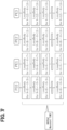
FIG. 5 is a flowchart showing an example of the overall process of the optimal solution calculation device according to the present embodiment. -
FIG. 6 is a flowchart showing an example of a processing of a search process of the optimal solution calculation device according to the present embodiment. -
FIG. 7 is a flowchart showing an example of a processing of a parallel process in the search process of the optimal solution calculation device of the present embodiment. -
FIG. 8 is a flowchart showing another example of a processing of a parallel process in the search process of the optimal solution calculation device of the present embodiment. - An example of the configuration of an optimal
solution calculation device 1 according to this embodiment is schematically shown in the block diagram ofFIG. 1 . The optimalsolution calculation device 1 of this embodiment is a device that repeatedly calculates an optimal solution that minimizes an evaluation function having a time-varying parameter at regular intervals. The optimalsolution calculation device 1 includes an initialsolution generation unit 11 and an optimalsolution search unit 12. - The initial
solution generation unit 11 generates an initial solution, which serves as an initial value to be used in the search process for the optimal solution in the optimalsolution search unit 12 described later, by using an optimal solution in the previous cycle, preferably the optimal solution in the immediately preceding cycle. That is, the initialsolution generation unit 11 generates an initial solution, which serves as an initial value to be used in the search process for the present optimal solution, by receiving an input of an optimal solution calculated by the optimal solution search unit 12 (described later), and using the received input of the optimal solution. - The optimal
solution search unit 12 receives the initial solution generated by the initialsolution generation unit 11 as an input of an initial value of an evaluation function, calculates an optimal solution that minimizes the evaluation function, and outputs the optimal solution. Various methods can be used for the calculation process of the optimal solution in the optimalsolution search unit 12, for example, the ABC algorithm (i.e., Artificial Bee Colony Optimization Algorithm) can be used. Other algorithms such as the GA algorithm (i.e., Genetic Algorithm) and the PSO algorithm (i.e., Particle Swam Optimization Algorithm) can be used. - The optimal
solution search unit 12 transmits the calculated optimal solution to the initialsolution generation unit 11 as an input value of the initial solution in the next cycle, and causes the initialsolution generation unit 11 to generate an initial solution in the next cycle. - The process of the optimal
solution calculation device 1 according to the present embodiment used in the model predictive control will now be described in more detail. Here, an evaluation function indicating a control objective in the model predictive control is defined as H, a control input that minimizes the evaluation function H is defined as X, and an output is defined as Y.FIG. 2 shows an example of a graph of the control input X and the output Y in the model predictive control. The control input X is an input value to acontrol target 3 such as a motor, and the output Y is an output value from thecontrol target 3. (a) inFIG. 2 is a prediction graph showing the relationship between the output Y, the target output value Yref, and time T, in which the prediction section is 16 cycles. The number of cycles in the prediction section can be changed depending on thecontrol target 3 and may be any number. (b) inFIG. 2 is a graph showing the relationship between the control input X and time T. - Here, as an example of prediction of the output Y, when the output Y is predicted using a difference equation, the output Y can be calculated by the
following expression 1.
- As an example, in the case of servo control in which the output Y is made to follow the target value Yref, the evaluation function H is expressed as the sum of the squared error with respect to the target value in the prediction section (t to t + 15Δt), and can be calculated using the
following expression 2.
- When the optimal solution calculated by the optimal
solution search unit 12 at time "T = t" is defined by an expression of "Xopt(t) = {Xopt_1(t), Xopt_1(t), ... , Xopt_15(t)}", the optimal solution Xopt(t+Δt) at the next time step "T = t+Δt" is predicted as the followingexpression 3.
- Therefore, the initial
solution generation unit 11 calculates the initial value of "Xinit(t+Δt) = {Xinit_0(t+Δt), Xinit_1(t+Δt), ... , Xinit_15(t+vt)}" for the optimal solution search using the followingexpression 4. Here, rand1 is random number in a range between -0.5 and 0.5, and rand2 is random number in a range between -0.5 and 0.5. XII is the lower limit of X, and Xul is the upper limit of X.
- The optimal
solution search unit 12 calculates an expression of "Xopt(t+Δt) = {Xopt_0(t+vt), Xopt_1(t+Δt), ... , Xopt_15(t+Δt)}" that minimizes the evaluation function H using the initial solution Xinit(t+Δt) calculated by the initialsolution generation unit 1, and outputs the leading element Xopt_0(t+Δt) as an output value. - The initial
solution generation unit 11 and the optimalsolution search unit 12 repeatedly execute the above-described processes while shifting the prediction section by Δt every control period Δt. - The above process is shown diagrammatically in
FIG. 3 . - Here, in the initial processing where no optimal solution exists in the optimal
solution search unit 12, the initialsolution generation unit 11 may generate, as the initial solution, a random value in the range between the upper limit value and the lower limit value of the calculation value of the evaluation function to be input to thecontrol target 3, as in the conventional manner. - Next, a process in a control system using the optimal
solution calculation device 1 of this embodiment will be described. In the following, a case where the control system controls the rotation speed of a motor will be described. A block diagram of the overall configuration of the control system in this case is shown inFIG. 4 . - In the block diagram of
FIG. 4 , the control system has acontroller 2 and a motor which is acontrol target 3, and the optimalsolution calculation device 1 of this embodiment is provided in thecontroller 2. Thecontroller 2 controls thecontrol target 3, and includes a targetvalue generation unit 21, an optimalsolution calculation device 1, aPWM 22, adriver 23, and anACD 24. - The target
value generation unit 21 generates a target value Yref(t) of the output value of the motor, which is thecontrol target 3. In the case of controlling the rotation speed of a motor, the target value Yref(t) is the target rotation speed of the motor. - The optimal
solution calculation device 1 has an initialsolution generation unit 11 and an optimal solution searchingsection unit 12, similar to the above. - The initial
solution generation unit 11 generates an initial value Xinit(t)<j> using the previous optimal solution in the optimalsolution search unit 12 , and transmits the generated initial value Xinit(t)<j> to the optimalsolution search unit 12. Here, j is a solution candidate index to be used in the processing of the optimalsolution search unit 12, which will be described later. - The optimal
solution search unit 12 receives the initial value Xinit(t)<j> generated by the initialsolution generation unit 11 as an input of the initial value of the evaluation function H(X), and executes a process of searching for an optimal solution. The optimalsolution search unit 12 inputs the initial value Xinit(t)<j> as well as a time-varying parameter "Param(t) = {Yref(t), Y_0(t)}"to the evaluation function H(X) and executes a process of searching for an optimal solution. The optimalsolution search unit 12 calculates an optimal solution Xopt(t) and transmits the optimal solution Xopt(t) to the initialsolution generation unit 11 as an input value for generating an initial value Xinit(t+Δt)<j> in the next control period (t+Δt). Here, the first element of the optimal solution Xopt(t), that is, Xopt_0(t), is output as the output value of the optimalsolution search unit 12. - When periodically solving an optimization problem in the model predictive control, the optimal
solution search unit 12 can speed up the processing by performing parallel processing of the search for multiple solution candidates X<j> using multiple processor elements. A known method can be used for the parallel processing. The process for this case is shown in the flowcharts ofFIGS. 5 to 7 . Although the parallel processing is shown to be performed by four processor elements PEG to PE3, the number of processor elements is not limited to four and may be any number equal to or greater than two. For the parallel processing in the optimalsolution search unit 12, the publicly known technique shown inNon-Patent Literature 1 can also be used. - The optimal
solution searching unit 12 calculates Xopt(t) that minimizes the evaluation function H(X). When the evaluation function H(X) is nonlinear, it is common to calculate a solution by a search-based method. Therefore, in the following explanation, the optimalsolution search unit 12 also uses a search-based method. In the search-based method, an evaluation function value H(X_j) (here, j = 0, 1, 2, . . . , m-1) is calculated based on m solution candidates X<j> (here, j = 0, 1, 2, ..., m-1) to execute a process of searching for a solution. - The optimal
solution search unit 12 substitutes the initial solution Xinit(t)<j> generated by the initialsolution generation unit 11 as an initial value of the solution candidate X<j> (at S100). Then, the search loop index iter is initialized (i.e., "variable iter = 0) (at S110). The search loop index iter is the number of times the search process LoopBody has been repeated, and a predetermined number Maxcount is set as the maximum value. - Then, the optimal
solution search unit 12 executes the search process LoopBody (at S120). - In the search process LoopBody, first, a crossover process of solution candidates is performed (at S200). In the process of the crossover for the solution candidates, for example, the index I1 of the solution candidates to be crossed over and the element l2 to be crossed over are randomly determined.
- When the solutions are not crossed over, the expression of "X*_i<j> = X_i < j >" where "i ≠ l2" and "j ≠ l1" is calculated.
- When the solutions are crossed over, the expression of "X*_l2<j> = X_l2<j> + (X_l2<l1> - X_l2<j>) x rand" where "0 ≤ rand ≤ 1" is calculated.
- The process of crossover for solution candidates is not limited to the above, and other methods can also be used.
- An evaluation function H is calculated using the solution candidates crossed over in S200 (at S210). For example, when the solutions are crossed over, the evaluation function H(X*_l2<j>) is calculated.
- When the value H(X*<j>) of the evaluation function H of the crossed-over solution candidate is smaller than the value H(X<j>) of the evaluation function H of the solution candidate before crossing over, the calculation value is defined to be improved, and the solution candidate X<j> is updated using the crossed-over solution candidate X*<j> (at S220). Then, the solution candidate index j is incremented (at S230).
- The processes from S200 to S230 are repeated until the process of crossing over and updating the solution candidates is completed for all the solution candidates (at S240).
- When the process of crossing over and updating the solution candidates is completed for all the solution candidates, the processing of the search process LoopBody is terminated, and the search loop index iter is incremented (at S130).
- Then, the processes of S120 and S130 are repeated until the repetition number of times of the search process LoopBody reaches a predetermined number of times Maxcount (at S140).
- As shown in
FIG. 7 , the optimalsolution search unit 12 executes the parallel processing using a plurality of processor elements PE0 to PE3 when executing the search process LoopBody. The processor elements PE0 to PE3 are each assigned four solution candidates X<j> equally and cause them to execute the search process LoopBody. For example, the solution candidates X<0> to X<3> are assigned to the processor element PE0, the solution candidates X<4> to X<7> are assigned to the processor element PE1, the solution candidates X<8> to X<11> are assigned to the processor element PE2, and the solution candidates X<12> to X<15> are assigned to the processor element PE3, and each processor element is caused to execute the search process LoopBody. - By executing the above-described processing, the optimal
solution search unit 12 calculates the optimal solution Xopt(t) that minimizes the evaluation function H(X), and outputs the first element thereof, Xopt_0(t), as the output value of the optimalsolution search unit 12. - PWM (i.e., Pulse Width Modulation) 22 is a control circuit that converts into a driver switching pulse based on the value Xopt_0(t) output by the optimal
solution search unit 12. - The
driver 23 converts the driver switching pulse converted by thePWM 22 into a current, inputs a control input X, and drives a motor which is thecontrol target 3. - The
ACD 24 is a control circuit that converts the output Y from the motor as thecontrol target 3, that is, the number of rotations of the motor, into a digital value, and outputs an output value Y_0(t). TheACD 24 feeds back the output value Y_0(t) as an input value of the evaluation function H in the optimalsolution calculation device 1. - The control system has the above-described configuration and controls the motor, which is the
control target 3. - The processing in the control system will be described. First, the control system transmits the target value Yref(t) generated by the target
value generation unit 21 to the optimalsolution search unit 12 of the optimalsolution calculation device 1 . Furthermore, the initialsolution generation unit 11 generates an initial solution Xinit(t)<j> to be used in the processing of the optimalsolution search unit 12 by using the previous, preferably immediately preceding, optimal solution Xopt(t-1). - Then, the optimal
solution search unit 12 substitutes the initial solution Xinit(t)<j> generated by the initialsolution generation unit 11, the target value Yref(t) generated by the targetvalue generation unit 21, and the previous output Y_0(t-1) into the evaluation function H, and performs a search process for the optimal solution Xopt(t) that minimizes the evaluation function H. Then, the first element Xopt_0(t) of the calculated optimal solution Xopt(t) is output as an output value. Furthermore, the optimalsolution search unit 12 transmits the optimal solution Xopt(t) to the initialsolution generation unit 11 so that the initialsolution generation unit 11 can generate the next initial solution. - The Xopt_0(t) output from the optimal
solution calculation device 1 is converted into a driver switching pulse by thePWM 22, then, the driver switching pulse is input to the motor, which is thecontrol target 3, as a control input X by thedriver 23 to drive the motor. Then, theACD 24 digitally converts the output Y from the motor as thecontrol target 3, which is the motor rotation speed, outputs an output value Y_0(t), and inputs as the next input value to the optimalsolution search unit 12 in the optimalsolution calculation device 1. - By repeating the above process, the motor, which is the
control target 3, can be controlled. - The optimal
solution calculation device 1 of this embodiment uses each optimal solution in the prediction section calculated at time t to calculate an initial value when calculating each optimal solution in the prediction section at time t+Δt (seeFIG. 3 ), thereby making it possible to shorten the calculation time by using an appropriate initial value. - The optimal
solution search unit 12 may execute processing so as to improve the convergence speed when performing the parallel processing in the processor elements PE. The process in this case is shown diagrammatically inFIG. 8 . - In the parallel processing of
FIG. 7 described above, the search process LoopBody for all solution candidates is processed equally in the processing for the solution candidates in each of the processor elements PE0 to PE3.Each of the processor elements PE0 to PE3 may be configured to rank the solution candidates X<j> according to the value of the evaluation function H, and to execute more search processes LoopBody for the higher ranked solution candidates than for the lower ranked solution candidates. The ranking can be performed by sorting the solution candidates in ascending order of the value of the evaluation function H for each solution candidate X<j>, alternatively, other methods may also be used for ranking. - For example, in the processor element PE0, when the values H(X<0>) to H(X<3>) of the evaluation function H for the solution candidates X<0> to X<3> are sorted in ascending order, the top solution candidates are X<0>, X<1>, X<2>, and X<3>, respectively. In this case, the number of times the search process LoopBody is executed is set so as to increase the number of upper ranked solution candidates and decrease the number of lower ranked solution candidates. As shown in
FIG. 8 , the search process LoopBody may be executed such that the first ranked solution candidate X<0> is processed four times, the second ranked solution candidate X<1> is processed twice, the third ranked solution candidate X<2> is processed once, and the fourth ranked solution candidate X<3> is processed once. In this case, it may be preferable to execute the search process LoopBody without excluding solution candidates with lower rankings. With this configuration, an optimal solution can be acquired in a short time using the top-ranked solution candidates, and by also performing the search process for lower-ranked solution candidates, the risk of falling into a local solution can be reduced. In this way, the limited resources of the processor elements PE can be allocated efficiently. The number of times the search process LoopBody is executed is not limited to the above described times, and the number of times is sufficient that the upper ranked solution candidates are executed more frequently than the lower ranked solution candidates. - In the above description, the
control target 3 is the rotation speed of the motor. However, thecontrol target 3 is not limited to the rotation speed of the motor, and thecontrol target 3 can be applied to various types of control targets 3. - In addition, each value and each evaluation function in this embodiment may be a vector in addition to a scalar.
- The optimal solution calculation device of the present disclosure is not limited to the scope described in this specification, and can be arbitrarily modified within the scope of its technical concept. Furthermore, the order of each process may be changed as desired within the scope of the technical concept.
- By using the optimal solution calculation device of the present disclosure, in a method for periodically solving an optimization problem of an evaluation function in the model predictive control, the number of searches can be reduced and the calculation time can be made shorter than in the conventional technique.
Claims (6)
- An optimal solution calculation device for repeatedly calculating an optimal solution that minimizes an evaluation function having a time-varying parameter at regular intervals, the optimal solution calculation device comprising:an initial solution generation unit that generates an initial solution for providing an initial value for a search process to search for the optimal solution; andan optimal solution search unit that calculates the optimal solution through the search process using the initial solution, wherein:
the initial solution generation unit generates the initial solution using a previous optimal solution calculated by the optimal solution search unit. - The optimal solution calculation device according to claim 1, wherein:the optimal solution search unit assigns a solution candidate to each processor element; andthe optimal solution search unit executes a process of repeating the search process using an assigned solution candidate a predetermined number of times in parallel for each processor element.
- The optimal solution calculation device according to claim 2, wherein:
the search process includes: crossing over solution candidates, calculating an evaluation function of crossed over solution candidate, and executing a process of updating the solution candidate when a calculation value of the evaluation function is improved. - The optimal solution calculation device according to claim 2 or 3, wherein:
the optimal solution search unit determines a numerical number of repetitions of the search process using a calculation value of the evaluation function for the solution candidate. - The optimal solution calculation device according to claim 2 or 3, wherein:
the optimal solution search unit determines a numerical number of repetitions of the search process for a solution candidate having a smaller calculation value of the evaluation function to be larger than a numerical number of repetitions of the search process for a solution candidate having a larger calculation value of the evaluation function. - A control system comprising:
the optimal solution calculation device according to any one of claims 1 to 5.
Applications Claiming Priority (2)
| Application Number | Priority Date | Filing Date | Title |
|---|---|---|---|
| JP2022004778 | 2022-01-17 | ||
| PCT/JP2022/048436 WO2023136150A1 (en) | 2022-01-17 | 2022-12-27 | Optimal solution calculation device |
Publications (2)
| Publication Number | Publication Date |
|---|---|
| EP4468216A1 true EP4468216A1 (en) | 2024-11-27 |
| EP4468216A4 EP4468216A4 (en) | 2025-04-30 |
Family
ID=87279122
Family Applications (1)
| Application Number | Title | Priority Date | Filing Date |
|---|---|---|---|
| EP22920666.9A Pending EP4468216A4 (en) | 2022-01-17 | 2022-12-27 | OPTIMAL SOLUTION CALCULATION DEVICE |
Country Status (5)
| Country | Link |
|---|---|
| US (1) | US20240320516A1 (en) |
| EP (1) | EP4468216A4 (en) |
| JP (1) | JP7772097B2 (en) |
| CN (1) | CN118556239A (en) |
| WO (1) | WO2023136150A1 (en) |
Families Citing this family (1)
| Publication number | Priority date | Publication date | Assignee | Title |
|---|---|---|---|---|
| JP7391213B2 (en) * | 2020-06-04 | 2023-12-04 | 三菱電機株式会社 | Optimal solution calculation device for optimization problems and optimal solution calculation method for optimization problems |
Family Cites Families (4)
| Publication number | Priority date | Publication date | Assignee | Title |
|---|---|---|---|---|
| JP2002358201A (en) * | 2001-06-01 | 2002-12-13 | Hitachi Eng Co Ltd | Parallel search method and apparatus for optimization problem |
| US9581981B2 (en) * | 2014-03-06 | 2017-02-28 | Mitsubishi Electric Corporation | Method and apparatus for preconditioned continuation model predictive control |
| JP7046740B2 (en) | 2018-07-02 | 2022-04-04 | 日立Astemo株式会社 | Predictive controller |
| JP7513868B2 (en) * | 2020-03-11 | 2024-07-10 | 富士通株式会社 | Information processing system, information processing method, and program |
-
2022
- 2022-12-27 JP JP2023573978A patent/JP7772097B2/en active Active
- 2022-12-27 WO PCT/JP2022/048436 patent/WO2023136150A1/en not_active Ceased
- 2022-12-27 EP EP22920666.9A patent/EP4468216A4/en active Pending
- 2022-12-27 CN CN202280088902.8A patent/CN118556239A/en active Pending
-
2024
- 2024-06-07 US US18/736,744 patent/US20240320516A1/en active Pending
Also Published As
| Publication number | Publication date |
|---|---|
| JPWO2023136150A1 (en) | 2023-07-20 |
| CN118556239A (en) | 2024-08-27 |
| WO2023136150A1 (en) | 2023-07-20 |
| JP7772097B2 (en) | 2025-11-18 |
| US20240320516A1 (en) | 2024-09-26 |
| EP4468216A4 (en) | 2025-04-30 |
Similar Documents
| Publication | Publication Date | Title |
|---|---|---|
| Klissarov et al. | Learnings options end-to-end for continuous action tasks | |
| US12346401B2 (en) | Combinatorial optimization system and combinatorial optimization method | |
| EP3904973A1 (en) | Device and method for controlling a robot | |
| EP4468216A1 (en) | Optimal solution calculation device | |
| Wu et al. | Effective lazy training method for deep q-network in obstacle avoidance and path planning | |
| CN108985449B (en) | Control method and device for convolutional neural network processor | |
| Jalili et al. | Chaotic biogeography algorithm for size and shape optimization of truss structures with frequency constraints | |
| JPH0934875A (en) | Quasi-optimum allocation decision method | |
| EP2898996A1 (en) | Method of controlling a robotic system and a robotic system controller for implementing this method | |
| Takayama et al. | Objective weight interval estimation using adversarial inverse reinforcement learning | |
| US11494164B2 (en) | Arithmetic processing unit, storage medium, and arithmetic processing method | |
| Tamura et al. | Learning and selection of pareto optimal policies matching user preferences | |
| Yin et al. | Adaptive traffic signal control for multi-intersection based on microscopic model | |
| Fairbank et al. | Approximating optimal control with value gradient learning | |
| JP2018037003A (en) | Global search device and program for continuous value optimization problem | |
| JP3905413B2 (en) | Robot equipment | |
| JP7427785B2 (en) | Data estimation device, method and program | |
| US20210081786A1 (en) | Information processing apparatus, non-transitory computer-readable storage medium for storing program, and information processing method | |
| Obaid et al. | Study the Neural Network Algorithms of Mathematical Numerical Optimization | |
| Hayashida et al. | Adaptive data-sharing methods for multi-agent systems using deep reinforcement learning | |
| Zajdel | Epoch-incremental reinforcement learning algorithms | |
| Vachkov et al. | Structured learning and decomposition of fuzzy models for robotic control applications | |
| CN113449461A (en) | Switch device aging equivalent method | |
| US11687616B2 (en) | Arithmetic processing apparatus, non-transitory computer-readable storage medium, and arithmetic processing method | |
| Ning et al. | A Modified Q-learning Algorithm Facing for Path Planning and Obstacle Avoidance |
Legal Events
| Date | Code | Title | Description |
|---|---|---|---|
| STAA | Information on the status of an ep patent application or granted ep patent |
Free format text: STATUS: THE INTERNATIONAL PUBLICATION HAS BEEN MADE |
|
| PUAI | Public reference made under article 153(3) epc to a published international application that has entered the european phase |
Free format text: ORIGINAL CODE: 0009012 |
|
| STAA | Information on the status of an ep patent application or granted ep patent |
Free format text: STATUS: REQUEST FOR EXAMINATION WAS MADE |
|
| 17P | Request for examination filed |
Effective date: 20240725 |
|
| AK | Designated contracting states |
Kind code of ref document: A1 Designated state(s): AL AT BE BG CH CY CZ DE DK EE ES FI FR GB GR HR HU IE IS IT LI LT LU LV MC ME MK MT NL NO PL PT RO RS SE SI SK SM TR |
|
| REG | Reference to a national code |
Ref country code: DE Ref legal event code: R079 Free format text: PREVIOUS MAIN CLASS: G06N0099000000 Ipc: G06N0003126000 |
|
| STAA | Information on the status of an ep patent application or granted ep patent |
Free format text: STATUS: EXAMINATION IS IN PROGRESS |
|
| DAV | Request for validation of the european patent (deleted) | ||
| DAX | Request for extension of the european patent (deleted) | ||
| A4 | Supplementary search report drawn up and despatched |
Effective date: 20250327 |
|
| RIC1 | Information provided on ipc code assigned before grant |
Ipc: G05B 13/04 20060101ALI20250321BHEP Ipc: G05B 13/02 20060101ALI20250321BHEP Ipc: G06N 5/01 20230101ALI20250321BHEP Ipc: G06N 3/126 20230101AFI20250321BHEP |
|
| 17Q | First examination report despatched |
Effective date: 20250409 |