EP4468193A1 - Quality metric for predictive defect model for multi-laser powder bed fusion additive manufacturing - Google Patents
Quality metric for predictive defect model for multi-laser powder bed fusion additive manufacturing Download PDFInfo
- Publication number
- EP4468193A1 EP4468193A1 EP24163911.1A EP24163911A EP4468193A1 EP 4468193 A1 EP4468193 A1 EP 4468193A1 EP 24163911 A EP24163911 A EP 24163911A EP 4468193 A1 EP4468193 A1 EP 4468193A1
- Authority
- EP
- European Patent Office
- Prior art keywords
- additive manufacturing
- metric
- instruction
- scalar metric
- nodes
- Prior art date
- Legal status (The legal status is an assumption and is not a legal conclusion. Google has not performed a legal analysis and makes no representation as to the accuracy of the status listed.)
- Granted
Links
Images


Classifications
-
- G—PHYSICS
- G06—COMPUTING OR CALCULATING; COUNTING
- G06F—ELECTRIC DIGITAL DATA PROCESSING
- G06F30/00—Computer-aided design [CAD]
- G06F30/20—Design optimisation, verification or simulation
-
- B—PERFORMING OPERATIONS; TRANSPORTING
- B29—WORKING OF PLASTICS; WORKING OF SUBSTANCES IN A PLASTIC STATE IN GENERAL
- B29C—SHAPING OR JOINING OF PLASTICS; SHAPING OF MATERIAL IN A PLASTIC STATE, NOT OTHERWISE PROVIDED FOR; AFTER-TREATMENT OF THE SHAPED PRODUCTS, e.g. REPAIRING
- B29C64/00—Additive manufacturing, i.e. manufacturing of three-dimensional [3D] objects by additive deposition, additive agglomeration or additive layering, e.g. by 3D printing, stereolithography or selective laser sintering
- B29C64/30—Auxiliary operations or equipment
- B29C64/386—Data acquisition or data processing for additive manufacturing
- B29C64/393—Data acquisition or data processing for additive manufacturing for controlling or regulating additive manufacturing processes
-
- B—PERFORMING OPERATIONS; TRANSPORTING
- B22—CASTING; POWDER METALLURGY
- B22F—WORKING METALLIC POWDER; MANUFACTURE OF ARTICLES FROM METALLIC POWDER; MAKING METALLIC POWDER; APPARATUS OR DEVICES SPECIALLY ADAPTED FOR METALLIC POWDER
- B22F10/00—Additive manufacturing of workpieces or articles from metallic powder
- B22F10/20—Direct sintering or melting
- B22F10/28—Powder bed fusion, e.g. selective laser melting [SLM] or electron beam melting [EBM]
-
- B—PERFORMING OPERATIONS; TRANSPORTING
- B22—CASTING; POWDER METALLURGY
- B22F—WORKING METALLIC POWDER; MANUFACTURE OF ARTICLES FROM METALLIC POWDER; MAKING METALLIC POWDER; APPARATUS OR DEVICES SPECIALLY ADAPTED FOR METALLIC POWDER
- B22F10/00—Additive manufacturing of workpieces or articles from metallic powder
- B22F10/30—Process control
- B22F10/38—Process control to achieve specific product aspects, e.g. surface smoothness, density, porosity or hollow structures
-
- B—PERFORMING OPERATIONS; TRANSPORTING
- B22—CASTING; POWDER METALLURGY
- B22F—WORKING METALLIC POWDER; MANUFACTURE OF ARTICLES FROM METALLIC POWDER; MAKING METALLIC POWDER; APPARATUS OR DEVICES SPECIALLY ADAPTED FOR METALLIC POWDER
- B22F10/00—Additive manufacturing of workpieces or articles from metallic powder
- B22F10/80—Data acquisition or data processing
-
- B—PERFORMING OPERATIONS; TRANSPORTING
- B22—CASTING; POWDER METALLURGY
- B22F—WORKING METALLIC POWDER; MANUFACTURE OF ARTICLES FROM METALLIC POWDER; MAKING METALLIC POWDER; APPARATUS OR DEVICES SPECIALLY ADAPTED FOR METALLIC POWDER
- B22F12/00—Apparatus or devices specially adapted for additive manufacturing; Auxiliary means for additive manufacturing; Combinations of additive manufacturing apparatus or devices with other processing apparatus or devices
- B22F12/40—Radiation means
- B22F12/44—Radiation means characterised by the configuration of the radiation means
- B22F12/45—Two or more
-
- B—PERFORMING OPERATIONS; TRANSPORTING
- B33—ADDITIVE MANUFACTURING TECHNOLOGY
- B33Y—ADDITIVE MANUFACTURING, i.e. MANUFACTURING OF THREE-DIMENSIONAL [3D] OBJECTS BY ADDITIVE DEPOSITION, ADDITIVE AGGLOMERATION OR ADDITIVE LAYERING, e.g. BY 3D PRINTING, STEREOLITHOGRAPHY OR SELECTIVE LASER SINTERING
- B33Y10/00—Processes of additive manufacturing
-
- B—PERFORMING OPERATIONS; TRANSPORTING
- B33—ADDITIVE MANUFACTURING TECHNOLOGY
- B33Y—ADDITIVE MANUFACTURING, i.e. MANUFACTURING OF THREE-DIMENSIONAL [3D] OBJECTS BY ADDITIVE DEPOSITION, ADDITIVE AGGLOMERATION OR ADDITIVE LAYERING, e.g. BY 3D PRINTING, STEREOLITHOGRAPHY OR SELECTIVE LASER SINTERING
- B33Y50/00—Data acquisition or data processing for additive manufacturing
-
- B—PERFORMING OPERATIONS; TRANSPORTING
- B33—ADDITIVE MANUFACTURING TECHNOLOGY
- B33Y—ADDITIVE MANUFACTURING, i.e. MANUFACTURING OF THREE-DIMENSIONAL [3D] OBJECTS BY ADDITIVE DEPOSITION, ADDITIVE AGGLOMERATION OR ADDITIVE LAYERING, e.g. BY 3D PRINTING, STEREOLITHOGRAPHY OR SELECTIVE LASER SINTERING
- B33Y50/00—Data acquisition or data processing for additive manufacturing
- B33Y50/02—Data acquisition or data processing for additive manufacturing for controlling or regulating additive manufacturing processes
-
- G—PHYSICS
- G06—COMPUTING OR CALCULATING; COUNTING
- G06F—ELECTRIC DIGITAL DATA PROCESSING
- G06F30/00—Computer-aided design [CAD]
- G06F30/20—Design optimisation, verification or simulation
- G06F30/23—Design optimisation, verification or simulation using finite element methods [FEM] or finite difference methods [FDM]
-
- G—PHYSICS
- G06—COMPUTING OR CALCULATING; COUNTING
- G06F—ELECTRIC DIGITAL DATA PROCESSING
- G06F2113/00—Details relating to the application field
- G06F2113/10—Additive manufacturing, e.g. three-dimensional [3D] printing
-
- G—PHYSICS
- G06—COMPUTING OR CALCULATING; COUNTING
- G06F—ELECTRIC DIGITAL DATA PROCESSING
- G06F2119/00—Details relating to the type or aim of the analysis or the optimisation
- G06F2119/18—Manufacturability analysis or optimisation for manufacturability
Definitions
- a further embodiment of any of the foregoing embodiments may additionally and/or alternatively include the scalar metric describes the overall quality of the part fabricated by powder bed fusion additive manufacturing with respect to predicted defects.
- a further embodiment of any of the foregoing embodiments may additionally and/or alternatively include the system for additive manufacturing further comprising an instruction to discretize the part in space in preparation for determining the scalar metric.
- a further embodiment of any of the foregoing embodiments may additionally and/or alternatively include the system for additive manufacturing further comprising an instruction to discretize the part by a set of nodes used for a finite difference computation.
- a further embodiment of any of the foregoing embodiments may additionally and/or alternatively include the system for additive manufacturing further comprising an instruction to compute the scalar metric from discretizations, such as finite volume or finite element.
- a further embodiment of any of the foregoing embodiments may additionally and/or alternatively include the system for additive manufacturing further comprising an instruction to compute the scalar metric as a sum of a total number of nodes predicted to contain defects divided by a total number of nodes in the part.
- a further embodiment of any of the foregoing embodiments may additionally and/or alternatively include the system for additive manufacturing further comprising an instruction to determine the scalar metric used to interface with the external optimization framework, wherein the scalar metric comprises the ratio of a number of defected nodes to total nodes used in the defect model.
- a further embodiment of any of the foregoing embodiments may additionally and/or alternatively include the system for additive manufacturing further comprising an instruction to determine the defect quality metric as a ratio of a sum of fractional defect density at each defected node to total nodes used in the defect model.
- a further embodiment of any of the foregoing embodiments may additionally and/or alternatively include the system for additive manufacturing further comprising an instruction to introduce a location criticality weighting coefficient configured to discourage defects in critical regions of a part.
- a further embodiment of any of the foregoing embodiments may additionally and/or alternatively include the location criticality weighting coefficient is proportional to stress.
- a process for an external optimization framework utilizing a defect model for multi-laser additive manufacturing of a part comprising determining a scalar metric for the part; employing the scalar metric in the defect model; providing at least one output from the defect model to the external optimization framework; and optimizing the powder bed fusion additive manufacturing process for the part with the external optimization framework.
- Particular embodiments may include at least one of, or a plurality of, the following optional features. These features may be included separately from each other or in combination with each other, unless specified otherwise.
- a further embodiment of any of the foregoing embodiments may additionally and/or alternatively include the scalar metric describes the overall quality of the part fabricated by powder bed fusion additive manufacturing with respect to predicted defects.
- a further embodiment of any of the foregoing embodiments may additionally and/or alternatively include the process further comprising configuring the scalar metric as a single number employed as an objective or as a constraint in the optimization of the powder bed fusion additive manufacturing process for the part.
- a further embodiment of any of the foregoing embodiments may additionally and/or alternatively include the process further comprising discretizing the part in space in preparation for determining the scalar metric.
- a further embodiment of any of the foregoing embodiments may additionally and/or alternatively include the process further comprising discretizing the part by a set of nodes used for a finite difference computation.
- a further embodiment of any of the foregoing embodiments may additionally and/or alternatively include the process further comprising computing the scalar metric as a sum of a total number of nodes predicted to contain defects divided by a total number of nodes in the part.
- a further embodiment of any of the foregoing embodiments may additionally and/or alternatively include the process further comprising determining the scalar metric used to interface with the external optimization framework, wherein the scalar metric comprises the ratio of a number of defected nodes to total nodes used in the defect model.
- a further embodiment of any of the foregoing embodiments may additionally and/or alternatively include the process further comprising determining the defect quality metric as a ratio of a sum of fractional defect density at each defected node to total nodes used in the defect model.
- a further embodiment of any of the foregoing embodiments may additionally and/or alternatively include the process further comprising introducing a location criticality weighting coefficient configured to discourage defects in critical regions of a part, wherein the location criticality weighting coefficient is proportional to stress.
- FIG. 1 schematically illustrates an additive manufacturing machine 10, such as a laser powder bed fusion additive manufacturing (PBFAM) machine.
- the powder bed fusion machine can be an electron beam powder bed fusion machine.
- the exemplary additive manufacturing machine 10 includes a manufacturing chamber 12 with a platform 14 upon which a part 16 (alternatively referred to as a work piece) is additively manufactured.
- a controller 18 is connected to the chamber 12 and controls the additive manufacturing process according to any known additive manufacturing control system.
- controller 18 includes a processor 20 that receives and interprets input operations to define a sequence of the additive manufacturing.
- operations refers to instructions specifying operational conditions for one or more step in an additive manufacturing process.
- the controller 18 can, in some examples, include user interface devices such as a keyboard and view screen. In alternative examples, the controller 18 can include a wireless or wired communication apparatus for communicating with a remote user input device such as a PC.
- the controller 18 receives a desired additive manufacturing operation, or sequence of operations, and evaluates the entered operation(s) to determine if the resultant part 16 will be free of flaws.
- free of flaws, or flaw free refers to a part 16 or workpiece with no flaws causing the part or workpiece to fall outside of predefined flaw tolerance.
- the predefined tolerances can include an amount of unmelt, a surface roughness, or any other measurable property of the part 16.
- factors impacting the output parameters can include material properties, environmental conditions, laser power, laser speed, or any other factors. While described and illustrated herein as a component of a laser powder bed fusion additive manufacturing machine, the software configuration and operations can, in some examples, be embodied as a distinct software program independent of the additive manufacturing machine or included within any other type of additive manufacturing machine.
- a build strategy is parsed and/or specifically prescribed scan vectors are used to create stripe and hatch definitions in each layer of the build.
- the additive build is simulated layer-by-layer.
- the output is a map in build parameter space (e.g. laser power, laser speed, layer thickness, etc.).
- the map is partitioned into different regions reflecting whether flaws are present: lack of fusion, keyholing, the flaw-free "good” zone, etc.
- a process map is optionally location-specific and dependent upon geometry. If the entirety of a part is in the "good" zone of the process map, it is predicted to be flaw-free.
- a technician can generate a part 16, or design a sequence of operations to generate a part 16, without requiring substantial empirical prototyping to be performed. This, in turn, allows the part to be designed faster, and with less expense, due to the substantially reduced number of physical iterations performed.
- the part 16 is shown as being created by a single laser and multiple lasers.
- the part 16 shown on the left side of Fig. 2 is laid down by use of a single laser 24.
- the whole part 16 is assigned to the single laser 24.
- the part 16 shown to the right side of Fig. 2 is assigned to multiple lasers 24.
- the multi-laser fusion is configured to increase the rate at which the part 16 can be built.
- the single laser fusion can have a different set of heat flux, interlayer dwell time, underlying temperature than the multi-laser fusion configuration.
- the part 16 can be divided into multiple regions 26, such as laser 1 region, laser 2 region and laser 3 region, as shown. Each region 26 can be processed by the different lasers 24. So, each region may have a different set of heat flux, interlayer dwell time, underlying temperature, and the like.
- the multi-laser arrangement can include laser interface 28 along the common boundaries of the regions 26. It is possible to create a laser interaction zone 30 near these interfaces 28.
- the lasers 24 can create conditions that cause interaction between the adjoining lasers 24.
- the defect model 32 can generate a time-location map for lasers 24 using the inputs provided by the user including scan speed, hatch distance and stripe angle. The user can also provide delay time for the lasers 24 if there is a lag between the lasers 24 to start a layer.
- the defect model 32 can employ a multi-laser code which uses a global simulation domain rather than a local simulation domain used by an alternative defect code.
- An analysis tool 36 operates the defect model 32 to produce the necessary outputs utilized by the additive manufacturing machine 10.
- a scalar metric 38 can be employed as an objective or constraint in a process for the defect model 32 of the analysis tool 36.
- the scalar metric 38 can be employed to determine optimal additive manufacturing build parameters or to determine optimal geometry for the part 16.
- the defect model 32 can utilize the scalar metric 38 and produce an output 39 to the external optimization framework 34.
- the external optimization framework 34 can optimize the powder bed fusion additive manufacturing process.
- the external optimization framework can employ additional physics-based model(s) 40 as an additional avenue to optimize the powder bed fusion additive manufacturing process.
- an exemplary part 16 is shown having defects 42.
- the part 16 can be any part such that can be manufactured by laser powder bed fusion additive manufacturing.
- the part 16 is shown as a 3D structure having random defects 42.
- the defects 42 can be a lack of fusion of the powder bed material by the laser, keyholes, voids, porosity, layer discontinuities, and/or other imperfections associated with powder bed fusion additive manufacturing.
- the scalar metric 38 describes the overall quality of a part 16 fabricated by powder bed fusion additive manufacturing with respect to predicted defects 42, such as porosity.
- the scalar metric 38 is a single number which allows the metric to be used as an objective or as a constraint.
- the part 16 In order to compute the metric 38, the part 16 must be discretized in space (i.e., divided into smaller volumes).
- One embodiment can include the part 16 being discretized by a set of nodes 44 used for finite difference computation.
- the use of the metric can be utilized by the defect model 32.
- the metric 38 can be computed from other discretizations, such as finite volume or finite element. In that case, the language may be adapted to that discretization, i.e.; referring to volume or elements rather than nodes 44.
- the most straightforward way to compute the quality metric 38 is to sum the total number of nodes 46 predicted to contain defects 42 and divide by the total number of nodes 44 in the part 16.
- the metric 38 can be extended to sum defect density predicted at defected nodes 46.
- the metric 38 may be extended to factor in location criticality through the use of a weighting factor. Locations may be weighted based on stress or other phenomenon that influences part life or performance.
- the defect quality metric 38 can be used to interface with the external optimization framework 34 and can be the ratio of the number of defected (finite difference) nodes 46 to total nodes 44 used in the defect model 32.
- the defect quality metric 38 can be a ratio of the sum of fractional defect 42 density at each defected (finite difference) nodes 46 to total nodes 44 used in the defect model 32.
- the defect quality metric 38 can introduce a location criticality weighting coefficient c g to discourage defects 42 in more critical regions of a part 16.
- a location criticality weighting coefficient c g to discourage defects 42 in more critical regions of a part 16.
- FIG. 5 an exemplary part such as an additively manufactured blade/vane 48 is shown.
- the blade or vane 48 can include a root portion 50, an airfoil portion 52 and a tip portion 54.
- the stress in the blade/vane 48 is considered higher proximate the root portion 50 than at the tip portion 54 for a normal operating condition.
- the part criticality weighting factor is larger at the root of the blade where stress is highest.
- the part criticality weighting factor c g may be proportional to stress. c g ⁇ ⁇
- a technical advantage of the disclosed process can include the ability to use a scalar metric to optimize additive manufacturing parameters and part geometries.
- Another technical advantage of the process can include application to multi-laser powder bed fusion additive manufacturing.
- Another technical advantage of the process can include providing a higher quality multi-laser powder bed fusion additive manufacturing.
- Another technical advantage of the process can include faster multi-laser powder bed fusion additive manufacturing processing.
- Another technical advantage of the process can include optimized laser path planning to maximize laser on-time while minimizing laser interaction and therefore defect production.
- Another technical advantage of the process can include helping engineers and designers understand and develop multi-laser powder bed fusion additive manufacturing processes to increase rate of production and build large size parts.
- Another technical advantage of the process can include minimizing the costly and time-consuming trial and error practices which are currently used for qualifying additive manufacturing parts.
- Another technical advantage of the process can include information obtained from this predictive model can be utilized to additively manufacture high quality parts which in turn minimizes post-build operations in the production process chain.
Landscapes
- Engineering & Computer Science (AREA)
- Chemical & Material Sciences (AREA)
- Materials Engineering (AREA)
- Manufacturing & Machinery (AREA)
- Physics & Mathematics (AREA)
- Theoretical Computer Science (AREA)
- Health & Medical Sciences (AREA)
- General Health & Medical Sciences (AREA)
- Toxicology (AREA)
- Computer Hardware Design (AREA)
- Evolutionary Computation (AREA)
- Geometry (AREA)
- General Engineering & Computer Science (AREA)
- General Physics & Mathematics (AREA)
- Optics & Photonics (AREA)
- Mechanical Engineering (AREA)
- Automation & Control Theory (AREA)
- Plasma & Fusion (AREA)
- Powder Metallurgy (AREA)
Abstract
Description
- The present disclosure relates generally to additive manufacturing, and more specifically to a process for determining a scalar metric that describes the overall quality of a part fabricated by additive manufacturing operations.
- Additive manufacturing is a process that is utilized to create components by applying sequential material layers, with each layer being applied to the previous material layer. As a result of the iterative, trial and error, construction process, multiple different parameters affect whether an end product created using the additive manufacturing process includes flaws or is within acceptable tolerances of a given part. Typically, components created using an additive manufacturing process are designed iteratively, by adjusting one or more parameters each iteration and examining the results to determine if the results have the required quality.
- Multi-laser additive manufacturing (AM) technology is a promising process to increase allowable part size and rate of production. However, multiple lasers in additive systems could add further complications and challenges to material quality. There is no known tool to predict defect formation and dependency to process parameters for multi-laser applications. It is known how to predict defect type, density and location at the part level under a single laser operation. An example can be the teaching in
US patent 10,252,512 - What is not well known is the determination of a quality metric associated with predicted defects in parts. Multi-laser additive manufacturing, owing to multiple lasers is capable of producing different types of defects such as lack of fusion and keyhole porosity. As the number of lasers acting simultaneously increases, the likelihood of multi-laser interaction goes up.
- What is needed is a process for determining a quality metric associated with types of defects in components produced by multi-laser powder bed fusion additive manufacturing (PBFAM).
- In accordance with the present disclosure, there is provided a system comprising a computer readable storage device readable by the system, tangibly embodying a program having a set of instructions executable by the system to perform the following steps for predicting defects in powder bed fusion additive manufacturing process for a part, the set of instructions comprising an instruction to determine a scalar metric for the part; an instruction to employ the scalar metric in a defect model; an instruction to provide at least one output from the defect model to an external optimization framework; and an instruction to optimize the powder bed fusion additive manufacturing process for the part with the external optimization framework.
- Particular embodiments may include at least one of, or a plurality of, the following optional features. These features may be included separately from each other or in combination with each other, unless specified otherwise.
- A further embodiment of any of the foregoing embodiments may additionally and/or alternatively include the scalar metric describes the overall quality of the part fabricated by powder bed fusion additive manufacturing with respect to predicted defects.
- A further embodiment of any of the foregoing embodiments may additionally and/or alternatively include the scalar metric is configured as a single number employed as an objective or as a constraint in the optimization of the powder bed fusion additive manufacturing process for the part.
- A further embodiment of any of the foregoing embodiments may additionally and/or alternatively include the system for additive manufacturing further comprising an instruction to discretize the part in space in preparation for determining the scalar metric.
- A further embodiment of any of the foregoing embodiments may additionally and/or alternatively include the system for additive manufacturing further comprising an instruction to discretize the part by a set of nodes used for a finite difference computation.
- A further embodiment of any of the foregoing embodiments may additionally and/or alternatively include the system for additive manufacturing further comprising an instruction to compute the scalar metric from discretizations, such as finite volume or finite element.
- A further embodiment of any of the foregoing embodiments may additionally and/or alternatively include the system for additive manufacturing further comprising an instruction to compute the scalar metric as a sum of a total number of nodes predicted to contain defects divided by a total number of nodes in the part.
- A further embodiment of any of the foregoing embodiments may additionally and/or alternatively include the system for additive manufacturing further comprising an instruction to determine the scalar metric used to interface with the external optimization framework, wherein the scalar metric comprises the ratio of a number of defected nodes to total nodes used in the defect model.
- A further embodiment of any of the foregoing embodiments may additionally and/or alternatively include the system for additive manufacturing further comprising an instruction to determine the defect quality metric as a ratio of a sum of fractional defect density at each defected node to total nodes used in the defect model.
- A further embodiment of any of the foregoing embodiments may additionally and/or alternatively include the system for additive manufacturing further comprising an instruction to introduce a location criticality weighting coefficient configured to discourage defects in critical regions of a part.
- A further embodiment of any of the foregoing embodiments may additionally and/or alternatively include the location criticality weighting coefficient is proportional to stress.
- In accordance with the present disclosure, there is provided a process for an external optimization framework utilizing a defect model for multi-laser additive manufacturing of a part comprising determining a scalar metric for the part; employing the scalar metric in the defect model; providing at least one output from the defect model to the external optimization framework; and optimizing the powder bed fusion additive manufacturing process for the part with the external optimization framework.
- Particular embodiments may include at least one of, or a plurality of, the following optional features. These features may be included separately from each other or in combination with each other, unless specified otherwise.
- A further embodiment of any of the foregoing embodiments may additionally and/or alternatively include the scalar metric describes the overall quality of the part fabricated by powder bed fusion additive manufacturing with respect to predicted defects.
- A further embodiment of any of the foregoing embodiments may additionally and/or alternatively include the process further comprising configuring the scalar metric as a single number employed as an objective or as a constraint in the optimization of the powder bed fusion additive manufacturing process for the part.
- A further embodiment of any of the foregoing embodiments may additionally and/or alternatively include the process further comprising discretizing the part in space in preparation for determining the scalar metric.
- A further embodiment of any of the foregoing embodiments may additionally and/or alternatively include the process further comprising discretizing the part by a set of nodes used for a finite difference computation.
- A further embodiment of any of the foregoing embodiments may additionally and/or alternatively include the process further comprising computing the scalar metric as a sum of a total number of nodes predicted to contain defects divided by a total number of nodes in the part.
- A further embodiment of any of the foregoing embodiments may additionally and/or alternatively include the process further comprising determining the scalar metric used to interface with the external optimization framework, wherein the scalar metric comprises the ratio of a number of defected nodes to total nodes used in the defect model.
- A further embodiment of any of the foregoing embodiments may additionally and/or alternatively include the process further comprising determining the defect quality metric as a ratio of a sum of fractional defect density at each defected node to total nodes used in the defect model.
- A further embodiment of any of the foregoing embodiments may additionally and/or alternatively include the process further comprising introducing a location criticality weighting coefficient configured to discourage defects in critical regions of a part, wherein the location criticality weighting coefficient is proportional to stress.
- Other details of the process are set forth in the following detailed description and the accompanying drawings wherein like reference numerals depict like elements.
-
Fig. 1 is a schematic representation of an exemplary additive manufacturing machine. -
Fig. 2 is a schematic representation of a part created by a single laser along side the part created by multiple lasers. -
Fig. 3 is a schematic representation of interaction between a laser powder bed fusion defect model with external optimization framework. -
Fig. 4 is a schematic representation of an exemplary part with defects. -
Fig. 5 is a schematic representation of an exemplary blade. - Referring now to
Fig. 1 , schematically illustrates anadditive manufacturing machine 10, such as a laser powder bed fusion additive manufacturing (PBFAM) machine. In alternate examples, the powder bed fusion machine can be an electron beam powder bed fusion machine. The exemplaryadditive manufacturing machine 10 includes amanufacturing chamber 12 with aplatform 14 upon which a part 16 (alternatively referred to as a work piece) is additively manufactured. Acontroller 18 is connected to thechamber 12 and controls the additive manufacturing process according to any known additive manufacturing control system. - Included within the
controller 18 is aprocessor 20 that receives and interprets input operations to define a sequence of the additive manufacturing. As utilized herein "operations" refers to instructions specifying operational conditions for one or more step in an additive manufacturing process. Thecontroller 18 can, in some examples, include user interface devices such as a keyboard and view screen. In alternative examples, thecontroller 18 can include a wireless or wired communication apparatus for communicating with a remote user input device such as a PC. - Also included in the
controller 18 is amemory 22. In some examples, thecontroller 18 receives a desired additive manufacturing operation, or sequence of operations, and evaluates the entered operation(s) to determine if theresultant part 16 will be free of flaws. For the purposes of the instant disclosure, free of flaws, or flaw free, refers to apart 16 or workpiece with no flaws causing the part or workpiece to fall outside of predefined flaw tolerance. By way of example, the predefined tolerances can include an amount of unmelt, a surface roughness, or any other measurable property of thepart 16. By way of example, factors impacting the output parameters can include material properties, environmental conditions, laser power, laser speed, or any other factors. While described and illustrated herein as a component of a laser powder bed fusion additive manufacturing machine, the software configuration and operations can, in some examples, be embodied as a distinct software program independent of the additive manufacturing machine or included within any other type of additive manufacturing machine. - A build strategy is parsed and/or specifically prescribed scan vectors are used to create stripe and hatch definitions in each layer of the build. The additive build is simulated layer-by-layer. The output is a map in build parameter space (e.g. laser power, laser speed, layer thickness, etc.). The map is partitioned into different regions reflecting whether flaws are present: lack of fusion, keyholing, the flaw-free "good" zone, etc. A process map is optionally location-specific and dependent upon geometry. If the entirety of a part is in the "good" zone of the process map, it is predicted to be flaw-free.
- By using the defined process map, a technician can generate a
part 16, or design a sequence of operations to generate apart 16, without requiring substantial empirical prototyping to be performed. This, in turn, allows the part to be designed faster, and with less expense, due to the substantially reduced number of physical iterations performed. - Referring also to
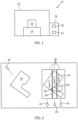
Fig. 2 , thepart 16 is shown as being created by a single laser and multiple lasers. Thepart 16 shown on the left side ofFig. 2 is laid down by use of asingle laser 24. Thewhole part 16 is assigned to thesingle laser 24. Thepart 16 shown to the right side ofFig. 2 is assigned tomultiple lasers 24. The multi-laser fusion is configured to increase the rate at which thepart 16 can be built. The single laser fusion can have a different set of heat flux, interlayer dwell time, underlying temperature than the multi-laser fusion configuration. - With multi-laser fusion processes, the
part 16 can be divided intomultiple regions 26, such aslaser 1 region,laser 2 region andlaser 3 region, as shown. Eachregion 26 can be processed by thedifferent lasers 24. So, each region may have a different set of heat flux, interlayer dwell time, underlying temperature, and the like. - In
Fig. 2 , the multi-laser arrangement can includelaser interface 28 along the common boundaries of theregions 26. It is possible to create alaser interaction zone 30 near theseinterfaces 28. Thelasers 24 can create conditions that cause interaction between the adjoininglasers 24. - Referring also to
Fig. 3 a diagram of a laser powder bedfusion defect model 32 withexternal optimization framework 34 is shown. In an exemplary embodiment, thedefect model 32 can generate a time-location map forlasers 24 using the inputs provided by the user including scan speed, hatch distance and stripe angle. The user can also provide delay time for thelasers 24 if there is a lag between thelasers 24 to start a layer. Thedefect model 32 can employ a multi-laser code which uses a global simulation domain rather than a local simulation domain used by an alternative defect code. Ananalysis tool 36 operates thedefect model 32 to produce the necessary outputs utilized by theadditive manufacturing machine 10. A scalar metric 38 can be employed as an objective or constraint in a process for thedefect model 32 of theanalysis tool 36. The scalar metric 38 can be employed to determine optimal additive manufacturing build parameters or to determine optimal geometry for thepart 16. Thedefect model 32 can utilize thescalar metric 38 and produce anoutput 39 to theexternal optimization framework 34. Theexternal optimization framework 34 can optimize the powder bed fusion additive manufacturing process. - In an exemplary embodiment, the external optimization framework can employ additional physics-based model(s) 40 as an additional avenue to optimize the powder bed fusion additive manufacturing process.
- Referring also to
Fig. 4 , anexemplary part 16 is shown havingdefects 42. Thepart 16 can be any part such that can be manufactured by laser powder bed fusion additive manufacturing. Thepart 16 is shown as a 3D structure havingrandom defects 42. Thedefects 42 can be a lack of fusion of the powder bed material by the laser, keyholes, voids, porosity, layer discontinuities, and/or other imperfections associated with powder bed fusion additive manufacturing. - Optimizing additive manufacturing build parameters in
parts 16 with complex geometries can be challenging. Overall optimization of apart 16 may seek to minimize the number or amount of porosity/defects 42 and/or drive them to regions of thepart 16 with low criticality. Thescalar metric 38 describes the overall quality of apart 16 fabricated by powder bed fusion additive manufacturing with respect to predicteddefects 42, such as porosity. Thescalar metric 38 is a single number which allows the metric to be used as an objective or as a constraint. - In order to compute the metric 38, the
part 16 must be discretized in space (i.e., divided into smaller volumes). One embodiment can include thepart 16 being discretized by a set ofnodes 44 used for finite difference computation. The use of the metric can be utilized by thedefect model 32. The metric 38 can be computed from other discretizations, such as finite volume or finite element. In that case, the language may be adapted to that discretization, i.e.; referring to volume or elements rather thannodes 44. - In an exemplary embodiment, the most straightforward way to compute the
quality metric 38 is to sum the total number ofnodes 46 predicted to containdefects 42 and divide by the total number ofnodes 44 in thepart 16. In an exemplary embodiment, the metric 38 can be extended to sum defect density predicted at defectednodes 46. In an exemplary embodiment, the metric 38 may be extended to factor in location criticality through the use of a weighting factor. Locations may be weighted based on stress or other phenomenon that influences part life or performance. - The
defect quality metric 38 can be used to interface with theexternal optimization framework 34 and can be the ratio of the number of defected (finite difference)nodes 46 tototal nodes 44 used in thedefect model 32. - The quality
metric q g 38 can be expressed as:
where pg : defect at grid point g used in the defect model (binary value); and Ng : number of grid points. - In an exemplary embodiment, the
defect quality metric 38 can be a ratio of the sum offractional defect 42 density at each defected (finite difference)nodes 46 tototal nodes 44 used in thedefect model 32. - The quality
metric q g 38 can be expressed as:

where dg : fractional defect density predicted by defect model; and Ng : number of grid points. - In an exemplary embodiment, the
defect quality metric 38 can introduce a location criticality weighting coefficient cg to discouragedefects 42 in more critical regions of apart 16. Referring also toFig. 5 , an exemplary part such as an additively manufactured blade/vane 48 is shown. The blade orvane 48 can include aroot portion 50, anairfoil portion 52 and atip portion 54. - In a first version with a location criticality weighting coefficient cg, the quality
metric q g 38 can be expressed as:

where pg : defect at grid point g used in the defect model (binary value); cg : part location criticality weighting coefficient; and Ng : number of grid points. - In a second version with a location criticality weighting coefficient cg, the quality
metric q g 38 can be expressed as:
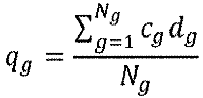
where dg : fractional defect density predicted by defect model; cg : part location criticality weighting coefficient; and Ng : number of grid points. - The stress in the blade/
vane 48 is considered higher proximate theroot portion 50 than at thetip portion 54 for a normal operating condition. The part criticality weighting factor is larger at the root of the blade where stress is highest.
- The part criticality weighting factor cg may be proportional to stress.

- A technical advantage of the disclosed process can include the ability to use a scalar metric to optimize additive manufacturing parameters and part geometries.
- Another technical advantage of the process can include application to multi-laser powder bed fusion additive manufacturing.
- Another technical advantage of the process can include providing a higher quality multi-laser powder bed fusion additive manufacturing.
- Another technical advantage of the process can include faster multi-laser powder bed fusion additive manufacturing processing.
- Another technical advantage of the process can include optimized laser path planning to maximize laser on-time while minimizing laser interaction and therefore defect production.
- Another technical advantage of the process can include helping engineers and designers understand and develop multi-laser powder bed fusion additive manufacturing processes to increase rate of production and build large size parts.
- Another technical advantage of the process can include minimizing the costly and time-consuming trial and error practices which are currently used for qualifying additive manufacturing parts.
- Another technical advantage of the process can include information obtained from this predictive model can be utilized to additively manufacture high quality parts which in turn minimizes post-build operations in the production process chain.
- There has been provided a process. While the process has been described in the context of specific embodiments thereof, other unforeseen alternatives, modifications, and variations may become apparent to those skilled in the art having read the foregoing description. Accordingly, it is intended to embrace those alternatives, modifications, and variations which fall within the broad scope of the appended claims.
Claims (15)
- A system comprising a computer readable storage device readable by the system, tangibly embodying a program having a set of instructions executable by the system to perform the following steps for predicting defects in powder bed fusion additive manufacturing process for a part, the set of instructions comprising:an instruction to determine a scalar metric for the part;an instruction to employ the scalar metric in a defect model;an instruction to provide at least one output from the defect model to an external optimization framework; andan instruction to optimize the powder bed fusion additive manufacturing process for the part with the external optimization framework.
- The system for additive manufacturing according to claim 1,wherein the scalar metric describes the overall quality of the part fabricated by powder bed fusion additive manufacturing with respect to predicted defects; and/orwherein the scalar metric is configured as a single number employed as an objective or as a constraint in the optimization of the powder bed fusion additive manufacturing process for the part.
- The system for additive manufacturing according to claim 1 or 2,
further comprising:an instruction to discretize the part in space in preparation for determining the scalar metric; and/oran instruction to discretize the part by a set of nodes used for a finite difference computation; and/oran instruction to compute the scalar metric from discretizations, such as finite volume or finite element. - The system for additive manufacturing according to any of claims 1 to 3,
further comprising:
an instruction to compute the scalar metric as a sum of a total number of nodes predicted to contain defects divided by a total number of nodes in the part. - The system for additive manufacturing according to any of claims 1 to 4,
further comprising:
an instruction to determine the scalar metric used to interface with the external optimization framework, wherein the scalar metric comprises the ratio of a number of defected nodes to total nodes used in the defect model. - The system for additive manufacturing according to any of claims 1 to 5,
further comprising:
an instruction to determine the defect quality metric as a ratio of a sum of fractional defect density at each defected node to total nodes used in the defect model. - The system for additive manufacturing according to any of claims 1 to 6,
further comprising:
an instruction to introduce a location criticality weighting coefficient configured to discourage defects in critical regions of a part. - The system for additive manufacturing according to claim 7,
wherein the location criticality weighting coefficient is proportional to stress. - A process for an external optimization framework utilizing a defect model for multi-laser additive manufacturing of a part comprising:determining a scalar metric for the part;employing the scalar metric in the defect model;providing at least one output from the defect model to the external optimization framework; andoptimizing the powder bed fusion additive manufacturing process for the part with the external optimization framework.
- The process of claim 9,
wherein the scalar metric describes the overall quality of the part fabricated by powder bed fusion additive manufacturing with respect to predicted defects. - The process of claim 9 or 10,
further comprising:
configuring the scalar metric as a single number employed as an objective or as a constraint in the optimization of the powder bed fusion additive manufacturing process for the part. - The process of any of claims 9 to 11,
further comprising:discretizing the part in space in preparation for determining the scalar metric; and/ordiscretizing the part by a set of nodes used for a finite difference computation. - The process of any of claims 9 to 12,
further comprising:computing the scalar metric as a sum of a total number of nodes predicted to contain defects divided by a total number of nodes in the part; and/ordetermining the scalar metric used to interface with the external optimization framework, wherein the scalar metric comprises the ratio of a number of defected nodes to total nodes used in the defect model. - The process of any of claims 9 to 13,
further comprising:
determining the defect quality metric as a ratio of a sum of fractional defect density at each defected node to total nodes used in the defect model. - The process of any of claims 9 to 14,
further comprising:
introducing a location criticality weighting coefficient configured to discourage defects in critical regions of a part, wherein the location criticality weighting coefficient is proportional to stress.
Applications Claiming Priority (1)
| Application Number | Priority Date | Filing Date | Title |
|---|---|---|---|
| US18/201,792 US20240391174A1 (en) | 2023-05-25 | 2023-05-25 | Quality metric for predictive defect model for multi-laser powder bed fusion additive manufacturing |
Publications (2)
| Publication Number | Publication Date |
|---|---|
| EP4468193A1 true EP4468193A1 (en) | 2024-11-27 |
| EP4468193B1 EP4468193B1 (en) | 2026-05-06 |
Family
ID=90365959
Family Applications (1)
| Application Number | Title | Priority Date | Filing Date |
|---|---|---|---|
| EP24163911.1A Active EP4468193B1 (en) | 2023-05-25 | 2024-03-15 | Quality metric for predictive defect model for multi-laser powder bed fusion additive manufacturing |
Country Status (2)
| Country | Link |
|---|---|
| US (1) | US20240391174A1 (en) |
| EP (1) | EP4468193B1 (en) |
Citations (1)
| Publication number | Priority date | Publication date | Assignee | Title |
|---|---|---|---|---|
| US10252512B2 (en) | 2016-04-12 | 2019-04-09 | United Technologies Corporation | System and process for evaluating and validating additive manufacturing operations |
Family Cites Families (7)
| Publication number | Priority date | Publication date | Assignee | Title |
|---|---|---|---|---|
| US20210357555A1 (en) * | 2018-09-14 | 2021-11-18 | Northwestern University | Data-driven representation and clustering discretization method and system for design optimization and/or performance prediction of material systems and applications of same |
| US10960607B2 (en) * | 2018-12-13 | 2021-03-30 | General Electric Company | Systems and methods for monitoring powder spreading in additive manufacturing systems |
| US11531920B2 (en) * | 2020-04-27 | 2022-12-20 | Raytheon Technologies Corporation | System and process for verifying powder bed fusion additive manufacturing operation as being defect free |
| CN111761819B (en) * | 2020-07-07 | 2021-08-31 | 南京理工大学 | An online monitoring method for defects of laser powder bed fusion forming parts |
| EP3940630A1 (en) * | 2020-07-16 | 2022-01-19 | Siemens Aktiengesellschaft | Computer-implemented, adapted anomaly detection method for powder-bed-based additive manufacturing |
| FR3112858B1 (en) * | 2020-07-22 | 2022-06-24 | Addup | Method for detecting defects in a layer of additive manufacturing powder deposited on a work area » |
| KR20250009643A (en) * | 2023-07-11 | 2025-01-20 | 주식회사 에이비에이치 | System and method for monitoring metal additive manufacturing device |
-
2023
- 2023-05-25 US US18/201,792 patent/US20240391174A1/en active Pending
-
2024
- 2024-03-15 EP EP24163911.1A patent/EP4468193B1/en active Active
Patent Citations (1)
| Publication number | Priority date | Publication date | Assignee | Title |
|---|---|---|---|---|
| US10252512B2 (en) | 2016-04-12 | 2019-04-09 | United Technologies Corporation | System and process for evaluating and validating additive manufacturing operations |
Non-Patent Citations (4)
| Title |
|---|
| MORAN T.P. ET AL: "Scan-by-scan part-scale thermal modelling for defect prediction in metal additive manufacturing", vol. 37, 23 October 2020 (2020-10-23), NL, pages 101667, XP093187865, ISSN: 2214-8604, Retrieved from the Internet <URL:https://pdf.sciencedirectassets.com/306190/1-s2.0-S2214860420X00066/1-s2.0-S2214860420310393/main.pdf?X-Amz-Security-Token=IQoJb3JpZ2luX2VjEFgaCXVzLWVhc3QtMSJGMEQCIExAT4245RR8JH5apPplBJWDda7y7drMnlOzOsb39MPzAiBMIrls5iqrX5bGIO0oL5m8xQKOavjne78h6Bm4PFyNxiqyBQgwEAUaDDA1OTAwMzU0Njg2NSIMUph8upDjOhEzqaImK> [retrieved on 20240724], DOI: 10.1016/j.addma.2020.101667 * |
| PARTEE BROCK ET AL: "Selective Laser Sintering Process Optimization for Layered Manufacturing of CAPA 6501 Polycaprolactone Bone Tissue Engineering Scaffolds", vol. 128, no. 2, 1 May 2006 (2006-05-01), pages 531 - 540, XP093188846, ISSN: 1087-1357, Retrieved from the Internet <URL:https://citeseerx.ist.psu.edu/document?repid=rep1&type=pdf&doi=7d8152147892ac441ded40e200e5ac823f5a2c74> [retrieved on 20240724], DOI: 10.1115/1.2162589 * |
| RUI LIU ET AL: "A Physics-Informed Machine Learning Model for Porosity Analysis in Laser Powder Bed Fusion Additive Manufacturing", ARXIV.ORG, CORNELL UNIVERSITY LIBRARY, 201 OLIN LIBRARY CORNELL UNIVERSITY ITHACA, NY 14853, 13 January 2021 (2021-01-13), XP081858940 * |
| ZHOU XUNFEI ET AL: "Accelerating extrusion-based additive manufacturing optimization processes with surrogate-based multi-fidelity models", THE INTERNATIONAL JOURNAL OF ADVANCED MANUFACTURING TECHNOLOGY, SPRINGER, LONDON, vol. 103, no. 9, 17 May 2019 (2019-05-17), pages 4071 - 4083, XP036847393, ISSN: 0268-3768, [retrieved on 20190517], DOI: 10.1007/S00170-019-03813-Z * |
Also Published As
| Publication number | Publication date |
|---|---|
| EP4468193B1 (en) | 2026-05-06 |
| US20240391174A1 (en) | 2024-11-28 |
Similar Documents
| Publication | Publication Date | Title |
|---|---|---|
| Keane | Wing optimization using design of experiment, response surface, and data fusion methods | |
| US11511491B2 (en) | Machine learning assisted development in additive manufacturing | |
| Di Angelo et al. | A reliable build orientation optimization method in additive manufacturing: the application to FDM technology | |
| Lynn‐Charney et al. | Usage of accuracy models in stereolithography process planning | |
| CN113840675B (en) | In-situ monitoring system auxiliary material and parameter development for additive manufacturing | |
| Paul et al. | Optimal part orientation in Rapid Manufacturing process for achieving geometric tolerances | |
| US12521795B2 (en) | Heat-aware toolpath reordering for 3D printing of physical parts | |
| US20230306160A1 (en) | Method and system for automated design generation for additive manufacturing utilizing machine learning based surrogate model for cracking | |
| Campbell et al. | Stereolithography build time estimation based on volumetric calculations | |
| EP3931651A1 (en) | Transfer learning/dictionary generation and usage for tailored part parameter generation from coupon builds | |
| Fu et al. | Streamlined frameworks for advancing metal based additive manufacturing technologies | |
| Tuegel et al. | Digital thread and twin for systems engineering: Design to retirement | |
| Bunnell et al. | Rapid visualization of compressor blade finite element models using surrogate modeling | |
| US10699035B2 (en) | Part management system | |
| CN120065917A (en) | Laser cutting machine track-seeking path planning optimization method and system | |
| Madrid et al. | A welding capability assessment method (WCAM) to support multidisciplinary design of aircraft structures | |
| Kobryn et al. | Digital thread and twin for systems engineering: EMD to disposal | |
| Chen et al. | Five-axis hybrid manufacturing with DED and milling for complex multi-branched metallic parts | |
| US20200387652A1 (en) | Computational Modeling of Procedural Language Descriptors Prior to Manufacture | |
| EP4468193A1 (en) | Quality metric for predictive defect model for multi-laser powder bed fusion additive manufacturing | |
| Madrid et al. | Automated and interactive evaluation of welding producibility in an multidisciplinary design optimization environment for aircraft components | |
| Taufik et al. | Computer aided visualization tool for part quality analysis of additive manufacturing process | |
| EP4467265A1 (en) | Laser-plume interaction for predictive defect model for multi-laser powder bed fusion additive manufacturing | |
| Budinoff et al. | An interactive manufacturability analysis and tolerance allocation tool for additive manufacturing | |
| Anahid et al. | Analytical probabilistic modeling of additive manufacturing-induced process defects and experimental validation |
Legal Events
| Date | Code | Title | Description |
|---|---|---|---|
| PUAI | Public reference made under article 153(3) epc to a published international application that has entered the european phase |
Free format text: ORIGINAL CODE: 0009012 |
|
| STAA | Information on the status of an ep patent application or granted ep patent |
Free format text: STATUS: THE APPLICATION HAS BEEN PUBLISHED |
|
| AK | Designated contracting states |
Kind code of ref document: A1 Designated state(s): AL AT BE BG CH CY CZ DE DK EE ES FI FR GB GR HR HU IE IS IT LI LT LU LV MC ME MK MT NL NO PL PT RO RS SE SI SK SM TR |
|
| STAA | Information on the status of an ep patent application or granted ep patent |
Free format text: STATUS: REQUEST FOR EXAMINATION WAS MADE |
|
| 17P | Request for examination filed |
Effective date: 20250523 |
|
| GRAP | Despatch of communication of intention to grant a patent |
Free format text: ORIGINAL CODE: EPIDOSNIGR1 |
|
| STAA | Information on the status of an ep patent application or granted ep patent |
Free format text: STATUS: GRANT OF PATENT IS INTENDED |
|
| INTG | Intention to grant announced |
Effective date: 20260108 |
|
| GRAS | Grant fee paid |
Free format text: ORIGINAL CODE: EPIDOSNIGR3 |
|
| GRAA | (expected) grant |
Free format text: ORIGINAL CODE: 0009210 |
|
| STAA | Information on the status of an ep patent application or granted ep patent |
Free format text: STATUS: THE PATENT HAS BEEN GRANTED |