EP4468186A1 - Authentication system, generation device, generation method, and generation program - Google Patents
Authentication system, generation device, generation method, and generation program Download PDFInfo
- Publication number
- EP4468186A1 EP4468186A1 EP22928579.6A EP22928579A EP4468186A1 EP 4468186 A1 EP4468186 A1 EP 4468186A1 EP 22928579 A EP22928579 A EP 22928579A EP 4468186 A1 EP4468186 A1 EP 4468186A1
- Authority
- EP
- European Patent Office
- Prior art keywords
- firmware
- generation
- prover
- hash calculation
- iot
- Prior art date
- Legal status (The legal status is an assumption and is not a legal conclusion. Google has not performed a legal analysis and makes no representation as to the accuracy of the status listed.)
- Pending
Links
Images







Classifications
-
- G—PHYSICS
- G06—COMPUTING OR CALCULATING; COUNTING
- G06F—ELECTRIC DIGITAL DATA PROCESSING
- G06F21/00—Security arrangements for protecting computers, components thereof, programs or data against unauthorised activity
- G06F21/30—Authentication, i.e. establishing the identity or authorisation of security principals
- G06F21/44—Program or device authentication
-
- G—PHYSICS
- G06—COMPUTING OR CALCULATING; COUNTING
- G06F—ELECTRIC DIGITAL DATA PROCESSING
- G06F21/00—Security arrangements for protecting computers, components thereof, programs or data against unauthorised activity
- G06F21/50—Monitoring users, programs or devices to maintain the integrity of platforms, e.g. of processors, firmware or operating systems
- G06F21/57—Certifying or maintaining trusted computer platforms, e.g. secure boots or power-downs, version controls, system software checks, secure updates or assessing vulnerabilities
- G06F21/572—Secure firmware programming, e.g. of basic input output system [BIOS]
-
- H—ELECTRICITY
- H04—ELECTRIC COMMUNICATION TECHNIQUE
- H04L—TRANSMISSION OF DIGITAL INFORMATION, e.g. TELEGRAPHIC COMMUNICATION
- H04L9/00—Cryptographic mechanisms or cryptographic arrangements for secret or secure communications; Network security protocols
- H04L9/32—Cryptographic mechanisms or cryptographic arrangements for secret or secure communications; Network security protocols including means for verifying the identity or authority of a user of the system or for message authentication, e.g. authorization, entity authentication, data integrity or data verification, non-repudiation, key authentication or verification of credentials
- H04L9/3271—Cryptographic mechanisms or cryptographic arrangements for secret or secure communications; Network security protocols including means for verifying the identity or authority of a user of the system or for message authentication, e.g. authorization, entity authentication, data integrity or data verification, non-repudiation, key authentication or verification of credentials using challenge-response
-
- G—PHYSICS
- G06—COMPUTING OR CALCULATING; COUNTING
- G06F—ELECTRIC DIGITAL DATA PROCESSING
- G06F2221/00—Indexing scheme relating to security arrangements for protecting computers, components thereof, programs or data against unauthorised activity
- G06F2221/21—Indexing scheme relating to G06F21/00 and subgroups addressing additional information or applications relating to security arrangements for protecting computers, components thereof, programs or data against unauthorised activity
- G06F2221/2103—Challenge-response
Definitions
- the present invention relates to an authentication system, a generation device, a generation method, and a generation program.
- Malware e.g. Mirai
- ICT information and communication technology
- PCs personal computers
- IoT Internet of Things
- Non Patent Literature 1 Sarita Agrawal, Manik Lal Das, Javier Lopez, “Detection of Node Capture Attack in Wireless Sensor Networks", IEEE SYSTEMS JOURNAL, VOL. 13, MARCH 2019 ⁇ https://ieeexplore.ieee.org/document/8444374 >
- the related art cannot effectively verify integrity of IoT devices. This is because, although a physical root of trust such as a security chip is generally used to ensure security of ICT devices, the physical root of trust is frequently not mounted in a dedicated device such as an IoT device or a communication device.
- an IoT gateway In a case where the physical root of trust is not mounted, the related art needs to generate individual firmware incorporating different random numbers for each device. Therefore, the same firmware cannot be used in the same model. Further, in the above related art, an IoT gateway also needs to manage different types of firmware data for each integrity verification target device, and, when the number of devices increases, an amount of data managed by the IoT gateway increases. Furthermore, in the above related art, a hash value of an entire memory image is taken, and thus a device having a variable portion in a memory is excluded.
- the present invention has been made in view of the above, and an object thereof is to provide an authentication system, a generation device, a generation method, and a generation program capable of effectively verifying integrity of IoT devices.
- an authentication system including a generation device that generates firmware, a verifier device that verifies integrity, and a prover device that proves the integrity, in which: the generation device includes a firmware generation unit that generates model common firmware used for challenge-response authentication by writing a predetermined random number and index information indicating an area to be subjected to hash calculation in a free space of the firmware; the verifier device includes a challenge generation unit that generates a challenge for the prover device on the basis of the model common firmware held by the verifier device; and the prover device includes a response generation unit that generates a response to the verifier device on the basis of the model common firmware held by the prover device.
- a generation device includes a firmware generation unit that generates model common firmware used for challenge-response authentication by writing a predetermined random number and index information indicating an area to be subjected to hash calculation in a free space of the firmware.
- a generation method is a generation method performed by a generation device, the generation method including a firmware generation step of generating model common firmware used for challenge-response authentication by writing a predetermined random number and index information indicating an area to be subjected to hash calculation in a free space of the firmware.
- a generation program causes a computer to execute a firmware generation procedure of generating model common firmware used for challenge-response authentication by writing a predetermined random number and index information indicating an area to be subjected to hash calculation in a free space of the firmware.
- the present invention can effectively verify integrity of IoT devices by using model common firmware.
- firmware generation device generation device
- firmware generation method generation method
- firmware generation program generation program
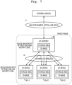
- Fig. 1 illustrates a configuration example of the authentication system according to the first embodiment. Hereinafter, each kind of processing will be described by showing the configuration example of the entire authentication system 100.
- the authentication system 100 includes a firmware generation device 10, a verifier device 20 such as an IoT gateway, a prover device 30 such as an IoT device (simply referred to as "device” as appropriate), and a user operator terminal 40.
- the firmware generation device 10, the verifier device 20, the prover device 30, and the user operator terminal 40 are communicably connected in a wired or wireless manner via a predetermined communication network (not illustrated).
- the authentication system 100 in Fig. 1 may include a plurality of firmware generation devices 10, a plurality of verifier devices 20, a plurality of prover devices 30, or a plurality of user operator terminals 40.
- the firmware generation device 10 is a device (computer) that generates firmware that is a program to be installed in the prover device 30 such as the IoT device.
- the firmware generation device 10 receives an operation from an administrator of the firmware generation device 10, such as a device manufacturer M.
- the firmware generation device 10 is implemented by, for example, a dedicated device for manufacturing IoT devices, a server device, or a desktop PC. In the example of Fig. 1 , the firmware generation device 10 is implemented by a server device.
- the verifier device 20 is a device (computer) that verifies the integrity of the IoT device.
- the verifier device 20 has an integrity verification program (verifier) that verifies whether or not memory information of the IoT device or the like is falsified.
- the verifier device 20 is implemented by an IoT gateway.
- the prover device 30 is a device (computer) that proves the integrity and is a small information device manufactured by the device manufacturer M or the like on the premise of connection to the Internet.
- the prover device 30 has specific information (e.g. media access control (MAC) address and device serial number) for uniquely identifying the IoT device or the like.
- the prover device 30 has an integrity verification program (prover) that proves whether or not the memory information of the IoT device or the like is falsified.
- the prover device 30 is implemented by the IoT device such as a camera.
- the user operator terminal 40 is a device (computer) that updates firmware of the prover device 30 or registers firmware in the verifier device 20.
- the user operator terminal 40 is a terminal used by a user operator (simply referred to as "user" as appropriate) U.
- the user operator terminal 40 is implemented by, for example, a smartphone, a tablet terminal, a laptop personal computer (PC), a desktop PC, a mobile phone, or a personal digital assistant (PDA).
- the user operator terminal 40 is implemented by a desktop PC.
- firmware generation processing (step S1), firmware update/registration processing (steps S2 to S4), formal registration processing (steps S5 to S6), challenge transmission processing (steps S7 to S8), and response transmission processing (steps S9 to S10) will be described as processing of the authentication system 100.
- the following steps S1 to S10 can be performed in different orders. Among the following steps S1 to S10, part of the processing may be omitted.
- the firmware generation device 10 generates firmware (model common firmware) used for challenge-response authentication by writing a random number (hereinafter, "predetermined random number") generated by a predetermined procedure and index information in a free space of the firmware (step S1). Details of the firmware generation processing will be described later in [3. Specific Example of Each Kind of Processing in Authentication System 100] (3-2. Hash Calculation Processing).
- the user operator terminal 40 acquires the firmware of the prover device 30 generated by the firmware generation device 10 (step S2). Then, the user operator terminal 40 updates (firmware update) the prover device 30 such as the IoT device (step S3). Further, the user operator terminal 40 uses the firmware generated by the firmware generation device 10 to register the firmware in the verifier device 20 such as the IoT gateway (step S4). Details of the firmware update/registration processing will be described later in [3. Specific Example of Each Kind of Processing in Authentication System 100] (3-4. Authentication Processing) (3-4-2. Specific Example of Device Registration).
- the prover device 30 issues a formal registration request of the device or the like to the verifier device 20 such as the IoT gateway (step S5). Further, the verifier device 20 formally registers the device or the like (step S6). Details of the formal registration processing will be described later in [3. Specific Example of Each Kind of Processing in Authentication System 100] (3-4. Authentication Processing) (3-4-2. Specific Example of Device Registration).
- the verifier device 20 generates a challenge on the basis of the model common firmware held by the verifier device 20 (step S7). Further, in order to verify the integrity of the IoT device or the like, the verifier device 20 transmits the generated challenge to the prover device 30 (step S8). Details of the formal registration processing will be described later in [3. Specific Example of Each Kind of Processing in Authentication System 100] (3-4. Authentication Processing) (3-4-3. Specific Example of Integrity Verification).
- the prover device 30 generates a response on the basis of the model common firmware included in the prover device 30 (step S9). Further, in order to prove the integrity of the IoT device or the like, the prover device 30 transmits the generated response to the verifier device 20 (step S10). Details of the formal registration processing will be described later in [3. Specific Example of Each Kind of Processing in Authentication System 100] (3-4. Authentication Processing) (3-4-3. Specific Example of Integrity Verification).
- TPIV will be described as a reference technique.
- a technique using TPIV prevents malware from being hidden in a free space of firmware by filling the free space with random number data that is difficult to compress.
- the above technique is used to share information between the IoT gateway (verifier device) and the IoT device (prover device) by using a hash value of the entire firmware in which random numbers are embedded as a common key.
- the firmware can prevent spoofing at the time of initial registration by using the firmware. That is, the firmware can be used as a unique ID for the IoT gateway to verify whether or not a target device is authentic.
- a second advantage is that the above technique can prevent falsification by using the firmware. That is, the firmware can be used as target data of hash calculation for verifying the integrity.
- the technique using TPIV has the following three problems.
- a first problem is that the above technique needs to generate individual firmware incorporating different random numbers for each device, and thus the same firmware cannot be used in the same model.
- a second problem is that, in the above technique, the IoT gateway also needs to manage different types of firmware data for each integrity verification target device, and, when the number of devices increases, an amount of data managed by the IoT gateway increases.
- a third problem is that, in the above technique, a hash value of an entire memory image is taken, and thus a device having a variable portion in a memory is excluded.
- the firmware generation device 10 generates model common firmware used for challenge-response authentication by writing a predetermined random number and index information indicating an area to be subjected to hash calculation in a free space of the firmware, the verifier device 20 that verifies the integrity generates a challenge for the prover device 30 on the basis of the model common firmware held by the verifier device 20, and the prover device 30 that proves the integrity generates a response to the verifier device 20 on the basis of the model common firmware installed in the prover device 30.
- the firmware generation device 10 generates the model common firmware by generating the predetermined random number common to each model of the prover device 30 and the index information including a head address and size of a memory area to be subjected to hash calculation and writing the predetermined random number and the index information in the free space of the firmware.
- the verifier device 20 reads target data of hash calculation by using the index information included in the model common firmware held by the verifier device 20, executes hash calculation by using information specific to the prover device 30 and the target data, and generates the challenge.
- the prover device 30 reads target data of hash calculation by using the index information included in the model common firmware held by the prover device 30, executes hash calculation by using information specific to the prover device 30 and the target data, and generates the response.
- the authentication system 100 contributes to solving the above problems of the technique using TPIV.
- the device manufacturer does not need to create different types of firmware for each device.
- the authentication system 100 uses the common random number for the same model, an amount of data managed by the IoT gateway is reduced by sharing the same firmware data.
- the authentication system 100 causes firmware of a device to include index information indicating a memory range used for hash creation and excludes variable data from a hash target, thereby allowing a device having a variable portion in its memory to be a target of integrity verification.
- the authentication system 100 can verify the integrity as software even for a device that does not have the physical root of trust such as a secure element and add a security function at low cost, that is, can achieve "expansion of target devices".
- a device that does not have the physical root of trust such as a secure element and add a security function at low cost
- the authentication system 100 can use the same software for the same model at a manufacturing stage, that is, can achieve "lowering an introduction barrier". That is, the authentication system 100 verifies the integrity of IoT devices by using model common firmware and thus can effectively verify the integrity of the IoT devices.
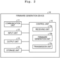
- Fig. 2 is a block diagram illustrating the configuration example of the firmware generation device 10 according to the first embodiment.
- Fig. 3 is a block diagram illustrating the configuration example of the verifier device 20 according to the first embodiment.
- Fig. 4 is a block diagram illustrating the configuration example of the prover device 30 according to the first embodiment.
- the configuration example of the firmware generation device 10 according to the first embodiment will be described in detail with reference to Fig. 2 .
- the firmware generation device 10 includes a communication unit 11, an input unit 12, an output unit 13, a storage unit 14, and a control unit 15. Note that the firmware generation device 10 may not include the input unit 12 or the output unit 13.
- the communication unit 11 is implemented by using, for example, a network interface card (NIC).
- NIC network interface card
- the communication unit 11 is connected to a predetermined communication network in a wired or wireless manner and transmits/receives information to/from various devices.
- the input unit 12 is implemented by, for example, a keyboard or a mouse.
- the input unit 12 receives various operations from the administrator or the like of the firmware generation device 10.
- the output unit 13 is implemented by, for example, a liquid crystal display.
- the output unit 13 displays various types of information.
- the storage unit 14 is implemented by, for example, a semiconductor memory element such as a random access memory (RAM) or a flash memory or a storage device such as a hard disk or an optical disc.
- the storage unit 14 stores various types of information referred to when the control unit 15 operates and stores various types of information acquired when the control unit 15 operates.
- the control unit 15 controls the entire firmware generation device 10.
- the control unit 15 includes a receiving unit 15a, a firmware generation unit 15b, and a transmission unit 15c.
- the control unit 15 is, for example, an electronic circuit such as a central processing unit (CPU) or a micro processing unit (MPU) or an integrated circuit such as an application specific integrated circuit (ASIC) or a field programmable gate array (FPGA).
- CPU central processing unit
- MPU micro processing unit
- ASIC application specific integrated circuit
- FPGA field programmable gate array
- the receiving unit 15a receives various types of information regarding firmware. For example, the receiving unit 15a receives a firmware download request from the user U who is the administrator of the authentication system 100.
- the firmware generation unit 15b generates model common firmware used for challenge-response authentication by writing a predetermined random number and index information indicating an area to be subjected to hash calculation in a free space of the firmware. For example, the firmware generation unit 15b generates the model common firmware by generating the random number common to each model of the prover device and the index information including a head address and size of a memory area to be subjected to hash calculation and writing the random number and the index information in the free space.
- the firmware generation unit 15b stores the generated model common firmware in the storage unit 14.
- the transmission unit 15c transmits various types of information regarding firmware. For example, the transmission unit 15c transmits the generated firmware in response to the firmware download request from the user U who is the administrator of the authentication system 100.
- the verifier device 20 includes a communication unit 21, an input unit 22, an output unit 23, a storage unit 24, and a control unit 25. Note that the verifier device 20 may not include the input unit 22 or the output unit 23.
- the communication unit 21 is implemented by, for example, an NIC.
- the communication unit 21 is connected to a predetermined communication network in a wired or wireless manner and transmits/receives information to/from various devices.
- the input unit 22 is implemented by, for example, a keyboard or a mouse.
- the input unit 22 receives various operations from an administrator or the like of the verifier device 20.
- the output unit 23 is implemented by, for example, a liquid crystal display.
- the output unit 23 displays various types of information.
- the storage unit 24 is implemented by, for example, a semiconductor memory element such as a RAM or a flash memory or a storage device such as a hard disk or an optical disc.
- the storage unit 24 stores various types of information referred to when the control unit 25 operates and stores various types of information acquired when the control unit 25 operates.
- the control unit 25 controls the entire verifier device 20.
- the control unit 25 includes a receiving unit 25a, a challenge generation unit 25b, a transmission unit 25c, and a response verification unit 25d.
- the control unit 25 is, for example, an electronic circuit such as a CPU or an MPU or an integrated circuit such as an ASIC or an FPGA.
- the receiving unit 25a receives various types of information. For example, the receiving unit 25a receives the model common firmware and the information specific to the prover device 30 and stores the received firmware and information in the storage unit 24. The receiving unit 25a also receives a registration request and a response from the prover device 30.
- the challenge generation unit 25b generates a challenge for the prover device 30 on the basis of the model common firmware held by the verifier device 20.
- the challenge generation unit 25b reads target data of hash calculation by using the index information included in the model common firmware held by the verifier device 20, executes hash calculation by using the information specific to the prover device 30 and the target data of hash calculation, and generates a challenge.
- the transmission unit 25c transmits various types of information. For example, the transmission unit 25c transmits the generated challenge to the prover device 30.
- the response verification unit 25d verifies the response received from the prover device 30.
- the response verification unit 25d verifies the response by a method described in [3. Specific Example of Each Kind of Processing in Authentication System 100] (3-1. Integrity Verification Processing) (3-1-6. Integrity Verification Processing of IoT Gateway) described later.
- the prover device 30 includes a communication unit 31, an input unit 32, an output unit 33, a storage unit 34, and a control unit 35. Note that the prover device 30 may not include the input unit 32 or the output unit 33.
- the communication unit 31 is implemented by, for example, an NIC.
- the communication unit 31 is connected to a predetermined communication network in a wired or wireless manner and transmits/receives information to/from various devices.
- the input unit 32 is implemented by, for example, a keyboard or a mouse.
- the input unit 32 receives various operations from an administrator or the like of the prover device 30.
- the output unit 33 is implemented by, for example, a liquid crystal display.
- the output unit 33 displays various types of information.
- the storage unit 34 is implemented by, for example, a semiconductor memory element such as a RAM or a flash memory or a storage device such as a hard disk or an optical disc.
- the storage unit 34 stores various types of information referred to when the control unit 35 operates and stores various types of information acquired when the control unit 35 operates.
- the control unit 35 controls the entire prover device 30.
- the control unit 35 includes a receiving unit 35a, a response generation unit 35b, and a transmission unit 35c.
- the control unit 35 is, for example, an electronic circuit such as a CPU or an MPU or an integrated circuit such as an ASIC or an FPGA.
- the receiving unit 35a receives various types of information. For example, the receiving unit 35a receives the model common firmware. The receiving unit 35a also receives the challenge from the verifier device 20.
- the response generation unit 35b generates a response to the verifier device 20 on the basis of the model common firmware held by the prover device 30. For example, the response generation unit 35b reads target data of hash calculation by using the index information included in the model common firmware installed in the prover device 30, executes hash calculation by using the information specific to the prover device 30 and the target data of hash calculation, and generates a response to the verifier device 20.
- the transmission unit 35c transmits various types of information. For example, the transmission unit 35c transmits a registration request and the generated response to the verifier device 20.
- FIG. 5 illustrates an example of integrity verification according to the first embodiment.
- an IoT gateway cluster head V
- an IoT device node A
- CH V denotes an ID of the cluster head V
- ID A denotes an ID of the node A
- N V denotes a nonce generated by the cluster head V
- P A denotes target data of hash calculation in the node A
- U A denotes information specific to the node A
- K A denotes a hash value of data obtained by combining P A and U A
- PRF denotes a pseudorandom function.
- the IoT gateway extracts P A from firmware data of the node A. At this time, in a case where the IoT gateway fails, the IoT gateway ends as a malicious cluster head (see (1) in Fig. 5 ).
- the IoT gateway sets K Anew as K A .
- the IoT gateway combines P A and U A and calculates K A (see (2) in Fig. 5 ). Then, the IoT gateway generates a disposable random number N V (see (3) in Fig. 5 ). Further, the IoT gateway encrypts N V by using K A (see (4) in Fig. 5 ). Then, the IoT gateway calculates a PRF of ⁇ N V , ID A , CHv ⁇ by using K A as a key (see (5) in Fig. 5 ).
- the IoT gateway transmits, as a challenge, ID A , CH V , the encrypted N V , and the PRF of ⁇ N V , ID A , CHv ⁇ calculated by using K A as keys (see (6) in Fig. 5 ).
- the IoT device sets K Anew as K A .
- the IoT device extracts P A from memory data of the node A, combines P A and U A , and calculates K A (see (7) in Fig. 5 ).
- the IoT device decrypts the encrypted N V included in the challenge by using K A and extracts N V (see (8) in Fig. 5 ).
- the IoT device calculates a PRF of ⁇ N V , ID A , CHv ⁇ by using K A as a key and compares the PRF with a value of the challenge.
- the IoT device determines that a request has been issued from a malicious cluster head (see (9) in Fig. 5 ).
- the IoT device calculates a hash of ⁇ P A , N V , ID A , CH V ⁇ and sets the hash as K Anew (see (10) in Fig. 5 ). Further, the IoT device calculates a PRF of ⁇ ID A , CH V ⁇ by using K Anew as a key (see (11) in Fig. 5 ). Then, the IoT device calculates a PRF of N V by using K A as a key (see (12) in Fig. 5 ).
- the IoT device transmits, as a response, the PRF of N V calculated by using K A as a key and the PRF of ⁇ ID A , CHv ⁇ calculated by using K Anew as a key (see (13) in Fig. 5 ) .
- the IoT gateway calculates a PRF of N V by using K A as a key and compares the PRF with a value of the response (see (14) in Fig. 5 ). Further, the IoT gateway calculates a hash of ⁇ P A , N V , ID A , CHv ⁇ and sets the hash as K Anew (see (15) in Fig. 5 ). Finally, the IoT gateway calculates a PRF of ⁇ ID A , CH V ⁇ by using K Anew as a key and compares the PRF with the value of the response (see (16) in Fig. 5 ). The integrity is successfully verified in a case where both the PRF of N V calculated by using K A as a key and the PRF of ⁇ ID A , CHv ⁇ calculated by using K Anew as a key match with the value of the response.
- FIG. 6 illustrates an example of hash calculation according to the first embodiment.
- a hash calculation method will be described, and then specification of a hash calculation target will be described.
- the firmware generation device 10 fills a free space of firmware with a random number (processing A1). At this time, it is difficult to input different random number values for each device in terms of operation, and thus a common random number is used for the same model. Further, the firmware generation device 10 causes the firmware to include index information indicating a memory range used for hash creation (processing A2).
- the IoT gateway registers in advance firmware of an IoT device to be connected (processing B1).
- the IoT gateway accesses the index information in the firmware and grasps a range of data to be subjected to hash calculation (processing B2).
- a position of the index information itself is described in an integrity verification program (verifier).
- the IoT gateway accesses a file position to be subjected to hash calculation on the basis of the range of the data acquired in the processing B2, thereby acquiring data (processing B3).
- the IoT gateway calculates a hash by adding information specific to the device (e.g. MAC address and device serial number) to the data acquired in the processing B3 (processing B4).
- the IoT device When receiving a challenge from the IoT gateway, the IoT device accesses the index information in the memory and grasps a range of the memory to be subjected to hash calculation (processing C1). At this time, a position of the index information itself is described in an integrity verification program (prover). Next, the IoT device accesses a memory area to be subjected to hash calculation on the basis of the range of the memory acquired in the processing C1, thereby acquiring data (processing C2). Then, the IoT device calculates a hash by adding the information specific to the device (e.g. MAC address and device serial number) to the data acquired in the processing C2 (processing C3) .
- the information specific to the device e.g. MAC address and device serial number
- part of data in a memory image corresponds to a firmware image.
- "app0" in the memory image corresponds to the firmware image.
- random number data and information regarding the area to be subjected to hash calculation are added in a ".flash.text” segment in a firmware image portion "App Image(.bin)" loaded into an "app0" partition.
- part of data in the firmware image corresponds to the area to be subjected to hash calculation.
- ".flash.appdesc.flash.rodata” and ".flash.text" in the firmware image correspond to the area to be subjected to hash calculation.
- the above “.flash.appdesc”, “.flash.rodata”, and “.flash.text” are the area to be subjected to hash calculation.
- the ".flash.text” segment includes a program section and a random number data section, and the random number data section further includes hash calculation area index information.
- the IoT gateway calculates a hash value on the basis of the firmware image, and the IoT device calculates a hash value on the basis of the memory image in the device and compares the hash values.
- the index information includes the number (n) of hash areas and information regarding a "head address” and "size” of each of a "hash area 1", ..., and a "hash area n".
- FIG. 7 illustrates an example of an overview of the communication network according to the first embodiment.
- Fig. 8 illustrates a specific example of the communication network according to the first embodiment.
- the overview of the communication network in the authentication system 100 and the specific example thereof will be described in this order.
- the IoT gateway serving as the verifier device 20 is a device whose root of trust has a high security level.
- IoT devices serving as the prover devices 30 (30-1, 30-2, and 30-3) are devices whose root of trust has a low security level.
- the IoT gateway is connected to an external service via a wide area network (WAN) such as an optical line or fifth generation (5G) (see (1) in Fig. 7 ).
- WAN wide area network
- 5G fifth generation
- the IoT gateway is connected to the IoT devices via a wired or wireless local area network (LAN) (see (2) in Fig. 7 ).
- LAN local area network
- the IoT gateways serving as the verifier devices 20 (20-1, 20-2, and 20-3) can be implemented by using, for example, a 5G gateway.
- IoT devices serving as the prover devices 30 (30-1, 30-2, 30-3, 30-4, and 30-5) can be implemented by using, for example, a security camera and an automated teller machine (ATM).
- ATM automated teller machine
- the IoT gateways can be connected to a 5G core by a virtual private network (VPN) or a dedicated line network via a 5G base station device, for example.
- VPN virtual private network
- 5G base station device for example.
- FIG. 9 illustrates an example of an overview of the authentication processing according to the first embodiment.
- Fig. 10 illustrates a specific example of device registration in the authentication processing according to the first embodiment.
- Fig. 11 illustrates a specific example of integrity verification in the authentication processing according to the first embodiment.
- the overview of the authentication processing in the authentication system 100, the specific example of device registration, and the specific example of integrity verification will be described in this order.
- the device manufacturer M creates firmware including a random number and index information (see (1) in Fig. 9 ).
- the user operator U acquires the firmware of the device by using an existing mechanism provided by the device manufacturer M and updates the firmware of the device (see (2-1) and (2-2) in Fig. 9 ).
- the user operator U arranges the firmware of the device in the IoT gateway in association with device-specific information (see (3) in Fig. 9 ).
- the IoT device transmits a formal registration request to the IoT gateway (see (4) in Fig. 9 ).
- the IoT gateway verifies the integrity of the device by using the device-specific information and firmware registered in advance and formally registers the device when succeeding in the integrity verification.
- the IoT gateway reads hash calculation target data from the firmware image of the IoT device, and the IoT device reads target data of hash calculation from the memory image, generates a hash together with the device-specific information, and verifies the integrity (see (5) in Fig. 9 ).
- a thick arrow indicates transport layer security (TLS) communication
- a medium-thickness arrow indicates message queueing telemetry transport (MQTT) communication
- a broken arrow indicates internal communication
- a thin arrow indicates other kinds of processing.
- TLS transport layer security
- MQTT message queueing telemetry transport
- a broken arrow indicates internal communication
- a thin arrow indicates other kinds of processing.
- the communication system is merely an example, and other systems may be used.
- the user U procures (purchases) an IoT device from the device manufacturer M (see (1) in Fig. 10 ).
- the user U issues a firmware download request to the device manufacturer M (see (2) in Fig. 10 ), and, in response to the request, the device manufacturer M transmits firmware to the user U.
- the user U downloads the firmware (see (3) in Fig. 10 ).
- the user U transmits information specific to the IoT device 30 and the firmware to an IoT gateway (device management) 20B that manages the IoT device and registers the firmware of the device (see (4) in Fig. 10 ).
- the IoT gateway (device management) 20B stores the received information specific to the IoT device 30 and firmware in a device information database.
- the firmware of the IoT device is registered in the IoT gateway through the above processing (2) to (4) in Fig. 10 .
- the user U installs an IoT device (prover) 30 that proves the integrity (see (5) in Fig. 10 ).
- the IoT device 30 transmits the information specific to the IoT device 30 to the IoT gateway (device management) 20B and issues a registration request of the IoT device 30 (see (6) in Fig. 10 ).
- the IoT gateway (device management) 20B transmits the information specific to the IoT device 30 to an IoT gateway (verifier) 20A that verifies the integrity and issues a verification request of the integrity of the IoT device (prover) 30 (see (7) in Fig. 10 ).
- the IoT gateway (verifier) 20A acquires the corresponding firmware from the device information database by using the information specific to the IoT device 30 as a key. Then, the IoT gateway (verifier) 20A verifies the integrity of the IoT device (prover) 30 by challenge-response authentication between the IoT gateway (verifier) 20A and the IoT device (prover) 30 described above in (3-1. Integrity Verification Processing) (see (8) in Fig. 10 ). Further, the IoT gateway (verifier) 20A transmits an integrity verification result to the IoT gateway (device management) 20B (see (9) in Fig. 10 ). Finally, the IoT gateway (device management) 20B stores formal registration of the IoT device (prover) 30 in the device information database. The IoT device whose integrity has been verified is installed through the processing (5) to (9) in Fig. 10 .
- a thick arrow indicates TLS communication
- a medium-thickness arrow indicates MQTT communication
- a broken arrow indicates internal communication
- a thin arrow indicates other kinds of processing.
- the communication system is merely an example, and other systems may be used.
- the user U can set a monitoring execution condition for the IoT gateway (device management) 20B (see (1) in Fig. 11 ).
- the IoT gateway (device management) 20B stores, in the device information database, a received setting of an execution timing in a case where integrity verification is regularly executed.
- a regular monitoring condition of the IoT device (prover) 30 is set through the above processing (1) in Fig. 11 .
- the user U immediately executes integrity verification of the IoT gateway (device management) 20B (see (2) in Fig. 11 ).
- the IoT gateway (device management) 20B issues a notification of execution of the integrity verification to the IoT gateway (verifier) 20A (see (3) in Fig. 11 ).
- the IoT gateway (device management) 20B issues a notification of execution of the integrity verification to the IoT gateway (verifier) 20A on the basis of the monitoring execution condition.
- the IoT gateway (verifier) 20A acquires the corresponding firmware from the device information database by using the information specific to the IoT device 30 (prover) as a key.
- the IoT gateway (verifier) 20A verifies the integrity of the IoT device (prover) 30 by challenge-response authentication between the IoT gateway (verifier) 20A and the IoT device (prover) 30 described above in (3-1. Integrity Verification Processing) (see (4) in Fig. 11 ). Further, the IoT gateway (verifier) 20A transmits an integrity verification result to the IoT gateway (device management) 20B (see (5) in Fig. 11 ). Then, the IoT gateway (device management) 20B stores determination result registration of the IoT device (prover) 30 in the device information database. The integrity verification of the IoT device is executed through the above processing (2) to (5) in Fig. 11 . Finally, the IoT gateway (device management) 20B transmits an integrity verification result to the user U (see (6) in Fig. 11 ).
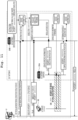
- Fig. 12 is a flowchart showing an example of the flow of the authentication processing according to the first embodiment.
- the following steps S101 to S105 can be performed in different orders. Among the following steps S101 to S105, part of the processing may be omitted.
- the firmware generation device 10 generates model common firmware (step S101). For example, the firmware generation device 10 generates model common firmware used for challenge-response authentication by writing a predetermined random number and index information indicating an area to be subjected to hash calculation in a free space of the firmware.
- the firmware generation device 10 updates and registers the model common firmware (step S102). For example, the firmware generation device 10 updates and registers the model common firmware by transmitting the model common firmware to the verifier device 20 and the prover device 30.
- the verifier device 20 formally registers the prover device 30 (step S103).
- the verifier device 20 formally registers the prover device 30 by challenge-response authentication using the information specific to the prover device 30 and the firmware.
- the verifier device 20 transmits a challenge to the prover device 30 (step S104).
- the verifier device 20 reads target data of hash calculation by using the index information included in the model common firmware held by the verifier device 20, executes hash calculation by using the information specific to the prover device 30 and the target data of hash calculation, generates a challenge for the prover device 30, and transmits the challenge.
- the prover device 30 transmits a response to the verifier device 20 (step S105).
- the prover device 30 reads target data of hash calculation by using the index information included in the model common firmware held by the prover device 30, executes hash calculation by using the information specific to the prover device 30 and the target data of hash calculation, generates a response to the verifier device 20, and transmits the response.
- the firmware generation device 10 generates model common firmware used for challenge-response authentication by writing a predetermined random number and index information indicating an area to be subjected to hash calculation in a free space of the firmware, the verifier device 20 generates a challenge for the prover device 30 on the basis of the model common firmware held by the verifier device 20, and the prover device 30 generates a response to the verifier device 20 on the basis of the model common firmware installed in the prover device 30. This makes it possible to effectively verify the integrity of IoT devices by using the model common firmware.
- the firmware generation device 10 generates the model common firmware by generating the predetermined random number common to each model of the prover device 30 and the index information including a head address and size of a memory area to be subjected to hash calculation and writing the predetermined random number and the index information in the free space. Therefore, because the effective model common firmware is generated, it is possible to more effectively verify the integrity of the IoT devices by using the model common firmware.
- the verifier device 20 reads target data of hash calculation by using the index information included in the model common firmware held by the verifier device 20, executes hash calculation by using the information specific to the prover device 30 and the target data of hash calculation, and generates a challenge for the prover device 30. Therefore, because the effective challenge is generated, it is possible to more effectively verify the integrity of the IoT devices by using the model common firmware.
- the prover device 30 reads target data of hash calculation by using the index information included in the model common firmware installed in the prover device 30, executes hash calculation by using the information specific to the prover device 30 and the target data of hash calculation, and generates a response to the verifier device 20. Therefore, because the effective response is generated, it is possible to more effectively verify the integrity of the IoT devices by using the model common firmware.
- each component of each illustrated device is functionally conceptual and does not necessarily need to be physically configured as illustrated. That is, a specific form of distribution and integration of each device is not limited to the illustrated form, and all or a part thereof can be functionally or physically distributed and integrated in any unit according to various loads, usage conditions, and the like. Further, all or some of the processing functions performed in each device can be implemented by a CPU and a program analyzed and executed by the CPU or can be implemented as hardware by wired logic.
- Fig. 13 illustrates a computer that executes the program.
- a computer 1000 includes, for example, a memory 1010, a CPU 1020, a hard disk drive interface 1030, a disk drive interface 1040, a serial port interface 1050, a video adapter 1060, and a network interface 1070. Those units are connected by a bus 1080.
- the memory 1010 includes a read only memory (ROM) 1011 and a RAM 1012.
- the ROM 1011 stores, for example, a boot program such as a basic input output system (BIOS).
- BIOS basic input output system
- the hard disk drive interface 1030 is connected to a hard disk drive 1090 as illustrated in Fig. 13 .
- the disk drive interface 1040 is connected to a disk drive 1100 as illustrated in Fig. 13 .
- a removable storage medium such as a magnetic disk or an optical disc is inserted into the disk drive 1100.
- the serial port interface 1050 is connected to, for example, a mouse 1110 and a keyboard 1120 as illustrated in Fig. 13 .
- the video adapter 1060 is connected to, for example, a display 1130 as illustrated in Fig. 13 .
- the hard disk drive 1090 stores, for example, an OS 1091, an application program 1092, a program module 1093, and program data 1094 as illustrated in Fig. 13 . That is, the above program is stored in, for example, the hard disk drive 1090 as a program module in which commands executed by the computer 1000 are written.
- Various types of data described in the above embodiments are stored as program data in, for example, the memory 1010 and the hard disk drive 1090.
- the CPU 1020 reads the program module 1093 and the program data 1094 stored in the memory 1010 and the hard disk drive 1090 to the RAM 1012 as necessary and executes various processing procedures.
- program module 1093 and the program data 1094 regarding the program are not limited to being stored in the hard disk drive 1090 and may be stored in, for example, a removable storage medium and read by the CPU 1020 via the disk drive or the like.
- the program module 1093 and the program data 1094 regarding the program may be stored in another computer connected via a network (e.g. local area network (LAN) or wide area network (WAN)) and be read by the CPU 1020 via the network interface 1070.
- LAN local area network
- WAN wide area network
Landscapes
- Engineering & Computer Science (AREA)
- Computer Security & Cryptography (AREA)
- Theoretical Computer Science (AREA)
- Computer Hardware Design (AREA)
- General Engineering & Computer Science (AREA)
- Software Systems (AREA)
- General Physics & Mathematics (AREA)
- Physics & Mathematics (AREA)
- Computer Networks & Wireless Communication (AREA)
- Signal Processing (AREA)
- Stored Programmes (AREA)
- Storage Device Security (AREA)
- Detection And Correction Of Errors (AREA)
Abstract
Description
- The present invention relates to an authentication system, a generation device, a generation method, and a generation program.
- Malware (e.g. Mirai) invades not only information and communication technology (ICT) devices such as personal computers (PCs) but also Internet of Things (IoT) devices and the like that do not have hardware such as a secure element and causes the devices to participate in a botnet, which causes widespread damage to the devices.
- Non Patent Literature 1: Sarita Agrawal, Manik Lal Das, Javier Lopez, "Detection of Node Capture Attack in Wireless Sensor Networks", IEEE SYSTEMS JOURNAL, VOL. 13, MARCH 2019 <https://ieeexplore.ieee.org/document/8444374>
- However, the related art cannot effectively verify integrity of IoT devices. This is because, although a physical root of trust such as a security chip is generally used to ensure security of ICT devices, the physical root of trust is frequently not mounted in a dedicated device such as an IoT device or a communication device.
- In a case where the physical root of trust is not mounted, the related art needs to generate individual firmware incorporating different random numbers for each device. Therefore, the same firmware cannot be used in the same model. Further, in the above related art, an IoT gateway also needs to manage different types of firmware data for each integrity verification target device, and, when the number of devices increases, an amount of data managed by the IoT gateway increases. Furthermore, in the above related art, a hash value of an entire memory image is taken, and thus a device having a variable portion in a memory is excluded.
- The present invention has been made in view of the above, and an object thereof is to provide an authentication system, a generation device, a generation method, and a generation program capable of effectively verifying integrity of IoT devices.
- In order to solve the above problem and achieve the object, an authentication system according to the present invention is an authentication system including a generation device that generates firmware, a verifier device that verifies integrity, and a prover device that proves the integrity, in which: the generation device includes a firmware generation unit that generates model common firmware used for challenge-response authentication by writing a predetermined random number and index information indicating an area to be subjected to hash calculation in a free space of the firmware; the verifier device includes a challenge generation unit that generates a challenge for the prover device on the basis of the model common firmware held by the verifier device; and the prover device includes a response generation unit that generates a response to the verifier device on the basis of the model common firmware held by the prover device.
- In order to solve the above problem and achieve the object, a generation device according to the present invention includes a firmware generation unit that generates model common firmware used for challenge-response authentication by writing a predetermined random number and index information indicating an area to be subjected to hash calculation in a free space of the firmware.
- A generation method according to the present invention is a generation method performed by a generation device, the generation method including a firmware generation step of generating model common firmware used for challenge-response authentication by writing a predetermined random number and index information indicating an area to be subjected to hash calculation in a free space of the firmware.
- A generation program according to the present invention causes a computer to execute a firmware generation procedure of generating model common firmware used for challenge-response authentication by writing a predetermined random number and index information indicating an area to be subjected to hash calculation in a free space of the firmware.
- The present invention can effectively verify integrity of IoT devices by using model common firmware.
-
-
Fig. 1 illustrates a configuration example of an authentication system according to a first embodiment. -
Fig. 2 is a block diagram illustrating a configuration example of a firmware generation device according to the first embodiment. -
Fig. 3 is a block diagram illustrating a configuration example of a verifier device according to the first embodiment. -
Fig. 4 is a block diagram illustrating a configuration example of a prover device according to the first embodiment. -
Fig. 5 illustrates an example of integrity verification according to the first embodiment. -
Fig. 6 illustrates an example of hash calculation according to the first embodiment. -
Fig. 7 illustrates an example of an overview of a communication network according to the first embodiment. -
Fig. 8 illustrates a specific example of the communication network according to the first embodiment. -
Fig. 9 illustrates an example of an overview of authentication processing according to the first embodiment. -
Fig. 10 illustrates a specific example of device registration in the authentication processing according to the first embodiment. -
Fig. 11 illustrates a specific example of integrity verification in the authentication processing according to the first embodiment. -
Fig. 12 is a flowchart showing an example of a flow of the authentication processing according to the first embodiment. -
Fig. 13 illustrates a computer that executes a program. - Hereinafter, embodiments of a firmware generation device (generation device), a firmware generation method (generation method), and a firmware generation program (generation program) according to the present invention will be described in detail with reference to the drawings. Note that the present invention is not limited to the embodiments described below.
- Hereinafter, a configuration of an
authentication system 100 according to a first embodiment, a configuration of each device of theauthentication system 100, a specific example of each kind of processing, and a flow of authentication processing will be described in this order, and, finally, effects of the first embodiment will be described. - The configuration of the
authentication system 100 according to the first embodiment will be described in detail with reference toFig. 1. Fig. 1 illustrates a configuration example of the authentication system according to the first embodiment. Hereinafter, each kind of processing will be described by showing the configuration example of theentire authentication system 100. - As illustrated in
Fig. 1 , theauthentication system 100 includes afirmware generation device 10, averifier device 20 such as an IoT gateway, aprover device 30 such as an IoT device (simply referred to as "device" as appropriate), and auser operator terminal 40. Thefirmware generation device 10, theverifier device 20, theprover device 30, and theuser operator terminal 40 are communicably connected in a wired or wireless manner via a predetermined communication network (not illustrated). Theauthentication system 100 inFig. 1 may include a plurality offirmware generation devices 10, a plurality ofverifier devices 20, a plurality ofprover devices 30, or a plurality ofuser operator terminals 40. - The
firmware generation device 10 is a device (computer) that generates firmware that is a program to be installed in theprover device 30 such as the IoT device. Thefirmware generation device 10 receives an operation from an administrator of thefirmware generation device 10, such as a device manufacturer M. Thefirmware generation device 10 is implemented by, for example, a dedicated device for manufacturing IoT devices, a server device, or a desktop PC. In the example ofFig. 1 , thefirmware generation device 10 is implemented by a server device. - The
verifier device 20 is a device (computer) that verifies the integrity of the IoT device. Theverifier device 20 has an integrity verification program (verifier) that verifies whether or not memory information of the IoT device or the like is falsified. In the example ofFig. 1 , theverifier device 20 is implemented by an IoT gateway. - The
prover device 30 is a device (computer) that proves the integrity and is a small information device manufactured by the device manufacturer M or the like on the premise of connection to the Internet. Theprover device 30 has specific information (e.g. media access control (MAC) address and device serial number) for uniquely identifying the IoT device or the like. Theprover device 30 has an integrity verification program (prover) that proves whether or not the memory information of the IoT device or the like is falsified. In the example ofFig. 1 , theprover device 30 is implemented by the IoT device such as a camera. - The
user operator terminal 40 is a device (computer) that updates firmware of theprover device 30 or registers firmware in theverifier device 20. Theuser operator terminal 40 is a terminal used by a user operator (simply referred to as "user" as appropriate) U. - The
user operator terminal 40 is implemented by, for example, a smartphone, a tablet terminal, a laptop personal computer (PC), a desktop PC, a mobile phone, or a personal digital assistant (PDA). In the example ofFig. 1 , theuser operator terminal 40 is implemented by a desktop PC. - Hereinafter, firmware generation processing (step S1), firmware update/registration processing (steps S2 to S4), formal registration processing (steps S5 to S6), challenge transmission processing (steps S7 to S8), and response transmission processing (steps S9 to S10) will be described as processing of the
authentication system 100. The following steps S1 to S10 can be performed in different orders. Among the following steps S1 to S10, part of the processing may be omitted. - First, the
firmware generation device 10 generates firmware (model common firmware) used for challenge-response authentication by writing a random number (hereinafter, "predetermined random number") generated by a predetermined procedure and index information in a free space of the firmware (step S1). Details of the firmware generation processing will be described later in [3. Specific Example of Each Kind of Processing in Authentication System 100] (3-2. Hash Calculation Processing). - Next, the
user operator terminal 40 acquires the firmware of theprover device 30 generated by the firmware generation device 10 (step S2). Then, theuser operator terminal 40 updates (firmware update) theprover device 30 such as the IoT device (step S3). Further, theuser operator terminal 40 uses the firmware generated by thefirmware generation device 10 to register the firmware in theverifier device 20 such as the IoT gateway (step S4). Details of the firmware update/registration processing will be described later in [3. Specific Example of Each Kind of Processing in Authentication System 100] (3-4. Authentication Processing) (3-4-2. Specific Example of Device Registration). - Then, the
prover device 30 issues a formal registration request of the device or the like to theverifier device 20 such as the IoT gateway (step S5). Further, theverifier device 20 formally registers the device or the like (step S6). Details of the formal registration processing will be described later in [3. Specific Example of Each Kind of Processing in Authentication System 100] (3-4. Authentication Processing) (3-4-2. Specific Example of Device Registration). - Then, the
verifier device 20 generates a challenge on the basis of the model common firmware held by the verifier device 20 (step S7). Further, in order to verify the integrity of the IoT device or the like, theverifier device 20 transmits the generated challenge to the prover device 30 (step S8). Details of the formal registration processing will be described later in [3. Specific Example of Each Kind of Processing in Authentication System 100] (3-4. Authentication Processing) (3-4-3. Specific Example of Integrity Verification). - Then, the
prover device 30 generates a response on the basis of the model common firmware included in the prover device 30 (step S9). Further, in order to prove the integrity of the IoT device or the like, theprover device 30 transmits the generated response to the verifier device 20 (step S10). Details of the formal registration processing will be described later in [3. Specific Example of Each Kind of Processing in Authentication System 100] (3-4. Authentication Processing) (3-4-3. Specific Example of Integrity Verification). - Hereinafter, effects of the
authentication system 100 will be described in detail by describing problems of Trusted platform module enabled Program Integrity Verification (TPIV) as a reference technique. - First, TPIV will be described as a reference technique. A technique using TPIV prevents malware from being hidden in a free space of firmware by filling the free space with random number data that is difficult to compress. The above technique is used to share information between the IoT gateway (verifier device) and the IoT device (prover device) by using a hash value of the entire firmware in which random numbers are embedded as a common key. At this time, the following two advantages are expected by using the firmware. A first advantage is that the above technique can prevent spoofing at the time of initial registration by using the firmware. That is, the firmware can be used as a unique ID for the IoT gateway to verify whether or not a target device is authentic. A second advantage is that the above technique can prevent falsification by using the firmware. That is, the firmware can be used as target data of hash calculation for verifying the integrity.
- However, the technique using TPIV has the following three problems. A first problem is that the above technique needs to generate individual firmware incorporating different random numbers for each device, and thus the same firmware cannot be used in the same model. A second problem is that, in the above technique, the IoT gateway also needs to manage different types of firmware data for each integrity verification target device, and, when the number of devices increases, an amount of data managed by the IoT gateway increases. A third problem is that, in the above technique, a hash value of an entire memory image is taken, and thus a device having a variable portion in a memory is excluded.
- In the
authentication system 100, thefirmware generation device 10 generates model common firmware used for challenge-response authentication by writing a predetermined random number and index information indicating an area to be subjected to hash calculation in a free space of the firmware, theverifier device 20 that verifies the integrity generates a challenge for theprover device 30 on the basis of the model common firmware held by theverifier device 20, and theprover device 30 that proves the integrity generates a response to theverifier device 20 on the basis of the model common firmware installed in theprover device 30. - Further, in the
authentication system 100, thefirmware generation device 10 generates the model common firmware by generating the predetermined random number common to each model of theprover device 30 and the index information including a head address and size of a memory area to be subjected to hash calculation and writing the predetermined random number and the index information in the free space of the firmware. Theverifier device 20 reads target data of hash calculation by using the index information included in the model common firmware held by theverifier device 20, executes hash calculation by using information specific to theprover device 30 and the target data, and generates the challenge. Theprover device 30 reads target data of hash calculation by using the index information included in the model common firmware held by theprover device 30, executes hash calculation by using information specific to theprover device 30 and the target data, and generates the response. - Therefore, the
authentication system 100 contributes to solving the above problems of the technique using TPIV. For the first problem, because theauthentication system 100 uses a common random number for the same model, the device manufacturer does not need to create different types of firmware for each device. For the second problem, because theauthentication system 100 uses the common random number for the same model, an amount of data managed by the IoT gateway is reduced by sharing the same firmware data. For the third problem, theauthentication system 100 causes firmware of a device to include index information indicating a memory range used for hash creation and excludes variable data from a hash target, thereby allowing a device having a variable portion in its memory to be a target of integrity verification. - From the above, the
authentication system 100 can verify the integrity as software even for a device that does not have the physical root of trust such as a secure element and add a security function at low cost, that is, can achieve "expansion of target devices". In addition, in an actual device manufacturing site, it is difficult to incorporate different kinds of software for each individual device to distribute and manage the devices in terms of cost and operation. Theauthentication system 100 can use the same software for the same model at a manufacturing stage, that is, can achieve "lowering an introduction barrier". That is, theauthentication system 100 verifies the integrity of IoT devices by using model common firmware and thus can effectively verify the integrity of the IoT devices. - Configuration examples of the
firmware generation device 10, theverifier device 20, and theprover device 30 according to the first embodiment will be described in detail with reference toFigs. 2 to 4 .Fig. 2 is a block diagram illustrating the configuration example of thefirmware generation device 10 according to the first embodiment.Fig. 3 is a block diagram illustrating the configuration example of theverifier device 20 according to the first embodiment.Fig. 4 is a block diagram illustrating the configuration example of theprover device 30 according to the first embodiment. - The configuration example of the
firmware generation device 10 according to the first embodiment will be described in detail with reference toFig. 2 . Thefirmware generation device 10 includes acommunication unit 11, an input unit 12, anoutput unit 13, astorage unit 14, and a control unit 15. Note that thefirmware generation device 10 may not include the input unit 12 or theoutput unit 13. - The
communication unit 11 is implemented by using, for example, a network interface card (NIC). Thecommunication unit 11 is connected to a predetermined communication network in a wired or wireless manner and transmits/receives information to/from various devices. - The input unit 12 is implemented by, for example, a keyboard or a mouse. The input unit 12 receives various operations from the administrator or the like of the
firmware generation device 10. - The
output unit 13 is implemented by, for example, a liquid crystal display. Theoutput unit 13 displays various types of information. - The
storage unit 14 is implemented by, for example, a semiconductor memory element such as a random access memory (RAM) or a flash memory or a storage device such as a hard disk or an optical disc. Thestorage unit 14 stores various types of information referred to when the control unit 15 operates and stores various types of information acquired when the control unit 15 operates. - The control unit 15 controls the entire
firmware generation device 10. The control unit 15 includes a receiving unit 15a, afirmware generation unit 15b, and atransmission unit 15c. The control unit 15 is, for example, an electronic circuit such as a central processing unit (CPU) or a micro processing unit (MPU) or an integrated circuit such as an application specific integrated circuit (ASIC) or a field programmable gate array (FPGA). - The receiving unit 15a receives various types of information regarding firmware. For example, the receiving unit 15a receives a firmware download request from the user U who is the administrator of the
authentication system 100. - The
firmware generation unit 15b generates model common firmware used for challenge-response authentication by writing a predetermined random number and index information indicating an area to be subjected to hash calculation in a free space of the firmware. For example, thefirmware generation unit 15b generates the model common firmware by generating the random number common to each model of the prover device and the index information including a head address and size of a memory area to be subjected to hash calculation and writing the random number and the index information in the free space. - Meanwhile, the
firmware generation unit 15b stores the generated model common firmware in thestorage unit 14. - The
transmission unit 15c transmits various types of information regarding firmware. For example, thetransmission unit 15c transmits the generated firmware in response to the firmware download request from the user U who is the administrator of theauthentication system 100. - A configuration example of the
verifier device 20 according to the first embodiment will be described in detail with reference toFig. 3 . Theverifier device 20 includes a communication unit 21, an input unit 22, anoutput unit 23, a storage unit 24, and acontrol unit 25. Note that theverifier device 20 may not include the input unit 22 or theoutput unit 23. - The communication unit 21 is implemented by, for example, an NIC. The communication unit 21 is connected to a predetermined communication network in a wired or wireless manner and transmits/receives information to/from various devices.
- The input unit 22 is implemented by, for example, a keyboard or a mouse. The input unit 22 receives various operations from an administrator or the like of the
verifier device 20. - The
output unit 23 is implemented by, for example, a liquid crystal display. Theoutput unit 23 displays various types of information. - The storage unit 24 is implemented by, for example, a semiconductor memory element such as a RAM or a flash memory or a storage device such as a hard disk or an optical disc. The storage unit 24 stores various types of information referred to when the
control unit 25 operates and stores various types of information acquired when thecontrol unit 25 operates. - The
control unit 25 controls theentire verifier device 20. Thecontrol unit 25 includes a receivingunit 25a, achallenge generation unit 25b, a transmission unit 25c, and aresponse verification unit 25d. Thecontrol unit 25 is, for example, an electronic circuit such as a CPU or an MPU or an integrated circuit such as an ASIC or an FPGA. - The receiving
unit 25a receives various types of information. For example, the receivingunit 25a receives the model common firmware and the information specific to theprover device 30 and stores the received firmware and information in the storage unit 24. The receivingunit 25a also receives a registration request and a response from theprover device 30. - The
challenge generation unit 25b generates a challenge for theprover device 30 on the basis of the model common firmware held by theverifier device 20. For example, thechallenge generation unit 25b reads target data of hash calculation by using the index information included in the model common firmware held by theverifier device 20, executes hash calculation by using the information specific to theprover device 30 and the target data of hash calculation, and generates a challenge. - The transmission unit 25c transmits various types of information. For example, the transmission unit 25c transmits the generated challenge to the
prover device 30. - The
response verification unit 25d verifies the response received from theprover device 30. For example, theresponse verification unit 25d verifies the response by a method described in [3. Specific Example of Each Kind of Processing in Authentication System 100] (3-1. Integrity Verification Processing) (3-1-6. Integrity Verification Processing of IoT Gateway) described later. - A configuration example of the
prover device 30 according to the first embodiment will be described in detail with reference toFig. 4 . Theprover device 30 includes a communication unit 31, an input unit 32, an output unit 33, a storage unit 34, and acontrol unit 35. Note that theprover device 30 may not include the input unit 32 or the output unit 33. - The communication unit 31 is implemented by, for example, an NIC. The communication unit 31 is connected to a predetermined communication network in a wired or wireless manner and transmits/receives information to/from various devices.
- The input unit 32 is implemented by, for example, a keyboard or a mouse. The input unit 32 receives various operations from an administrator or the like of the
prover device 30. - The output unit 33 is implemented by, for example, a liquid crystal display. The output unit 33 displays various types of information.
- The storage unit 34 is implemented by, for example, a semiconductor memory element such as a RAM or a flash memory or a storage device such as a hard disk or an optical disc. The storage unit 34 stores various types of information referred to when the
control unit 35 operates and stores various types of information acquired when thecontrol unit 35 operates. - The
control unit 35 controls theentire prover device 30. Thecontrol unit 35 includes a receivingunit 35a, aresponse generation unit 35b, and atransmission unit 35c. Thecontrol unit 35 is, for example, an electronic circuit such as a CPU or an MPU or an integrated circuit such as an ASIC or an FPGA. - The receiving
unit 35a receives various types of information. For example, the receivingunit 35a receives the model common firmware. The receivingunit 35a also receives the challenge from theverifier device 20. - The
response generation unit 35b generates a response to theverifier device 20 on the basis of the model common firmware held by theprover device 30. For example, theresponse generation unit 35b reads target data of hash calculation by using the index information included in the model common firmware installed in theprover device 30, executes hash calculation by using the information specific to theprover device 30 and the target data of hash calculation, and generates a response to theverifier device 20. - The
transmission unit 35c transmits various types of information. For example, thetransmission unit 35c transmits a registration request and the generated response to theverifier device 20. - A specific example of each kind of processing in the
authentication system 100 according to the first embodiment will be described with reference toFigs. 5 to 11 . Hereinafter, integrity verification processing, hash calculation processing, a communication network, and authentication processing will be described in this order. - A specific example of the integrity verification processing in the
authentication system 100 will be described with reference toFig. 5. Fig. 5 illustrates an example of integrity verification according to the first embodiment. Hereinafter, a specific example where an IoT gateway (cluster head V) is employed as theverifier device 20 and an IoT device (node A) is employed as theprover device 30 will be described. Further, hereinafter, CHV denotes an ID of the cluster head V, IDA denotes an ID of the node A, NV denotes a nonce generated by the cluster head V, PA denotes target data of hash calculation in the node A, UA denotes information specific to the node A, KA denotes a hash value of data obtained by combining PA and UA, and PRF denotes a pseudorandom function. - First, in a case where KAnew is not set, the IoT gateway extracts PA from firmware data of the node A. At this time, in a case where the IoT gateway fails, the IoT gateway ends as a malicious cluster head (see (1) in
Fig. 5 ). Next, in a case where KAnew is set, the IoT gateway sets KAnew as KA. At this time, in a case where KAnew is not set, the IoT gateway combines PA and UA and calculates KA (see (2) inFig. 5 ). Then, the IoT gateway generates a disposable random number NV (see (3) inFig. 5 ). Further, the IoT gateway encrypts NV by using KA (see (4) inFig. 5 ). Then, the IoT gateway calculates a PRF of {NV, IDA, CHv} by using KA as a key (see (5) inFig. 5 ). - The IoT gateway transmits, as a challenge, IDA, CHV, the encrypted NV, and the PRF of {NV, IDA, CHv} calculated by using KA as keys (see (6) in
Fig. 5 ). - First, in a case where KAnew is set, the IoT device sets KAnew as KA. At this time, in a case where KAnew is not set, the IoT device extracts PA from memory data of the node A, combines PA and UA, and calculates KA (see (7) in
Fig. 5 ). Next, the IoT device decrypts the encrypted NV included in the challenge by using KA and extracts NV (see (8) inFig. 5 ). Then, the IoT device calculates a PRF of {NV, IDA, CHv} by using KA as a key and compares the PRF with a value of the challenge. At this time, in a case where the PRF and the value of the challenge do not match, the IoT device determines that a request has been issued from a malicious cluster head (see (9) inFig. 5 ). - Then, the IoT device calculates a hash of {PA, NV, IDA, CHV} and sets the hash as KAnew (see (10) in
Fig. 5 ). Further, the IoT device calculates a PRF of {IDA, CHV} by using KAnew as a key (see (11) inFig. 5 ). Then, the IoT device calculates a PRF of NV by using KA as a key (see (12) inFig. 5 ). - The IoT device transmits, as a response, the PRF of NV calculated by using KA as a key and the PRF of {IDA, CHv} calculated by using KAnew as a key (see (13) in
Fig. 5 ) . - The IoT gateway calculates a PRF of NV by using KA as a key and compares the PRF with a value of the response (see (14) in
Fig. 5 ). Further, the IoT gateway calculates a hash of {PA, NV, IDA, CHv} and sets the hash as KAnew (see (15) inFig. 5 ). Finally, the IoT gateway calculates a PRF of {IDA, CHV} by using KAnew as a key and compares the PRF with the value of the response (see (16) inFig. 5 ). The integrity is successfully verified in a case where both the PRF of NV calculated by using KA as a key and the PRF of {IDA, CHv} calculated by using KAnew as a key match with the value of the response. - A specific example of the hash calculation processing in the
authentication system 100 will be described with reference toFig. 6. Fig. 6 illustrates an example of hash calculation according to the first embodiment. Hereinafter, a hash calculation method will be described, and then specification of a hash calculation target will be described. - Hereinafter, hash calculation methods of the
firmware generation device 10, the IoT gateway serving as theverifier device 20, and the IoT device serving as theprover device 30 according to the first embodiment will be described in this order. - The
firmware generation device 10 fills a free space of firmware with a random number (processing A1). At this time, it is difficult to input different random number values for each device in terms of operation, and thus a common random number is used for the same model. Further, thefirmware generation device 10 causes the firmware to include index information indicating a memory range used for hash creation (processing A2). - The IoT gateway registers in advance firmware of an IoT device to be connected (processing B1). Next, when receiving a registration request from the IoT device, the IoT gateway accesses the index information in the firmware and grasps a range of data to be subjected to hash calculation (processing B2). At this time, a position of the index information itself is described in an integrity verification program (verifier). Then, the IoT gateway accesses a file position to be subjected to hash calculation on the basis of the range of the data acquired in the processing B2, thereby acquiring data (processing B3). Then, the IoT gateway calculates a hash by adding information specific to the device (e.g. MAC address and device serial number) to the data acquired in the processing B3 (processing B4).
- When receiving a challenge from the IoT gateway, the IoT device accesses the index information in the memory and grasps a range of the memory to be subjected to hash calculation (processing C1). At this time, a position of the index information itself is described in an integrity verification program (prover). Next, the IoT device accesses a memory area to be subjected to hash calculation on the basis of the range of the memory acquired in the processing C1, thereby acquiring data (processing C2). Then, the IoT device calculates a hash by adding the information specific to the device (e.g. MAC address and device serial number) to the data acquired in the processing C2 (processing C3) .
- Hereinafter, specification of the hash calculation target according to the first embodiment in a case where a DFRobot DRF0478 is used as an example of the IoT device will be described in the following order: a memory image, a firmware image, the area to be subjected to hash calculation, and the index information.
- As illustrated in (1) in
Fig. 6 , part of data in a memory image corresponds to a firmware image. In the example of (1) inFig. 6 , "app0" in the memory image corresponds to the firmware image. At this time, random number data and information regarding the area to be subjected to hash calculation are added in a ".flash.text" segment in a firmware image portion "App Image(.bin)" loaded into an "app0" partition. - As illustrated in (2) in
Fig. 6 , part of data in the firmware image corresponds to the area to be subjected to hash calculation. In the example of (2) inFig. 6 , ".flash.appdesc.flash.rodata" and ".flash.text" in the firmware image correspond to the area to be subjected to hash calculation. - As illustrated in (3) in
Fig. 6 , the above ".flash.appdesc", ".flash.rodata", and ".flash.text" are the area to be subjected to hash calculation. The ".flash.text" segment includes a program section and a random number data section, and the random number data section further includes hash calculation area index information. At this time, the IoT gateway calculates a hash value on the basis of the firmware image, and the IoT device calculates a hash value on the basis of the memory image in the device and compares the hash values. - As illustrated in (4) in
Fig. 6 , the index information includes the number (n) of hash areas and information regarding a "head address" and "size" of each of a "hash area 1", ..., and a "hash area n". - A specific example of the communication network in the
authentication system 100 will be described with reference toFigs. 7 to 8 .Fig. 7 illustrates an example of an overview of the communication network according to the first embodiment.Fig. 8 illustrates a specific example of the communication network according to the first embodiment. Hereinafter, the overview of the communication network in theauthentication system 100 and the specific example thereof will be described in this order. - The overview of the communication network in the
authentication system 100 will be described with reference toFig. 7 . As illustrated inFig. 7 , the IoT gateway serving as theverifier device 20 is a device whose root of trust has a high security level. IoT devices serving as the prover devices 30 (30-1, 30-2, and 30-3) are devices whose root of trust has a low security level. The IoT gateway is connected to an external service via a wide area network (WAN) such as an optical line or fifth generation (5G) (see (1) inFig. 7 ). Further, the IoT gateway is connected to the IoT devices via a wired or wireless local area network (LAN) (see (2) inFig. 7 ). - A specific example of the communication network in the
authentication system 100 will be described with reference toFig. 8 . As illustrated inFig. 8 , the IoT gateways serving as the verifier devices 20 (20-1, 20-2, and 20-3) can be implemented by using, for example, a 5G gateway. IoT devices serving as the prover devices 30 (30-1, 30-2, 30-3, 30-4, and 30-5) can be implemented by using, for example, a security camera and an automated teller machine (ATM). The IoT gateways can be connected to a 5G core by a virtual private network (VPN) or a dedicated line network via a 5G base station device, for example. - A specific example of the authentication processing in the
authentication system 100 will be described with reference toFigs. 9 to 11 .Fig. 9 illustrates an example of an overview of the authentication processing according to the first embodiment.Fig. 10 illustrates a specific example of device registration in the authentication processing according to the first embodiment.Fig. 11 illustrates a specific example of integrity verification in the authentication processing according to the first embodiment. Hereinafter, the overview of the authentication processing in theauthentication system 100, the specific example of device registration, and the specific example of integrity verification will be described in this order. - The overview of the authentication processing in the
authentication system 100 will be described with reference toFig. 9 . As illustrated inFig. 9 , first, the device manufacturer M creates firmware including a random number and index information (see (1) inFig. 9 ). Next, the user operator U acquires the firmware of the device by using an existing mechanism provided by the device manufacturer M and updates the firmware of the device (see (2-1) and (2-2) inFig. 9 ). Then, the user operator U arranges the firmware of the device in the IoT gateway in association with device-specific information (see (3) inFig. 9 ). Then, the IoT device transmits a formal registration request to the IoT gateway (see (4) inFig. 9 ). At this time, the IoT gateway verifies the integrity of the device by using the device-specific information and firmware registered in advance and formally registers the device when succeeding in the integrity verification. In the integrity verification, the IoT gateway reads hash calculation target data from the firmware image of the IoT device, and the IoT device reads target data of hash calculation from the memory image, generates a hash together with the device-specific information, and verifies the integrity (see (5) inFig. 9 ). - A specific example of device registration in the
authentication system 100 will be described with reference toFig. 10 . Here, among arrows inFig. 10 , a thick arrow indicates transport layer security (TLS) communication, a medium-thickness arrow indicates message queueing telemetry transport (MQTT) communication, a broken arrow indicates internal communication, and a thin arrow indicates other kinds of processing. Note that the communication system is merely an example, and other systems may be used. - First, the user U procures (purchases) an IoT device from the device manufacturer M (see (1) in
Fig. 10 ). Next, the user U issues a firmware download request to the device manufacturer M (see (2) inFig. 10 ), and, in response to the request, the device manufacturer M transmits firmware to the user U. Thus, the user U downloads the firmware (see (3) inFig. 10 ). Further, the user U transmits information specific to theIoT device 30 and the firmware to an IoT gateway (device management) 20B that manages the IoT device and registers the firmware of the device (see (4) inFig. 10 ). At this time, the IoT gateway (device management) 20B stores the received information specific to theIoT device 30 and firmware in a device information database. The firmware of the IoT device is registered in the IoT gateway through the above processing (2) to (4) inFig. 10 . - The user U installs an IoT device (prover) 30 that proves the integrity (see (5) in
Fig. 10 ). Next, theIoT device 30 transmits the information specific to theIoT device 30 to the IoT gateway (device management) 20B and issues a registration request of the IoT device 30 (see (6) inFig. 10 ). Then, the IoT gateway (device management) 20B transmits the information specific to theIoT device 30 to an IoT gateway (verifier) 20A that verifies the integrity and issues a verification request of the integrity of the IoT device (prover) 30 (see (7) inFig. 10 ). The IoT gateway (verifier) 20A acquires the corresponding firmware from the device information database by using the information specific to theIoT device 30 as a key. Then, the IoT gateway (verifier) 20A verifies the integrity of the IoT device (prover) 30 by challenge-response authentication between the IoT gateway (verifier) 20A and the IoT device (prover) 30 described above in (3-1. Integrity Verification Processing) (see (8) inFig. 10 ). Further, the IoT gateway (verifier) 20A transmits an integrity verification result to the IoT gateway (device management) 20B (see (9) inFig. 10 ). Finally, the IoT gateway (device management) 20B stores formal registration of the IoT device (prover) 30 in the device information database. The IoT device whose integrity has been verified is installed through the processing (5) to (9) inFig. 10 . - A specific example of the integrity verification in the
authentication system 100 will be described with reference toFig. 11 . Here, among arrows inFig. 11 , a thick arrow indicates TLS communication, a medium-thickness arrow indicates MQTT communication, a broken arrow indicates internal communication, and a thin arrow indicates other kinds of processing. Note that the communication system is merely an example, and other systems may be used. - First, the user U can set a monitoring execution condition for the IoT gateway (device management) 20B (see (1) in
Fig. 11 ). At this time, the IoT gateway (device management) 20B stores, in the device information database, a received setting of an execution timing in a case where integrity verification is regularly executed. A regular monitoring condition of the IoT device (prover) 30 is set through the above processing (1) inFig. 11 . - The user U immediately executes integrity verification of the IoT gateway (device management) 20B (see (2) in
Fig. 11 ). At this time, the IoT gateway (device management) 20B issues a notification of execution of the integrity verification to the IoT gateway (verifier) 20A (see (3) inFig. 11 ). Note that, also when the integrity verification is regularly executed, the IoT gateway (device management) 20B issues a notification of execution of the integrity verification to the IoT gateway (verifier) 20A on the basis of the monitoring execution condition. The IoT gateway (verifier) 20A acquires the corresponding firmware from the device information database by using the information specific to the IoT device 30 (prover) as a key. Then, the IoT gateway (verifier) 20A verifies the integrity of the IoT device (prover) 30 by challenge-response authentication between the IoT gateway (verifier) 20A and the IoT device (prover) 30 described above in (3-1. Integrity Verification Processing) (see (4) inFig. 11 ). Further, the IoT gateway (verifier) 20A transmits an integrity verification result to the IoT gateway (device management) 20B (see (5) inFig. 11 ). Then, the IoT gateway (device management) 20B stores determination result registration of the IoT device (prover) 30 in the device information database. The integrity verification of the IoT device is executed through the above processing (2) to (5) inFig. 11 . Finally, the IoT gateway (device management) 20B transmits an integrity verification result to the user U (see (6) inFig. 11 ). - A flow of the authentication processing in the
authentication system 100 according to the first embodiment will be described with reference toFig. 12. Fig. 12 is a flowchart showing an example of the flow of the authentication processing according to the first embodiment. The following steps S101 to S105 can be performed in different orders. Among the following steps S101 to S105, part of the processing may be omitted. - First, the
firmware generation device 10 generates model common firmware (step S101). For example, thefirmware generation device 10 generates model common firmware used for challenge-response authentication by writing a predetermined random number and index information indicating an area to be subjected to hash calculation in a free space of the firmware. - Second, the
firmware generation device 10 updates and registers the model common firmware (step S102). For example, thefirmware generation device 10 updates and registers the model common firmware by transmitting the model common firmware to theverifier device 20 and theprover device 30. - Third, the
verifier device 20 formally registers the prover device 30 (step S103). For example, theverifier device 20 formally registers theprover device 30 by challenge-response authentication using the information specific to theprover device 30 and the firmware. - Fourth, the
verifier device 20 transmits a challenge to the prover device 30 (step S104). For example, theverifier device 20 reads target data of hash calculation by using the index information included in the model common firmware held by theverifier device 20, executes hash calculation by using the information specific to theprover device 30 and the target data of hash calculation, generates a challenge for theprover device 30, and transmits the challenge. - Fifth, the
prover device 30 transmits a response to the verifier device 20 (step S105). For example, theprover device 30 reads target data of hash calculation by using the index information included in the model common firmware held by theprover device 30, executes hash calculation by using the information specific to theprover device 30 and the target data of hash calculation, generates a response to theverifier device 20, and transmits the response. - Finally, effects of the first embodiment will be described. Hereinafter, effects 1 to 4 of the processing according to the first embodiment will be described.
- In the above first embodiment, the
firmware generation device 10 generates model common firmware used for challenge-response authentication by writing a predetermined random number and index information indicating an area to be subjected to hash calculation in a free space of the firmware, theverifier device 20 generates a challenge for theprover device 30 on the basis of the model common firmware held by theverifier device 20, and theprover device 30 generates a response to theverifier device 20 on the basis of the model common firmware installed in theprover device 30. This makes it possible to effectively verify the integrity of IoT devices by using the model common firmware. - In the above first embodiment, the
firmware generation device 10 generates the model common firmware by generating the predetermined random number common to each model of theprover device 30 and the index information including a head address and size of a memory area to be subjected to hash calculation and writing the predetermined random number and the index information in the free space. Therefore, because the effective model common firmware is generated, it is possible to more effectively verify the integrity of the IoT devices by using the model common firmware. - In the above first embodiment, the
verifier device 20 reads target data of hash calculation by using the index information included in the model common firmware held by theverifier device 20, executes hash calculation by using the information specific to theprover device 30 and the target data of hash calculation, and generates a challenge for theprover device 30. Therefore, because the effective challenge is generated, it is possible to more effectively verify the integrity of the IoT devices by using the model common firmware. - In the above first embodiment, the
prover device 30 reads target data of hash calculation by using the index information included in the model common firmware installed in theprover device 30, executes hash calculation by using the information specific to theprover device 30 and the target data of hash calculation, and generates a response to theverifier device 20. Therefore, because the effective response is generated, it is possible to more effectively verify the integrity of the IoT devices by using the model common firmware. - Each component of each illustrated device according to the above embodiments is functionally conceptual and does not necessarily need to be physically configured as illustrated. That is, a specific form of distribution and integration of each device is not limited to the illustrated form, and all or a part thereof can be functionally or physically distributed and integrated in any unit according to various loads, usage conditions, and the like. Further, all or some of the processing functions performed in each device can be implemented by a CPU and a program analyzed and executed by the CPU or can be implemented as hardware by wired logic.
- In the processing described in the above embodiments, all or part of the processing described as being automatically performed can be manually performed, or all or part of the processing described as being manually performed can be automatically performed by a known method. Further, the processing procedures, the control procedures, the specific names, and the information including various kinds of data and parameters described in the above specification and drawings can be arbitrarily changed, unless otherwise specified.
- It is also possible to create a program in which the processing executed by the
firmware generation device 10 described in the above embodiments is written in a language that can be executed by a computer. In this case, when the computer executes the program, it is possible to obtain effects similar to those of the above embodiments. Further, the program may be recorded in a computer-readable recording medium, and the program recorded in the recording medium may be read and executed by the computer, thereby implementing processing similar to that of the above embodiments. -
Fig. 13 illustrates a computer that executes the program. As illustrated inFig. 13 , acomputer 1000 includes, for example, amemory 1010, aCPU 1020, a harddisk drive interface 1030, adisk drive interface 1040, aserial port interface 1050, avideo adapter 1060, and anetwork interface 1070. Those units are connected by a bus 1080. - As illustrated in
Fig. 13 , thememory 1010 includes a read only memory (ROM) 1011 and aRAM 1012. TheROM 1011 stores, for example, a boot program such as a basic input output system (BIOS). The harddisk drive interface 1030 is connected to ahard disk drive 1090 as illustrated inFig. 13 . Thedisk drive interface 1040 is connected to a disk drive 1100 as illustrated inFig. 13 . For example, a removable storage medium such as a magnetic disk or an optical disc is inserted into the disk drive 1100. Theserial port interface 1050 is connected to, for example, amouse 1110 and akeyboard 1120 as illustrated inFig. 13 . Thevideo adapter 1060 is connected to, for example, adisplay 1130 as illustrated inFig. 13 . - The
hard disk drive 1090 stores, for example, anOS 1091, anapplication program 1092, aprogram module 1093, andprogram data 1094 as illustrated inFig. 13 . That is, the above program is stored in, for example, thehard disk drive 1090 as a program module in which commands executed by thecomputer 1000 are written. - Various types of data described in the above embodiments are stored as program data in, for example, the
memory 1010 and thehard disk drive 1090. TheCPU 1020 reads theprogram module 1093 and theprogram data 1094 stored in thememory 1010 and thehard disk drive 1090 to theRAM 1012 as necessary and executes various processing procedures. - Note that the
program module 1093 and theprogram data 1094 regarding the program are not limited to being stored in thehard disk drive 1090 and may be stored in, for example, a removable storage medium and read by theCPU 1020 via the disk drive or the like. Alternatively, theprogram module 1093 and theprogram data 1094 regarding the program may be stored in another computer connected via a network (e.g. local area network (LAN) or wide area network (WAN)) and be read by theCPU 1020 via thenetwork interface 1070. - The above embodiments and modifications thereof are covered by the technique disclosed in the present application and fall within the scope of the inventions in the accompanying claims and their equivalents.
-
- 10 Firmware generation device (generation device)
- 11, 21, 31 Communication unit
- 12, 22, 32 Input unit
- 13, 23, 33 Output unit
- 14, 24, 34 Storage unit
- 15, 25, 35 Control unit
- 15a, 25a, 35a Receiving unit
- 15b Firmware generation unit
- 15c, 25c, 35c Transmission unit
- 20 Verifier device (IoT gateway)
- 25b Challenge generation unit
- 25d Response verification unit
- 30 Prover device (IoT device)
- 35b Response generation unit
- 40 User operator terminal
- 100 Authentication system
Claims (7)
- An authentication system including a generation device that generates firmware, a verifier device that verifies integrity, and a prover device that proves the integrity, wherein:the generation device includesa firmware generation unit that generates model common firmware used for challenge-response authentication by writing a predetermined random number and index information indicating an area to be subjected to hash calculation in a free space of the firmware;the verifier device includesa challenge generation unit that generates a challenge for the prover device on the basis of the model common firmware held by the verifier device; andthe prover device includesa response generation unit that generates a response to the verifier device on the basis of the model common firmware held by the prover device.
- The authentication system according to claim 1, wherein
the firmware generation unit of the generation device generates the model common firmware by generating the random number common to each model of the prover device and the index information including a head address and size of a memory area to be subjected to hash calculation and writing the random number and the index information in the free space. - The authentication system according to claim 1, wherein
the challenge generation unit of the verifier device reads target data of hash calculation by using the index information included in the model common firmware held by the verifier device, executes hash calculation by using information specific to the prover device and the target data, and generates the challenge. - The authentication system according to claim 1, wherein
the response generation unit of the prover device reads target data of hash calculation by using the index information included in the model common firmware held by the prover device, executes hash calculation by using information specific to the prover device and the target data, and generates the response. - A generation device comprising
a firmware generation unit that generates model common firmware used for challenge-response authentication by writing a predetermined random number and index information indicating an area to be subjected to hash calculation in a free space of the firmware. - A generation method performed by a generation device, the generation method comprising
a firmware generation step of generating model common firmware used for challenge-response authentication by writing a predetermined random number and index information indicating an area to be subjected to hash calculation in a free space of the firmware. - A generation program for causing a computer to execute
a firmware generation procedure of generating model common firmware used for challenge-response authentication by writing a predetermined random number and index information indicating an area to be subjected to hash calculation in a free space of the firmware.
Applications Claiming Priority (1)
| Application Number | Priority Date | Filing Date | Title |
|---|---|---|---|
| PCT/JP2022/007420 WO2023162048A1 (en) | 2022-02-22 | 2022-02-22 | Authentication system, generation device, generation method, and generation program |
Publications (2)
| Publication Number | Publication Date |
|---|---|
| EP4468186A1 true EP4468186A1 (en) | 2024-11-27 |
| EP4468186A4 EP4468186A4 (en) | 2025-10-01 |
Family
ID=87765180
Family Applications (1)
| Application Number | Title | Priority Date | Filing Date |
|---|---|---|---|
| EP22928579.6A Pending EP4468186A4 (en) | 2022-02-22 | 2022-02-22 | AUTHENTICATION SYSTEM, GENERATING DEVICE, GENERATING METHOD AND GENERATING PROGRAM |
Country Status (6)
| Country | Link |
|---|---|
| US (1) | US20250165581A1 (en) |
| EP (1) | EP4468186A4 (en) |
| JP (1) | JP7713148B2 (en) |
| CN (1) | CN118742897A (en) |
| AU (1) | AU2022443675B2 (en) |
| WO (1) | WO2023162048A1 (en) |
Family Cites Families (10)
| Publication number | Priority date | Publication date | Assignee | Title |
|---|---|---|---|---|
| AU6042899A (en) * | 1998-09-18 | 2000-04-10 | Qualcomm Incorporated | Method and apparatus for authenticating embedded software in a remote unit over a communications channel |
| WO2002021243A2 (en) * | 2000-09-08 | 2002-03-14 | International Business Machines Corporation | Software secure authenticated channel |
| JP4898790B2 (en) * | 2005-05-05 | 2012-03-21 | サーティコム コーポレーション | Additional implementation of authentication to firmware |
| KR101427646B1 (en) * | 2007-05-14 | 2014-09-23 | 삼성전자주식회사 | Firmware integrity check method and device |
| US9768962B2 (en) * | 2013-03-15 | 2017-09-19 | Microsoft Technology Licensing, Llc | Minimal disclosure credential verification and revocation |
| US10616197B2 (en) * | 2016-04-18 | 2020-04-07 | Atmel Corporation | Message authentication with secure code verification |
| US10484186B2 (en) * | 2016-09-30 | 2019-11-19 | Intel Corporation | Cascading multivariate quadratic identification schemes for chain of trust |
| US10721072B2 (en) * | 2017-09-29 | 2020-07-21 | Xilinx, Inc. | Network interface device and method |
| GB201806997D0 (en) * | 2018-04-30 | 2018-06-13 | Univ Leuven Kath | Configurable hardware device |
| JP2020181446A (en) * | 2019-04-26 | 2020-11-05 | ルネサスエレクトロニクス株式会社 | Network system and method of detecting abnormality thereof |
-
2022
- 2022-02-22 WO PCT/JP2022/007420 patent/WO2023162048A1/en not_active Ceased
- 2022-02-22 JP JP2024502299A patent/JP7713148B2/en active Active
- 2022-02-22 AU AU2022443675A patent/AU2022443675B2/en active Active
- 2022-02-22 EP EP22928579.6A patent/EP4468186A4/en active Pending
- 2022-02-22 CN CN202280092248.8A patent/CN118742897A/en active Pending
- 2022-02-22 US US18/840,307 patent/US20250165581A1/en active Pending
Also Published As
| Publication number | Publication date |
|---|---|
| CN118742897A (en) | 2024-10-01 |
| US20250165581A1 (en) | 2025-05-22 |
| AU2022443675A1 (en) | 2024-09-05 |
| JPWO2023162048A1 (en) | 2023-08-31 |
| EP4468186A4 (en) | 2025-10-01 |
| AU2022443675B2 (en) | 2026-01-22 |
| JP7713148B2 (en) | 2025-07-25 |
| WO2023162048A1 (en) | 2023-08-31 |
Similar Documents
| Publication | Publication Date | Title |
|---|---|---|
| US20210266183A1 (en) | Dynamic certificate management as part of a distributed authentication system | |
| TWI530872B (en) | Demand based usb proxy for data stores in service processor complex | |
| CN114207613B (en) | Techniques for an energized intrusion detection system | |
| US9210148B2 (en) | Trusted application migration across computer nodes | |
| US20180089436A1 (en) | Methods And Apparatus To Facilitate Blockchain-based Boot Tracking | |
| US12488111B2 (en) | Computer system, trusted function component, and running method | |
| US12190316B2 (en) | Code transparency system operation | |
| CN110730973A (en) | Method and apparatus for computer-aided testing of blockchain | |
| US20130347092A1 (en) | Remote Direct Memory Access Authentication of a Device | |
| WO2016153717A1 (en) | Goal-driven provisioning in lot systems | |
| US11977640B2 (en) | Systems and methods for authenticating the identity of an information handling system | |
| US11153300B2 (en) | Secure node-initiated discovery | |
| US20250094591A1 (en) | Distribution of blueprints in edge systems | |
| US12399998B2 (en) | Computing systems employing measurement of boot components, such as prior to trusted platform module (TPM) availability, for enhanced boot security, and related methods | |
| US20230010345A1 (en) | Systems and methods for authenticating hardware of an information handling system | |
| US20210126923A1 (en) | Integrity verification chain for verifying integrity of devices and method for verifying integrity of devices using the same | |
| WO2023160705A1 (en) | Component authentication method and apparatus | |
| US8140835B2 (en) | Updating a basic input/output system (‘BIOS’) boot block security module in compute nodes of a multinode computer | |
| CN114969713A (en) | Equipment verification method, equipment and system | |
| US12450325B2 (en) | System and method for hardware component validation for onboarding | |
| US12619704B2 (en) | Establishment of signing pipelines and validation of signed software images | |
| CN109246248B (en) | System and method for trusted and secure sharing of data based on blockchain technology | |
| US20250165581A1 (en) | Authentication system, generation device, generation method, and generation program | |
| EP4523105B1 (en) | Bootstrapping a code transparency system | |
| US12490101B2 (en) | Extended root of trust validation for remote edge devices |
Legal Events
| Date | Code | Title | Description |
|---|---|---|---|
| STAA | Information on the status of an ep patent application or granted ep patent |
Free format text: STATUS: THE INTERNATIONAL PUBLICATION HAS BEEN MADE |
|
| PUAI | Public reference made under article 153(3) epc to a published international application that has entered the european phase |
Free format text: ORIGINAL CODE: 0009012 |
|
| STAA | Information on the status of an ep patent application or granted ep patent |
Free format text: STATUS: REQUEST FOR EXAMINATION WAS MADE |
|
| 17P | Request for examination filed |
Effective date: 20240821 |
|
| AK | Designated contracting states |
Kind code of ref document: A1 Designated state(s): AL AT BE BG CH CY CZ DE DK EE ES FI FR GB GR HR HU IE IS IT LI LT LU LV MC MK MT NL NO PL PT RO RS SE SI SK SM TR |
|
| DAV | Request for validation of the european patent (deleted) | ||
| DAX | Request for extension of the european patent (deleted) | ||
| A4 | Supplementary search report drawn up and despatched |
Effective date: 20250901 |
|
| RAP3 | Party data changed (applicant data changed or rights of an application transferred) |
Owner name: NTT, INC. |
|
| RIC1 | Information provided on ipc code assigned before grant |
Ipc: G06F 21/57 20130101AFI20250826BHEP Ipc: G06F 21/44 20130101ALI20250826BHEP |