EP4468050A1 - A lens unit for optical effects - Google Patents
A lens unit for optical effects Download PDFInfo
- Publication number
- EP4468050A1 EP4468050A1 EP24177374.6A EP24177374A EP4468050A1 EP 4468050 A1 EP4468050 A1 EP 4468050A1 EP 24177374 A EP24177374 A EP 24177374A EP 4468050 A1 EP4468050 A1 EP 4468050A1
- Authority
- EP
- European Patent Office
- Prior art keywords
- frame
- lens
- filter unit
- filter
- unit
- Prior art date
- Legal status (The legal status is an assumption and is not a legal conclusion. Google has not performed a legal analysis and makes no representation as to the accuracy of the status listed.)
- Granted
Links
Images




Classifications
-
- G—PHYSICS
- G02—OPTICS
- G02B—OPTICAL ELEMENTS, SYSTEMS OR APPARATUS
- G02B7/00—Mountings, adjusting means, or light-tight connections, for optical elements
- G02B7/006—Filter holders
-
- F—MECHANICAL ENGINEERING; LIGHTING; HEATING; WEAPONS; BLASTING
- F21—LIGHTING
- F21S—NON-PORTABLE LIGHTING DEVICES; SYSTEMS THEREOF; VEHICLE LIGHTING DEVICES SPECIALLY ADAPTED FOR VEHICLE EXTERIORS
- F21S10/00—Lighting devices or systems producing a varying lighting effect
- F21S10/007—Lighting devices or systems producing a varying lighting effect using rotating transparent or colored disks, e.g. gobo wheels
-
- F—MECHANICAL ENGINEERING; LIGHTING; HEATING; WEAPONS; BLASTING
- F21—LIGHTING
- F21V—FUNCTIONAL FEATURES OR DETAILS OF LIGHTING DEVICES OR SYSTEMS THEREOF; STRUCTURAL COMBINATIONS OF LIGHTING DEVICES WITH OTHER ARTICLES, NOT OTHERWISE PROVIDED FOR
- F21V17/00—Fastening of component parts of lighting devices, e.g. shades, globes, refractors, reflectors, filters, screens, grids or protective cages
- F21V17/10—Fastening of component parts of lighting devices, e.g. shades, globes, refractors, reflectors, filters, screens, grids or protective cages characterised by specific fastening means or way of fastening
- F21V17/105—Fastening of component parts of lighting devices, e.g. shades, globes, refractors, reflectors, filters, screens, grids or protective cages characterised by specific fastening means or way of fastening using magnets
-
- G—PHYSICS
- G02—OPTICS
- G02B—OPTICAL ELEMENTS, SYSTEMS OR APPARATUS
- G02B26/00—Optical devices or arrangements for the control of light using movable or deformable optical elements
- G02B26/007—Optical devices or arrangements for the control of light using movable or deformable optical elements the movable or deformable optical element controlling the colour, i.e. a spectral characteristic, of the light
- G02B26/008—Optical devices or arrangements for the control of light using movable or deformable optical elements the movable or deformable optical element controlling the colour, i.e. a spectral characteristic, of the light in the form of devices for effecting sequential colour changes, e.g. colour wheels
-
- F—MECHANICAL ENGINEERING; LIGHTING; HEATING; WEAPONS; BLASTING
- F21—LIGHTING
- F21V—FUNCTIONAL FEATURES OR DETAILS OF LIGHTING DEVICES OR SYSTEMS THEREOF; STRUCTURAL COMBINATIONS OF LIGHTING DEVICES WITH OTHER ARTICLES, NOT OTHERWISE PROVIDED FOR
- F21V14/00—Controlling the distribution of the light emitted by adjustment of elements
- F21V14/08—Controlling the distribution of the light emitted by adjustment of elements by movement of the screens or filters
-
- F—MECHANICAL ENGINEERING; LIGHTING; HEATING; WEAPONS; BLASTING
- F21—LIGHTING
- F21W—INDEXING SCHEME ASSOCIATED WITH SUBCLASSES F21K, F21L, F21S and F21V, RELATING TO USES OR APPLICATIONS OF LIGHTING DEVICES OR SYSTEMS
- F21W2131/00—Use or application of lighting devices or systems not provided for in codes F21W2102/00-F21W2121/00
- F21W2131/40—Lighting for industrial, commercial, recreational or military use
- F21W2131/406—Lighting for industrial, commercial, recreational or military use for theatres, stages or film studios
Definitions
- This invention relates to a lens unit for optical effects on projectors generating a light beam.
- One of the uses of the light beam projector may be, for example, but without restricting the scope of the invention, the lighting of areas dedicated to artistic events, such as theatre productions and concerts, or sports events, both outdoors and indoors.
- projectors which are able to emit directed light beams, light beams modulated in amplitude, intensity, colouring and combined with optical effects which are able to obtain on the light beam, for example, designs and patterns.
- these projectors comprise a containment and support frame (or shell), having a main extension along the axis of emission of the light beam and containing inside it at least the following components: a controlled source of a light beam (for example LED type sources) at a first end of the frame, and an optical unit for the controlled output of the light beam.
- a controlled source of a light beam for example LED type sources
- groups of lenses may be added with the purpose of creating the effects of images (dichroic gobos) or colours (dichroic filters) to be positioned inside the body of the projector along the trajectory of the light beam.
- Each lens unit comprises a holder having a seat (slot) in which to install a single dichroic filter (colour or gobos).
- each individual holder is inserted and stably fixed inside the projector in such a way as to position the filter along the trajectory of the light beam.
- This procedure usually requires opening the projector body to pick up the holders, performing the change or adjustment operation of the dichroic filters and then re-inserting the holders and closing the projector body again.
- the filter unit containing an image (gobo) is installed in the projector body in an undesired position, it is necessary to reopen the projector body and re-install the unit inside the projector body in the new position.
- the structure of the filter units has an assembly and an adjustment on the projector which is extremely complex and laborious and without being able to have the certainty of the correct position of the image of the gobo filter which, in effect, forces the operator to carry out a further operation for removal and reassembly of the filter.
- the aim of this invention is to provide a lens unit for optical effects on projectors which can be mounted quickly and precisely on the projector without the need for subsequent dismantling for its adjustment.
- a further aim of this invention is to provide a lens unit for optical effects on projectors which is able to have a compact, modular structure which can increase the functionality and precision of optical filters in a reduced space inside the projector.
- the lens unit for optical effects according to the invention may be applied on a projector, labelled 100 in its entirety, used for lighting areas dedicated to artistic events, such as theatre productions and concerts, or sports events, both outdoors and indoors.
- the projector 100 comprises a projector body 1 (box-shaped body) having a first end and a second end to define a longitudinal axis of extension.
- the projector 100 also comprises a light source 2 (for example, a LED unit), positioned inside the projector body 1 close to the first end and configured for generating a light beam F along a direction of emission and in a sense of emission extending from the first end to the second end of the projector body 1.
- a light source 2 for example, a LED unit
- the projector 100 comprises, inside the projector body 1, a body 8 for stable positioning of the at least a first filter unit 4.
- the positioning body 8 is equipped with magnetic attraction means 9 configured to attract and retain the frame 5 of the first filter unit 4 inside the projector body 1 in the centred position.
- the filter unit 4 may be quickly housed (and picked up) manually in the projector body 1 in the correct position through the resting on the positioning body 8 without the need for other fixing devices inside the projector body.
- the accessibility to the inner part of the projector body 1 is given by the presence of a removable cover 22 located on the upper part of the projector body 1.
- the stable positioning body 8 and the first filter unit 4 have respective elements 10, 11 of mutual reference and coupling which are able to guide the first filter unit 4 in the centred position at the stable positioning by magnetic attraction of the first filter unit 4 against the stable positioning body 8.
- positioning body 8 is an annular element associated with inner walls of the projector body 1.
- the annular element (the geometrical shape of which makes it possible to maintain a free zone of passage of the light beam F) has a plurality of magnetic units (a series of magnets with an annular shape fixed on the positioning body 8) forming the magnetic attraction means 9 positioned along a front annular surface of the body 8.
- the positioning body 8 is housed on a flange 20 in turn associated with the inner walls of the projector body 1.
- the positioning body 8 is integral with a cylinder 21 enclosing other lenses (not illustrated) positioned between the positioning body 8 and the light source 2.
- the first filter unit 4 has the frame 5 formed by a first portion on which the seat 6 for housing the filter lens 7 is made and a second portion configured for its gripping and manipulating (for example, a gripping fork).
- the first portion of the frame 5 is obtained with ferromagnetic material so as to allow the coupling of the frame 5 to the stable positioning body 8.
- the entire first frame 5 is obtained with ferromagnetic material.
- the above-mentioned reference and coupling elements 10, 11 between the positioning body 8 and the frame 5 of the first filter unit 4 comprise at least one pair of enlargements 10 projecting parallel to the longitudinal axis of extension of the projector body 1 and towards its second end.
- the enlargements are formed along the outer perimeter of the stable positioning body 8.
- the reference elements also comprise at least one pair of open slots 11 made on the frame 5 of the first filter unit 4 which can be coupled, by sliding, with the enlargements 10 until contact of the frame 5 with the positioning body 8.
- the stable positioning body 8 has four enlargements 10 uniformly arranged around the positioning body 8, whilst the frame 5 of the first filter group 4 having four matching slots 11 made in pairs along corresponding side walls formed by the frame 5.
- the frame 5 of the first filter group 4 comprises a flat elongate plate provided, in the first portion, with a circular opening in which is partly inserted a circular sleeve 12, which can be freely rotated and defining the seat 6 for the filter lens 7.
- the filter lens 7 is held in the sleeve 12 by a spring 12m.
- the circular sleeve 12 is associated, externally, with manual adjustment means 13 configured to allow the variation of the angular position of the filter lens 7 positioned inside the circular sleeve 12 with the first filter unit 4 mounted in the projector body 1.
- the manual adjustment means 13 comprises a first gear wheel 23 associated with the sleeve 12 and meshed with a second gear wheel 24 rotatably constrained on the first frame 5 and reachable manually from the outside of the projector body 1 so as to allow the rotation of the sleeve 12 and hence the first filter lens 7.
- the first lens 7 may have an image to be projected (gobo lens).
- the projector 100 may comprise a second filter unit 14 comprising a second frame 15 having a seat 16 for housing a second filter lens 17.
- the second filter lens 17 is a coloured lens.
- the second frame 15 is housed inside the projector body 1 and interposed between the light source 2 and the first filter unit 4.
- the second filter unit 14 has the second frame 15 formed by a first portion on which is made the seat 16 for housing the second filter lens 17 and a second portion configured for its gripping and manipulating (in this case formed by a single vertical gripping extension).
- the second frame 15 also comprises a flat elongate sheet and has at least the first portion obtained with ferromagnetic material so as to allow the coupling of the second frame 15 to the stable positioning body 8.
- the second frame 15 is preferably obtained in a single body and made from ferromagnetic material.
- the second filter unit 14 has means 18 for joining and centring with the first filter unit 4.
- the joining and centring means 18 comprise two magnetic elements 19 (two magnets) configured to attract and retain the frame 5 of the first filter unit 5 in contact with the second filter unit 14 and with the respective lenses 7, 17 centred relative to each other.
- the two magnetic elements 19 of the second filter unit 14 are associated with the second portion of the second frame 15 by respective fixing screws 25 whose head 25a can be coupled in respective holes 26 present on the second portion of the first frame 5 of the first filter unit 4.
- the second frame 15 is equipped with four matching open slots 27 which can be coupled with the enlargements 10 of the positioning body 8 during housing in the projector body 1.
- the preset aims are achieved thanks to this lens unit for optical effects.
- the first filter unit (or primary holder) has adjustment means (by means of pair of gears) with which it is possible to obtain a manual adjustment by rotating the lens from the outside of the projector, without having to extract the filter unit and from the axis of the lens. In this way, it is possible to correct any rotation or indexing error in a short time.
- the second filter unit which may house a second lens, is structured to be coupled to the first filter unit by means of magnets.
- the system for coupling the two units allows images, colours or both to be combined, always having the certainty of centring the lenses present.
- This modularity of the components allows a large saving in the materials having a reduced internal size.
- This modular system may be accessible through an inspection door located on the projector body, thus allowing the units to be extracted and assembled without having to mechanically remove the optical unit or the source and check simply that the projection is correct.
Landscapes
- Physics & Mathematics (AREA)
- Engineering & Computer Science (AREA)
- General Engineering & Computer Science (AREA)
- General Physics & Mathematics (AREA)
- Optics & Photonics (AREA)
- Astronomy & Astrophysics (AREA)
- Spectroscopy & Molecular Physics (AREA)
- Non-Portable Lighting Devices Or Systems Thereof (AREA)
- Projection Apparatus (AREA)
- Transforming Electric Information Into Light Information (AREA)
Abstract
Description
- This invention relates to a lens unit for optical effects on projectors generating a light beam.
- One of the uses of the light beam projector may be, for example, but without restricting the scope of the invention, the lighting of areas dedicated to artistic events, such as theatre productions and concerts, or sports events, both outdoors and indoors.
- Obviously, this projector may also be used for other types of use, without thereby limiting the scope of protection of this invention.
- There are various types of projectors on the market designed for the above-mentioned uses, structured in such a way as to emit various types of light beams.
- There are projectors which are able to emit directed light beams, light beams modulated in amplitude, intensity, colouring and combined with optical effects which are able to obtain on the light beam, for example, designs and patterns.
- In their more general form, these projectors comprise a containment and support frame (or shell), having a main extension along the axis of emission of the light beam and containing inside it at least the following components: a controlled source of a light beam (for example LED type sources) at a first end of the frame, and an optical unit for the controlled output of the light beam.
- According to a solution of particular relevance to this invention, in addition to the above-mentioned list of components, groups of lenses may be added with the purpose of creating the effects of images (dichroic gobos) or colours (dichroic filters) to be positioned inside the body of the projector along the trajectory of the light beam.
- Each lens unit comprises a holder having a seat (slot) in which to install a single dichroic filter (colour or gobos).
- Some examples of this type of projector are known from patent documents
KR 101 719 300 US 2007/211475 andEP 2 414 726 - Currently, in order to be able to install these individual units in the projectors each individual holder is inserted and stably fixed inside the projector in such a way as to position the filter along the trajectory of the light beam.
- These units can be replaced or adjusted only by means of their mechanical disassembly from the body of the projector and performing the operation from the outside, most often with specific working tools.
- This procedure usually requires opening the projector body to pick up the holders, performing the change or adjustment operation of the dichroic filters and then re-inserting the holders and closing the projector body again.
- If the filter unit containing an image (gobo) is installed in the projector body in an undesired position, it is necessary to reopen the projector body and re-install the unit inside the projector body in the new position.
- As may be already inferred from the above description, the current filter units (both colour and gobo) have drawbacks.
- The structure of the filter units has an assembly and an adjustment on the projector which is extremely complex and laborious and without being able to have the certainty of the correct position of the image of the gobo filter which, in effect, forces the operator to carry out a further operation for removal and reassembly of the filter.
- In addition, there is the problem of any correct centring, during assembly, between the image filter and the colour filter positioned one after the other relative to the outlet direction of the light beam, but physically separated from each other.
- In this case, too, an incorrect relative positioning between the two filters or with respect to the projected light beam further necessitates disassembly and reassembly or manipulation of the two filters until the correct centring is reached.
- The aim of this invention is to provide a lens unit for optical effects on projectors which overcomes the drawbacks of the prior art described above.
- In particular, the aim of this invention is to provide a lens unit for optical effects on projectors which can be mounted quickly and precisely on the projector without the need for subsequent dismantling for its adjustment. A further aim of this invention is to provide a lens unit for optical effects on projectors which is able to have a compact, modular structure which can increase the functionality and precision of optical filters in a reduced space inside the projector.
- Said aims are fully achieved by a lens unit for optical effects on projectors according to the invention as characterised in the appended claims.
- The main features of the invention will become more apparent from the following detailed description of a preferred, non-limiting embodiment, illustrated purely by way of example in the accompanying drawings, in which:
-
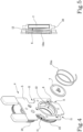
Figure 1 is a side view, with some parts in cross section to better illustrate others, of a projector with a lens unit for optical effects, according to this invention; -
Figures 2 and3 are exploded perspective views, with various components cut away to better illustrate others, of the projector with a filter unit for optical effects ofFigure 1 ;
Figure 4 is a perspective exploded view of a first lens unit of the previous drawings; -
Figure 5 is a cross section view of a portion of the first filter unit ofFigure 4 ; -
Figure 6 is a perspective exploded view of a second lens unit of the previous drawings; -
Figures 7 and 8 show front and rear perspective views, respectively, of the first and second filter units superposed and centred relative to each other; -
Figure 9 is a cross section view of a portion of the first and second filter units ofFigure 8 . - With reference to the accompanying drawings, and with particular reference to
Figures 1 to 3 , the lens unit for optical effects according to the invention may be applied on a projector, labelled 100 in its entirety, used for lighting areas dedicated to artistic events, such as theatre productions and concerts, or sports events, both outdoors and indoors. - As illustrated, the
projector 100 comprises a projector body 1 (box-shaped body) having a first end and a second end to define a longitudinal axis of extension. - The
projector 100 also comprises a light source 2 (for example, a LED unit), positioned inside theprojector body 1 close to the first end and configured for generating a light beam F along a direction of emission and in a sense of emission extending from the first end to the second end of theprojector body 1. - The
projector 100 comprises an outlet lens 3 (zoom and/or focusing lens) of the light beam F positioned at the second end of theprojector body 1. Moreover, theprojector 100 comprises at least a firstoptical filter unit 4 comprising aframe 5 having aseat 6 for housing afilter lens 7. - The
frame 5 is housed inside theprojector body 1 and interposed between thelight source 2 and theoutlet lens 3 so as to allow the light beam F to be intercepted by thefilter lens 7 in a position centred relative to the light beam F. - Again as illustrated, the
projector 100 comprises, inside theprojector body 1, abody 8 for stable positioning of the at least afirst filter unit 4. - The
positioning body 8 is equipped with magnetic attraction means 9 configured to attract and retain theframe 5 of thefirst filter unit 4 inside theprojector body 1 in the centred position. - In other words, the
filter unit 4 may be quickly housed (and picked up) manually in theprojector body 1 in the correct position through the resting on thepositioning body 8 without the need for other fixing devices inside the projector body. - The accessibility to the inner part of the
projector body 1 is given by the presence of aremovable cover 22 located on the upper part of theprojector body 1. - In light of this, the
stable positioning body 8 and thefirst filter unit 4 haverespective elements first filter unit 4 in the centred position at the stable positioning by magnetic attraction of thefirst filter unit 4 against thestable positioning body 8. - It should be noted that the
positioning body 8 is an annular element associated with inner walls of theprojector body 1. - The annular element (the geometrical shape of which makes it possible to maintain a free zone of passage of the light beam F) has a plurality of magnetic units (a series of magnets with an annular shape fixed on the positioning body 8) forming the magnetic attraction means 9 positioned along a front annular surface of the
body 8. - In light of this, see
Figure 3 , thepositioning body 8 is housed on aflange 20 in turn associated with the inner walls of theprojector body 1. Preferably, thepositioning body 8 is integral with acylinder 21 enclosing other lenses (not illustrated) positioned between thepositioning body 8 and thelight source 2. - As also illustrated in
Figures 4 and 5 , thefirst filter unit 4 has theframe 5 formed by a first portion on which theseat 6 for housing thefilter lens 7 is made and a second portion configured for its gripping and manipulating (for example, a gripping fork). - In light of this, the first portion of the
frame 5 is obtained with ferromagnetic material so as to allow the coupling of theframe 5 to thestable positioning body 8. - Preferably, the entire
first frame 5 is obtained with ferromagnetic material. Preferably, the above-mentioned reference andcoupling elements positioning body 8 and theframe 5 of thefirst filter unit 4 comprise at least one pair ofenlargements 10 projecting parallel to the longitudinal axis of extension of theprojector body 1 and towards its second end. - The enlargements (of the semi-circular protruding sectors) are formed along the outer perimeter of the
stable positioning body 8. - The reference elements also comprise at least one pair of
open slots 11 made on theframe 5 of thefirst filter unit 4 which can be coupled, by sliding, with theenlargements 10 until contact of theframe 5 with thepositioning body 8. - It should be noted that the
stable positioning body 8 has fourenlargements 10 uniformly arranged around thepositioning body 8, whilst theframe 5 of thefirst filter group 4 having fourmatching slots 11 made in pairs along corresponding side walls formed by theframe 5. - As illustrated in
Figures 4 to 9 , theframe 5 of thefirst filter group 4 comprises a flat elongate plate provided, in the first portion, with a circular opening in which is partly inserted acircular sleeve 12, which can be freely rotated and defining theseat 6 for thefilter lens 7. - The
filter lens 7 is held in thesleeve 12 by aspring 12m. - The
circular sleeve 12 is associated, externally, with manual adjustment means 13 configured to allow the variation of the angular position of thefilter lens 7 positioned inside thecircular sleeve 12 with thefirst filter unit 4 mounted in theprojector body 1. - The manual adjustment means 13 comprises a
first gear wheel 23 associated with thesleeve 12 and meshed with asecond gear wheel 24 rotatably constrained on thefirst frame 5 and reachable manually from the outside of theprojector body 1 so as to allow the rotation of thesleeve 12 and hence thefirst filter lens 7. - According to the non-limiting example illustrated in
Figure 4 , thefirst lens 7 may have an image to be projected (gobo lens). - The
projector 100 may comprise asecond filter unit 14 comprising asecond frame 15 having aseat 16 for housing asecond filter lens 17. - In the case illustrated, by way of example, the
second filter lens 17 is a coloured lens. - The
second frame 15 is housed inside theprojector body 1 and interposed between thelight source 2 and thefirst filter unit 4. - As illustrated in
Figures 6 to 9 , thesecond filter unit 14 has thesecond frame 15 formed by a first portion on which is made theseat 16 for housing thesecond filter lens 17 and a second portion configured for its gripping and manipulating (in this case formed by a single vertical gripping extension). - The
second frame 15 also comprises a flat elongate sheet and has at least the first portion obtained with ferromagnetic material so as to allow the coupling of thesecond frame 15 to thestable positioning body 8. - The
second frame 15 is preferably obtained in a single body and made from ferromagnetic material. - It should be noted that the
second filter unit 14 has means 18 for joining and centring with thefirst filter unit 4. - In light of this, the joining and centring means 18 comprise two magnetic elements 19 (two magnets) configured to attract and retain the
frame 5 of thefirst filter unit 5 in contact with thesecond filter unit 14 and with therespective lenses - As illustrated in
Figures 6 and9 , the twomagnetic elements 19 of thesecond filter unit 14 are associated with the second portion of thesecond frame 15 byrespective fixing screws 25 whosehead 25a can be coupled inrespective holes 26 present on the second portion of thefirst frame 5 of thefirst filter unit 4. - This coupling, made stable by the
magnetic elements 19, ensures centring between the twolenses - It should be noted that the
second frame 15 is equipped with four matchingopen slots 27 which can be coupled with theenlargements 10 of thepositioning body 8 during housing in theprojector body 1. - In this way, once the two
filter units projector body 1 having the certainty that the two lenses are centred on each other and relative to the light beam F. - The preset aims are achieved thanks to this lens unit for optical effects.
- The first filter unit (or primary holder) has adjustment means (by means of pair of gears) with which it is possible to obtain a manual adjustment by rotating the lens from the outside of the projector, without having to extract the filter unit and from the axis of the lens. In this way, it is possible to correct any rotation or indexing error in a short time.
- The second filter unit, which may house a second lens, is structured to be coupled to the first filter unit by means of magnets.
- The system for coupling the two units allows images, colours or both to be combined, always having the certainty of centring the lenses present.
- This modularity of the components allows a large saving in the materials having a reduced internal size.
- This modular system may be accessible through an inspection door located on the projector body, thus allowing the units to be extracted and assembled without having to mechanically remove the optical unit or the source and check simply that the projection is correct.
Claims (8)
- A lens unit for optical effects which can be used on projectors (100) generating a light beam (F), characterised in that it comprises:- a first optical filter unit (4) comprising a first frame (5) having a seat (6) for housing a first filter lens (7);- a second optical filter unit (14) comprising a second frame (15) having a seat (16) for housing a second filter lens (17);- joining and centring means (18) between the first filter unit (4) and the second filter unit (14); said joining and centring means (18) comprising at least two magnetic elements (19) associated with the second filter unit (14) and configured to attract and retain the frame (5) of the first filter unit (4) in contact with the second filter unit (14) and with the relative lenses (7, 17) centred on each other.
- The lens unit according to claim 1, wherein the at least a first filter unit (4) has the first frame (5) formed by a first portion on which the seat (6) is made for housing the filter lens (7) and a second portion configured for its gripping and handling; the first frame (5) being obtained with ferromagnetic material so as to allow the coupling of the first frame (5) to the second frame (15) of the second filter unit (14).
- The lens unit according to claim 1 or 2, wherein the second filter unit (14) has the second frame (15) formed by a first portion on which the seat (16) is made for housing the second filter lens (17) and a second portion configured for its gripping and handling; the second frame (15) being obtained with ferromagnetic material.
- The lens unit according to any one of the preceding claims, wherein the joining and centring means (18) comprise the two magnetic elements (19) of the second filter unit (14) associated with the second frame (15) by means of respective fixing screws (25) the head (25a) of which being connectable, in use, in relative holes (26) made on the first frame (5) of the first filter unit (4).
- The lens unit according to any one of the preceding claims, wherein the first frame (5) of the first filter unit (4) comprises an elongated flat plate provided, in the first portion, with a circular opening in which a circular sleeve (12) is partly inserted, freely rotatable and defining the seat (6) for the filter lens (7); the circular sleeve (12) being associated, externally, with manual adjustment members (13) configured to allow the variation of the angular position of the filter lens (7) located inside the circular sleeve (12).
- The lens unit according to claim 5, wherein the manual adjustment means (13) comprises a first gear wheel (23) associated with the sleeve (12) and meshed with a second gear wheel (24) rotatably constrained on the first frame (5) and movable manually so as to allow the rotation of the sleeve (12) and hence the first filter lens (7).
- The lens unit according to any one of the preceding claims, wherein the first frame (5) of the first filter unit (4) has four complementary open slots (11) formed in pairs along corresponding side walls formed by the frame (5).
- The lens unit according to any one of the preceding claims, wherein the second frame (15) of the second filter unit (14) consists of an elongated flat plate and having four complementary slots (27) made in pairs along corresponding side walls formed by the second frame (15).
Applications Claiming Priority (1)
| Application Number | Priority Date | Filing Date | Title |
|---|---|---|---|
| IT102023000010509A IT202300010509A1 (en) | 2023-05-24 | 2023-05-24 | LENS GROUP FOR OPTICAL EFFECTS ON PROJECTORS |
Publications (3)
| Publication Number | Publication Date |
|---|---|
| EP4468050A1 true EP4468050A1 (en) | 2024-11-27 |
| EP4468050C0 EP4468050C0 (en) | 2026-01-14 |
| EP4468050B1 EP4468050B1 (en) | 2026-01-14 |
Family
ID=88097719
Family Applications (1)
| Application Number | Title | Priority Date | Filing Date |
|---|---|---|---|
| EP24177374.6A Active EP4468050B1 (en) | 2023-05-24 | 2024-05-22 | A lens unit for optical effects |
Country Status (2)
| Country | Link |
|---|---|
| EP (1) | EP4468050B1 (en) |
| IT (1) | IT202300010509A1 (en) |
Citations (3)
| Publication number | Priority date | Publication date | Assignee | Title |
|---|---|---|---|---|
| US20070211475A1 (en) | 2006-03-08 | 2007-09-13 | Laura Sevack | Light projector accessory for recessed lighting fixtures |
| EP2414726A1 (en) | 2009-03-31 | 2012-02-08 | Robe Lighting, Inc | A spring slot&lock quick-change gobo changer system |
| KR101719300B1 (en) | 2016-12-20 | 2017-03-23 | 오용수 | Coupling structure of image lens filter for Gobo illuminator |
-
2023
- 2023-05-24 IT IT102023000010509A patent/IT202300010509A1/en unknown
-
2024
- 2024-05-22 EP EP24177374.6A patent/EP4468050B1/en active Active
Patent Citations (4)
| Publication number | Priority date | Publication date | Assignee | Title |
|---|---|---|---|---|
| US20070211475A1 (en) | 2006-03-08 | 2007-09-13 | Laura Sevack | Light projector accessory for recessed lighting fixtures |
| EP2414726A1 (en) | 2009-03-31 | 2012-02-08 | Robe Lighting, Inc | A spring slot&lock quick-change gobo changer system |
| EP2414726B1 (en) * | 2009-03-31 | 2016-05-11 | Robe Lighting, Inc | A spring slot & lock quick-change gobo changer system |
| KR101719300B1 (en) | 2016-12-20 | 2017-03-23 | 오용수 | Coupling structure of image lens filter for Gobo illuminator |
Also Published As
| Publication number | Publication date |
|---|---|
| IT202300010509A1 (en) | 2024-11-24 |
| EP4468050C0 (en) | 2026-01-14 |
| EP4468050B1 (en) | 2026-01-14 |
Similar Documents
| Publication | Publication Date | Title |
|---|---|---|
| US4745531A (en) | Lighting device with all parameters adjustable simultaneously, in particular for use as a stage light | |
| US7416313B2 (en) | Assembly for illuminating objects with light of different wavelengths | |
| US3116022A (en) | Spotlight | |
| US4811182A (en) | Color changer | |
| US6601973B2 (en) | Light effects system | |
| EP2694869B1 (en) | A dual graphic wheel for an automated luminaire | |
| EP2920507B1 (en) | Luminaire with articulated elongated light beam homogenizer | |
| EP1167868A2 (en) | Light projector, particularly for projecting light beams with variable dimensions and coloring | |
| US8408755B2 (en) | Stage lighting fixture and method of operating a stage lighting fixture | |
| JPS63126110A (en) | Lighting lamp apparatus | |
| US10145524B2 (en) | Dual graphic wheel for an automated luminaire | |
| US7736022B2 (en) | Magnetic quick-change gobo changer system | |
| US10539307B2 (en) | Lamp change system for an automated luminaire | |
| EP4468050B1 (en) | A lens unit for optical effects | |
| CN102803830A (en) | A spring slot & lock quick-change gobo changer system | |
| US5597231A (en) | Variable color light projector | |
| US12066172B2 (en) | Stage light fixture having light effect elements server | |
| EP2236910B1 (en) | An improved lens slide for an automated luminaire | |
| US20110080735A1 (en) | Stage lighting fixture | |
| CN104854400B (en) | Improved frame cover plate system for lighting apparatus | |
| US6939026B2 (en) | Shutter assembly for a luminaire | |
| EP1771010A1 (en) | Digital video projection device | |
| US20080192475A1 (en) | Illumination Device for Producing Light Effects As Well As Insert for Such an Illumination Device | |
| IT202300010500A1 (en) | PROJECTOR WITH OPTICAL FILTER GROUPS | |
| JP2018120756A (en) | Luminaire |
Legal Events
| Date | Code | Title | Description |
|---|---|---|---|
| PUAI | Public reference made under article 153(3) epc to a published international application that has entered the european phase |
Free format text: ORIGINAL CODE: 0009012 |
|
| STAA | Information on the status of an ep patent application or granted ep patent |
Free format text: STATUS: THE APPLICATION HAS BEEN PUBLISHED |
|
| AK | Designated contracting states |
Kind code of ref document: A1 Designated state(s): AL AT BE BG CH CY CZ DE DK EE ES FI FR GB GR HR HU IE IS IT LI LT LU LV MC ME MK MT NL NO PL PT RO RS SE SI SK SM TR |
|
| STAA | Information on the status of an ep patent application or granted ep patent |
Free format text: STATUS: REQUEST FOR EXAMINATION WAS MADE |
|
| 17P | Request for examination filed |
Effective date: 20250312 |
|
| GRAP | Despatch of communication of intention to grant a patent |
Free format text: ORIGINAL CODE: EPIDOSNIGR1 |
|
| STAA | Information on the status of an ep patent application or granted ep patent |
Free format text: STATUS: GRANT OF PATENT IS INTENDED |
|
| RIC1 | Information provided on ipc code assigned before grant |
Ipc: G02B 7/00 20210101AFI20250701BHEP Ipc: F21V 13/08 20060101ALI20250701BHEP Ipc: F21V 14/08 20060101ALI20250701BHEP Ipc: G02B 26/00 20060101ALI20250701BHEP Ipc: F21S 10/00 20060101ALI20250701BHEP Ipc: F21V 17/00 20060101ALI20250701BHEP Ipc: F21W 131/406 20060101ALI20250701BHEP Ipc: F21V 17/10 20060101ALI20250701BHEP |
|
| INTG | Intention to grant announced |
Effective date: 20250804 |
|
| RIN1 | Information on inventor provided before grant (corrected) |
Inventor name: DI FUSCO, MATTEO LUCIANO Inventor name: GABRIELLI, ANDREA |
|
| GRAS | Grant fee paid |
Free format text: ORIGINAL CODE: EPIDOSNIGR3 |
|
| GRAA | (expected) grant |
Free format text: ORIGINAL CODE: 0009210 |
|
| STAA | Information on the status of an ep patent application or granted ep patent |
Free format text: STATUS: THE PATENT HAS BEEN GRANTED |
|
| AK | Designated contracting states |
Kind code of ref document: B1 Designated state(s): AL AT BE BG CH CY CZ DE DK EE ES FI FR GB GR HR HU IE IS IT LI LT LU LV MC ME MK MT NL NO PL PT RO RS SE SI SK SM TR |
|
| REG | Reference to a national code |
Ref country code: CH Ref legal event code: F10 Free format text: ST27 STATUS EVENT CODE: U-0-0-F10-F00 (AS PROVIDED BY THE NATIONAL OFFICE) Effective date: 20260114 Ref country code: GB Ref legal event code: FG4D |
|
| REG | Reference to a national code |
Ref country code: DE Ref legal event code: R096 Ref document number: 602024002019 Country of ref document: DE |
|
| REG | Reference to a national code |
Ref country code: IE Ref legal event code: FG4D |
|
| U01 | Request for unitary effect filed |
Effective date: 20260203 |
|
| U07 | Unitary effect registered |
Designated state(s): AT BE BG DE DK EE FI FR IT LT LU LV MT NL PT RO SE SI Effective date: 20260209 |
|
| U20 | Renewal fee for the european patent with unitary effect paid |
Year of fee payment: 3 Effective date: 20260327 |