EP4468035A1 - Measurement device - Google Patents
Measurement device Download PDFInfo
- Publication number
- EP4468035A1 EP4468035A1 EP22920463.1A EP22920463A EP4468035A1 EP 4468035 A1 EP4468035 A1 EP 4468035A1 EP 22920463 A EP22920463 A EP 22920463A EP 4468035 A1 EP4468035 A1 EP 4468035A1
- Authority
- EP
- European Patent Office
- Prior art keywords
- exposure
- measurement
- light
- area
- areas
- Prior art date
- Legal status (The legal status is an assumption and is not a legal conclusion. Google has not performed a legal analysis and makes no representation as to the accuracy of the status listed.)
- Pending
Links
Images






Classifications
-
- G—PHYSICS
- G01—MEASURING; TESTING
- G01S—RADIO DIRECTION-FINDING; RADIO NAVIGATION; DETERMINING DISTANCE OR VELOCITY BY USE OF RADIO WAVES; LOCATING OR PRESENCE-DETECTING BY USE OF THE REFLECTION OR RERADIATION OF RADIO WAVES; ANALOGOUS ARRANGEMENTS USING OTHER WAVES
- G01S7/00—Details of systems according to groups G01S13/00, G01S15/00, G01S17/00
- G01S7/48—Details of systems according to groups G01S13/00, G01S15/00, G01S17/00 of systems according to group G01S17/00
- G01S7/481—Constructional features, e.g. arrangements of optical elements
- G01S7/4814—Constructional features, e.g. arrangements of optical elements of transmitters alone
- G01S7/4815—Constructional features, e.g. arrangements of optical elements of transmitters alone using multiple transmitters
-
- G—PHYSICS
- G01—MEASURING; TESTING
- G01S—RADIO DIRECTION-FINDING; RADIO NAVIGATION; DETERMINING DISTANCE OR VELOCITY BY USE OF RADIO WAVES; LOCATING OR PRESENCE-DETECTING BY USE OF THE REFLECTION OR RERADIATION OF RADIO WAVES; ANALOGOUS ARRANGEMENTS USING OTHER WAVES
- G01S17/00—Systems using the reflection or reradiation of electromagnetic waves other than radio waves, e.g. lidar systems
- G01S17/02—Systems using the reflection of electromagnetic waves other than radio waves
- G01S17/06—Systems determining position data of a target
- G01S17/08—Systems determining position data of a target for measuring distance only
- G01S17/10—Systems determining position data of a target for measuring distance only using transmission of interrupted, pulse-modulated waves
-
- G—PHYSICS
- G01—MEASURING; TESTING
- G01S—RADIO DIRECTION-FINDING; RADIO NAVIGATION; DETERMINING DISTANCE OR VELOCITY BY USE OF RADIO WAVES; LOCATING OR PRESENCE-DETECTING BY USE OF THE REFLECTION OR RERADIATION OF RADIO WAVES; ANALOGOUS ARRANGEMENTS USING OTHER WAVES
- G01S17/00—Systems using the reflection or reradiation of electromagnetic waves other than radio waves, e.g. lidar systems
- G01S17/02—Systems using the reflection of electromagnetic waves other than radio waves
- G01S17/06—Systems determining position data of a target
- G01S17/42—Simultaneous measurement of distance and other co-ordinates
-
- G—PHYSICS
- G01—MEASURING; TESTING
- G01S—RADIO DIRECTION-FINDING; RADIO NAVIGATION; DETERMINING DISTANCE OR VELOCITY BY USE OF RADIO WAVES; LOCATING OR PRESENCE-DETECTING BY USE OF THE REFLECTION OR RERADIATION OF RADIO WAVES; ANALOGOUS ARRANGEMENTS USING OTHER WAVES
- G01S7/00—Details of systems according to groups G01S13/00, G01S15/00, G01S17/00
- G01S7/48—Details of systems according to groups G01S13/00, G01S15/00, G01S17/00 of systems according to group G01S17/00
- G01S7/481—Constructional features, e.g. arrangements of optical elements
- G01S7/4817—Constructional features, e.g. arrangements of optical elements relating to scanning
-
- G—PHYSICS
- G01—MEASURING; TESTING
- G01S—RADIO DIRECTION-FINDING; RADIO NAVIGATION; DETERMINING DISTANCE OR VELOCITY BY USE OF RADIO WAVES; LOCATING OR PRESENCE-DETECTING BY USE OF THE REFLECTION OR RERADIATION OF RADIO WAVES; ANALOGOUS ARRANGEMENTS USING OTHER WAVES
- G01S7/00—Details of systems according to groups G01S13/00, G01S15/00, G01S17/00
- G01S7/48—Details of systems according to groups G01S13/00, G01S15/00, G01S17/00 of systems according to group G01S17/00
- G01S7/483—Details of pulse systems
- G01S7/484—Transmitters
-
- G—PHYSICS
- G01—MEASURING; TESTING
- G01S—RADIO DIRECTION-FINDING; RADIO NAVIGATION; DETERMINING DISTANCE OR VELOCITY BY USE OF RADIO WAVES; LOCATING OR PRESENCE-DETECTING BY USE OF THE REFLECTION OR RERADIATION OF RADIO WAVES; ANALOGOUS ARRANGEMENTS USING OTHER WAVES
- G01S17/00—Systems using the reflection or reradiation of electromagnetic waves other than radio waves, e.g. lidar systems
- G01S17/88—Lidar systems specially adapted for specific applications
- G01S17/89—Lidar systems specially adapted for specific applications for mapping or imaging
- G01S17/894—Three-dimensional [3D] imaging with simultaneous measurement of time-of-flight at a two-dimensional [2D] array of receiver pixels, e.g. time-of-flight cameras or flash lidar
-
- G—PHYSICS
- G01—MEASURING; TESTING
- G01S—RADIO DIRECTION-FINDING; RADIO NAVIGATION; DETERMINING DISTANCE OR VELOCITY BY USE OF RADIO WAVES; LOCATING OR PRESENCE-DETECTING BY USE OF THE REFLECTION OR RERADIATION OF RADIO WAVES; ANALOGOUS ARRANGEMENTS USING OTHER WAVES
- G01S17/00—Systems using the reflection or reradiation of electromagnetic waves other than radio waves, e.g. lidar systems
- G01S17/88—Lidar systems specially adapted for specific applications
- G01S17/93—Lidar systems specially adapted for specific applications for anti-collision purposes
- G01S17/931—Lidar systems specially adapted for specific applications for anti-collision purposes of land vehicles
Definitions
- the present disclosure relates to a measurement device.
- Patent Literature 1 noise due to light other than reflected light is reduced by operating an imaging sensor near where the reflected light returns.
- Patent Literature 1 JP2019-191126A
- a measurement target is a vehicle
- light light reflected by the target
- a road surface at a place where the road surface is wet due to rain or the like or a place where the road surface is smoothly paved such as a parking lot.
- Accurate measurement may not be performed due to influence of this road surface reflection.
- influence of the light other than the reflected light can be reduced, but when positions of a light source and the imaging sensor are misaligned, an arrival position of the reflected light shifts depending on a distance to a target. Therefore, there is a possibility of exposure to light reflected from a road surface.
- An object of the present disclosure is to reduce influence of road surface reflection.
- a measurement device including: a light emitting unit configured to emit light to each of a plurality of measurement areas at different heights; an exposure unit having a plurality of exposure areas respectively corresponding to the measurement areas at different heights, and exposed to reflected light from the measurement areas by a plurality of light receiving elements respectively provided for the exposure areas; and a distance calculation unit configured to calculate a distance to a target in the measurement areas based on an exposure result of the exposure unit.
- influence of road surface reflection can be reduced.
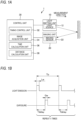
- FIG. 1A is a diagram showing a configuration of a measurement device 1.
- the measurement device 1 shown in FIG. 1A is a time-of-flight (ToF) device that measures a distance to an object in front.
- ToF time-of-flight
- an indirect ToF camera is used.
- Such a measurement device 1 can remove influence of fog or rain, and perform imaging and measurement even in bad weather.
- the measurement device 1 is provided in a vehicle, for example.
- the measurement device 1 includes a light emitting unit 10, an imaging unit 20, and a control unit 30.
- the light emitting unit 10 emits (projects) light to a space to be imaged.
- the light emitting unit 10 controls light emission according to an instruction from the control unit 30.
- the light emitting unit 10 includes a light source 12 and a projecting optical system (not shown) that emits light generated by the light source 12.
- the light source 12 includes light emitting elements 122 (to be described later).
- the light source 12 emits pulsed laser light under the control of the control unit 30.
- this pulsed light is also referred to as a light emission pulse.
- the light source 12 will be described in detail later.
- the imaging unit 20 (indirect ToF camera) performs imaging based on exposure to light reflected by a target of distance measurement.
- the imaging unit 20 includes an imaging sensor 22 and an exposure optical system (not shown) that guides incident (exposure) light to the imaging sensor 22.
- the imaging unit 20 corresponds to an "exposure unit”.
- the imaging sensor 22 images an object to be imaged according to an instruction from the control unit 30 and outputs image data obtained by imaging to an image acquisition unit 34 of the control unit 30.
- a value (pixel data) of each pixel constituting the image data indicates a signal value corresponding to an exposure amount.
- the imaging sensor 22 will be described in detail later.
- the control unit 30 controls the measurement device 1.
- the control unit 30 is implemented by a hardware configuration such as an element or a circuit, such as a memory or a CPU.
- the control unit 30 implements a predetermined function by the CPU executing a program stored in the memory.
- FIG. 1A shows various functions implemented by the control unit 30.
- the control unit 30 includes a timing control unit 32, the image acquisition unit 34, a time calculation unit 36, and a distance calculation unit 38.
- the timing control unit 32 controls a light emission timing of the light emitting unit 10 and an exposure timing of the imaging unit 20.
- the light emission timing and the exposure timing will be described later.
- the image acquisition unit 34 acquires image data from the imaging sensor 22 of the imaging unit 20.
- the image acquisition unit 34 includes a memory (not shown) that stores the acquired image data.
- the time calculation unit 36 calculates an arrival time (time of flight of light: ToF) from when the light source 12 of the light emitting unit 10 emits light until the reflected light reaches the imaging sensor 22 of the imaging unit 20.
- the distance calculation unit 38 calculates a distance based on an exposure result of the imaging sensor 22 and the arrival time of the light. As will be described later, a distance image can be acquired by calculating a distance for each pixel.
- FIG. 1B is a diagram showing light emission timings and exposure timings.
- FIG. 2 is a diagram showing distance image creation using the indirect ToF.
- the control unit 30 causes the light emitting unit 10 to emit a light emission pulse.
- a width of the light emission pulse (hereinafter, pulse width) is Lw.
- the control unit 30 causes the imaging sensor 22 of the imaging unit 20 to be exposed to the reflected light after a time Tdelay from emission of the light emission pulse.
- An exposure period is set based on the delay time Tdelay and an exposure width Gw.
- the exposure period is a period in which an exposure level is a high level (H level).
- the time Tdelay is a time (delay time) from the emission of the light emission pulse to a start of the exposure period.
- the delay time Tdelay is set according to a distance to a measurement target region. That is, by setting a short time from when the light emitting unit 10 emits the light emission pulse until the imaging sensor 22 starts exposure, an image of a target (object that reflects light) in a short distance region can be acquired. Conversely, by setting a long time from when the light emitting unit 10 emits the light emission pulse until the imaging sensor 22 starts exposure, an image of a target in a long distance region can be acquired.
- the exposure width Gw is a width of the exposure period (that is, a period from a start of the exposure to an end of the exposure).
- the width of the exposure period defines a length of the measurement target region in a measurement direction. Therefore, the smaller the exposure width Gw is, the higher a distance resolution becomes.
- FIG. 2 different exposure periods are set according to the distance to the measurement target region.
- Four regions are shown in FIG. 2 for simplicity, but the number N of regions is actually greater than four.
- the light emission and the exposure are repeated a plurality of times at a cycle Tp shown in FIG. 1B .
- This is for storing charges in the imaging sensor 22 to be described later.
- a target object that reflects light
- the image for each region may be referred to as a "range image”.
- a value (image data) of each pixel constituting the image indicates a signal value corresponding to an exposure amount.
- the measurement device 1 acquires image data on a plurality of regions of different distances, and can acquire a distance image indicating a distance to a target based on a plurality of pieces of acquired image data.
- This distance image may be referred to as a "frame”.
- a multi-tap (specifically, four taps) CMOS image sensor is used as the imaging sensor 22.
- the imaging sensor 22 is not limited to the multi-tap CMOS image sensor.
- FIG. 3 is a diagram showing a configuration example of the imaging sensor 22.
- a plurality of pixels 221 are two-dimensionally arranged (for example, 640 ⁇ 480) in the imaging sensor 22.
- One light receiving element PD and a plurality of (here, four) signal reading units RU1 to RU4 corresponding to the one light receiving element PD are provided in each pixel 221.
- Signal output units SO1 to SO4 are provided for the signal reading units RU1 to RU4, respectively.
- the signal reading units RU1 to RU4 have the same configuration (only reference numerals of components are different).
- the signal output units SO1 to SO4 have the same configuration. In the following description, the signal reading units and the signal output units will be mainly described using the signal reading unit RU1 and the signal output unit SO1.
- the light receiving element PD is an element (for example, a photodiode) that generates charges corresponding to an exposure amount.
- the signal reading unit RU1 includes a storage unit CS1, a transistor G1, a reset transistor RT1, a source follower transistor SF1, and a selection transistor SL1.
- the storage unit CS1 stores the charges generated by the light receiving element PD, and includes a storage capacitor C1 and a floating diffusion FD1.
- the transistor G1 is provided between the light receiving element PD and the storage unit CS1.
- the transistor G1 is turned on in a predetermined exposure period (for example, an exposure period 1 to be described later) and supplies the charges generated by the light receiving element PD to the storage unit CS1 based on an instruction of the timing control unit 32 of the control unit 30.
- transistors G2 to G4 supply the charges generated by the light receiving element PD to the storage units CS2 to CS4, respectively, based on instructions from the timing control unit 32. That is, the transistors G1 to G4 distribute the charges generated by the light receiving element PD to the storage units CS1 to CS4 according to the exposure period.
- the charges are repeatedly stored in each storage unit according to the number n of times of repetition.
- the charges stored in each storage unit correspond to an amount of light to which the light receiving element PD is exposed in each exposure period.
- the signal output unit SO1 When the selection transistor SL1 of the signal reading unit RU1 is selected, the signal output unit SO1 outputs a signal value corresponding to charges stored in the storage unit CS1.
- the signal output unit SO1 includes an amplification circuit ZF1 that amplifies an output of the signal reading unit RU1 and an A/D conversion circuit HK1 that converts an output (analog signal) of the amplification circuit ZF 1 into a digital signal.
- the signal output unit SO1 converts the charges (exposure amount in the exposure period) stored in the storage unit CS1 into a signal value (digital signal) corresponding to the charges and outputs the signal value to the image acquisition unit 34 of the control unit 30.
- the signal value (digital signal) based on the charges stored in the storage unit CS1 is a signal value according to an exposure amount in the exposure period.
- four regions can be measured by imaging once. That is, four range images are obtained by imaging once.
- the number of (here, four) range images obtained by imaging once may be referred to as a "subframe”.
- a plurality of regions (here, four regions) measured by imaging once may be referred to as a "zone”.
- control unit 30 causes the light emitting unit 10 to emit light at the cycle Tp (see FIG. 1B ), and controls an exposure timing of the imaging unit 20 according to a light emission timing.
- image acquisition unit 34 acquires an image (image data) captured by the imaging unit 20 at each exposure timing.
- images of a zone 1 is acquired. That is, the timing control unit 32 causes the imaging sensor 22 of the imaging unit 20 perform exposure for each pixel of an image in exposure periods 1 to 4 (see FIG. 4 ) delayed from the light emission timing.
- the timing control unit 32 causes the exposure to be repeatedly performed for each cycle Tp, and stores the charges in the storage units CS1 to CS4.
- the image acquisition unit 34 acquires signal values corresponding to charges stored in the storage units CS1 to CS4 via the signal output units SO1 to SO4. Then, the control unit 30 writes image data on acquired range images (subframes) of the regions 1 to 4 into an image memory of the image acquisition unit 34.
- the control unit 30 acquires images of the zone 2 (regions 5 to 8). Then, the control unit 30 writes image data on range images (subframes) of the regions 5 to 8 into the image memory of the image acquisition unit 34.
- the delay time Tdelay from a light emission timing in the zone 2 (regions 5 to 8) is set to be longer than that in a case of the zone 1 (regions 1 to 4). As described above, the number of times of repetition (the number of times of charge accumulation) is set to increase as the measurement target region becomes further away.
- light emission pulses (light emission timings) are different in the region 4 and the region 5
- exposure periods of the region 4 and the region 5 are consecutive with the light emission pulse as a reference. In this way, the consecutive exposure periods are not limited to exposure periods having the same light emission timing, and may include exposure periods having different light emission timings.
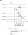
- FIG. 4 is a diagram showing a relationship between light emission and exposure in a case of four taps.
- a pulse width of a light emission pulse is Lw.
- a pulse width of the reflected light is also denoted by Lw.
- exposure 1 to 4 is set.
- a width (exposure width) of each exposure period of the exposure 1 to 4 is the same as the pulse width Lw of the light emission pulse.
- the exposure period is a period in which an exposure level in the drawing is a high level (H level).
- H/L levels of the exposure 1 to 4 indicate whether the transistors G1 to G4 in FIG. 3 are turned on or off.
- the transistor G1 is turned on in an H-level exposure period 1 of the exposure 1, and the charges generated by the light receiving element PD is stored in the storage capacitor C1 of the storage unit CS1.
- the reflected light is used for exposure in an exposure period 2 and an exposure period 3 (the reflected light may reach a period different from the exposure period 2 and the exposure period 3, and for example, the reflected light may be used for exposure in the exposure period 1 and the exposure period 2).
- the reflected light is used for exposure in the exposure period 1, and the charges are not stored in the storage unit CS1 for the pixel 221 of the imaging sensor 22 (a signal value S 1 acquired in the exposure period 1 is zero).
- the exposure period 2 corresponding to a region (region 2) next to the region 1 is set in the exposure 2.
- the pixel 221 of the imaging sensor 22 acquires a signal value S 2 corresponding to an exposure amount of the reflected light in the exposure period 2.
- the exposure period 3 corresponding to a region (region 3) next to the region 2 is set in the exposure 3.
- the pixel 221 of the imaging sensor 22 acquires a signal value S 3 corresponding to an exposure amount of the reflected light in the exposure period 3.
- An exposure period 4 corresponding to a region (region 4) next to the region 3 is set in the exposure 4.
- the reflected light is used for exposure in the exposure period 4, and the charges are not stored in the storage unit CS4 for the pixel 221 of the imaging sensor 22 (a signal value S 4 acquired in the exposure period 4 is zero).
- FIG. 4 is shown based on charges in once exposure for description, but actually a signal value S i (here, S 1 to S 4 ) is a signal value according to charges (corresponding to an exposure amount) stored by repeating the exposure for the number n of times of repetition.
- the signal output units SO1 to SO4 for the pixel 221 of the imaging sensor 22 respectively output signal values S 1 to S 4 according to the charges stored in the storage units CS1 to CS4.
- the signal values S 1 to S 4 correspond to values (pixel data) of pixels constituting image data on images (range images) of the regions 1 to 4, respectively.
- the image acquisition unit 34 of the control unit 30 acquires the signal values S 1 to S 4 (signal values according to the charges stored in the storage units CS1 to CS4) of the pixels 221 from the imaging sensor 22. Accordingly, the image acquisition unit 34 acquires the image data on the regions 1 to 4. Similarly, the image acquisition unit 34 acquires the images up to the region N (images of all the regions).
- the time calculation unit 36 of the control unit 30 calculates an arrival time Tx of the reflected light. Specifically, first, the time calculation unit 36 specifies a signal value S of exposure to the reflected light from the signal values S 1 to S 4 (signal values S 1 to S N ). For example, the time calculation unit 36 specifies a signal value of a signal corresponding to two consecutive exposure periods and having the highest exposure amount. For example, when a signal value corresponding to an exposure period i in which the reflected light starts exposure is S i , two signal values S i and S i+1 are specified.
- the signal values S 2 and S 3 correspond to the signal values S i and S i+1 of exposure to the reflected light.
- the time calculation unit 36 uses the signal values S i and S i+1 to calculate the flight time (hereinafter also referred to as an arrival time) Tx of the light by the following Equation (1).
- Tx T i + 1 ⁇ Lw ⁇ Si / S i + S i + 1
- the distance calculation unit 38 calculates the distance L to the target by Equation (2).
- the distance calculation unit 38 according to the present embodiment calculates the distance L to the target in a measurement area for each measurement area to be described later.
- FIG. 5A is a diagram showing an area configuration of the light source 12 according to the present embodiment.
- FIG. 5B is a diagram showing an area configuration of the imaging sensor 22 according to the present embodiment. In FIG. 5B , each pixel is not shown.
- each area is shown to correspond to a measurement area ( FIG. 7 ) to be described later. Since an image is vertically inverted by an optical system (lens), an upper-lower relationship is opposite to that of the measurement area ( FIG. 7 ).
- a horizontal direction is a direction orthogonal to a vertical direction and is a direction parallel to a road surface.
- a direction (for example, a left-right direction) orthogonal to the measurement direction (for example, a front-back direction) in FIGs. 1 and 2 is shown.
- the light source 12 includes a light source substrate 121 and a plurality of light emitting elements 122.
- the light source substrate 121 is a plate-shaped member on which the light emitting elements 122 are arranged.
- the light source substrate 121 has a surface facing the measurement direction, and the plurality of light emitting elements 122 are arranged on the surface.
- the light emitting element 122 is an element that emits light when supplied with a drive current. Similarly to the pixels 221 of the imaging sensor 22, the plurality of light emitting elements 122 are two-dimensionally arranged on the surface of the light source substrate 121. More specifically, the plurality of light emitting elements 122 are arranged to be divided into five areas (light emitting areas 1 to 5) in an upper-lower direction so as to correspond to a plurality of (five in the present embodiment) measurement areas (to be described later) at different heights in the vertical direction. In other words, the light source 12 (light emitting unit 10) according to the present embodiment has five light emitting areas respectively corresponding to five measurement areas at different heights.
- a light emitting area 1 corresponds to the lowest measurement area 1 among the five measurement areas.
- a light emitting area 2 corresponds to a measurement area 2 above the measurement area 1.
- light emitting areas 3 to 5 correspond to measurement areas 3 to 5, respectively.
- the light emitting elements 122 are arranged in the horizontal direction (left-right direction).
- the control unit 30 causes the light emitting elements 122 to emit light for each of the plurality of light emitting elements 122 (areas) arranged in the horizontal direction. Accordingly, the light source 12 (light emitting unit 10) can emit light to the measurement area corresponding to each light emitting area.
- a method of emitting light to each measurement area is not limited to the above-described method.
- a method scanning method
- a plurality of light emitting elements arranged in the horizontal direction emit light by moving in a height direction (vertical direction) according to switching of a measurement area.
- the imaging sensor 22 has five exposure areas (exposure areas 1 to 5) corresponding to five measurement areas (to be described later) at different heights in the vertical direction.
- the plurality of pixels 221 in other words, the plurality of light receiving elements PD
- the imaging unit 20 is exposed to reflected light from a corresponding measurement area by the plurality of light receiving elements PD provided for each exposure area.
- the exposure area 1 is an imaging area, and in this case, reflected light from the corresponding measurement area 1 is used for exposure.
- an arrival range of the reflected light is wider than the exposure area. Accordingly, the reflected light can also be used for exposure in the pixel 221 (light receiving element PD) at an end of the exposure area.
- the light source and the imaging sensor are arranged at different heights, there is a possibility that the imaging sensor cannot be exposed due to influence of the distance to the target.
- FIG. 6A is a diagram showing a case where a light source and a camera (imaging sensor) are provided at different heights.
- a light source and a camera imaging sensor
- FIG. 6A shows a case where a light source and a camera (imaging sensor) are provided at different heights.
- a setting is made such that light is emitted from the light source to a target A at a certain distance and the camera (imaging sensor) at a different height is exposed to the reflected light
- an arrival position (height) of reflected light of the light emitted to a target B at a different distance deviates from a position of the imaging sensor.
- FIG. 6B is a diagram showing a positional relationship between the light source 12 and the imaging sensor 22 according to the present embodiment.
- the light source 12 and the imaging sensor 22 are disposed at the same height.
- the imaging sensor 22 is provided at the same height as the light source 12 in the imaging unit 20 in the drawing. More specifically, an light emitting area of the light source 12 and an exposure area of the imaging sensor 22 corresponding to the light emitting area are disposed at the same height. Accordingly, a correspondence relationship among the light emitting area, a measurement area, and the exposure area is not influenced by a distance to a target. That is, regardless of the distance to the target, the reflected light of light emitted from the light emitting area of the light source 12 (light that reaches the target and reflected thereby) can be used for exposure in the corresponding exposure area of the imaging sensor 22.
- two light sources 12 are provided to sandwich the imaging sensor 22 in the horizontal direction (at the same height as the imaging sensor 22).
- the present disclosure is not limited thereto, and either one may be used (one light source 12 may correspond to one imaging sensor 22). Two or more light sources 12 may correspond to one imaging sensor 22.
- FIG. 13 is a diagram showing measurement according to a comparative example.
- light emitting elements are two-dimensionally arranged similarly to the light source 12 according to the present embodiment
- pixels (light receiving elements) are two-dimensionally arranged similarly to the imaging sensor 22 according to the present embodiment.
- the light source irradiates a measurement target (here, a vehicle) with light by full light emission, and a camera (imaging sensor) is exposed to the reflected light by overall surface exposure.
- a measurement target here, a vehicle
- a camera imaging sensor
- the reflected light from the target may be further reflected by the road surface, and the camera (imaging sensor) may be exposed to the reflected light (reflected light via the road surface).
- a reflected image of the vehicle is reflected by the reflected light via the road surface, and thus accurate measurement may not be performed. That is, a pixel (light receiving element) that should not actually be exposed to reflected light may be exposed to light reflected from the road surface, and charges may be stored in a storage unit for the pixel. Accordingly, an image showing the vehicle at a position on the road surface may be generated in a distance image.
- FIG. 7 is a diagram showing a measurement method using the measurement device 1 according to the present embodiment.
- the measurement device 1 according to the present embodiment is divided into five areas (measurement areas 1 to 5) at different heights in the vertical direction, and performs measurement by sequentially switching for each measurement area.
- the five measurement areas are referred to as a measurement area 1, a measurement area 2, ..., and a measurement area 5 in this order from a lower side.
- a non-hatched white area is a measurement target area.
- the measurement area 1 is a measurement target.
- the measurement area 3 is a measurement target.
- the control unit 30 performs switching of the measurement area (switching of light emission and exposure).
- the memory of the control unit 30 stores in advance a program for executing switching such as an order and a timing for switching of the measurement area.
- the control unit 30 causes only the light emitting elements 122 in the light emitting area 1 corresponding to the measurement area 1 to emit light, and does not cause the light emitting elements 122 in the light emitting areas 2 to 5 to emit light. That is, the light emitting unit 10 irradiates only the measurement area 1 with light, and does not irradiate other measurement areas (measurement areas 2 to 5) with light. In a case of the drawing, since the vehicle is located in the measurement areas 3 to 5, the vehicle is not irradiated with light (light is irradiated only on the road surface).
- the control unit 30 causes only the pixels 221 (light receiving elements PD) of the exposure area 1 corresponding to the measurement area 1 to be exposed and does not cause the light receiving elements PD of the exposure areas 2 to 5 to be exposed (or among the five exposure areas 1 to 5 of the imaging unit 20, the control unit 30 acquires signals of only the pixels 221 of the exposure area 1 corresponding to the measurement area 1 and does not acquire signals of the pixels 221 of the exposure areas 2 to 5). That is, the imaging unit 20 images only the measurement area 1 and does not image other measurement areas (measurement areas 2 to 5).
- the imaging unit 20 When measuring the measurement area 3 (or the measurement areas 4 and 5), even if there is the reflected light via the road surface in the comparative example ( FIG. 13 ), the imaging unit 20 does not measure the measurement areas 1 and 2, and thus the reflected light via the road surface is not used for exposure (there is no influence of the reflected light via the road surface).
- FIG. 8A is a diagram showing an operation of the light emitting unit 10 (light source 12).
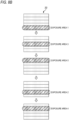
- FIG. 8B is a diagram showing an operation of the imaging unit 20 (imaging sensor 22).
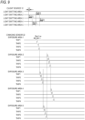
- FIG. 9 is a timing chart showing a relationship between light emission and exposure according to the present embodiment. A relationship between light emission and exposure in each area is the same as that in FIG. 4 (TAP1 to TAP4 correspond to the exposure 1 to 4 in FIG. 4 ).
- FIG. 9 shows a relationship between once light emission and exposure for each area for description, but actually, the light emission and the exposure are repeated at a predetermined cycle (corresponding to the cycle Tp in FIG. 1B ).
- a predetermined cycle corresponding to the cycle Tp in FIG. 1B .
- four different taps of exposure (measurement for four regions) with different delay time from a light emission pulse are shown, but actually, similar measurement is performed by further increasing the delay time from generation of the light emission pulse, and the measurement is performed for all the regions (regions 1 to N).
- the measurement device 1 performs light emission and exposure at different timings for each area. Specifically, as shown in FIG. 7 , measurement is performed in an order of the measurement area 1 ⁇ the measurement area 3 ⁇ the measurement area 5 ⁇ the measurement area 2 ⁇ the measurement area 4.
- control unit 30 causes the light emission pulse to be emitted from the light emitting area 1 corresponding to the measurement area 1 for a period of the pulse width Lw. Accordingly, the light emitting area 1 (light emitting elements 122) emits light as shown in FIG. 8A .
- the control unit 30 causes the light emitting area 3 corresponding to the measurement area 3 to emit a light emission pulse having the pulse width Lw. Accordingly, the light emitting elements 122 in the light emitting area 3 emit light as shown in FIG. 8A .
- a reason why a light emission start timing of the light emitting area 3 is set to be four times the pulse width (Lw) with respect to a light emission start timing of the light emitting area 1 is that it takes a time four times (four taps) the exposure width Gw (here, Lw) when the imaging unit 20 performs exposure for one measurement area.
- control unit 30 causes the light emission pulse to be emitted from the light emitting area 5 ⁇ the light emitting area 2 ⁇ the light emitting area 4 every time 4Lw elapses.
- the control unit 30 causes the exposure area 1 of the imaging sensor 22 to be exposed after a predetermined time (after a time corresponding to a region to be measured elapses) since the light emitting area 1 emits the light emission pulse (see FIG. 8B ).
- the control unit 30 first turns on the transistor G1 for each pixel 221 in the exposure area 1 of the imaging sensor 22 (TAP1 is set to the H level), and stores charges generated by the light receiving element PD in the storage unit CS 1. Thereafter, as shown in FIG. 9 , the control unit 30 turns on the transistors G2, G3, and G4 in order every time the exposure width Gw elapses, and switches the storage unit CS that stores the charges. Accordingly, charges corresponding to exposure amounts of the four regions at different distances in the measurement area 1 are stored in the storage units CS for the exposure area 1 of the imaging sensor 22.
- the control unit 30 After exposure in the exposure area 1 is completed (and after a predetermined time elapses since the light emitting elements 122 in the light emitting area 3 emit light), the control unit 30 causes the exposure area 3 to be exposed to reflected light of the light emitted from the light emitting area 3.
- the exposure operation is the same as that for the exposure area 1, and description thereof will be omitted.
- control unit 30 performs exposure in an order of the exposure area 5 ⁇ the exposure area 2 ⁇ the exposure area 4.
- the time calculation unit 36 calculates the arrival time Tx of the reflected light in each measurement area by Equation (1).
- the distance calculation unit 38 calculates the distance L to the target in each measurement area by Equation (2).
- the reflected light of the light emission pulse emitted before the measurement area 3 is measured may be used for exposure after measurement of the measurement area 4 is started. This is because a range including the measurement area 3 is irradiated with light (the measurement area 4 is also irradiated with light) when measuring the measurement area 3. In this way, when two measurement areas before and after switching are adjacent to each other, the two measurement areas may be influenced by light emission pulses emitted to the adjacent areas.
- control unit 30 performs control such that two measurement areas before and after switching are not adjacent to each other.
- the control unit 30 causes the measurement area 5 to be measured after the measurement area 3 is measured. Accordingly, it is possible to reduce influence of adjacent measurement areas and improve measurement accuracy.
- the control unit 30 starts light emission of the light emitting area 3 after light emission of the light emitting area 1 and before exposure of the exposure area 1.
- the control unit 30 starts light emission of the light emitting area 5 after the light emission of the light emitting area 3 and before exposure of the exposure area 3.
- the control unit 30 starts light emission of a light emitting area corresponding to a next measurement area after light emission of a light emitting area corresponding to a certain measurement area and before exposure of an exposure area corresponding to the measurement area. Accordingly, a measurement time can be shortened.
- the light emission corresponding to the next measurement area may be performed after light emission and exposure corresponding to the certain measurement area are completed.
- FIG. 10 is a diagram showing a relationship between imaging and reading.
- an imaging period is a period in which charges are stored in the storage units CS1 to CS4 for each pixel 221 of the imaging sensor 22. In this period, an operation of light emission and exposure as shown in FIG. 9 is repeated.
- a reading period is a period in which a signal value according to the charges stored in the storage units CS1 to CS4 for each pixel 221 is output.
- the charges stored in the storage units CS1 to CS4 are AD-converted by A/D conversion circuits HK1 to HK4 through amplification circuits ZF1 to ZF4, respectively.
- AD conversion is performed for each horizontal line arranged in the horizontal direction among the plurality of two-dimensionally arranged pixels 211. For example, each horizontal line is AD-converted and read in an order from an upper side to a lower side or from the lower side to the upper side. During this reading period, no new imaging can be performed.
- the overall surface exposure When the overall surface exposure is performed as in the comparative example, it takes time to read all horizontal lines (all pixels) of the imaging sensor 22 (it takes a time equivalent to five times the reading period shown in FIG. 10 ). During the reading period, no new imaging can be performed.
- the imaging sensor 22 performs exposure and reading for each of the five exposure areas. Therefore, the number of pixels to be read once is 1/5 of that in the case of the overall surface exposure. Thus, once reading period (output time) can be shortened.
- the measurement areas are not adjacent before and after the switching of the measurement area.
- the present disclosure is not limited thereto, and the measurement areas may be adj acent to each other before and after the switching of the measurement area.
- FIG. 11 is a timing chart showing an example of a case where measurement areas are adjacent to each other before and after switching.
- the control unit 30 causes the light source 12 to emit light in an order of the light emitting area 1 ⁇ the light emitting area 2 ⁇ the light emitting area 3 ⁇ the light emitting area 4 ⁇ the light emitting area 5. That is, the control unit 30 sequentially switches a measurement area to be irradiated with light such that the measurement area goes from the lower side to the upper side. Accordingly, the control unit 30 switches an area of the imaging sensor 22 that is exposed to the reflected light in an order of the exposure area 1 ⁇ the exposure area 2 ⁇ the exposure area 3 ⁇ the exposure area 4 ⁇ the exposure area 5.
- an interval between light emission timings of the light emitting areas is preferably longer than that in a case where the measurement areas are not adjacent to each other ( FIG. 9 ) (in the drawing, an interval is 1 ⁇ sec). This is to reduce the influence of the adjacent areas.
- the measurement may be influenced by reflected light from a road surface. By performing the measurement from the lower side to the upper side, such influence can be reduced.
- the measurement is performed in all the measurement areas (measurement areas 1 to 5), but for example, when measuring a distant target, only a specific area may be measured by narrowing down the measurement areas.
- FIGs. 12A and 12B are diagrams showing narrowing-down of measurement areas.
- a vehicle as a measurement target is located farther away than in a case of FIG. 7 .
- the vehicle is located farther away.
- the measurement target (vehicle) is not included in an upper end portion (measurement area 5) and a lower end portion (measurement area 1) among the measurement areas 1 to 5. Therefore, the control unit 30 performs control so as to measure the measurement area 2 to 4 located at a central portion among the measurement areas 1 to 5 without measuring the measurement areas 1 and 5 located at end portions among the measurement areas 1 to 5. That is, the control unit 30 causes the light emitting areas 2 to 4 of the light source 12 to sequentially emit light and causes the corresponding exposure areas 2 to 4 of the imaging sensor 22 to be sequentially exposed. In this case, the measurement areas 2 to 4 correspond to the "specific area". Accordingly, the frame rate can be improved by reducing the measurement target area.
- the control unit 30 performs control so as to measure only the measurement area 3 located at a center among the measurement areas 1 to 5 without measuring the measurement areas 1, 2, 4, and 5 located at end portions among the measurement areas 1 to 5. That is, the control unit 30 causes only the light emitting area 3 of the light source 12 to emit light and causes only the exposure area 3 of the imaging sensor 22 to be exposed. In this case, the measurement area 3 corresponds to the "specific area". Accordingly, the frame rate can be further improved. In this example, only the measurement area 3 at the center is measured, but the present disclosure is not limited thereto. For example, depending on a road surface condition or the like, only the measurement area 2 may be measured. However, when measuring a long distance, the center is more desirable since the target is often located at the center.
- the measurement device 1 includes the light emitting unit 10, the imaging unit 20, and the distance calculation unit 38 of the control unit 30.
- the light emitting unit 10 can emit light to the measurement areas 1 to 5 at different heights.
- the imaging unit 20 has the exposure areas 1 to 5 corresponding to the measurement areas 1 to 5 at different heights.
- the imaging unit 20 is exposed to reflected light from the measurement area using the plurality of light receiving elements PD provided for each of the exposure areas 1 to 5.
- the distance calculation unit 38 calculates the distance L to a target in the measurement area based on an exposure result of the imaging unit 20. Accordingly, influence of road surface reflection can be reduced.
- the light source 12 of the light emitting unit 10 has light emitting areas 1 to 5, and emits light onto a measurement area corresponding to each light emitting area. Accordingly, the measurement area can be switched.
- the light source 12 of the light emitting unit 10 and the imaging sensor 22 of the imaging unit 20 are arranged at the same height. Accordingly, influence of a distance to a measurement target can be reduced.
- the control unit 30 sequentially switches the measurement areas 1 to 5 to be irradiated with light from the light source 12, and sequentially switches the exposure areas 1 to 5 of the imaging sensor 22 to be exposed to the reflected light. Accordingly, exposure can be performed in the exposure area corresponding to the measurement area.
- the control unit 30 sequentially switches the measurement area to be irradiated with light such that two measurement areas before and after the switching are not adjacent to each other (such that a measurement area before the switching and a measurement area after the switching are not adjacent to each other), and sequentially switches the exposure area to be exposed to the reflected light such that two exposure areas before and after the switching are not adjacent to each other (such that an exposure area before the switching and an exposure area after the switching are not adjacent to each other). Accordingly, it is possible to reduce influence of the adjacent measurement areas and to increase measurement accuracy.
- control unit 30 sequentially switches a measurement area to be irradiated with light such that the measurement area is sequentially switched from a lower side to an upper side, and sequentially switches an exposure area to be exposed with the reflected light. Accordingly, influence of road surface reflection can be reduced as compared with the comparative example (when no switching is performed) or a case where a measurement area is switched from an upper side to a lower side.
- control unit 30 When measuring a distant target, the control unit 30 causes measurement to be performed only in a specific area (for example, the measurement area 3) among all the measurement areas. Accordingly, a frame rate can be improved.
- the imaging unit 20 While outputting an exposure result in a certain exposure area, the imaging unit 20 can be exposed to the reflected light in another exposure area. Accordingly, a frame rate can be improved.
Landscapes
- Engineering & Computer Science (AREA)
- Physics & Mathematics (AREA)
- Computer Networks & Wireless Communication (AREA)
- General Physics & Mathematics (AREA)
- Radar, Positioning & Navigation (AREA)
- Remote Sensing (AREA)
- Electromagnetism (AREA)
- Optical Radar Systems And Details Thereof (AREA)
Abstract
Description
- The present disclosure relates to a measurement device.
- There is known a measurement device that measures a distance to a target based on emission of laser light from a light emitting unit and exposure to the reflected and returned light using an exposure unit. In
Patent Literature 1, noise due to light other than reflected light is reduced by operating an imaging sensor near where the reflected light returns. - Patent Literature 1:
JP2019-191126A - For example, when a measurement target is a vehicle, light (light reflected by the target) may be reflected by a road surface at a place where the road surface is wet due to rain or the like or a place where the road surface is smoothly paved such as a parking lot. Accurate measurement may not be performed due to influence of this road surface reflection. In
Patent Literature 1, influence of the light other than the reflected light can be reduced, but when positions of a light source and the imaging sensor are misaligned, an arrival position of the reflected light shifts depending on a distance to a target. Therefore, there is a possibility of exposure to light reflected from a road surface. - An object of the present disclosure is to reduce influence of road surface reflection.
- According to an aspect of the present disclosure for achieving the above object, there is provided a measurement device including: a light emitting unit configured to emit light to each of a plurality of measurement areas at different heights; an exposure unit having a plurality of exposure areas respectively corresponding to the measurement areas at different heights, and exposed to reflected light from the measurement areas by a plurality of light receiving elements respectively provided for the exposure areas; and a distance calculation unit configured to calculate a distance to a target in the measurement areas based on an exposure result of the exposure unit.
- According to the present disclosure, influence of road surface reflection can be reduced.
-
- [
FIG. 1A] FIG. 1A is a diagram showing a configuration of ameasurement device 1. - [
FIG. 1B] FIG. 1B is a diagram showing light emission timings and exposure timings. - [
FIG. 2] FIG. 2 is a diagram showing distance image creation using an indirect ToF. - [
FIG. 3] FIG. 3 is a diagram showing a configuration example of animaging sensor 22. - [
FIG. 4] FIG. 4 is a diagram showing a relationship between light emission and exposure in a case of four taps. - [
FIG. 5A] FIG. 5A is a diagram showing an area configuration of alight source 12 according to the present embodiment. - [
FIG. 5B] FIG. 5B is a diagram showing an area configuration of theimaging sensor 22 according to the present embodiment. - [
FIG. 6A] FIG. 6A is a diagram showing a case where a light source and a camera (imaging sensor) are provided at different heights. - [
FIG. 6B] FIG. 6B is a diagram showing a positional relationship between thelight source 12 and theimaging sensor 22 according to the present embodiment. - [
FIG. 7] FIG. 7 is a diagram showing a measurement method using themeasurement device 1 according to the present embodiment. - [
FIG. 8A] FIG. 8A is a diagram showing an operation of a light emitting unit 10 (light source 12). - [
FIG. 8B] FIG. 8B is a diagram showing an operation of an imaging unit 20 (imaging sensor 22). - [
FIG. 9] FIG. 9 is a timing chart showing a relationship between light emission and exposure according to the present embodiment. - [
FIG. 10] FIG. 10 is a diagram showing a relationship between imaging and reading. - [
FIG. 11] FIG. 11 is a timing chart when measurement areas are adjacent to each other before and after switching. - [
FIG. 12A] FIG. 12A is a diagram showing narrowing-down of measurement areas. - [
FIG. 12B] FIG. 12B is a diagram showing narrowing-down of measurement areas. - [
FIG. 13] FIG. 13 is a diagram showing measurement according to a comparative example. - Hereinafter, an embodiment of the present disclosure will be described with reference to the drawings.
-
FIG. 1A is a diagram showing a configuration of ameasurement device 1. - The
measurement device 1 shown inFIG. 1A is a time-of-flight (ToF) device that measures a distance to an object in front. In the present embodiment, an indirect ToF camera is used. Such ameasurement device 1 can remove influence of fog or rain, and perform imaging and measurement even in bad weather. Themeasurement device 1 is provided in a vehicle, for example. - As shown in
FIG. 1A , themeasurement device 1 includes a light emitting unit 10, animaging unit 20, and acontrol unit 30. - The light emitting unit 10 emits (projects) light to a space to be imaged. The light emitting unit 10 controls light emission according to an instruction from the
control unit 30. The light emitting unit 10 includes alight source 12 and a projecting optical system (not shown) that emits light generated by thelight source 12. - The
light source 12 includes light emitting elements 122 (to be described later). Thelight source 12 emits pulsed laser light under the control of thecontrol unit 30. Hereinafter, this pulsed light is also referred to as a light emission pulse. Thelight source 12 will be described in detail later. - The imaging unit 20 (indirect ToF camera) performs imaging based on exposure to light reflected by a target of distance measurement. The
imaging unit 20 includes animaging sensor 22 and an exposure optical system (not shown) that guides incident (exposure) light to theimaging sensor 22. Theimaging unit 20 corresponds to an "exposure unit". - The
imaging sensor 22 images an object to be imaged according to an instruction from thecontrol unit 30 and outputs image data obtained by imaging to animage acquisition unit 34 of thecontrol unit 30. A value (pixel data) of each pixel constituting the image data indicates a signal value corresponding to an exposure amount. Theimaging sensor 22 will be described in detail later. - The
control unit 30 controls themeasurement device 1. Thecontrol unit 30 is implemented by a hardware configuration such as an element or a circuit, such as a memory or a CPU. Thecontrol unit 30 implements a predetermined function by the CPU executing a program stored in the memory.FIG. 1A shows various functions implemented by thecontrol unit 30. Thecontrol unit 30 includes atiming control unit 32, theimage acquisition unit 34, atime calculation unit 36, and adistance calculation unit 38. - The
timing control unit 32 controls a light emission timing of the light emitting unit 10 and an exposure timing of theimaging unit 20. The light emission timing and the exposure timing will be described later. - The
image acquisition unit 34 acquires image data from theimaging sensor 22 of theimaging unit 20. Theimage acquisition unit 34 includes a memory (not shown) that stores the acquired image data. - The
time calculation unit 36 calculates an arrival time (time of flight of light: ToF) from when thelight source 12 of the light emitting unit 10 emits light until the reflected light reaches theimaging sensor 22 of theimaging unit 20. - The
distance calculation unit 38 calculates a distance based on an exposure result of theimaging sensor 22 and the arrival time of the light. As will be described later, a distance image can be acquired by calculating a distance for each pixel. -
FIG. 1B is a diagram showing light emission timings and exposure timings.FIG. 2 is a diagram showing distance image creation using the indirect ToF. - First, as shown in
FIG. 1B , the control unit 30 (timing control unit 32) causes the light emitting unit 10 to emit a light emission pulse. A width of the light emission pulse (hereinafter, pulse width) is Lw. - The control unit 30 (timing control unit 32) causes the
imaging sensor 22 of theimaging unit 20 to be exposed to the reflected light after a time Tdelay from emission of the light emission pulse. An exposure period is set based on the delay time Tdelay and an exposure width Gw. The exposure period is a period in which an exposure level is a high level (H level). - The time Tdelay is a time (delay time) from the emission of the light emission pulse to a start of the exposure period. The delay time Tdelay is set according to a distance to a measurement target region. That is, by setting a short time from when the light emitting unit 10 emits the light emission pulse until the
imaging sensor 22 starts exposure, an image of a target (object that reflects light) in a short distance region can be acquired. Conversely, by setting a long time from when the light emitting unit 10 emits the light emission pulse until theimaging sensor 22 starts exposure, an image of a target in a long distance region can be acquired. - The exposure width Gw is a width of the exposure period (that is, a period from a start of the exposure to an end of the exposure). The width of the exposure period defines a length of the measurement target region in a measurement direction. Therefore, the smaller the exposure width Gw is, the higher a distance resolution becomes.
- In the present embodiment, as shown in
FIG. 2 , different exposure periods are set according to the distance to the measurement target region. Four regions are shown inFIG. 2 for simplicity, but the number N of regions is actually greater than four. - The light emission and the exposure are repeated a plurality of times at a cycle Tp shown in
FIG. 1B . This is for storing charges in theimaging sensor 22 to be described later. The farther a region i is, the greater the number ni of times of repetition is set. This is because the farther the region i is, the weaker the reflected light becomes. - In an image obtained for each region, a target (object that reflects light) present in the region is imaged. The image for each region may be referred to as a "range image". A value (image data) of each pixel constituting the image indicates a signal value corresponding to an exposure amount.
- As shown in
FIG. 2 , themeasurement device 1 according to the present embodiment acquires image data on a plurality of regions of different distances, and can acquire a distance image indicating a distance to a target based on a plurality of pieces of acquired image data. This distance image may be referred to as a "frame". - When there is one measurable region for once light emission, it takes time to acquire image data on a large number of regions, so that a measurement time becomes long (it is difficult to increase a speed of a flame per seconds (FPS)). Therefore, in the present embodiment, a plurality of exposure periods are set for once light emission, and a plurality of regions are measured for once light emission. Therefore, in the present embodiment, a multi-tap (specifically, four taps) CMOS image sensor is used as the
imaging sensor 22. However, theimaging sensor 22 is not limited to the multi-tap CMOS image sensor. -
FIG. 3 is a diagram showing a configuration example of theimaging sensor 22. - As shown in
FIG. 3 , a plurality ofpixels 221 are two-dimensionally arranged (for example, 640 × 480) in theimaging sensor 22. One light receiving element PD and a plurality of (here, four) signal reading units RU1 to RU4 corresponding to the one light receiving element PD are provided in eachpixel 221. Signal output units SO1 to SO4 are provided for the signal reading units RU1 to RU4, respectively. The signal reading units RU1 to RU4 have the same configuration (only reference numerals of components are different). The signal output units SO1 to SO4 have the same configuration. In the following description, the signal reading units and the signal output units will be mainly described using the signal reading unit RU1 and the signal output unit SO1. - The light receiving element PD is an element (for example, a photodiode) that generates charges corresponding to an exposure amount.
- The signal reading unit RU1 includes a storage unit CS1, a transistor G1, a reset transistor RT1, a source follower transistor SF1, and a selection transistor SL1.
- The storage unit CS1 stores the charges generated by the light receiving element PD, and includes a storage capacitor C1 and a floating diffusion FD1.
- The transistor G1 is provided between the light receiving element PD and the storage unit CS1. The transistor G1 is turned on in a predetermined exposure period (for example, an
exposure period 1 to be described later) and supplies the charges generated by the light receiving element PD to the storage unit CS1 based on an instruction of thetiming control unit 32 of thecontrol unit 30. Similarly, transistors G2 to G4 supply the charges generated by the light receiving element PD to the storage units CS2 to CS4, respectively, based on instructions from thetiming control unit 32. That is, the transistors G1 to G4 distribute the charges generated by the light receiving element PD to the storage units CS1 to CS4 according to the exposure period. - The charges are repeatedly stored in each storage unit according to the number n of times of repetition. The charges stored in each storage unit correspond to an amount of light to which the light receiving element PD is exposed in each exposure period.
- When the selection transistor SL1 of the signal reading unit RU1 is selected, the signal output unit SO1 outputs a signal value corresponding to charges stored in the storage unit CS1. As shown in the drawing, the signal output unit SO1 includes an amplification circuit ZF1 that amplifies an output of the signal reading unit RU1 and an A/D conversion circuit HK1 that converts an output (analog signal) of the
amplification circuit ZF 1 into a digital signal. The signal output unit SO1 converts the charges (exposure amount in the exposure period) stored in the storage unit CS1 into a signal value (digital signal) corresponding to the charges and outputs the signal value to theimage acquisition unit 34 of thecontrol unit 30. The signal value (digital signal) based on the charges stored in the storage unit CS1 is a signal value according to an exposure amount in the exposure period. - With such an
imaging sensor 22, four regions can be measured by imaging once. That is, four range images are obtained by imaging once. The number of (here, four) range images obtained by imaging once may be referred to as a "subframe". A plurality of regions (here, four regions) measured by imaging once may be referred to as a "zone". - First, the control unit 30 (timing control unit 32) causes the light emitting unit 10 to emit light at the cycle Tp (see
FIG. 1B ), and controls an exposure timing of theimaging unit 20 according to a light emission timing. Then, theimage acquisition unit 34 acquires an image (image data) captured by theimaging unit 20 at each exposure timing. - First, images of a zone 1 (
regions 1 to 4) is acquired. That is, thetiming control unit 32 causes theimaging sensor 22 of theimaging unit 20 perform exposure for each pixel of an image inexposure periods 1 to 4 (seeFIG. 4 ) delayed from the light emission timing. - The
timing control unit 32 causes the exposure to be repeatedly performed for each cycle Tp, and stores the charges in the storage units CS1 to CS4. - The
image acquisition unit 34 acquires signal values corresponding to charges stored in the storage units CS1 to CS4 via the signal output units SO1 to SO4. Then, thecontrol unit 30 writes image data on acquired range images (subframes) of theregions 1 to 4 into an image memory of theimage acquisition unit 34. - Next, similarly, the
control unit 30 acquires images of the zone 2 (regions 5 to 8). Then, thecontrol unit 30 writes image data on range images (subframes) of theregions 5 to 8 into the image memory of theimage acquisition unit 34. The delay time Tdelay from a light emission timing in the zone 2 (regions 5 to 8) is set to be longer than that in a case of the zone 1 (regions 1 to 4). As described above, the number of times of repetition (the number of times of charge accumulation) is set to increase as the measurement target region becomes further away. Although light emission pulses (light emission timings) are different in theregion 4 and theregion 5, exposure periods of theregion 4 and theregion 5 are consecutive with the light emission pulse as a reference. In this way, the consecutive exposure periods are not limited to exposure periods having the same light emission timing, and may include exposure periods having different light emission timings. - By performing the above operation up to a region N, images up to the region N (images of all the regions) are acquired.
-
FIG. 4 is a diagram showing a relationship between light emission and exposure in a case of four taps. - In
FIG. 4 , a pulse width of a light emission pulse is Lw. A pulse width of the reflected light is also denoted by Lw. In this example,exposure 1 to 4 is set. A width (exposure width) of each exposure period of theexposure 1 to 4 is the same as the pulse width Lw of the light emission pulse. The exposure period is a period in which an exposure level in the drawing is a high level (H level). H/L levels of theexposure 1 to 4 indicate whether the transistors G1 to G4 inFIG. 3 are turned on or off. For example, the transistor G1 is turned on in an H-level exposure period 1 of theexposure 1, and the charges generated by the light receiving element PD is stored in the storage capacitor C1 of the storage unit CS1. - Here, a case where the reflected light is used for exposure in an
exposure period 2 and anexposure period 3 will be described (the reflected light may reach a period different from theexposure period 2 and theexposure period 3, and for example, the reflected light may be used for exposure in theexposure period 1 and the exposure period 2). - In the
exposure 1, a region (region 1) defined by a delay time T1 and the exposure width Gw (= Lw) with respect to a start of light emission of the light emission pulse is measured. In this example, the reflected light is used for exposure in theexposure period 1, and the charges are not stored in the storage unit CS1 for thepixel 221 of the imaging sensor 22 (a signal value S1 acquired in theexposure period 1 is zero). - The
exposure period 2 corresponding to a region (region 2) next to theregion 1 is set in theexposure 2. Thepixel 221 of theimaging sensor 22 acquires a signal value S2 corresponding to an exposure amount of the reflected light in theexposure period 2. - The
exposure period 3 corresponding to a region (region 3) next to theregion 2 is set in theexposure 3. Thepixel 221 of theimaging sensor 22 acquires a signal value S3 corresponding to an exposure amount of the reflected light in theexposure period 3. - An
exposure period 4 corresponding to a region (region 4) next to theregion 3 is set in theexposure 4. In this example, the reflected light is used for exposure in theexposure period 4, and the charges are not stored in the storage unit CS4 for thepixel 221 of the imaging sensor 22 (a signal value S4 acquired in theexposure period 4 is zero). -
FIG. 4 is shown based on charges in once exposure for description, but actually a signal value Si (here, S1 to S4 ) is a signal value according to charges (corresponding to an exposure amount) stored by repeating the exposure for the number n of times of repetition. The signal output units SO1 to SO4 for thepixel 221 of theimaging sensor 22 respectively output signal values S1 to S4 according to the charges stored in the storage units CS1 to CS4. The signal values S1 to S4 correspond to values (pixel data) of pixels constituting image data on images (range images) of theregions 1 to 4, respectively. - The
image acquisition unit 34 of thecontrol unit 30 acquires the signal values S1 to S4 (signal values according to the charges stored in the storage units CS1 to CS4) of thepixels 221 from theimaging sensor 22. Accordingly, theimage acquisition unit 34 acquires the image data on theregions 1 to 4. Similarly, theimage acquisition unit 34 acquires the images up to the region N (images of all the regions). - The
time calculation unit 36 of thecontrol unit 30 calculates an arrival time Tx of the reflected light. Specifically, first, thetime calculation unit 36 specifies a signal value S of exposure to the reflected light from the signal values S1 to S4 (signal values S1 to SN). For example, thetime calculation unit 36 specifies a signal value of a signal corresponding to two consecutive exposure periods and having the highest exposure amount. For example, when a signal value corresponding to an exposure period i in which the reflected light starts exposure is Si, two signal values Si and Si+1 are specified. Here, the signal values S2 and S3 correspond to the signal values Si and Si+1 of exposure to the reflected light. - The
time calculation unit 36 uses the signal values Si and Si+1 to calculate the flight time (hereinafter also referred to as an arrival time) Tx of the light by the following Equation (1).
- When a distance to a target is L, the distance L to the target is calculated based on the arrival time Tx. That is, since the light travels twice the distance L during the arrival time Tx, when a speed of the light is Co, L = (Co × Tx)/2...(2).
- The
distance calculation unit 38 calculates the distance L to the target by Equation (2). In particular, thedistance calculation unit 38 according to the present embodiment calculates the distance L to the target in a measurement area for each measurement area to be described later. -
FIG. 5A is a diagram showing an area configuration of thelight source 12 according to the present embodiment.FIG. 5B is a diagram showing an area configuration of theimaging sensor 22 according to the present embodiment. InFIG. 5B , each pixel is not shown. InFIGS. 5A and 5B , each area is shown to correspond to a measurement area (FIG. 7 ) to be described later. Since an image is vertically inverted by an optical system (lens), an upper-lower relationship is opposite to that of the measurement area (FIG. 7 ). A horizontal direction is a direction orthogonal to a vertical direction and is a direction parallel to a road surface. Here, a direction (for example, a left-right direction) orthogonal to the measurement direction (for example, a front-back direction) inFIGs. 1 and2 is shown. - As shown in
FIG. 5A , thelight source 12 includes alight source substrate 121 and a plurality oflight emitting elements 122. - The
light source substrate 121 is a plate-shaped member on which thelight emitting elements 122 are arranged. Thelight source substrate 121 has a surface facing the measurement direction, and the plurality oflight emitting elements 122 are arranged on the surface. - The
light emitting element 122 is an element that emits light when supplied with a drive current. Similarly to thepixels 221 of theimaging sensor 22, the plurality oflight emitting elements 122 are two-dimensionally arranged on the surface of thelight source substrate 121. More specifically, the plurality oflight emitting elements 122 are arranged to be divided into five areas (light emitting areas 1 to 5) in an upper-lower direction so as to correspond to a plurality of (five in the present embodiment) measurement areas (to be described later) at different heights in the vertical direction. In other words, the light source 12 (light emitting unit 10) according to the present embodiment has five light emitting areas respectively corresponding to five measurement areas at different heights. - For example, a
light emitting area 1 corresponds to thelowest measurement area 1 among the five measurement areas. Alight emitting area 2 corresponds to ameasurement area 2 above themeasurement area 1. Similarly,light emitting areas 3 to 5 correspond tomeasurement areas 3 to 5, respectively. - In each light emitting area, the
light emitting elements 122 are arranged in the horizontal direction (left-right direction). In the present embodiment, thecontrol unit 30 causes thelight emitting elements 122 to emit light for each of the plurality of light emitting elements 122 (areas) arranged in the horizontal direction. Accordingly, the light source 12 (light emitting unit 10) can emit light to the measurement area corresponding to each light emitting area. - However, a method of emitting light to each measurement area is not limited to the above-described method. For example, a method (scanning method) may be used in which a plurality of light emitting elements arranged in the horizontal direction emit light by moving in a height direction (vertical direction) according to switching of a measurement area.
- As shown in
FIG. 5B , theimaging sensor 22 according to the present embodiment has five exposure areas (exposure areas 1 to 5) corresponding to five measurement areas (to be described later) at different heights in the vertical direction. In each exposure area, the plurality of pixels 221 (in other words, the plurality of light receiving elements PD) are provided. Theimaging unit 20 is exposed to reflected light from a corresponding measurement area by the plurality of light receiving elements PD provided for each exposure area. For example, inFIG. 5B , theexposure area 1 is an imaging area, and in this case, reflected light from the correspondingmeasurement area 1 is used for exposure. - As shown in the drawing, an arrival range of the reflected light is wider than the exposure area. Accordingly, the reflected light can also be used for exposure in the pixel 221 (light receiving element PD) at an end of the exposure area.
- If the light source and the imaging sensor are arranged at different heights, there is a possibility that the imaging sensor cannot be exposed due to influence of the distance to the target.
-
FIG. 6A is a diagram showing a case where a light source and a camera (imaging sensor) are provided at different heights. For example, as shown in the drawing, when a setting is made such that light is emitted from the light source to a target A at a certain distance and the camera (imaging sensor) at a different height is exposed to the reflected light, an arrival position (height) of reflected light of the light emitted to a target B at a different distance deviates from a position of the imaging sensor. -
FIG. 6B is a diagram showing a positional relationship between thelight source 12 and theimaging sensor 22 according to the present embodiment. - In the present embodiment, the
light source 12 and theimaging sensor 22 are disposed at the same height. Theimaging sensor 22 is provided at the same height as thelight source 12 in theimaging unit 20 in the drawing. More specifically, an light emitting area of thelight source 12 and an exposure area of theimaging sensor 22 corresponding to the light emitting area are disposed at the same height. Accordingly, a correspondence relationship among the light emitting area, a measurement area, and the exposure area is not influenced by a distance to a target. That is, regardless of the distance to the target, the reflected light of light emitted from the light emitting area of the light source 12 (light that reaches the target and reflected thereby) can be used for exposure in the corresponding exposure area of theimaging sensor 22. - In
FIG. 6B , twolight sources 12 are provided to sandwich theimaging sensor 22 in the horizontal direction (at the same height as the imaging sensor 22). However, the present disclosure is not limited thereto, and either one may be used (onelight source 12 may correspond to one imaging sensor 22). Two or morelight sources 12 may correspond to oneimaging sensor 22. -
FIG. 13 is a diagram showing measurement according to a comparative example. In a light source used in the comparative example, light emitting elements are two-dimensionally arranged similarly to thelight source 12 according to the present embodiment, and in an imaging sensor of a camera, pixels (light receiving elements) are two-dimensionally arranged similarly to theimaging sensor 22 according to the present embodiment. - In the comparative example, the light source irradiates a measurement target (here, a vehicle) with light by full light emission, and a camera (imaging sensor) is exposed to the reflected light by overall surface exposure.
- For example, when a road surface has a high reflectance, such as a place where a road surface is wet due to rain or the like or a place where a road surface is smoothly paved in a parking lot or the like, as shown in the drawing, the reflected light from the target (vehicle) may be further reflected by the road surface, and the camera (imaging sensor) may be exposed to the reflected light (reflected light via the road surface).
- In this case, a reflected image of the vehicle is reflected by the reflected light via the road surface, and thus accurate measurement may not be performed. That is, a pixel (light receiving element) that should not actually be exposed to reflected light may be exposed to light reflected from the road surface, and charges may be stored in a storage unit for the pixel. Accordingly, an image showing the vehicle at a position on the road surface may be generated in a distance image.
- Therefore, influence of such road surface reflection is reduced in the present embodiment.
-
FIG. 7 is a diagram showing a measurement method using themeasurement device 1 according to the present embodiment. As shown in the drawing, themeasurement device 1 according to the present embodiment is divided into five areas (measurement areas 1 to 5) at different heights in the vertical direction, and performs measurement by sequentially switching for each measurement area. The five measurement areas are referred to as ameasurement area 1, ameasurement area 2, ..., and ameasurement area 5 in this order from a lower side. InFIG. 7 , a non-hatched white area is a measurement target area. For example, in A, themeasurement area 1 is a measurement target. In B, themeasurement area 3 is a measurement target. In the present embodiment, thecontrol unit 30 performs switching of the measurement area (switching of light emission and exposure). The memory of thecontrol unit 30 stores in advance a program for executing switching such as an order and a timing for switching of the measurement area. - For example, when the measurement target is the
measurement area 1, among the fivelight emitting areas 1 to 5 of the light emitting unit 10 (light source 12), thecontrol unit 30 causes only thelight emitting elements 122 in thelight emitting area 1 corresponding to themeasurement area 1 to emit light, and does not cause thelight emitting elements 122 in thelight emitting areas 2 to 5 to emit light. That is, the light emitting unit 10 irradiates only themeasurement area 1 with light, and does not irradiate other measurement areas (measurement areas 2 to 5) with light. In a case of the drawing, since the vehicle is located in themeasurement areas 3 to 5, the vehicle is not irradiated with light (light is irradiated only on the road surface). - Among the five
exposure areas 1 to 5 of theimaging unit 20, thecontrol unit 30 causes only the pixels 221 (light receiving elements PD) of theexposure area 1 corresponding to themeasurement area 1 to be exposed and does not cause the light receiving elements PD of theexposure areas 2 to 5 to be exposed (or among the fiveexposure areas 1 to 5 of theimaging unit 20, thecontrol unit 30 acquires signals of only thepixels 221 of theexposure area 1 corresponding to themeasurement area 1 and does not acquire signals of thepixels 221 of theexposure areas 2 to 5). That is, theimaging unit 20 images only themeasurement area 1 and does not image other measurement areas (measurement areas 2 to 5). - Accordingly, when measuring the measurement area 1 (or the measurement area 2), since the light emitting unit 10 does not irradiate the
measurement areas 3 to 5 (areas where the vehicle is located) with light, there is no light directed from the vehicle toward the road surface as shown in the comparative example (FIG. 13 ). Therefore, in A (and D), since no light is reflected by the road surface, no reflected light (reflected image) via the road surface is reflected. - When measuring the measurement area 3 (or the
measurement areas 4 and 5), even if there is the reflected light via the road surface in the comparative example (FIG. 13 ), theimaging unit 20 does not measure themeasurement areas - Therefore, in the measurement method according to the present embodiment, the influence of road surface reflection can be reduced.
- Next, an operation of the
measurement device 1 according to the present embodiment will be described.
FIG. 8A is a diagram showing an operation of the light emitting unit 10 (light source 12).FIG. 8B is a diagram showing an operation of the imaging unit 20 (imaging sensor 22).FIG. 9 is a timing chart showing a relationship between light emission and exposure according to the present embodiment. A relationship between light emission and exposure in each area is the same as that inFIG. 4 (TAP1 to TAP4 correspond to theexposure 1 to 4 inFIG. 4 ). -
FIG. 9 shows a relationship between once light emission and exposure for each area for description, but actually, the light emission and the exposure are repeated at a predetermined cycle (corresponding to the cycle Tp inFIG. 1B ). Here, four different taps of exposure (measurement for four regions) with different delay time from a light emission pulse are shown, but actually, similar measurement is performed by further increasing the delay time from generation of the light emission pulse, and the measurement is performed for all the regions (regions 1 to N). - The
measurement device 1 according to the present embodiment performs light emission and exposure at different timings for each area. Specifically, as shown inFIG. 7 , measurement is performed in an order of themeasurement area 1 → themeasurement area 3 → themeasurement area 5 → themeasurement area 2 → themeasurement area 4. - As shown in
FIG. 9 , the control unit 30 (timing control unit 32) causes the light emission pulse to be emitted from thelight emitting area 1 corresponding to themeasurement area 1 for a period of the pulse width Lw. Accordingly, the light emitting area 1 (light emitting elements 122) emits light as shown inFIG. 8A . - Next, after 4Lw elapses since the
light emitting area 1 starts to emit light, the control unit 30 (timing control unit 32) causes thelight emitting area 3 corresponding to themeasurement area 3 to emit a light emission pulse having the pulse width Lw. Accordingly, thelight emitting elements 122 in thelight emitting area 3 emit light as shown inFIG. 8A . Here, a reason why a light emission start timing of thelight emitting area 3 is set to be four times the pulse width (Lw) with respect to a light emission start timing of thelight emitting area 1 is that it takes a time four times (four taps) the exposure width Gw (here, Lw) when theimaging unit 20 performs exposure for one measurement area. However, it is not limited to four times, and may be four times or more. Thereafter, similarly, thecontrol unit 30 causes the light emission pulse to be emitted from thelight emitting area 5 → thelight emitting area 2 → thelight emitting area 4 every time 4Lw elapses. - The control unit 30 (timing control unit 32) causes the
exposure area 1 of theimaging sensor 22 to be exposed after a predetermined time (after a time corresponding to a region to be measured elapses) since thelight emitting area 1 emits the light emission pulse (seeFIG. 8B ). - At this time, the
control unit 30 first turns on the transistor G1 for eachpixel 221 in theexposure area 1 of the imaging sensor 22 (TAP1 is set to the H level), and stores charges generated by the light receiving element PD in thestorage unit CS 1. Thereafter, as shown inFIG. 9 , thecontrol unit 30 turns on the transistors G2, G3, and G4 in order every time the exposure width Gw elapses, and switches the storage unit CS that stores the charges. Accordingly, charges corresponding to exposure amounts of the four regions at different distances in themeasurement area 1 are stored in the storage units CS for theexposure area 1 of theimaging sensor 22. - After exposure in the
exposure area 1 is completed (and after a predetermined time elapses since thelight emitting elements 122 in thelight emitting area 3 emit light), thecontrol unit 30 causes theexposure area 3 to be exposed to reflected light of the light emitted from thelight emitting area 3. The exposure operation is the same as that for theexposure area 1, and description thereof will be omitted. - Similarly, the control unit 30 (timing control unit 32) performs exposure in an order of the
exposure area 5 → theexposure area 2 → theexposure area 4. Based on the exposure result, thetime calculation unit 36 calculates the arrival time Tx of the reflected light in each measurement area by Equation (1). Thedistance calculation unit 38 calculates the distance L to the target in each measurement area by Equation (2). - If the
measurement area 4 is to be measured after themeasurement area 3 is measured, the reflected light of the light emission pulse emitted before themeasurement area 3 is measured may be used for exposure after measurement of themeasurement area 4 is started. This is because a range including themeasurement area 3 is irradiated with light (themeasurement area 4 is also irradiated with light) when measuring themeasurement area 3. In this way, when two measurement areas before and after switching are adjacent to each other, the two measurement areas may be influenced by light emission pulses emitted to the adjacent areas. - In contrast, in the present embodiment, the
control unit 30 performs control such that two measurement areas before and after switching are not adjacent to each other. For example, thecontrol unit 30 causes themeasurement area 5 to be measured after themeasurement area 3 is measured. Accordingly, it is possible to reduce influence of adjacent measurement areas and improve measurement accuracy. - In the present embodiment, as shown in
FIG. 9 , thecontrol unit 30 starts light emission of thelight emitting area 3 after light emission of thelight emitting area 1 and before exposure of theexposure area 1. Thecontrol unit 30 starts light emission of thelight emitting area 5 after the light emission of thelight emitting area 3 and before exposure of theexposure area 3. In this way, thecontrol unit 30 starts light emission of a light emitting area corresponding to a next measurement area after light emission of a light emitting area corresponding to a certain measurement area and before exposure of an exposure area corresponding to the measurement area. Accordingly, a measurement time can be shortened. However, the light emission corresponding to the next measurement area may be performed after light emission and exposure corresponding to the certain measurement area are completed. -
FIG. 10 is a diagram showing a relationship between imaging and reading. - In
FIG. 10 , an imaging period is a period in which charges are stored in the storage units CS1 to CS4 for eachpixel 221 of theimaging sensor 22. In this period, an operation of light emission and exposure as shown inFIG. 9 is repeated. - A reading period is a period in which a signal value according to the charges stored in the storage units CS1 to CS4 for each
pixel 221 is output. In theimaging sensor 22 according to the present embodiment, the charges stored in the storage units CS1 to CS4 are AD-converted by A/D conversion circuits HK1 to HK4 through amplification circuits ZF1 to ZF4, respectively. AD conversion is performed for each horizontal line arranged in the horizontal direction among the plurality of two-dimensionally arranged pixels 211. For example, each horizontal line is AD-converted and read in an order from an upper side to a lower side or from the lower side to the upper side. During this reading period, no new imaging can be performed. - When the overall surface exposure is performed as in the comparative example, it takes time to read all horizontal lines (all pixels) of the imaging sensor 22 (it takes a time equivalent to five times the reading period shown in
FIG. 10 ). During the reading period, no new imaging can be performed. - In contrast, the
imaging sensor 22 according to the present embodiment performs exposure and reading for each of the five exposure areas. Therefore, the number of pixels to be read once is 1/5 of that in the case of the overall surface exposure. Thus, once reading period (output time) can be shortened. - In the present embodiment, as shown in
FIG. 10 , while outputting (reading) an exposure result in a certain exposure area, it is possible to perform imaging in another exposure area. For example, while reading theexposure area 1, it is possible to perform imaging in theexposure areas 2 to 5. Accordingly, a frame rate can be improved. Therefore, in the present embodiment, imaging and reading can be efficiently performed, and an output time can be synergistically reduced. - In the embodiment described above, the measurement areas are not adjacent before and after the switching of the measurement area. However, the present disclosure is not limited thereto, and the measurement areas may be adj acent to each other before and after the switching of the measurement area.
-
FIG. 11 is a timing chart showing an example of a case where measurement areas are adjacent to each other before and after switching. - In this example, the
control unit 30 causes thelight source 12 to emit light in an order of thelight emitting area 1 → thelight emitting area 2 → thelight emitting area 3 → thelight emitting area 4 → thelight emitting area 5. That is, thecontrol unit 30 sequentially switches a measurement area to be irradiated with light such that the measurement area goes from the lower side to the upper side. Accordingly, thecontrol unit 30 switches an area of theimaging sensor 22 that is exposed to the reflected light in an order of theexposure area 1 → theexposure area 2 → theexposure area 3 → theexposure area 4 → theexposure area 5. - In this case, an interval between light emission timings of the light emitting areas is preferably longer than that in a case where the measurement areas are not adjacent to each other (
FIG. 9 ) (in the drawing, an interval is 1 µsec). This is to reduce the influence of the adjacent areas. - If measurement is performed by switching the measurement area in an order from the upper side to the lower side, when switching from an area (for example, the measurement area 3) where a target (here, a vehicle) is present to an area (for example, the measurement area 4) where no target is present, the measurement may be influenced by reflected light from a road surface. By performing the measurement from the lower side to the upper side, such influence can be reduced.
- In this way, even when the measurement areas are adjacent to each other before and after the switching, influence of road surface reflection can be reduced as compared with the comparative example. In this case, by switching the measurement area from the lower side to the upper side, it is possible to further reduce influence of the reflected light from the road surface. In this modification, while outputting (reading) an exposure result in a certain exposure area, it is also possible to perform imaging in another exposure area, and thus it is possible to improve a frame rate as compared with the comparative example.
- In the embodiment described above, the measurement is performed in all the measurement areas (
measurement areas 1 to 5), but for example, when measuring a distant target, only a specific area may be measured by narrowing down the measurement areas. -
FIGs. 12A and 12B are diagrams showing narrowing-down of measurement areas. InFIG. 12A , a vehicle as a measurement target is located farther away than in a case ofFIG. 7 . InFIG. 12B , the vehicle is located farther away. - In
FIG. 12A , the measurement target (vehicle) is not included in an upper end portion (measurement area 5) and a lower end portion (measurement area 1) among themeasurement areas 1 to 5. Therefore, thecontrol unit 30 performs control so as to measure themeasurement area 2 to 4 located at a central portion among themeasurement areas 1 to 5 without measuring themeasurement areas measurement areas 1 to 5. That is, thecontrol unit 30 causes thelight emitting areas 2 to 4 of thelight source 12 to sequentially emit light and causes the correspondingexposure areas 2 to 4 of theimaging sensor 22 to be sequentially exposed. In this case, themeasurement areas 2 to 4 correspond to the "specific area". Accordingly, the frame rate can be improved by reducing the measurement target area. - In
FIG. 12B , since the measurement target (vehicle) is located farther away, the measurement area can be further narrowed down. In this case, thecontrol unit 30 performs control so as to measure only themeasurement area 3 located at a center among themeasurement areas 1 to 5 without measuring themeasurement areas measurement areas 1 to 5. That is, thecontrol unit 30 causes only thelight emitting area 3 of thelight source 12 to emit light and causes only theexposure area 3 of theimaging sensor 22 to be exposed. In this case, themeasurement area 3 corresponds to the "specific area". Accordingly, the frame rate can be further improved. In this example, only themeasurement area 3 at the center is measured, but the present disclosure is not limited thereto. For example, depending on a road surface condition or the like, only themeasurement area 2 may be measured. However, when measuring a long distance, the center is more desirable since the target is often located at the center. - The
measurement device 1 according to the present embodiment has been described above. Themeasurement device 1 includes the light emitting unit 10, theimaging unit 20, and thedistance calculation unit 38 of thecontrol unit 30. The light emitting unit 10 can emit light to themeasurement areas 1 to 5 at different heights. Theimaging unit 20 has theexposure areas 1 to 5 corresponding to themeasurement areas 1 to 5 at different heights. Theimaging unit 20 is exposed to reflected light from the measurement area using the plurality of light receiving elements PD provided for each of theexposure areas 1 to 5. Thedistance calculation unit 38 calculates the distance L to a target in the measurement area based on an exposure result of theimaging unit 20. Accordingly, influence of road surface reflection can be reduced. - The
light source 12 of the light emitting unit 10 haslight emitting areas 1 to 5, and emits light onto a measurement area corresponding to each light emitting area. Accordingly, the measurement area can be switched. - The
light source 12 of the light emitting unit 10 and theimaging sensor 22 of theimaging unit 20 are arranged at the same height. Accordingly, influence of a distance to a measurement target can be reduced. - The
control unit 30 sequentially switches themeasurement areas 1 to 5 to be irradiated with light from thelight source 12, and sequentially switches theexposure areas 1 to 5 of theimaging sensor 22 to be exposed to the reflected light. Accordingly, exposure can be performed in the exposure area corresponding to the measurement area. - The
control unit 30 sequentially switches the measurement area to be irradiated with light such that two measurement areas before and after the switching are not adjacent to each other (such that a measurement area before the switching and a measurement area after the switching are not adjacent to each other), and sequentially switches the exposure area to be exposed to the reflected light such that two exposure areas before and after the switching are not adjacent to each other (such that an exposure area before the switching and an exposure area after the switching are not adjacent to each other). Accordingly, it is possible to reduce influence of the adjacent measurement areas and to increase measurement accuracy. - In the modification, the
control unit 30 sequentially switches a measurement area to be irradiated with light such that the measurement area is sequentially switched from a lower side to an upper side, and sequentially switches an exposure area to be exposed with the reflected light. Accordingly, influence of road surface reflection can be reduced as compared with the comparative example (when no switching is performed) or a case where a measurement area is switched from an upper side to a lower side. - When measuring a distant target, the
control unit 30 causes measurement to be performed only in a specific area (for example, the measurement area 3) among all the measurement areas. Accordingly, a frame rate can be improved. - While outputting an exposure result in a certain exposure area, the
imaging unit 20 can be exposed to the reflected light in another exposure area. Accordingly, a frame rate can be improved. - The embodiments described above are intended to facilitate understanding of the present disclosure, and are not to be construed as limiting the present disclosure. In addition, it is needless to say that the present disclosure can be changed or improved without departing from the inventive concept thereof, and equivalents thereof are included in the present disclosure.
- The present application claims the priority based on
Japanese patent application No. 2022-004991 filed on January 17, 2022
Claims (8)
- A measurement device comprising:a light emitting unit configured to emit light to each of a plurality of measurement areas at different heights;an exposure unit having a plurality of exposure areas respectively corresponding to the measurement areas at different heights, and exposed to reflected light from the measurement areas by a plurality of light receiving elements respectively provided for the exposure areas; anda distance calculation unit configured to calculate a distance to a target in the measurement areas based on an exposure result of the exposure unit.
- The measurement device according to claim 1, wherein
the light emitting unit has a plurality of light emitting areas, and emits light to the measurement areas respectively corresponding to the light emitting areas. - The measurement device according to claim 1 or 2, wherein
the light emitting unit and the exposure unit are arranged at the same height. - The measurement device according to any one of claims 1 to 3, wherein
the measurement area to be irradiated with light is sequentially switched, and the exposure area to be exposed with the reflected light is sequentially switched. - The measurement device according to claim 4, whereinthe measurement area to be irradiated with light is sequentially switched such that two measurement areas before and after switching are not adjacent to each other, andthe exposure area to be exposed to the reflected light is sequentially switched such that two exposure areas before and after switching are not adjacent to each other.
- The measurement device according to claim 4 or 5, wherein
the measurement area to be irradiated with light is sequentially switched such that the measurement area is sequentially switched from a lower side to an upper side, and the exposure area to be exposed to the reflected light is sequentially switched. - The measurement device according to any one of claims 4 to 6, wherein
when measuring the target at a predetermined distance, only a specific area among the plurality of measurement areas is measured. - The measurement device according to any one of claims 1 to 7, wherein
while outputting an exposure result in a certain light exposure area, the exposure unit is exposed to the reflected light in another exposure area.
Applications Claiming Priority (2)
| Application Number | Priority Date | Filing Date | Title |
|---|---|---|---|
| JP2022004991 | 2022-01-17 | ||
| PCT/JP2022/043367 WO2023135943A1 (en) | 2022-01-17 | 2022-11-24 | Measurement device |
Publications (2)
| Publication Number | Publication Date |
|---|---|
| EP4468035A1 true EP4468035A1 (en) | 2024-11-27 |
| EP4468035A4 EP4468035A4 (en) | 2025-05-07 |
Family
ID=87278924
Family Applications (1)
| Application Number | Title | Priority Date | Filing Date |
|---|---|---|---|
| EP22920463.1A Pending EP4468035A4 (en) | 2022-01-17 | 2022-11-24 | Measurement device |
Country Status (5)
| Country | Link |
|---|---|
| US (1) | US20250085423A1 (en) |
| EP (1) | EP4468035A4 (en) |
| JP (1) | JPWO2023135943A1 (en) |
| CN (1) | CN118613744A (en) |
| WO (1) | WO2023135943A1 (en) |
Family Cites Families (7)
| Publication number | Priority date | Publication date | Assignee | Title |
|---|---|---|---|---|
| KR101710514B1 (en) * | 2010-09-03 | 2017-02-27 | 삼성전자주식회사 | Depth sensor and method of estimating distance using the same |
| JP6910010B2 (en) * | 2016-02-17 | 2021-07-28 | パナソニックIpマネジメント株式会社 | Distance measuring device |
| WO2019010320A1 (en) * | 2017-07-05 | 2019-01-10 | Ouster, Inc. | Light ranging device with electronically scanned emitter array and synchronized sensor array |
| JP2019191126A (en) | 2018-04-27 | 2019-10-31 | シャープ株式会社 | Optical radar device |
| US12153163B2 (en) * | 2018-08-03 | 2024-11-26 | OPSYS Tech Ltd. | Distributed modular solid-state lidar system |
| JP2020106339A (en) * | 2018-12-26 | 2020-07-09 | ソニーセミコンダクタソリューションズ株式会社 | Measuring device and ranging device |
| WO2021229918A1 (en) * | 2020-05-15 | 2021-11-18 | ソニーセミコンダクタソリューションズ株式会社 | Optical module and distance measuring equipment |
-
2022
- 2022-11-24 JP JP2023573878A patent/JPWO2023135943A1/ja active Pending
- 2022-11-24 EP EP22920463.1A patent/EP4468035A4/en active Pending
- 2022-11-24 US US18/729,370 patent/US20250085423A1/en active Pending
- 2022-11-24 WO PCT/JP2022/043367 patent/WO2023135943A1/en not_active Ceased
- 2022-11-24 CN CN202280089183.1A patent/CN118613744A/en active Pending
Also Published As
| Publication number | Publication date |
|---|---|
| JPWO2023135943A1 (en) | 2023-07-20 |
| WO2023135943A1 (en) | 2023-07-20 |
| CN118613744A (en) | 2024-09-06 |
| EP4468035A4 (en) | 2025-05-07 |
| US20250085423A1 (en) | 2025-03-13 |
Similar Documents
| Publication | Publication Date | Title |
|---|---|---|
| US11448757B2 (en) | Distance measuring device | |
| CN114175618B (en) | Range image capturing device and range image capturing method | |
| US10422859B2 (en) | Distance measuring device and solid-state image sensor | |
| US10764518B2 (en) | Pixel structure | |
| US7436496B2 (en) | Distance image sensor | |
| CN101449181B (en) | Distance measuring method and distance measuring instrument for detecting the spatial dimension of a target | |
| US9787912B2 (en) | Image capture device | |
| US8891068B2 (en) | Optical distance measuring device with calibration device | |
| US20040233416A1 (en) | Method and device for recording a three-dimensional distance-measuring image | |
| US11204421B2 (en) | Distance measuring device | |
| US11336854B2 (en) | Distance image capturing apparatus and distance image capturing method using distance image capturing apparatus | |
| JP2020112443A (en) | Distance measurement device and distance measurement method | |
| CN116848435A (en) | Distance image imaging device and distance image imaging method | |
| US11366225B2 (en) | Active-pixel sensor array | |
| JP4165010B2 (en) | Optical displacement measuring device and method for correcting the amount of projected light | |
| US20250085423A1 (en) | Measurement device | |
| US20250123374A1 (en) | Measurement device | |
| EP4468031A1 (en) | Measurement device | |
| CN115667984B (en) | Distance image capturing device and distance image capturing method | |
| JP2001148868A (en) | 3D image detection device | |
| US20250052902A1 (en) | Measurement device | |
| EP4492811A1 (en) | Photoelectric conversion circuit, and photoelectric conversion device | |
| JP7707659B2 (en) | Distance image capturing device and distance image capturing method | |
| WO2023166988A1 (en) | Measuring device | |
| CN121442212A (en) | Distance image capturing device and distance image capturing method |
Legal Events
| Date | Code | Title | Description |
|---|---|---|---|
| STAA | Information on the status of an ep patent application or granted ep patent |
Free format text: STATUS: THE INTERNATIONAL PUBLICATION HAS BEEN MADE |
|
| PUAI | Public reference made under article 153(3) epc to a published international application that has entered the european phase |
Free format text: ORIGINAL CODE: 0009012 |
|
| STAA | Information on the status of an ep patent application or granted ep patent |
Free format text: STATUS: REQUEST FOR EXAMINATION WAS MADE |
|
| 17P | Request for examination filed |
Effective date: 20240717 |
|
| AK | Designated contracting states |
Kind code of ref document: A1 Designated state(s): AL AT BE BG CH CY CZ DE DK EE ES FI FR GB GR HR HU IE IS IT LI LT LU LV MC ME MK MT NL NO PL PT RO RS SE SI SK SM TR |
|
| REG | Reference to a national code |
Ref country code: DE Ref legal event code: R079 Free format text: PREVIOUS MAIN CLASS: G01S0017890000 Ipc: G01S0017420000 |
|
| DAV | Request for validation of the european patent (deleted) | ||
| DAX | Request for extension of the european patent (deleted) | ||
| A4 | Supplementary search report drawn up and despatched |
Effective date: 20250404 |
|
| RIC1 | Information provided on ipc code assigned before grant |
Ipc: G01S 7/484 20060101ALI20250331BHEP Ipc: G01S 17/931 20200101ALI20250331BHEP Ipc: G01S 17/89 20200101ALI20250331BHEP Ipc: G01S 7/481 20060101ALI20250331BHEP Ipc: G01S 17/42 20060101AFI20250331BHEP |