EP4467956A1 - Vibration testing jig - Google Patents
Vibration testing jig Download PDFInfo
- Publication number
- EP4467956A1 EP4467956A1 EP22921995.1A EP22921995A EP4467956A1 EP 4467956 A1 EP4467956 A1 EP 4467956A1 EP 22921995 A EP22921995 A EP 22921995A EP 4467956 A1 EP4467956 A1 EP 4467956A1
- Authority
- EP
- European Patent Office
- Prior art keywords
- fitting groove
- slot
- wedge
- top plate
- wedge fitting
- Prior art date
- Legal status (The legal status is an assumption and is not a legal conclusion. Google has not performed a legal analysis and makes no representation as to the accuracy of the status listed.)
- Pending
Links
Images


Classifications
-
- G—PHYSICS
- G01—MEASURING; TESTING
- G01M—TESTING STATIC OR DYNAMIC BALANCE OF MACHINES OR STRUCTURES; TESTING OF STRUCTURES OR APPARATUS, NOT OTHERWISE PROVIDED FOR
- G01M7/00—Vibration-testing of structures; Shock-testing of structures
- G01M7/02—Vibration-testing by means of a shake table
- G01M7/027—Specimen mounting arrangements, e.g. table head adapters
-
- B—PERFORMING OPERATIONS; TRANSPORTING
- B64—AIRCRAFT; AVIATION; COSMONAUTICS
- B64F—GROUND OR AIRCRAFT-CARRIER-DECK INSTALLATIONS SPECIALLY ADAPTED FOR USE IN CONNECTION WITH AIRCRAFT; DESIGNING, MANUFACTURING, ASSEMBLING, CLEANING, MAINTAINING OR REPAIRING AIRCRAFT, NOT OTHERWISE PROVIDED FOR; HANDLING, TRANSPORTING, TESTING OR INSPECTING AIRCRAFT COMPONENTS, NOT OTHERWISE PROVIDED FOR
- B64F5/00—Designing, manufacturing, assembling, cleaning, maintaining or repairing aircraft, not otherwise provided for; Handling, transporting, testing or inspecting aircraft components, not otherwise provided for
- B64F5/60—Testing or inspecting aircraft components or systems
-
- G—PHYSICS
- G01—MEASURING; TESTING
- G01N—INVESTIGATING OR ANALYSING MATERIALS BY DETERMINING THEIR CHEMICAL OR PHYSICAL PROPERTIES
- G01N3/00—Investigating strength properties of solid materials by application of mechanical stress
- G01N3/32—Investigating strength properties of solid materials by application of mechanical stress by applying repeated or pulsating forces
Definitions
- the present disclosure relates to a vibration test jig that holds an end of a test body extending in a predetermined direction, such as a fan blade used in aircraft engines.
- a vibration test is one of the tests for evaluating the fatigue properties of a test body.
- a test body is vibrated to be applied with constant stress.
- a predetermined value e.g. 10 4 times
- fatigue when this number exceeds the predetermined value e.g. 10 4 times
- high-cycle fatigue e.g. 10 4 times
- Patent Literature 1 discloses a vibration test jig for a rotor blade, which is attached to a vibration table of a vibration test apparatus.
- the jig of Patent Literature 1 includes a top plate and a jig body as a base fixed to a vibration table.
- the rotor blade is placed on a mounting base of the jig body with a root portion thereof positioned in a holding groove of the top plate.
- bolts are screwed into the jig body through the top plate. By tightening these bolts, the top plate moves toward the jig body, and as a result, the root portion is pressed against the mounting base. As a result, the root portion is held by the jig, and the vibration test can be performed.
- Patent Literature 1 WO 2020/208925 A1
- the rotor blade is held by a load which is applied to the root portion of the rotor blade from the top plate toward the base.
- This load value is set depending on to the operating environment of the test body. For example, since the test body of Patent Literature 1 is a rotor blade, a very large load (e.g., 20 t) equivalent to centrifugal force is applied to the root portion of the rotor blade.
- a load applied to the end fluctuates in accordance with the vibration of the test body.
- the end of the test body is stably held by the jig during the test body is at rest, the load is reduced by deformation of the jig during the test body is vibrated, thereby the test body may move in the jig.
- the present disclosure has been made in view of the above-mentioned circumstances, and an object of the present disclosure is to provide a vibration test jig capable of stably holding the test body even during vibration of the test body.
- a vibration test jig is a jig for holding an end of a test body extending in a predetermined direction.
- the jig includes: a base installed on a vibration table, including a mounting surface on which the end of the test body is mounted; a top plate placed on the base with a gap therebetween, including a slot and a wedge fitting groove, the slot having an inner surface that presses the end of the test body toward the mounting surface, and the wedge fitting groove located in an extending direction of the slot and communicating with the slot; a wedge portion configured to be fit into the wedge fitting groove; and pressing members arranged along the slot and configured to press the top plate toward the base; wherein an inner surface of the wedge fitting groove includes a bottom surface and a pair of holding surfaces located on both sides in a width direction of the wedge fitting groove and facing the bottom surface across an inner space of the wedge fitting groove; and the wedge portion is in surface contact with the bottom surface and the pair of holding surfaces.
- a cross-sectional shape of the wedge fitting groove may be included in a cross-sectional shape of the slot, when viewed from an extending direction of the slot.
- the pair of holding surfaces may be inclined with respect to the bottom surface.
- the pair of holding surfaces may be parallel to the bottom surface.
- FIG. 1 is a perspective view of a fan blade 1 which is an example of a test body will be held in the jig 10.
- FIG. 2 is a front view of the jig 10 according to the present embodiment.
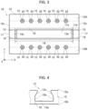
- FIG. 3 is a top view of the jig 10.
- FIG. 4 is a front view of a wedge fitting groove 13 according to the present embodiment.
- the illustration of a base 11 and a root portion 3 shown in FIG. 2 is omitted in in FIG. 3 .
- Common parts in each figure are denoted by the same reference numerals, and duplicate explanations are omitted.
- the X, Y and Z directions orthogonal to each other are defined.
- the X and Y directions are parallel to a X-Y plane (virtual plane) including the vibration direction of the vibration table (not shown).
- the X direction is the extending direction of a slot 16 (see FIG. 3 ).
- the Z direction is orthogonal to the X and Y directions.
- the jig 10 is mounted on a vibration table (not shown) of the vibration test apparatus and holds an end of a test body.
- the end of the test body has a cross-sectional shape that is pressed against the base 11 by the top plate 12.
- the test body is a so-called long piece and has an end that extends in the X direction and a body that extends from the end in a predetermined direction (e.g., Z direction) that crosses the X-Y plane.
- a fan blade 1 used in an aircraft engine such as a turbofan engine (not shown) will be described below as an example of the test body.
- the fan blade 1 as the test body includes a blade body 2 as a main body of the test body and a root portion 3 as an end of the test body.
- the blade body 2 and the root portion 3 are integrally formed.
- the blade body 2 has a leading edge 2a, a trailing edge 2b, a tip 2c, and a hub 2d.
- the blade body 2 extends from the root portion 3 to the tip 2c via the hub 2d in a span direction SD.
- the root portion 3 is connected to the hub 2d of the blade body 2 and extended in one direction to be fit into a groove (dovetail groove) of a rotor (not shown) to which the fan blade 1 is attached.
- the extending direction of the root portion 3 may coincide with the X direction.
- the root portion 3 is mounted on the mounting surface 11a of the base 11 (see FIG. 2 ).
- the root portion 3 has a pair of side surfaces 3a and 3a (see FIG. 2 ) and a bottom surface 3b (see FIG. 2 ).
- the root portion 3 has a cross-sectional shape complementary to the cross-sectional shape of the groove portion (not shown). That is, the root portion 3 includes a width that extends in the Y direction as it moves away from the blade body 2.
- a pair of side surfaces 3a and 3a are slopes defining this width.
- the bottom surface 3b is located between the side surfaces 3a and 3a and connects to each side surface.
- the jig 10 includes a base 11, a top plate 12, and pressing members 14.
- Each pressing member 14 is composed of a bolt 15 formed integrally with a screw part 14a and a head part 14b.
- the pressing member 14 may be composed of a screw part 14a formed as a stud bolt and a nut 14c screwed into the screw part 14a (see FIG. 2 ).
- the bolt 15 will be described as an example of the pressing member 14.
- the base 11 is a flat plate having a predetermined thickness in the Z direction and extending in X and Y directions.
- the base 11 is formed of a metal having high rigidity such as stainless steel.
- the thickness of the base 11 is set to a value to obtain sufficient rigidity against the axial force of the bolt 15 during fastening and the stress during vibration.
- the base 11 is installed on a vibration table (not shown) of the vibration test apparatus and is fixed thereto by a fastening member such as a bolt in a state where the direction of the base 11 is adjusted to obtain a desired vibration direction.
- the base 11 includes a mounting surface 11a on which the root portion 3 is mounted.
- the mounting surface 11a faces the top plate 12.
- the mounting surface 11a is formed as an upper surface of the mounting stage 11b projecting from the base 11 toward the top plate 12.
- the height of the mounting stage 11b according to the present embodiment is set to a value capable of maintaining a gap between the base 11 and the top plate 12 when the top plate 12 presses the root portion 3 against the mounting surface 11a.
- the top plate 12 is a rectangular flat plate having a predetermined thickness in the Z direction and extending in X and Y directions.
- the top plate 12 is placed on the base 11 with a gap therebetween. Similar to the base 11, the top plate 12 is formed of a metal having high rigidity such as stainless steel.
- the thickness of the top plate 12 is set to a value to obtain sufficient rigidity against the axial force of the bolt 15 during fastening and the stress during vibration.
- the shape of the top plate 12 is not limited to a rectangular shape and may be a circular shape or the like.
- the top plate 12 has a slot (holding groove) 16 in which at least a part of the root portion 3 is accommodated.
- the slot 16 extends in the X direction.
- the slot 16 opens on an upper surface 12a of the top plate 12 and also opens on a lower surface 12b of the top plate 12 as an insertion port 18 of the mounting table 11b.
- a part of the root portion 3 including the bottom surface 3b is accommodated in the slot 16.
- a wedge fitting groove 13 (described later) is provided on both sides of the slot 16 in the extending direction (i.e., the X direction).
- the slot 16 has an inner surface 16a for pressing the root portion 3 located in the slot 16 toward the mounting surface 11a. That is, the cross section of the slot 16 orthogonal to the X direction includes an outline corresponding to the side surfaces 3a and 3a of the root portion 3 located in the slot 16. As a result, a part of the inner surface 16a contacts the pair of side surfaces 3a and 3a of the root portion 3.
- the depth of the slot 16 along the Z direction is deeper than the length of a part of the root portion 3 along the Z direction, the part being accommodated in the slot 16. Further, a part of the slot 16 on a lower surface 12b side has a width wider than the width of the root portion 3 along the Y direction. Thus, when the root portion 3 is inserted into the slot 16 through the insertion port 17, a sufficient gap is formed between the root portion 3 and the inner surface 16a of the slot 16, and the root portion 3 can be easily inserted into the slot 16.
- the top plate 12 has the wedge fitting groove 13 extending in the X direction. As described above, the wedge fitting groove 13 is located on both sides in the extending direction of the slot 16 with respect to the slot 16. The wedge fitting groove 13 is arranged in a line in the X direction together with the slot 16 and communicates with the slot 16. The wedge fitting groove 13 is opened to the top surface 12a of the top plate 12 and the side surface 12c of the top plate 12.
- the cross-sectional shape of the wedge fitting groove 13 is included in the cross-sectional shape of the slot 16, when viewed from the X direction. In other words, the cross-sectional shape of the wedge fitting groove 13 coincides with a part of the cross-sectional shape of the slot 16, when viewed from the X direction. Therefore, the wedge fitting groove 13 functions as an insertion port 17 of the root portion 3.
- An inner surface of the wedge fitting groove 13 includes at least a bottom surface 13a and a pair of holding surfaces 13s and 13s.
- the bottom surface 13a is a plane parallel to the X-Y plane and also serves as a top surface of the link portion 19 between a plate portion 12A on one side sandwiching the slot 16 and a plate portion 12B on the other side.
- the pair of holding surfaces 13s and 13s are formed, for example, on at least a part of the pair of side surfaces 13b and 13b.
- the pair of holding surfaces 13s and 13s are located on both sides of the wedge fitting groove 13 in the width direction (Y direction) and face the bottom surface 13a across an inner space of the wedge fitting groove 13.
- the pair of holding surfaces 13s and 13s are inclined to the bottom surface 13a.
- the bolts 15 are arranged in the X direction on the top plate 12 and are screwed to screw holes 20 provided on the base 11 through the top plate 12.
- the top plate 12 moves toward the base 11. Therefore, when the bolt 15 is tightened while the root portion 3 has been inserted into the slot 16 and placed on the mounting stage 11b, the top plate 12 gradually descends, and the inner surface 16a of the slot 16 contacts the side surfaces 3a and 3a of the root portion 3. On the other hand, the root portion 3 cannot descend because it is placed on the mounting stage 11b.
- the inner surface 16a of the slot 16 presses the side surfaces 3a and 3a of the root portion 3, and the root portion 3 is pressed against the mounting surface 11a of the mounting stage 11b.
- the fan blade 1 is held by the jig 10.
- a strain sensor 22 is embedded in each bolt 15.
- the strain sensor 22 measures the axial force generated in the bolt 15.
- a constant axial force can be set for each bolt 15 by confirming the axial force measured by the strain sensor 22. Therefore, a uniform load can be applied to the root portion 3 and the jig 10.
- the load applied to the jig 10 varies periodically in accordance with the vibration of the fan blade 1.
- the load on the root portion 3 decreases.
- the root portion 3 may move in the slot 16. Therefore, the jig 10 according to the present embodiment includes a wedge portion 23 that fits into the wedge fitting groove 13.
- the wedge portion 23 makes surface contacts with the bottom surface 13a, which is the inner surface of the wedge fitting groove 13, and the pair of holding surfaces 13s and 13s.
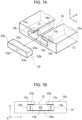
- FIG. 6A is a perspective view showing a state before the wedge portion 23 is fitted into the wedge fitting groove 13 of the top plate 12
- FIG. 6B is a front view showing a state after the wedge portion 23 is fitted into the wedge fitting groove 13 of the top plate 12.
- the wedge portion 23 is a block made of metal.
- the wedge portion 23 is formed of the same metal material as the top plate 12 or a metal material having higher rigidity than that of the top plate 12.
- Such a material may be, for example, stainless steel or chromium molybdenum steel (SCM).
- the wedge portion 23 has a bottom surface 23a, a pair of side surfaces 23b and 23b, a top surface 23c, a front surface 23d, and a rear surface 23e.
- the bottom surface 23a, a pair of side surfaces 23b and 23b, and a top surface 23c define the cross-sectional shape of the wedge portion 23 that fits into the wedge fitting groove 13.
- the defined cross-sectional shape coincides with, for example, the cross-sectional shape of the wedge fitting groove 13.
- the pair of side surfaces 23b and 23b includes a pair of inclined surfaces 23s and 23s.
- the pair of inclined surfaces 23s and 23s are inclined to the bottom surface 23a at the same angle as the pair of holding surfaces 13s and 13s while facing the bottom surface 23a.
- the relative movement between the wedge portion 23 and the wedge fitting groove 13 along the contact surface is regulated.
- the holding surface 13s of the wedge fitting groove 13 is in surface contact with the inclined surface 23s, and the bottom surface 23a of the wedge portion 23 is in surface contact with the bottom surface 13a of the wedge fitting groove 13. Therefore, even if the bottom surface 13a of the wedge fitting groove 13 (i.e., the link portion 19 of the top plate 12) would be warped bent in the Y-Z plane, the movement of the wedge portion 23 in the Z direction is restricted. Accordingly, the warpage of the bottom surface 13a (the link portion 19 of the top plate 12) is restricted.
- the deformation of the top plate 12 to expand the opening of the slot 16, which opens toward the Z direction, is suppressed, and the excessive reduction of the load on the root portion 3 in the slot 16 is suppressed. Therefore, the fan blade 1 can be stably held even during the vibration of the fan blade 1.
- FIG. 7A is a perspective view showing a state before the wedge portion 23 of the modified example is fitted into the wedge fitting groove 13 of the modified example.
- FIG. 7B is a front view showing a state after the wedge portion 23 is fitted into the wedge fitting groove 13.
- the pair of holding surfaces 13s and 13s in the wedge fitting groove 13 may be parallel to the bottom surface 13a.
- the wedge fitting groove 13 includes a rectangular cross section whose long sides are defined by the pair of holding surfaces 13s and 13s and the bottom surface 13a.
- the wedge portion 23 has a cross section complementary to this rectangular cross section and fits into the wedge fitting groove 13.
- the top surface 23c of the wedge portion 23 makes surface contact with the pair of holding surfaces 13s and 13s of the wedge fitting groove 13
- the bottom surface 23a of the wedge portion 23 makes surface contact with the bottom surface 13a of the wedge fitting groove 13. That is, in this example as well, since the wedge portion 23 makes surface contact with the pair of holding surfaces 13s and 13s and the bottom surface 13a of the wedge fitting groove 13, the warpage of the bottom surface 13a (the link portion 19 of the top plate 12) of the wedge fitting groove 13 is restricted. Accordingly, the fan blade 1 can be stably held even during the vibration of the fan blade 1.
- the root portion 3 of the fan blade 1 is inserted into the insertion port 17 and further moved to the slot 16, and the root portion 3 is positioned on the mounting surface 11a.
- the wedge portion 23 is inserted into the wedge fitting groove 13.
- all bolts 15 are gradually tightened until desired axial forces are obtained while changing the bolt 15 to be tightened.
- one-sided tightening in order to avoid that only a group of some bolts 15 that are close to each other are extremely tightened (so-called one-sided tightening), after one of the bolts 15 is tightened, the other of the bolts 15, which is sufficiently separated from the one bolt 15 already tightened, is tightened.
- the bottom surface 3b of the root portion 3 comes into contact with the mounting surface 11a, and the root portion 3 is pressed toward the mounting surface 11a by the inner surface 16a of the slot 16, thereby restricting the movement of the root portion 3. That is, the fan blade 1 is held by the jig 10. Further, the jig 10 stably holds the fan blade 1 even during vibration by fitting the wedge portion 23 to the wedge fitting groove 13.
Landscapes
- Physics & Mathematics (AREA)
- General Physics & Mathematics (AREA)
- Engineering & Computer Science (AREA)
- Analytical Chemistry (AREA)
- General Health & Medical Sciences (AREA)
- Health & Medical Sciences (AREA)
- Life Sciences & Earth Sciences (AREA)
- Chemical & Material Sciences (AREA)
- Transportation (AREA)
- Biochemistry (AREA)
- Aviation & Aerospace Engineering (AREA)
- Manufacturing & Machinery (AREA)
- Immunology (AREA)
- Pathology (AREA)
- Structures Of Non-Positive Displacement Pumps (AREA)
- Turbine Rotor Nozzle Sealing (AREA)
- Investigating Strength Of Materials By Application Of Mechanical Stress (AREA)
Abstract

Description
- The present disclosure relates to a vibration test jig that holds an end of a test body extending in a predetermined direction, such as a fan blade used in aircraft engines.
- A vibration test is one of the tests for evaluating the fatigue properties of a test body. In the vibration test, a test body is vibrated to be applied with constant stress. Generally, fatigue when the number of times leading to damage such as rupture (i.e., the number of cycles to rupture) is less than a predetermined value (e.g., 104 times) is called low-cycle fatigue, and fatigue when this number exceeds the predetermined value (e.g., 104 times) is called high-cycle fatigue. To assess the correlation between stress and the number of cycles to rupture, it is necessary to vibrate the test body for a long period of time, and the test duration often ranges from several days to several weeks.
- Patent Literature 1 (PLT 1) discloses a vibration test jig for a rotor blade, which is attached to a vibration table of a vibration test apparatus. The jig of
Patent Literature 1 includes a top plate and a jig body as a base fixed to a vibration table. The rotor blade is placed on a mounting base of the jig body with a root portion thereof positioned in a holding groove of the top plate. In addition, bolts are screwed into the jig body through the top plate. By tightening these bolts, the top plate moves toward the jig body, and as a result, the root portion is pressed against the mounting base. As a result, the root portion is held by the jig, and the vibration test can be performed. - Patent Literature 1:
WO 2020/208925 A1 - In the vibration test jig according to
PLT 1, the rotor blade is held by a load which is applied to the root portion of the rotor blade from the top plate toward the base. This load value is set depending on to the operating environment of the test body. For example, since the test body ofPatent Literature 1 is a rotor blade, a very large load (e.g., 20 t) equivalent to centrifugal force is applied to the root portion of the rotor blade. - While vibrating the test body in a state where an end of the test body is held by the jig, a load applied to the end fluctuates in accordance with the vibration of the test body. Although the end of the test body is stably held by the jig during the test body is at rest, the load is reduced by deformation of the jig during the test body is vibrated, thereby the test body may move in the jig.
- The present disclosure has been made in view of the above-mentioned circumstances, and an object of the present disclosure is to provide a vibration test jig capable of stably holding the test body even during vibration of the test body.
- A vibration test jig according to one aspect of the present disclosure is a jig for holding an end of a test body extending in a predetermined direction. The jig includes: a base installed on a vibration table, including a mounting surface on which the end of the test body is mounted; a top plate placed on the base with a gap therebetween, including a slot and a wedge fitting groove, the slot having an inner surface that presses the end of the test body toward the mounting surface, and the wedge fitting groove located in an extending direction of the slot and communicating with the slot; a wedge portion configured to be fit into the wedge fitting groove; and pressing members arranged along the slot and configured to press the top plate toward the base; wherein an inner surface of the wedge fitting groove includes a bottom surface and a pair of holding surfaces located on both sides in a width direction of the wedge fitting groove and facing the bottom surface across an inner space of the wedge fitting groove; and the wedge portion is in surface contact with the bottom surface and the pair of holding surfaces.
- A cross-sectional shape of the wedge fitting groove may be included in a cross-sectional shape of the slot, when viewed from an extending direction of the slot. The pair of holding surfaces may be inclined with respect to the bottom surface. The pair of holding surfaces may be parallel to the bottom surface.
- According to the present disclosure, it is possible to provide a vibration test jig capable of stably holding the test body even during vibration of the test body.
-
-
FIG. 1 is a perspective view of a fan blade as an example of a test body held in a jig according to the embodiment of the present disclosure. -
FIG. 2 is a front view of the jig according to the embodiment of the present disclosure. -
FIG. 3 is a top view of the jig according to the embodiment of the present disclosure. -
FIG. 4 is a front view of a wedge fitting groove according to the present embodiment. -
FIG. 5 is a front view of a top plate assuming a bent state. -
FIG. 6A is a perspective view showing a state before the wedge portion according to the present embodiment is fitted into the wedge fitting groove of the top plate. -
FIG. 6B is a front view showing a state after the wedge portion according to the present embodiment is fitted into the wedge fitting groove of the top plate. -
FIG. 7A is a perspective view showing a state before the wedge portion according to a modification of the present embodiment is fitted into the wedge fitting groove of the top plate. -
FIG. 7B is a front view showing a state after the wedge portion according to the modification of the present embodiment is fitted into the wedge fitting groove of the top plate. - Hereinafter, a
jig 10 according to an embodiment of the present disclosure will be described with reference to the drawings.FIG. 1 is a perspective view of afan blade 1 which is an example of a test body will be held in thejig 10.FIG. 2 is a front view of thejig 10 according to the present embodiment.FIG. 3 is a top view of thejig 10.FIG. 4 is a front view of awedge fitting groove 13 according to the present embodiment. For convenience of explanation, the illustration of abase 11 and aroot portion 3 shown inFIG. 2 is omitted in inFIG. 3 . Common parts in each figure are denoted by the same reference numerals, and duplicate explanations are omitted. - For convenience of explanation, the X, Y and Z directions orthogonal to each other are defined. The X and Y directions are parallel to a X-Y plane (virtual plane) including the vibration direction of the vibration table (not shown). The X direction is the extending direction of a slot 16 (see
FIG. 3 ). The Z direction is orthogonal to the X and Y directions. - The
jig 10 according to the present embodiment is mounted on a vibration table (not shown) of the vibration test apparatus and holds an end of a test body. The end of the test body has a cross-sectional shape that is pressed against thebase 11 by thetop plate 12. The test body is a so-called long piece and has an end that extends in the X direction and a body that extends from the end in a predetermined direction (e.g., Z direction) that crosses the X-Y plane. Afan blade 1 used in an aircraft engine such as a turbofan engine (not shown) will be described below as an example of the test body. - As shown in
FIG. 1 , thefan blade 1 as the test body includes ablade body 2 as a main body of the test body and aroot portion 3 as an end of the test body. Theblade body 2 and theroot portion 3 are integrally formed. Theblade body 2 has a leadingedge 2a, atrailing edge 2b, atip 2c, and ahub 2d. Theblade body 2 extends from theroot portion 3 to thetip 2c via thehub 2d in a span direction SD. - The
root portion 3 is connected to thehub 2d of theblade body 2 and extended in one direction to be fit into a groove (dovetail groove) of a rotor (not shown) to which thefan blade 1 is attached. The extending direction of theroot portion 3 may coincide with the X direction. - The
root portion 3 is mounted on the mountingsurface 11a of the base 11 (seeFIG. 2 ). Theroot portion 3 has a pair ofside surfaces FIG. 2 ) and abottom surface 3b (seeFIG. 2 ). Theroot portion 3 has a cross-sectional shape complementary to the cross-sectional shape of the groove portion (not shown). That is, theroot portion 3 includes a width that extends in the Y direction as it moves away from theblade body 2. A pair ofside surfaces bottom surface 3b is located between the side surfaces 3a and 3a and connects to each side surface. When theroot portion 3 is mounted on the mountingsurface 11a of thebase 11, thebottom surface 3b contacts the mountingsurface 11a. - As shown in
FIGs. 2 and3 , thejig 10 includes abase 11, atop plate 12, and pressingmembers 14. Each pressingmember 14 is composed of abolt 15 formed integrally with ascrew part 14a and ahead part 14b. Alternatively, the pressingmember 14 may be composed of ascrew part 14a formed as a stud bolt and anut 14c screwed into thescrew part 14a (seeFIG. 2 ). By tightening thebolt 15 in the former case and thenut 14c in the latter case, thetop plate 12 is pressed toward thebase 11. Hereinafter, for convenience of explanation, thebolt 15 will be described as an example of the pressingmember 14. - The
base 11 is a flat plate having a predetermined thickness in the Z direction and extending in X and Y directions. Thebase 11 is formed of a metal having high rigidity such as stainless steel. The thickness of thebase 11 is set to a value to obtain sufficient rigidity against the axial force of thebolt 15 during fastening and the stress during vibration. Thebase 11 is installed on a vibration table (not shown) of the vibration test apparatus and is fixed thereto by a fastening member such as a bolt in a state where the direction of thebase 11 is adjusted to obtain a desired vibration direction. - The
base 11 includes a mountingsurface 11a on which theroot portion 3 is mounted. The mountingsurface 11a faces thetop plate 12. For example, the mountingsurface 11a is formed as an upper surface of the mountingstage 11b projecting from the base 11 toward thetop plate 12. The height of the mountingstage 11b according to the present embodiment is set to a value capable of maintaining a gap between the base 11 and thetop plate 12 when thetop plate 12 presses theroot portion 3 against the mountingsurface 11a. - The
top plate 12 is a rectangular flat plate having a predetermined thickness in the Z direction and extending in X and Y directions. Thetop plate 12 is placed on the base 11 with a gap therebetween. Similar to thebase 11, thetop plate 12 is formed of a metal having high rigidity such as stainless steel. The thickness of thetop plate 12 is set to a value to obtain sufficient rigidity against the axial force of thebolt 15 during fastening and the stress during vibration. The shape of thetop plate 12 is not limited to a rectangular shape and may be a circular shape or the like. - The
top plate 12 has a slot (holding groove) 16 in which at least a part of theroot portion 3 is accommodated. Theslot 16 extends in the X direction. Theslot 16 opens on anupper surface 12a of thetop plate 12 and also opens on alower surface 12b of thetop plate 12 as aninsertion port 18 of the mounting table 11b. A part of theroot portion 3 including thebottom surface 3b is accommodated in theslot 16. A wedge fitting groove 13 (described later) is provided on both sides of theslot 16 in the extending direction (i.e., the X direction). - The
slot 16 has aninner surface 16a for pressing theroot portion 3 located in theslot 16 toward the mountingsurface 11a. That is, the cross section of theslot 16 orthogonal to the X direction includes an outline corresponding to the side surfaces 3a and 3a of theroot portion 3 located in theslot 16. As a result, a part of theinner surface 16a contacts the pair ofside surfaces root portion 3. - The depth of the
slot 16 along the Z direction is deeper than the length of a part of theroot portion 3 along the Z direction, the part being accommodated in theslot 16. Further, a part of theslot 16 on alower surface 12b side has a width wider than the width of theroot portion 3 along the Y direction. Thus, when theroot portion 3 is inserted into theslot 16 through theinsertion port 17, a sufficient gap is formed between theroot portion 3 and theinner surface 16a of theslot 16, and theroot portion 3 can be easily inserted into theslot 16. - The
top plate 12 has thewedge fitting groove 13 extending in the X direction. As described above, thewedge fitting groove 13 is located on both sides in the extending direction of theslot 16 with respect to theslot 16. The wedgefitting groove 13 is arranged in a line in the X direction together with theslot 16 and communicates with theslot 16. The wedgefitting groove 13 is opened to thetop surface 12a of thetop plate 12 and theside surface 12c of thetop plate 12. The cross-sectional shape of thewedge fitting groove 13 is included in the cross-sectional shape of theslot 16, when viewed from the X direction. In other words, the cross-sectional shape of thewedge fitting groove 13 coincides with a part of the cross-sectional shape of theslot 16, when viewed from the X direction. Therefore, thewedge fitting groove 13 functions as aninsertion port 17 of theroot portion 3. - An inner surface of the
wedge fitting groove 13 includes at least abottom surface 13a and a pair of holdingsurfaces bottom surface 13a is a plane parallel to the X-Y plane and also serves as a top surface of thelink portion 19 between aplate portion 12A on one side sandwiching theslot 16 and aplate portion 12B on the other side. The pair of holdingsurfaces surfaces wedge fitting groove 13 in the width direction (Y direction) and face thebottom surface 13a across an inner space of thewedge fitting groove 13. The pair of holdingsurfaces bottom surface 13a. - The
bolts 15 are arranged in the X direction on thetop plate 12 and are screwed to screwholes 20 provided on the base 11 through thetop plate 12. When eachbolt 15 is tightened, thetop plate 12 moves toward thebase 11. Therefore, when thebolt 15 is tightened while theroot portion 3 has been inserted into theslot 16 and placed on the mountingstage 11b, thetop plate 12 gradually descends, and theinner surface 16a of theslot 16 contacts the side surfaces 3a and 3a of theroot portion 3. On the other hand, theroot portion 3 cannot descend because it is placed on the mountingstage 11b. Therefore, when thebolt 15 is tightened further, theinner surface 16a of theslot 16 presses the side surfaces 3a and 3a of theroot portion 3, and theroot portion 3 is pressed against the mountingsurface 11a of the mountingstage 11b. Thus, thefan blade 1 is held by thejig 10. - A
strain sensor 22 is embedded in eachbolt 15. Thestrain sensor 22 measures the axial force generated in thebolt 15. When thebolt 15 is tightened, a constant axial force can be set for eachbolt 15 by confirming the axial force measured by thestrain sensor 22. Therefore, a uniform load can be applied to theroot portion 3 and thejig 10. - However, the load applied to the
jig 10 varies periodically in accordance with the vibration of thefan blade 1. When this variation is excessively large, deformation of thetop plate 12 leading to open theslot 16 occurs (seeFIG. 5 ), and the load on theroot portion 3 decreases. When the load on theroot portion 3 is excessively reduced, theroot portion 3 may move in theslot 16. Therefore, thejig 10 according to the present embodiment includes awedge portion 23 that fits into thewedge fitting groove 13. Thewedge portion 23 makes surface contacts with thebottom surface 13a, which is the inner surface of thewedge fitting groove 13, and the pair of holdingsurfaces -
FIG. 6A is a perspective view showing a state before thewedge portion 23 is fitted into thewedge fitting groove 13 of thetop plate 12, andFIG. 6B is a front view showing a state after thewedge portion 23 is fitted into thewedge fitting groove 13 of thetop plate 12. As shown inFIG. 6A , thewedge portion 23 is a block made of metal. Thewedge portion 23 is formed of the same metal material as thetop plate 12 or a metal material having higher rigidity than that of thetop plate 12. Such a material may be, for example, stainless steel or chromium molybdenum steel (SCM). - The
wedge portion 23 has abottom surface 23a, a pair of side surfaces 23b and 23b, atop surface 23c, afront surface 23d, and arear surface 23e. Thebottom surface 23a, a pair of side surfaces 23b and 23b, and atop surface 23c define the cross-sectional shape of thewedge portion 23 that fits into thewedge fitting groove 13. The defined cross-sectional shape coincides with, for example, the cross-sectional shape of thewedge fitting groove 13. The pair of side surfaces 23b and 23b includes a pair ofinclined surfaces inclined surfaces bottom surface 23a at the same angle as the pair of holdingsurfaces bottom surface 23a. - As shown in
FIG. 6B , when thewedge portion 23 is fitted into thewedge fitting groove 13, thebottom surface 23a of thewedge portion 23 comes into surface contact with thebottom surface 13a of thewedge fitting groove 13. Further, theinclined surface 23s which is a part of theside surface 23b of thewedge portion 23 comes into surface contact with the holdingsurface 13s of thewedge fitting groove 13. The arrow inFIG. 5 indicates a load for warping thetop plate 12 in the Z direction with respect to the X-Y plane. When this load is applied to thetop plate 12, an increase in a local pressure occurs at the periphery of the contact surface between theinclined surface 23s of thewedge portion 23 and the holdingsurface 13s of thewedge fitting groove 13. By an increase in the friction force there, the relative movement between thewedge portion 23 and thewedge fitting groove 13 along the contact surface is regulated. The holdingsurface 13s of thewedge fitting groove 13 is in surface contact with theinclined surface 23s, and thebottom surface 23a of thewedge portion 23 is in surface contact with thebottom surface 13a of thewedge fitting groove 13. Therefore, even if thebottom surface 13a of the wedge fitting groove 13 (i.e., thelink portion 19 of the top plate 12) would be warped bent in the Y-Z plane, the movement of thewedge portion 23 in the Z direction is restricted. Accordingly, the warpage of thebottom surface 13a (thelink portion 19 of the top plate 12) is restricted. That is, the deformation of thetop plate 12 to expand the opening of theslot 16, which opens toward the Z direction, is suppressed, and the excessive reduction of the load on theroot portion 3 in theslot 16 is suppressed. Therefore, thefan blade 1 can be stably held even during the vibration of thefan blade 1. -
FIG. 7A is a perspective view showing a state before thewedge portion 23 of the modified example is fitted into thewedge fitting groove 13 of the modified example.FIG. 7B is a front view showing a state after thewedge portion 23 is fitted into thewedge fitting groove 13. As shown in these views, the pair of holdingsurfaces wedge fitting groove 13 may be parallel to thebottom surface 13a. For example, thewedge fitting groove 13 includes a rectangular cross section whose long sides are defined by the pair of holdingsurfaces bottom surface 13a. Thewedge portion 23 has a cross section complementary to this rectangular cross section and fits into thewedge fitting groove 13. In this case, thetop surface 23c of thewedge portion 23 makes surface contact with the pair of holdingsurfaces wedge fitting groove 13, and thebottom surface 23a of thewedge portion 23 makes surface contact with thebottom surface 13a of thewedge fitting groove 13. That is, in this example as well, since thewedge portion 23 makes surface contact with the pair of holdingsurfaces bottom surface 13a of thewedge fitting groove 13, the warpage of thebottom surface 13a (thelink portion 19 of the top plate 12) of thewedge fitting groove 13 is restricted. Accordingly, thefan blade 1 can be stably held even during the vibration of thefan blade 1. - When performing the vibration test, firstly, the
root portion 3 of thefan blade 1 is inserted into theinsertion port 17 and further moved to theslot 16, and theroot portion 3 is positioned on the mountingsurface 11a. Next, thewedge portion 23 is inserted into thewedge fitting groove 13. Thereby, theroot portion 3 is restricted from being detached from theslot 16. Further, allbolts 15 are gradually tightened until desired axial forces are obtained while changing thebolt 15 to be tightened. At this time, in order to avoid that only a group of somebolts 15 that are close to each other are extremely tightened (so-called one-sided tightening), after one of thebolts 15 is tightened, the other of thebolts 15, which is sufficiently separated from the onebolt 15 already tightened, is tightened. As a result, thebottom surface 3b of theroot portion 3 comes into contact with the mountingsurface 11a, and theroot portion 3 is pressed toward the mountingsurface 11a by theinner surface 16a of theslot 16, thereby restricting the movement of theroot portion 3. That is, thefan blade 1 is held by thejig 10. Further, thejig 10 stably holds thefan blade 1 even during vibration by fitting thewedge portion 23 to thewedge fitting groove 13. - It should be noted that the present disclosure is not limited to the foregoing embodiments, but is illustrated by the description of the claims, and further includes all changes within the meaning and scope of the description and equality of the claims.
Claims (4)
- A vibration test jig for holding an end of a test body extending in a predetermined direction, comprising:a base installed on a vibration table, including a mounting surface on which the end of the test body is mounted;a top plate placed on the base with a gap therebetween, including a slot and a wedge fitting groove, the slot having an inner surface that presses the end of the test body toward the mounting surface, and the wedge fitting groove located in an extending direction of the slot and communicating with the slot;a wedge portion configured to be fit into the wedge fitting groove; andpressing members arranged along the slot and configured to press the top plate toward the base; whereinan inner surface of the wedge fitting groove includes a bottom surface and a pair of holding surfaces located on both sides in a width direction of the wedge fitting groove and facing the bottom surface across an inner space of the wedge fitting groove; andthe wedge portion is in surface contact with the bottom surface and the pair of holding surfaces.
- The vibration test jig according to claim 1, wherein
a cross-sectional shape of the wedge fitting groove is included in a cross-sectional shape of the slot, when viewed from an extending direction of the slot. - The vibration test jig according to claim 1, wherein
the pair of holding surfaces is inclined with respect to the bottom surface. - The vibration test jig according to claim 1, wherein
the pair of holding surfaces is parallel to the bottom surface.
Applications Claiming Priority (2)
| Application Number | Priority Date | Filing Date | Title |
|---|---|---|---|
| JP2022007733 | 2022-01-21 | ||
| PCT/JP2022/034888 WO2023139842A1 (en) | 2022-01-21 | 2022-09-20 | Vibration testing jig |
Publications (2)
| Publication Number | Publication Date |
|---|---|
| EP4467956A1 true EP4467956A1 (en) | 2024-11-27 |
| EP4467956A4 EP4467956A4 (en) | 2025-12-31 |
Family
ID=87348587
Family Applications (1)
| Application Number | Title | Priority Date | Filing Date |
|---|---|---|---|
| EP22921995.1A Pending EP4467956A4 (en) | 2022-01-21 | 2022-09-20 | VIBRATION TEST DEVICE |
Country Status (5)
| Country | Link |
|---|---|
| US (1) | US20240361205A1 (en) |
| EP (1) | EP4467956A4 (en) |
| JP (1) | JP7666656B2 (en) |
| CA (1) | CA3247977A1 (en) |
| WO (1) | WO2023139842A1 (en) |
Family Cites Families (7)
| Publication number | Priority date | Publication date | Assignee | Title |
|---|---|---|---|---|
| GB201001284D0 (en) | 2010-01-27 | 2010-03-10 | Rolls Royce Plc | Apparatus for generating vibrations in a component |
| JP5725849B2 (en) | 2010-12-27 | 2015-05-27 | 三菱日立パワーシステムズ株式会社 | fixing jig |
| JP6165021B2 (en) | 2013-10-29 | 2017-07-19 | 三菱重工業株式会社 | Fixed blade |
| CN207408062U (en) | 2017-09-29 | 2018-05-25 | 苏州泰斯特测控科技有限公司 | Swallow-tail form tenon blade fatigue test device |
| FR3084161B1 (en) | 2018-07-23 | 2020-10-16 | Safran Aircraft Engines | TEST ASSEMBLY, AND VIBRATORY FATIGUE TEST MACHINE. |
| CN109029889B (en) | 2018-08-27 | 2023-09-26 | 烟台大学 | Vibration test device and method for aero-engine blade |
| JP7093063B2 (en) | 2019-04-12 | 2022-06-29 | 株式会社Ihi | Vibration test jig for rotor blades |
-
2022
- 2022-09-20 EP EP22921995.1A patent/EP4467956A4/en active Pending
- 2022-09-20 JP JP2023575057A patent/JP7666656B2/en active Active
- 2022-09-20 WO PCT/JP2022/034888 patent/WO2023139842A1/en not_active Ceased
- 2022-09-20 CA CA3247977A patent/CA3247977A1/en active Pending
-
2024
- 2024-07-11 US US18/769,496 patent/US20240361205A1/en active Pending
Also Published As
| Publication number | Publication date |
|---|---|
| WO2023139842A1 (en) | 2023-07-27 |
| JP7666656B2 (en) | 2025-04-22 |
| JPWO2023139842A1 (en) | 2023-07-27 |
| US20240361205A1 (en) | 2024-10-31 |
| EP4467956A4 (en) | 2025-12-31 |
| CA3247977A1 (en) | 2025-02-25 |
Similar Documents
| Publication | Publication Date | Title |
|---|---|---|
| EP2351631B1 (en) | Apparatus for generating vibrations in a component | |
| EP2740950B1 (en) | Radial foil bearing | |
| US20090116964A1 (en) | Turbine rotor and method for producing the rotor | |
| EP3002471A1 (en) | Radial foil bearing | |
| CN111069941B (en) | A fixture system and processing method for high-speed precision broaching machining turbine disk tongue and groove | |
| EP2159372A2 (en) | Fixture for compressor stator chord restoration repair | |
| JP6246893B2 (en) | Rotor blade holding device, rotor blade fixing member pushing device, rotating machine manufacturing method, assembling method, dismantling method | |
| EP2799735A2 (en) | Protection clip for torque receiving part | |
| JP2011528415A (en) | Method of repairing or reworking a turbomachine disc, and repaired or reworked turbomachine disc | |
| US8512001B2 (en) | Turbomachine rotor comprising a pretensioning device for pretensioning a rotor blade | |
| US20240344923A1 (en) | Vibration test jig | |
| US20240361205A1 (en) | Vibration test jig | |
| CN110631789B (en) | Test method for vibration fatigue testing of composite stator blades | |
| US4884951A (en) | Method of clamping blades | |
| CN105422696B (en) | Non-excitation actuating brake | |
| JP2003270081A (en) | Turbine blade support structure | |
| JP2001337016A (en) | Dovetail fixing structure of tensile tester | |
| US20180154423A1 (en) | Press die | |
| US20190338655A1 (en) | Method for optimizing a natural frequency of a rotor blade, and rotor blade | |
| CN214538976U (en) | Blade tenon tensile test anchor clamps, rotor blade test piece and tensile test structure | |
| CN115540717A (en) | Stud bolt length measuring tool and stud bolt length measuring method | |
| US6151929A (en) | Device for fastening active components to the bar of a wrap knitting machine and accompanying tool for removing and installing the active components | |
| CN214774348U (en) | Cardboard processing structure of a creasing machine and creasing machine | |
| CN111496900B (en) | A flexible clamping device and method for providing uniform distribution force, and a vibration cutting device | |
| CN107461412A (en) | Support arrangement structure |
Legal Events
| Date | Code | Title | Description |
|---|---|---|---|
| STAA | Information on the status of an ep patent application or granted ep patent |
Free format text: STATUS: THE INTERNATIONAL PUBLICATION HAS BEEN MADE |
|
| PUAI | Public reference made under article 153(3) epc to a published international application that has entered the european phase |
Free format text: ORIGINAL CODE: 0009012 |
|
| STAA | Information on the status of an ep patent application or granted ep patent |
Free format text: STATUS: REQUEST FOR EXAMINATION WAS MADE |
|
| 17P | Request for examination filed |
Effective date: 20240812 |
|
| AK | Designated contracting states |
Kind code of ref document: A1 Designated state(s): AL AT BE BG CH CY CZ DE DK EE ES FI FR GB GR HR HU IE IS IT LI LT LU LV MC MK MT NL NO PL PT RO RS SE SI SK SM TR |
|
| DAV | Request for validation of the european patent (deleted) | ||
| DAX | Request for extension of the european patent (deleted) | ||
| A4 | Supplementary search report drawn up and despatched |
Effective date: 20251203 |
|
| RIC1 | Information provided on ipc code assigned before grant |
Ipc: G01M 7/02 20060101AFI20251127BHEP Ipc: G01N 3/32 20060101ALI20251127BHEP Ipc: F03D 17/00 20160101ALI20251127BHEP Ipc: B64F 5/60 20170101ALI20251127BHEP |