EP4467947A1 - Pressure sensitive sensor unit - Google Patents
Pressure sensitive sensor unit Download PDFInfo
- Publication number
- EP4467947A1 EP4467947A1 EP22920559.6A EP22920559A EP4467947A1 EP 4467947 A1 EP4467947 A1 EP 4467947A1 EP 22920559 A EP22920559 A EP 22920559A EP 4467947 A1 EP4467947 A1 EP 4467947A1
- Authority
- EP
- European Patent Office
- Prior art keywords
- pressure sensitive
- sensitive sensor
- load
- base material
- electrode
- Prior art date
- Legal status (The legal status is an assumption and is not a legal conclusion. Google has not performed a legal analysis and makes no representation as to the accuracy of the status listed.)
- Pending
Links
Images





Classifications
-
- G—PHYSICS
- G01—MEASURING; TESTING
- G01L—MEASURING FORCE, STRESS, TORQUE, WORK, MECHANICAL POWER, MECHANICAL EFFICIENCY, OR FLUID PRESSURE
- G01L1/00—Measuring force or stress, in general
- G01L1/20—Measuring force or stress, in general by measuring variations in ohmic resistance of solid materials or of electrically-conductive fluids; by making use of electrokinetic cells, i.e. liquid-containing cells wherein an electrical potential is produced or varied upon the application of stress
- G01L1/22—Measuring force or stress, in general by measuring variations in ohmic resistance of solid materials or of electrically-conductive fluids; by making use of electrokinetic cells, i.e. liquid-containing cells wherein an electrical potential is produced or varied upon the application of stress using resistance strain gauges
- G01L1/2287—Measuring force or stress, in general by measuring variations in ohmic resistance of solid materials or of electrically-conductive fluids; by making use of electrokinetic cells, i.e. liquid-containing cells wherein an electrical potential is produced or varied upon the application of stress using resistance strain gauges constructional details of the strain gauges
-
- G—PHYSICS
- G01—MEASURING; TESTING
- G01L—MEASURING FORCE, STRESS, TORQUE, WORK, MECHANICAL POWER, MECHANICAL EFFICIENCY, OR FLUID PRESSURE
- G01L1/00—Measuring force or stress, in general
- G01L1/20—Measuring force or stress, in general by measuring variations in ohmic resistance of solid materials or of electrically-conductive fluids; by making use of electrokinetic cells, i.e. liquid-containing cells wherein an electrical potential is produced or varied upon the application of stress
- G01L1/22—Measuring force or stress, in general by measuring variations in ohmic resistance of solid materials or of electrically-conductive fluids; by making use of electrokinetic cells, i.e. liquid-containing cells wherein an electrical potential is produced or varied upon the application of stress using resistance strain gauges
Definitions
- the present invention relates to a pressure sensitive sensor unit including a pressure sensitive sensor that detects the magnitude of an applied load.
- a known pressure sensitive sensor includes an upper circuit board having a pair of interdigitated comb-shaped electrodes and a lower circuit board having a disk-shaped electrode facing the comb-shaped electrodes.
- this pressure sensitive sensor at least one of the three electrodes described above is a pressure sensitive resistive body (see, for example, Patent Document 1 (paragraphs [0002] to [0005] and Figs. 1(a) to 1(c))).
- another known pressure sensitive sensor includes an upper circuit board having a disk-shaped pressure sensitive resistive body and a lower circuit board having a disk-shaped counter electrode facing the pressure sensitive resistive body (see, for example, Patent Document 1 (paragraphs [0006] to [0008] and Figs. 2(a) to 2(c))).
- Patent Document 1 JP 2002-158103 A
- a problem to be solved by the invention is to provide a pressure sensitive sensor unit capable of detecting a wide range of loads.
- the pressure sensitive sensor unit according to the invention includes the first load transmitting member that transmits a load belonging to the first load range to the first pressure sensitive sensor and the second load transmitting member that transmits a load belonging to the second load range larger than the first load range to the second pressure sensitive sensor. Therefore, since the pressure sensitive sensor unit according to the invention can detect a load in both the first range and the second range, it is possible to increase the detectable load range.
- Fig. 1 is a plan view showing an example of a pressure sensitive sensor unit according to an embodiment of the invention.
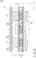
- Fig. 2 is a cross-sectional view taken along the line II-II of Fig. 1 .
- Fig. 2 shows a pressure sensitive sensor unit in an unloaded state in which no load is applied.
- a pressure sensitive sensor unit 1A is a pressure sensitive sensor unit whose output changes according to the magnitude of the applied load.
- a resistance value is used as this output.
- this output is not limited to the resistance value, but may be, for example, a voltage value.
- the pressure sensitive sensor unit 1A includes a pressure sensitive sensor sheet 2, a plurality of (four in this example) first load transmitting members 3A to 3D, a second load transmitting member 4, and a plate member 5.
- the pressure sensitive sensor sheet 2 includes pressure sensitive sensors 2A to 2E whose resistance values change according to the magnitude of the applied load.
- the first pressure sensitive sensors 2A to 2D are used to detect a load (low load) belonging to a first load range (low load range)
- the second pressure sensitive sensor 2E is used to detect a load (high load) belonging to a second load range (high load range) larger than the first load range.
- the load range refers to a range of the magnitude of the load.
- the first load range is not particularly limited, but may be, for example, 20 gf to 500 gf
- the second load range is not particularly limited, but may be, for example, 500 gf to 2000 gf.
- the pressure sensitive sensor sheet 2 includes a lower membrane substrate 10, an upper membrane substrate 20, and a spacer 30.
- the lower membrane substrate 10 has a first base material 11, a first wiring pattern 12, a first electrode group 13 (13A to 13D), a second electrode group 14 (14A to 14D), a third electrode 13E, a fourth electrode 14E, a second wiring pattern 15, a resistive body 16, and a third wiring pattern 17.
- the first base material 11 of the lower membrane substrate 10 is a film-like member formed of a flexible and electrically insulating material.
- the material that makes up the first base material 11 include resin materials. More specifically, polyethylene terephthalate (PET) or polyethylene naphthalate (PEN) can be exemplified. In addition, the first base material 11 does not have to be flexible.
- the first wiring pattern 12 is formed on the upper surface of the first base material 11.
- the first wiring pattern 12 in the present embodiment functions as a lead-out wiring that electrically connects the above-described first electrode group 13 and third electrode 13E to a power supply (not shown).
- the first wiring pattern 12 has a first wiring portion 121a, a second wiring portion 121b, and a first external terminal portion 122.
- the first wiring portion 121a has a U-shaped linear shape. One end of the first wiring portion 121a is connected to the second wiring portion 121b.
- the second wiring portion 121b has an L-shaped linear shape, and one end of the second wiring portion 121b is connected to the first external terminal portion 122.
- the first external terminal portion 122 is a terminal portion that is electrically connected to a power supply (not shown).
- the first wiring pattern 12 is formed by printing a conductive paste on the upper surface of the first base material 11 and solidifying (curing) the conductive paste.
- the conductive paste is made by mixing conductive particles and a binder resin with water or a solvent and various additives.
- the conductive paste that makes up the first wiring pattern 12 is a low-resistance conductive paste having a relatively small electrical resistance value.
- the method of forming the first wiring pattern 12 is not particularly limited to the above.
- the first wiring pattern 12 may be formed by etching a metal foil.
- conductive particles include silver, copper, nickel, tin, bismuth, zinc, indium, palladium, and alloys thereof.
- binder resin include acrylic resin, polyester resin, epoxy resin, vinyl resin, urethane resin, phenol resin, polyimide resin, silicone resin, and fluorine resin.
- solvent contained in the conductive paste include ⁇ -terpineol, butyl carbitol acetate, butyl carbitol, 1-decanol, butyl cellosolve, diethylene glycol monoethyl ether acetate, and tetradecane.
- a silver paste containing silver as a main component of conductive particles or a copper paste containing copper as a main component of conductive particles is used as the low-resistance conductive paste.
- metal salts may be used as conductive particles contained in the conductive paste.
- salts of the metals described above can be mentioned.
- the binder resin may be omitted from the conductive paste described above.
- a conductive ink may be used instead of the conductive paste described above.
- the method of applying the conductive paste is not particularly limited, but either a contact application method or a non-contact application method may be used.
- Specific examples of the contact application method include screen printing, gravure printing, offset printing, gravure offset printing, and flexographic printing.
- specific examples of the non-contact application method include inkjet printing, a spray coating method, a dispense coating method, and a jet dispensing method.
- the heat source for curing the conductive paste is not particularly limited, but examples thereof include an electric heating oven, an infrared oven, a far-infrared oven (IR), a near-infrared oven (NIR), and a laser irradiation device, and a heat treatment using a combination thereof may also be applied.
- the first electrode group 13 is connected to the first wiring portion 121a of the first wiring pattern 12.
- the first electrode group 13 includes a plurality of (four in this example) first electrodes 13A to 13D.
- the first electrodes 13A to 13D are arranged on the first wiring portion 121a so as to be electrically connected in parallel to each other.
- the first electrodes 13A to 13D are arranged so as to surround the third electrode 13E and the fourth electrode 14E.
- the first electrodes 13A to 13D all have the same configuration. Therefore, the configuration of the first electrode 13A will be described herein as a representative example.
- the first electrode 13A is a comb-shaped electrode.
- the first electrode 13A has a connection wiring portion 131 and a plurality of (three in this example) comb-tooth portions 132.
- the connection wiring portion 131 is a linear portion extending along the Y direction in the diagram, and one end of the connection wiring portion 131 is connected to the first wiring portion 121a of the first wiring pattern 12.
- the plurality of comb-tooth portions 132 are connected to the other end side of the connection wiring portion 131. As shown in Figs. 1 and 2 , the plurality of comb-tooth portions 132 are aligned in parallel along the Y direction in the diagrams, and protrude from the connection wiring portion 131 in the +X direction in the diagrams.
- the second electrode group 14 is arranged on the first base material 11 so as to be adjacent to the first electrode group 13.
- the second electrode group 14 includes a plurality of (four in this example) second electrodes 14A to 14D.
- the second electrodes 14A to 14D are arranged adjacent to the first electrodes 13A to 13D, respectively.
- the second electrodes 14A to 14D are arranged slightly spaced apart from the first electrodes 13A to 13D so as to be electrically insulated from the first electrodes 13A to 13D.
- the second electrodes 14A to 14D are arranged so as to surround the third electrode 13E and the fourth electrode 14E, similarly to the first electrodes 13A to 13D.
- the plurality of first pressure sensitive sensors 2A to 2D are arranged so as to surround the second pressure sensitive sensor 2E, but the invention is not limited to this.
- the first pressure sensitive sensor and the second pressure sensitive sensor may be arranged alternately.
- the second electrodes 14A to 14D all have the same configuration. Therefore, the configuration of the second electrode 14A will be described herein as a representative example.
- the second electrode 14A has a planar shape point-symmetrical with respect to the first electrode 13A.
- the second electrode 14A has a connection wiring portion 141 and a plurality of (three in this example) comb-tooth portions 142.
- the connection wiring portion 141 is a linear portion extending along the Y direction in the diagram.
- the plurality of comb-tooth portions 142 are connected to one end side of the connection wiring portion 141.
- the plurality of comb-tooth portions 142 are aligned along the Y direction in the diagram, and protrude from the connection wiring portion 141 in the -X direction in the diagram. Then, the comb-tooth portions 142 are inserted between the comb-tooth portions 132 of the first electrode 13A, and face the comb-tooth portions 132 of the first electrode 13A along the Y direction in the diagram.
- the above-described first and second electrodes 13A to 13D and 14A to 14D are formed by printing a conductive paste on the upper surface of the first base material 11 and then solidifying (curing) the conductive paste.
- the conductive paste is a high-resistance conductive paste having a relatively high electrical resistance.
- a conductive ink may be used instead of the conductive paste.
- Examples of conductive particles contained in the conductive paste include carbon. Specific examples of the carbon include graphite and carbon black. In addition, specific examples of the binder resin and the solvent include the materials described above. In addition, the binder resin may be omitted from the conductive paste.
- the method of applying the conductive paste is not particularly limited, but either the contact application method or the non-contact application method described above may be used.
- the second wiring pattern 15 is connected to the other ends of the connection wiring portions 141 of the second electrodes 14A to 14D.
- the second wiring pattern 15 electrically connects the second electrodes 14A to 14D and the resistive body 16 to each other.
- the second wiring pattern 15 has a third wiring portion 151 and a first resistive body connection portion 153.
- the third wiring portion 151 has a linear shape, and the second electrodes 14A to 14D are arranged on the third wiring portion 151 so as to be electrically connected in parallel to each other.
- the first resistive body connection portion 153 is connected to the other end of the third wiring portion 151.
- the first resistive body connection portion 153 in the present embodiment is a land pattern that is wider than the third wiring portion 151, although there is no particular limitation thereto.
- the resistive body 16 is connected to the first resistive body connection portion 153.
- the resistive body 16 in the present embodiment is arranged on the second wiring pattern 15 so as to be electrically connected in series to the second electrode group 14.
- the resistive body 16 has a resistance value R 1 (constant) larger than the resistance value R x2 in the ON state of the second pressure sensitive sensor 2E.
- the "ON state" of the first pressure sensitive sensors 2A to 2D is a state in which the first electrodes 13A to 13D and the second electrodes 14A to 14D are electrically connected to each other through connection bodies 22A to 22D
- the "ON state” of the second pressure sensitive sensor 2E is a state in which the third electrode 13E and the fourth electrode 14E are electrically connected to each other through a connection body 22E.
- "electrically connecting" a connection body and an electrode means a state in which the resistance value between the connection body and the electrode is equal to or less than a predetermined threshold value, and does not include a state in which the connection body and the electrode are simply in contact with each other.
- the resistance values R x1 and R x2 in the "ON state” are variables that change according to the magnitude of the load, as will be described later.
- the resistive body 16 may be a resistor although there is no particular limitation thereto.
- the resistive body 16 may be formed by printing a high-resistance conductive paste on the upper surface of the first base material 11 and solidifying (curing) the conductive paste.
- Examples of conductive particles contained in the conductive paste include the above-described carbon.
- specific examples of the binder resin and the solvent include the materials described above.
- the binder resin may be omitted from the conductive paste.
- the method of applying the conductive paste is not particularly limited, but either the contact application method or the non-contact application method described above may be used.
- the resistive body 16 is electrically connected in series to the second electrode group 14 and is arranged on the power supply side with respect to the first pressure sensitive sensors 2A to 2D, but is not limited thereto.
- the resistive body 16 may be electrically connected in series to the first electrode group 13 and arranged on the power supply side with respect to the first pressure sensitive sensors 2A to 2D.
- the comb-shaped third electrode 13E is connected to the other end of the second wiring portion 121b of the first wiring pattern 12.
- the third electrode 13E has the same configuration as the first electrode 13A, and includes a connection wiring portion 131 and a plurality of comb-tooth portions 132.
- the connection wiring portion 131 of the third electrode 13E extends along the X direction in the diagram.
- the comb-tooth portions 132 are aligned along the X direction in the diagram, and protrude from the connection wiring portion 131 in the -Y direction in the diagram.
- the fourth electrode 14E has the same configuration as the second electrode 14A, and includes a connection wiring portion 141 and a plurality of comb-tooth portions 142. However, the connection wiring portion 141 of the fourth electrode 14E extends along the X direction in the diagram. In addition, the comb-tooth portions 142 of the fourth electrode 14E are aligned along the X direction in the diagram, and protrude from the connection wiring portion 141 in the +Y direction in the diagram.
- the third wiring pattern 17 has a fourth wiring portion 171a, a fifth wiring portion 171b, a second external terminal portion 172, and a second resistive body connection portion 173.
- the fourth wiring portion 171a has a linear shape extending in the Y direction in the diagram, and one end of the fourth wiring portion 171a is connected to the second external terminal portion 172.
- the second external terminal portion 172 is a terminal portion that is electrically connected to the ground (not shown).
- the first external terminal portion 122 of the first wiring pattern 12 is electrically connected to a power supply (not shown) and the second external terminal portion 172 of the third wiring pattern 17 is connected to the ground (not shown), but the invention is not limited thereto.
- the first external terminal portion 122 may be electrically connected to the ground (not shown), and the second external terminal portion 172 may be connected to the power supply (not shown).
- the other end of the fourth wiring portion 171a is connected to the second resistive body connection portion 173.
- the second resistive body connection portion 173 is a land pattern that is wider than the fourth wiring portion 171a, although there is no particular limitation thereto.
- the resistive body 16 is connected to the second resistive body connection portion 173, and the fourth wiring portion 171a is electrically connected to the second electrode group 14 through the resistive body 16 and the third wiring pattern 17. As a result, the second electrode group 14 is electrically connected to the ground (not shown).
- the fifth wiring portion 171b has a linear shape extending in the X direction in the diagram, and one end of the fifth wiring portion 171b is connected to the fourth wiring portion 171a. On the other hand, the other end of the fifth wiring portion 171b is connected to the fourth electrode 14E. Therefore, the fourth electrode 4E is electrically connected to the ground (not shown) through the third wiring pattern 17.
- the resistance value output from the pressure sensitive sensor unit 1A is a resistance value between the first external terminal portion 122 and the second external terminal portion 172 although there is no particular limitation thereto.
- the resistance value can be obtained by using, for example, a resistance measuring device such as a tester connected to the first external terminal portion 122 and the second external terminal portion 172.
- the upper membrane substrate 20 is arranged above the lower membrane substrate 10.
- the upper membrane substrate 20 has a second base material 21 and a plurality of (five in this example) connection bodies 22A to 22E.
- the second base material 21 of the upper membrane substrate 20 is a film-like member formed of a flexible and electrically insulating material.
- the material that makes up the second base material 21 include resin materials. More specifically, polyethylene terephthalate (PET) or polyethylene naphthalate (PEN) can be exemplified.
- PET polyethylene terephthalate
- PEN polyethylene naphthalate
- a metal film may be used as the second base material 21.
- the second base material 21 may have the functions of the connection bodies 22A to 22E, that is, the second base material 21 may also serve as the connection bodies 22A to 22E.
- connection bodies 22A to 22E are formed on the lower surface of the second base material 21.
- the connection bodies 22A to 22D are members that come into contact with the first electrodes 13A to 13D and the second electrodes 14A to 14D to electrically connect the first electrodes 13A to 13D and the second electrodes 14A to 14D to each other. That is, the connection body 22A comes into contact with the first electrode 13A and the second electrode 14A to electrically connect the first electrode 13A and the second electrode 14A to each other.
- the connection body 22B comes into contact with the first electrode 13B and the second electrode 14B to electrically connect the first electrode 13B and the second electrode 14B to each other.
- connection body 22C comes into contact with the first electrode 13C and the second electrode 14C to electrically connect the first electrode 13C and the second electrode 14C to each other.
- the connection body 22D comes into contact with the first electrode 13D and the second electrode 14D to electrically connect the first electrode 13D and the second electrode 14D to each other.
- the connection body 22E is also a member that comes into contact with the third electrode 13E and the fourth electrode 14E to electrically connect the third electrode 13E and the fourth electrode 14E to each other.
- connection bodies 22A to 22E are arranged so as to face parts of the connection wiring portions 131 and 141 and the comb-tooth portions 132 and 142, and have a size to include almost the entire comb-tooth portions 132 and 142 thereinside in plan view.
- connection bodies 22A to 22E may have a protective layer covering the above-described layer that is formed by printing and curing a high-resistance conductive paste.
- This protective layer is formed by printing and curing the above-described high-resistance conductive paste.
- the spacer 30 is a film-like member formed of a flexible and electrically insulating material, similar to the first and second base materials 11 and 21 described above.
- the material that makes up the spacer 30 include resin materials. More specifically, polyethylene terephthalate (PET) or polyethylene naphthalate (PEN) can be exemplified.
- PET polyethylene terephthalate
- PEN polyethylene naphthalate
- a double-sided adhesive tape can be exemplified as the spacer 30.
- a double-sided adhesive tape having adhesive layers formed on both surfaces of a base material may be used, or a double-sided adhesive tape having only adhesive layers may be used.
- the spacer 30 is interposed between the first base material 11 and the second base material 21, and the lower membrane substrate 10 and the upper membrane substrate 20 are stacked with the spacer 30 interposed therebetween. Specifically, the upper surface of the base material 11 of the lower membrane substrate 10 and the lower surface of the spacer 30 are attached to each other through an adhesive layer (not shown), and the upper surface of the spacer 30 and the lower surface of the base material 21 of the upper membrane substrate 20 are attached to each other through an adhesive layer (not shown).
- the spacer 30 has a plurality of (four in this example) first openings 31 and a second opening 32.
- the plurality of first openings 31 are arranged so as to surround the second opening 32, as shown in Fig. 1 .
- the first opening and the second opening are also arranged alternately.
- Each of the first openings 31 has a circular planar shape.
- Parts of the connection wiring portions 131 of the first electrodes 13A to 13D, the comb-tooth portions 132 of the first electrodes 13A to 13D, parts of the connection wiring portions 141 of the second electrodes 14A to 14D, and the comb-tooth portions 142 of the second electrodes 14A to 14D are housed in the first openings 31.
- the connection bodies 22A to 22D of the upper membrane substrate 20 are also housed in the first openings 31.
- the diameters of the connection bodies 22A to 22D may be larger than the inner diameter of the first opening 31.
- connection bodies 22A to 22D and the comb-tooth portions 132 and 142 of the first and second electrodes 13A to 13D and 14A to 14D face each other with the first opening 31 interposed therebetween.
- connection bodies 22A to 22D and parts of the connection wiring portions 131 and 141 of the first and second electrodes 13A to 13D and 14A to 14D face each other.
- the second opening 32 also has a circular planar shape, and parts of the connection wiring portions 131 and 141 of the third and fourth electrodes 13E and 14E and the comb-tooth portions 132 and 142 of the third and fourth electrodes 13E and 14E are housed in the second opening 32.
- the connection body 22E of the upper membrane substrate 20 is also housed in the second opening 32.
- the diameter of the connection body 22E may be larger than the inner diameter of the second opening 32.
- connection body 22E and the comb-tooth portions 132 and 142 of the third and fourth electrodes 13E and 14E face each other with the second opening 32 interposed therebetween.
- connection body 22E and parts of the connection wiring portions 131 and 141 of the third and fourth electrodes 13E and 14E face each other.
- the spacer 30 ensures a distance between the connection bodies 22A to 22D and the comb-tooth portions 132 and 142 of the first and second electrodes 13A to 13D and 14A to 14D. In addition, the spacer 30 ensures a distance between the connection body 22E and the comb-tooth portions 132 and 142 of the third and fourth electrodes 13E and 14E.
- the diameter D 1 of the first opening 31 and the diameter D 2 of the second opening 32 are the same length in the present embodiment, the invention is not limited thereto.
- the diameter D 1 of the first opening 31 may be larger than the diameter D 2 of the second opening 32 (D 1 > D 2 ).
- the width of the first opening 31 is larger than the width of the second opening 32, so that the second base material 21 is likely to bend at the first opening 31. Therefore, since the magnitude of the on-load of the first pressure sensitive sensors 2A to 2D can be reduced, it is possible to improve the sensitivity of the first pressure sensitive sensors 2A to 2D in the low load range.
- the "on-load" is a load required to switch the pressure sensitive sensor from the OFF state to the ON state.
- each of the first and second openings 31 and 32 is not limited to a circle, but may be, for example, an ellipse, an oval, a rectangle, or a polygon.
- the shapes of the connection bodies 22A to 22E or the electrodes 13A to 13E and 14A to 14E are not particularly limited to those described above, and may be, for example, shapes corresponding to the shapes of the first and second openings 31 and 32.
- the thickness of the spacer 30 is set so that the connection bodies 22A to 22E are not in contact with the comb-tooth portions 132 and 142 when no load is applied, but the invention is not particularly limited thereto.
- the thickness of the spacer 30 may be set so that the connection bodies 22A to 22E are always in contact with the comb-tooth portions 132 and 142.
- the thickness of the spacer 30 may be set so that the connection bodies 22A to 22E are always in contact with the connection wiring portions 131 and 141.
- first pressure sensitive sensors 2A to 2D and the second pressure sensitive sensor 2E are formed by the membrane substrates 10 and 20 and the spacer 30 of the pressure sensitive sensor sheet 2.
- the invention is not limited thereto, and the first and second pressure sensitive sensors 2A to 2E may be formed by separate membrane substrates and spacers. That is, the pressure sensitive sensor unit may be a unit formed by a plurality of pressure sensitive sensor sheets.
- the electrodes formed on the base material are likely to bend by reducing the thickness of the spacer of the pressure sensitive sensor sheet in which the first pressure sensitive sensor for low load is formed, it is possible to improve the sensitivity of the sensor in the low load range.
- the electrodes are likely to bend by reducing the thickness of the base material, it is possible to improve the sensitivity of the sensor in the low load range.
- connection bodies 22A to 22D and the first and second electrodes 13A to 13D and 14A to 14D form the first pressure sensitive sensors 2A to 2D and function as first detection units 135A to 135D that detect a load applied to the first pressure sensitive sensors 2A to 2D. That is, the connection body 22A, the first electrode 13A, and the second electrode 14A form the first pressure sensitive sensor 2A and function as the first detection unit 135A that detects a load applied to the first pressure sensitive sensor 2A.
- the connection body 22B, the first electrode 13B, and the second electrode 14B form the first pressure sensitive sensor 2B and function as the first detection unit 135B that detects a load applied to the first pressure sensitive sensor 2B.
- connection body 22C, the first electrode 13C, and the second electrode 14C form the first pressure sensitive sensor 2C and function as the first detection unit 135C that detects a load applied to the first pressure sensitive sensor 2C.
- the connection body 22D, the first electrode 13D, and the second electrode 14D form the first pressure sensitive sensor 2D and function as the first detection unit 135D that detects a load applied to the first pressure sensitive sensor 2D.
- the connection body 22E and the third and fourth electrodes 13E and 14E form the second pressure sensitive sensor 2E and function as a second detection unit 135E that detects a load applied to the second pressure sensitive sensor 2E.
- the second base material 21 bends downward at the first opening 31, and the connection bodies 22A to 22D come into contact with the first and second electrodes 13A to 13D and 14A to 14D.
- the contact area between the connection bodies 22A to 22D and the first and second electrodes 13A to 13D and 14A to 14D increases. Therefore, the resistance value R x1 between the first and second electrodes 13A to 13D and 14A to 14D decreases. That is, in the first pressure sensitive sensors 2A to 2D, as the magnitude of the applied load increases, the resistance value R x1 that is output decreases.
- the second base material 21 bends downward at the second opening 32, and the connection body 22E comes into contact with the third and fourth electrodes 13E and 14E.
- the contact area between the connection body 22E and the third and fourth electrodes 13E and 14E increases. Therefore, the resistance value R x2 between the third and fourth electrodes 13E and 14E decreases. That is, in the second pressure sensitive sensor 2E as well, as the magnitude of the applied load increases, the resistance value R x2 that is output decreases.
- a plurality of (four in this example) first load transmitting members 3A to 3D and a second load transmitting member 4 are provided on the upper surface of the second base material 21 of the pressure sensitive sensor sheet 2.
- the first load transmitting members 3A to 3D are members (actuators) for transmitting a load to the first pressure sensitive sensors 2A to 2D.
- the second load transmitting member 4 is a member (actuator) for transmitting a load to the second pressure sensitive sensor 2E.
- the first load transmitting members 3A to 3D and the second load transmitting member 4 are members each having a circular planar shape and having elasticity. That is, the first load transmitting members 3A to 3D and the second load transmitting member 4 are members that contract when a load is applied but return to their initial shapes before the load is applied when the load is removed.
- the planar shapes of the first load transmitting members 3A to 3D and the second load transmitting member 4 are not limited to the circular shape.
- the planar shape is not limited to a circle, and may be, for example, an ellipse, an oval, a rectangle, or a polygon.
- the first load transmitting members 3A to 3D and the second load transmitting member 4 may be rigid bodies.
- the member having elasticity as described above include a resin member, a rubber member, and a spring member. Among these, it is particularly preferable to use a sponge-like resin member containing fine bubbles.
- the first load transmitting members 3A to 3D are interposed between the first detection units 135A to 135D of the first pressure sensitive sensors 2A to 2D and the plate member 5.
- the lower surfaces of the first load transmitting members 3A to 3D are attached to the upper surface of the second base material 21 of the upper membrane substrate 20 through an adhesive layer (not shown), and the upper surfaces of the first load transmitting members 3A to 3D are attached to the lower surface of the plate member 5 through an adhesive layer (not shown). That is, both the upper and lower surfaces of the first load transmitting members 3A to 3D are fixed to the second base material 21 and the plate member 5.
- first load transmitting members 3A to 3D are bonded to the second base material 21 and the plate member 5 through an adhesive layer, but the invention is not limited thereto.
- first load transmitting members 3A to 3D may be bonded to the second base material 21 or the plate member 5 by being applied and formed thereon.
- the second load transmitting member 4 is interposed between the second detection unit 135E of the second pressure sensitive sensor 2E and the plate member 5.
- the lower surface of the second load transmitting member 4 is attached to the upper surface of the second base material 21 of the upper membrane substrate 20 through an adhesive layer (not shown), but the upper surface of the second load transmitting member 4 is spaced apart from the plate member 5. That is, only the lower surface of the second load transmitting member 4 is fixed to the second base material 21.
- the second load transmitting member 4 is bonded to the second base material 21 through an adhesive layer, but the invention is not limited thereto.
- the second load transmitting member 4 may be bonded to the second base material 21 by being applied and formed thereon.
- the lower surface of the second load transmitting member 4 is fixed to the second base material 21, but the invention is not limited thereto.
- the upper surface of the second load transmitting member 4 may be bonded to the plate member 5, and the lower surface of the second load transmitting member 4 may be spaced apart from the second base material 21.
- the height T 1 of the first load transmitting members 3A to 3D is higher than the height T 2 of the second load transmitting member 4 (T 1 > T 2 ).
- the load can be transmitted to the first pressure sensitive sensors 2A to 2D before the second pressure sensitive sensor 2E. That is, when a low load is applied to the pressure sensitive sensor unit 1A, the load is transmitted to the first pressure sensitive sensors 2A to 2D by the first load transmitting members 3A to 3D, but the load is not transmitted to the second pressure sensitive sensor 2E by the second load transmitting member 4.
- a high load is applied to the pressure sensitive sensor unit 1A, the load is also transmitted to the second pressure sensitive sensor 2E by the second load transmitting member 4.
- the plate member 5 overlaps the pressure sensitive sensor sheet 2 with the first and second load transmitting members 3A to 3D interposed therebetween, and is arranged so as to include the first and second pressure sensitive sensors 2A to 2E in plan view.
- the plate member 5 is a plate-shaped member formed of a material having a predetermined rigidity. By forming the plate member 5 with a member that is difficult to bend, it is possible to generate a uniform pressing force on the lower surface of the plate member 5. Examples of the material that makes up the plate member 5 include an ABS (acrylonitrile butadiene styrene) resin, glass, and a polycarbonate resin.
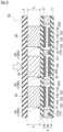
- Fig. 3(a) is a cross-sectional view showing a state in which a low load is applied to the pressure sensitive sensor unit 1A in Fig. 2
- Fig. 3(b) is a cross-sectional view showing a state in which a high load is applied to the pressure sensitive sensor unit 1A in Fig. 2 .
- the second base material 21 is bent downward at the first opening 31 by the load transmitted from the first load transmitting members 3A to 3D. That is, the first load transmitting members 3A to 3D concentrate the load on the first pressure sensitive sensors 2A to 2D.
- the connection bodies 22A to 22D formed on the lower surface of the second base material 21 are pressed downward to be electrically connected to the first and second electrode groups 13 and 14 of the first pressure sensitive sensors 2A to 2D.
- the second load transmitting member 4 since the amount of contraction of the first load transmitting members 3A to 3D is small, the second load transmitting member 4 is spaced apart from the plate member 5 and accordingly, the load is not transmitted from the plate member 5 to the second load transmitting member 4. Therefore, the second load transmitting member 4 does not press the second base material 21, and the connection body 22E is not pressed downward. That is, the third electrode 13E and the fourth electrode 14E of the first pressure sensitive sensor 2E are maintained in a state (off state) in which these are insulated from each other.
- the second base material 21 is bent downward at the second opening 32 by the load transmitted from the second load transmitting member 4.
- the connection body 22E is pressed downward to be electrically connected to the third and fourth electrodes 13E and 14E of the second pressure sensitive sensor 2E.
- the pressure sensitive sensor unit 1A only the first pressure sensitive sensors 2A to 2D are in the ON state when a low load is applied, whereas not only the first pressure sensitive sensors 2A to 2D but also the second pressure sensitive sensor 2E is in the ON state when a high load is applied.
- the first load transmitting members 3A to 3D are arranged on the upper surface of the second base material 21 so that the first load transmitting members 3A to 3D surround the second load transmitting member 4. That is, since the first pressure sensitive sensors 2A to 2D according to the present embodiment are arranged around the second pressure sensitive sensor 2E, the first load transmitting members 3A to 3D are also arranged around the second load transmitting member 4. Therefore, when a load is applied to the pressure sensitive sensor unit 1A, the load can be transmitted uniformly from the lower surface of the plate member 5 while stably supporting the plate member 5 by the plurality of first load transmitting members 3A to 3D arranged around the second load transmitting member 4. As a result, it is possible to detect the load accurately.
- Fig. 4 is a graph showing the relationship between the magnitude F of a load applied to the pressure sensitive sensor unit 1A according to the present embodiment and the resistance value R output from the pressure sensitive sensor unit 1A.
- the solid line indicates the combined resistance R 0 of the resistance value R x1 of the first pressure sensitive sensors 2A to 2D and the resistance value R 1 of the resistive body 16, and the broken line indicates the resistance value R x2 of the second pressure sensitive sensor 2E.
- the dashed line indicates the resistance value R output from the pressure sensitive sensor unit 1A, and in the present embodiment, the resistance value R is a resistance value between the first external terminal portion 122 and the second external terminal portion 172.
- the electrodes 13A to 13E and 14A to 14E of all the pressure sensitive sensors 2A to 2E are electrically insulated from each other, so that all the pressure sensitive sensors 2A to 2E are in the OFF state.
- a resistance value R d of several hundred M ⁇ is output from the pressure sensitive sensor unit 1A as the resistance value R.
- the first pressure sensitive sensors 2A to 2D are switched to the ON state.
- the resistance value between the connection bodies 22A to 22D and the first and second electrodes 13A to 13D and 14A to 14D exceeds a threshold value, so that the first pressure sensitive sensors 2A to 2D are maintained in the OFF state.
- the second pressure sensitive sensor 2E is maintained in the OFF state in the low load range.
- the first pressure sensitive sensors 2A to 2D are electrically connected in parallel to each other, and the resistive body 16 is electrically connected in series to the second electrode group 14 of the first pressure sensitive sensors 2A to 2D. Therefore, the resistance value R output from the pressure sensitive sensor unit 1A is the combined resistance R 0 of the resistance value R x1 of the first pressure sensitive sensors 2A to 2D and the resistance value R 1 of the resistive body 16.
- the second pressure sensitive sensor 2E is also switched to the ON state.
- the resistance value R x2 of the second pressure sensitive sensor 2E decreases. Since no resistive body is connected to the second pressure sensitive sensor 2E and the resistance value R 1 of the resistive body 16 described above is larger than the resistance value R x2 , the resistance value R x2 falls below the value of the combined resistance R 0 when the magnitude of the high load reaches a magnitude equal to or greater than a predetermined level.
- the resistance value R x2 falls below the value of the combined resistance R 0 described above, the current flowing through the second pressure sensitive sensor 2E becomes more dominant than the current flowing through the first pressure sensitive sensors 2A to 2D. Therefore, the resistance value R output from the pressure sensitive sensor unit 1A becomes the resistance value R x2 of the second pressure sensitive sensor 2E.
- the resistive body 16 in series to the second electrode group 14 by electrically connecting the resistive body 16 in series to the second electrode group 14, the range of the resistance value output in the low load range and the range of the resistance value output in the high load range can be distinguished from each other to avoid duplication.
- the resistance value R x2 of the second pressure sensitive sensor 2E saturates near the push-through resistance value R min as the magnitude of the load further increases, the resistance value R output from the pressure sensitive sensor unit 1A also saturates near the push-through resistance value R min . Therefore, the resistance value R of the pressure sensitive sensor unit 1A becomes an output shown by the dashed line in Fig. 4 .
- the pressure sensitive sensor unit 1A described above includes the first load transmitting member 3A to 3D for transmitting a low load to the first pressure sensitive sensor 2A to 2D and the second load transmitting member 4 for transmitting a high load to the second pressure sensitive sensor 2E. Therefore, since the pressure sensitive sensor unit 1A can obtain an output (resistance value R) in both the low load range and the high load range, it is possible to increase the detectable load range.
- the first load transmitting members 3A to 3D, the second load transmitting member 4, and the plate member 5 are arranged on the second base material 21 side of the upper membrane substrate 20, but the invention is not limited thereto.
- Fig. 5 is a cross-sectional view showing a first modification example of the pressure sensitive sensor unit according to the present embodiment.
- the first load transmitting members 3A to 3D, the second load transmitting member 4, and the plate member 5 may be arranged on the first base material 11 side of the lower membrane substrate 10.
- the second base material 21 when a low load is applied from the second base material 21 side, the load is transmitted to the first pressure sensitive sensors 2A to 2B by the first load transmitting members 3A to 3D, as in the embodiment described above. Then, when a high load is applied from the second base material 21 side, as in the embodiment described above, as the first load transmitting members 3A to 3D contract, the second load transmitting member 4 comes into contact with the plate member 5 and accordingly, the load is transmitted to the first pressure sensitive sensors 2A to 2B.
- a flexible one is used as the first base material 11 to which the load is transmitted from the first and second load transmitting members 3A to 3D and 4 a flexible one is used.
- the height T 1 of the first load transmitting members 3A to 3D is set to be higher than the height T 2 of the second load transmitting member 4 so that a load is less likely to be applied to the second pressure sensitive sensor 2E in the low load range, but the invention is not limited thereto.
- Fig. 6 is a cross-sectional view showing a second modification example of the pressure sensitive sensor unit according to the present embodiment.
- a second load transmitting member 4b may be made softer than the first load transmitting members 3A to 3D so that a load is less likely to be applied to the second pressure sensitive sensor 2E in the low load range.
- a material that makes up the second load transmitting member 4b a material having a low Young's modulus among the above-described sponge-like resin material, rubber material, and spring material may be used.
- interdigitated comb-shaped electrodes are used as the first and second electrodes 13A to 13E and 14A to 14E of the first pressure sensitive sensors 2A to 2E, but the shape of each electrode is not limited thereto.
- the shape of each electrode may be a shape shown in the following third modification example.
- Fig. 7(a) is an enlarged plan view showing a pressure sensitive sensor according to the third modification example of the pressure sensitive sensor unit according to the embodiment of the invention
- Fig. 7(b) is an enlarged plan view showing a lower membrane of the pressure sensitive sensor in Fig. 7(a)
- Fig. 7(c) is an enlarged plan view showing an upper membrane of the pressure sensitive sensor in Fig. 7(a) .
- a first pressure sensitive sensor 2d of a pressure sensitive sensor unit 1D according to the third modification example is a pressure sensitive sensor in which a resistance value between wiring patterns 62 and 66 changes according to the applied load.
- a first electrode 13d in the third modification example has wiring patterns 62 and 63, a resistive body 64, and comb-tooth patterns 65A to 65F.
- the wiring patterns 62 and 63 are formed by printing the low-resistance conductive paste described above on the upper surface of the first base material 11 of the lower membrane substrate 10d and solidifying (curing) the conductive paste.
- the wiring patterns 62 and 63 may be formed by etching a metal foil.
- the wiring pattern 62 extends linearly along the X direction in the diagram.
- An end portion 621 of the wiring pattern 62 is covered with the resistive body 64, and the comb-tooth pattern 65A is connected to the end portion 621.
- the wiring pattern 63 also extends linearly along the X direction in the diagram.
- An end portion 631 of the wiring pattern 63 is covered with the resistive body 64, and the comb-tooth pattern 65F is connected to the end portion 631.
- one wiring pattern 62 is connected to a power supply, whereas the other wiring pattern 63 is connected to the ground.
- the planar shapes of the wiring patterns 62 and 63 are not limited to the linear shapes described above so long as these are linear.
- the end portion 621 of the wiring pattern 62 and the end portion 631 of the wiring pattern 63 are arranged so as to be spaced apart from each other in the Y direction in the diagram.
- the resistive body 64 is provided along the Y direction in the diagram, so that one end portion 641 of the resistive body 64 covers the end portion 621 of the wiring pattern 62 and the other end portion 642 of the resistive body 64 covers the end portion 631 of the wiring pattern 63. Therefore, the wiring pattern 62 on one side and the wiring pattern 63 on the other side are electrically connected to each other through the resistive body 64.
- the resistive body 64 is formed by printing a high-resistance conductive paste on the upper surface of the base material 11 and then curing the conductive paste.
- the plurality of (six in this example) comb-tooth patterns 65A to 65F are formed by printing a low-resistance conductive paste on the first base material 11 and curing the conductive paste, similarly to the wiring patterns 62 and 63 described above.
- the comb-tooth patterns 65A to 65F may be formed by etching a metal foil.
- the comb-tooth patterns 65A to 65F are arranged substantially parallel to each other at distances therebetween in a facing region 611 of the first base material 11 facing the connection body 22A.
- the comb-tooth patterns 65A to 65F are aligned at distances therebetween from the inside to the outside in the facing region 611.
- the comb-tooth patterns 65A to 65F are arranged concentrically with respect to the center CP of a distal end portion 661 of the wiring pattern 66 in the facing region 611.
- a second electrode 14d in the third modification example is the wiring pattern 66.
- the wiring pattern 66 is also formed by printing a low-resistance conductive paste on the upper surface of the base material 11 and then curing the conductive paste, similarly to the wiring patterns 62 and 63 described above.
- the wiring pattern 66 may be formed by etching a metal foil.
- connection body 20A formed on the lower surface of the second base material 21 of the upper membrane substrate 20d is the same as that in the embodiment described above.
- connection body 22A when a load is applied, first, the connection body 22A comes into contact with the center CP of the distal end portion 661 of the wiring pattern 66 shown in Fig. 7(b) . Then, as bending at the first opening 31 of the second base material 21 increases, the connection body 22A comes into contact with the comb-tooth pattern 65F.
- the wiring pattern 66 detects a voltage that is almost the same potential as the ground, and a potential difference between the power supply voltage and the detected voltage of the wiring pattern 66 is output from a multimeter (not shown) or the like connected to the wiring patterns 62 and 66.
- the distance between one end portion 641 of the resistive body 64 and the connection position of the connection target decreases, resulting in a decrease in the resistance value between the wiring patterns 62 and 66. That is, in the first pressure sensitive sensor 2d according to the third modification example, since the resistance length (resistance value) of the resistive body 64 changes according to the magnitude of the applied load, the voltage detected by the wiring pattern 66 changes according to the magnitude of the load.
- the first pressure sensitive sensor 2d has the configuration shown in Fig. 7(a) .
- the invention is not limited thereto, and the second pressure sensitive sensor may also have the configuration as shown in Fig. 7(a) .
- the wiring pattern 63 may not be provided and the power supply and the ground may be connected to the wiring patterns 62 and 66.
- the wiring pattern 66 may be covered with the other end portion 642 of the resistive body 64. Even in these cases, the resistance value between the wiring patterns 62 and 66 changes according to the magnitude of the load.
- electrodes may be electrically connected to each other by direct contact between the electrodes.
- Fig. 8(a) is an enlarged cross-sectional view showing a pressure sensitive sensor according to a fourth modification example of the pressure sensitive sensor unit according to the present embodiment
- Fig. 8(b) is an enlarged plan view showing a lower membrane of the pressure sensitive sensor in Fig. 8(a)
- Fig. 8(c) is an enlarged plan view showing an upper membrane of the pressure sensitive sensor in Fig. 8(a) .
- a first pressure sensitive sensor 2e of a pressure sensitive sensor unit 1E includes a disk-shaped first electrode 13e formed on the upper surface of a first base material 11 of a lower membrane substrate 10e and a disk-shaped second electrode 14e formed on the lower surface of a second base material 21 of an upper membrane substrate 20e.
- the first electrode 13e and the second electrode 14e face each other at the first opening 31 of the spacer 30.
- the first and second electrodes 13e and 14e can be formed by printing and curing a pressure sensitive ink, for example.
- An example of the pressure sensitive ink is a quantum tunnel composite material using the quantum tunneling effect.
- other specific examples of the pressure sensitive ink include one containing conductive particles such as metal or carbon, elastic particles such as organic elastic filler or inorganic oxide filler, and a binder. The surface of the pressure sensitive ink is made uneven by the elastic particles.
- the first and second electrodes 13e and 14e may be formed by plating or patterning.
- the second base material 21 bends downward at the first opening 31, causing the first electrode 13e and the second electrode 14e to come into contact with each other and become electrically connected to each other.
- the fourth modification example an example has been described in which the first pressure sensitive sensor 2e has the configuration shown in Fig. 8(a) .
- the invention is not limited thereto, and the second pressure sensitive sensor may also have the configuration shown in Fig. 8(a) .
Landscapes
- Physics & Mathematics (AREA)
- General Physics & Mathematics (AREA)
- Force Measurement Appropriate To Specific Purposes (AREA)
- Measuring Fluid Pressure (AREA)
- Arrangements For Transmission Of Measured Signals (AREA)
Abstract
Description
- The present invention relates to a pressure sensitive sensor unit including a pressure sensitive sensor that detects the magnitude of an applied load.
- For designated countries in which incorporation by reference of documents is permitted, the contents of
Japanese Patent Application No. 2022-005182 filed in Japan on January 17, 2022 - A known pressure sensitive sensor includes an upper circuit board having a pair of interdigitated comb-shaped electrodes and a lower circuit board having a disk-shaped electrode facing the comb-shaped electrodes. In this pressure sensitive sensor, at least one of the three electrodes described above is a pressure sensitive resistive body (see, for example, Patent Document 1 (paragraphs [0002] to [0005] and Figs. 1(a) to 1(c))). In addition, another known pressure sensitive sensor includes an upper circuit board having a disk-shaped pressure sensitive resistive body and a lower circuit board having a disk-shaped counter electrode facing the pressure sensitive resistive body (see, for example, Patent Document 1 (paragraphs [0006] to [0008] and Figs. 2(a) to 2(c))).
- In the pressure sensitive sensors described above, when a load is applied from above to the upper circuit board, the electrodes arranged below the portion to which the load is applied come into direct contact with each other. Then, as the load increases further, the contact area between the electrodes increases and the resistance value decreases. The pressure sensitive sensors described above detect the magnitude of the load by using such a change in resistance value.
- Patent Document 1:
JP 2002-158103 A - Known pressure sensitive sensors such as those described above have a problem that the range of a load that can be detected may be narrow.
- A problem to be solved by the invention is to provide a pressure sensitive sensor unit capable of detecting a wide range of loads.
-
- [1] According to a first aspect of the invention, a pressure sensitive sensor unit includes: a first pressure sensitive sensor whose output changes according to a magnitude of an applied load; a second pressure sensitive sensor whose output changes according to a magnitude of an applied load; a plate member arranged so as to include the first and second pressure sensitive sensors in plan view; a first load transmitting member interposed between the first pressure sensitive sensor and the plate member; and a second load transmitting member interposed between the second pressure sensitive sensor and the plate member. The first load transmitting member transmits a load belonging to a first load range to the first pressure sensitive sensor. The second load transmitting member transmits a load belonging to a second load range larger than the first load to the second pressure sensitive sensor.
- [2] According to a second aspect of the invention, in the pressure sensitive sensor unit according to the first aspect, the second load transmitting member may not transmit a load belonging to the first load range to the second pressure sensitive sensor.
- [3] According to a third aspect of the invention, in the pressure sensitive sensor unit according to the first or second aspect, a height of the first load transmitting member may be higher than a height of the second load transmitting member, or the second load transmitting member may be softer than the first load transmitting member.
- [4] According to a fourth aspect of the invention, in the pressure sensitive sensor unit according to any one of the first to third aspects, the first pressure sensitive sensor may include first and second electrodes electrically connected to each other by application of a load, the second pressure sensitive sensor may include third and fourth electrodes electrically connected to each other by application of a load, and the pressure sensitive sensor unit may include a resistive body electrically connected in series to the first or second electrode of the first pressure sensitive sensor.
- [5] According to a fifth aspect of the invention, in the pressure sensitive sensor unit according to the fourth aspect, a resistance value of the resistive body may be larger than a resistance value in an ON state of the second pressure sensitive sensor.
- [6] According to a sixth aspect of the invention, in the pressure sensitive sensor unit according to the fourth or fifth aspect, the pressure sensitive sensor unit may include a plurality of the first pressure sensitive sensors. The pressure sensitive sensor unit may include: a first electrode group including a plurality of the first electrodes electrically connected to each other; and a second electrode group including a plurality of the second electrodes electrically connected to each other. The resistive body may be electrically connected in series to the first or second electrode group.
- [7] According to a seventh aspect of the invention, in the pressure sensitive sensor unit according to any one of the fourth to sixth aspects, the pressure sensitive sensor unit may include: a first base material; and a second base material facing the first base material. The first electrode may be provided on the first base material, and the second electrode may be provided on the first base material so as to face a first connection body provided on the second base material so as to face the first electrode or be provided on the second base material so as to face the first electrode.
- [8] According to an eighth aspect of the invention, in the pressure sensitive sensor unit according to any one of
aspects 4 to 6, the pressure sensitive sensor unit may include: a first base material; and a second base material facing the first base material. The third electrode may be provided on the first base material, and the fourth electrode may be provided on the first base material so as to face a second connection body provided on the second base material so as to face the third electrode or be provided on the second base material so as to face the third electrode. - [9] According to a ninth aspect of the invention, in the pressure sensitive sensor unit according to the seventh or eighth aspect, a height of the first load transmitting member may be higher than a height of the second load transmitting member, the first load transmitting member may be bonded to one of the first and second base materials and bonded to the plate member, and the second load transmitting member may be bonded to only one of the first base material, the second base material, and the plate member.
- [10] According to a tenth aspect of the invention, in the pressure sensitive sensor unit according to any one of the seventh to ninth aspects, the pressure sensitive sensor unit may include a spacer interposed between the first base material and the second base material. The spacer may include: a first opening in which the first and second electrodes of the first pressure sensitive sensor are housed; and a second opening in which the third and fourth electrodes of the second pressure sensitive sensor are housed. A width of the first opening may be larger than a width of the second opening.
- [11] According to an eleventh aspect of the invention, in the pressure sensitive sensor unit according to any one of the first to tenth aspects, the pressure sensitive sensor unit may include: a plurality of the first pressure sensitive sensors; and a plurality of the first load transmitting members. The plurality of first pressure sensitive sensors may be arranged around the second pressure sensitive sensor, and the plurality of first load transmitting members may be arranged around the second load transmitting member.
- The pressure sensitive sensor unit according to the invention includes the first load transmitting member that transmits a load belonging to the first load range to the first pressure sensitive sensor and the second load transmitting member that transmits a load belonging to the second load range larger than the first load range to the second pressure sensitive sensor. Therefore, since the pressure sensitive sensor unit according to the invention can detect a load in both the first range and the second range, it is possible to increase the detectable load range.
-
-
Fig. 1 is a plan view showing an example of a pressure sensitive sensor unit according to an embodiment of the invention; -
Fig. 2 is a cross-sectional view taken along the line II-II ofFig. 1 ; -
Fig. 3(a) is a cross-sectional view showing a state in which a low load is applied to the pressure sensitive sensor unit inFig. 2 , andFig. 3(b) is a cross-sectional view showing a state in which a high load is applied to the pressure sensitive sensor unit inFig. 2 ; -
Fig. 4 is a graph showing the relationship between the magnitude F of a load applied to the pressure sensitive sensor unit according to the embodiment of the invention and a resistance value R output from the pressure sensitive sensor unit; -
Fig. 5 is a cross-sectional view showing a first modification example of the pressure sensitive sensor unit according to the embodiment of the invention; -
Fig. 6 is a cross-sectional view showing a second modification example of the pressure sensitive sensor unit according to the embodiment of the invention; -
Fig. 7(a) is an enlarged plan view showing a pressure sensitive sensor according to a third modification example of the pressure sensitive sensor unit according to the embodiment of the invention,Fig. 7(b) is an enlarged plan view showing a lower membrane of the pressure sensitive sensor unit inFig. 7(a), and Fig. 7(c) is an enlarged plan view showing a spacer and an upper membrane of the pressure sensitive sensor unit inFig. 7(a) ; and -
Fig. 8 is an enlarged plan view showing a pressure sensitive sensor according to a fourth modification example of the pressure sensitive sensor unit according to the embodiment of the invention,Fig. 8(b) is an enlarged plan view showing a lower membrane of the pressure sensitive sensor inFig. 8(a), and Fig. 8(c) is an enlarged plan view showing an upper membrane of the pressure sensitive sensor inFig. 8(a) . - Hereinafter, an embodiment of the invention will be described with reference to the diagrams.
-
Fig. 1 is a plan view showing an example of a pressure sensitive sensor unit according to an embodiment of the invention.Fig. 2 is a cross-sectional view taken along the line II-II ofFig. 1 . In addition,Fig. 2 shows a pressure sensitive sensor unit in an unloaded state in which no load is applied. - A pressure
sensitive sensor unit 1A is a pressure sensitive sensor unit whose output changes according to the magnitude of the applied load. In the present embodiment, a resistance value is used as this output. In addition, this output is not limited to the resistance value, but may be, for example, a voltage value. - As shown in
Figs. 1 and2 , the pressuresensitive sensor unit 1A according to the present embodiment includes a pressuresensitive sensor sheet 2, a plurality of (four in this example) firstload transmitting members 3A to 3D, a secondload transmitting member 4, and aplate member 5. - The pressure
sensitive sensor sheet 2 includes pressuresensitive sensors 2A to 2E whose resistance values change according to the magnitude of the applied load. In the present embodiment, the first pressuresensitive sensors 2A to 2D are used to detect a load (low load) belonging to a first load range (low load range), and the second pressuresensitive sensor 2E is used to detect a load (high load) belonging to a second load range (high load range) larger than the first load range. - Here, the load range refers to a range of the magnitude of the load. The first load range is not particularly limited, but may be, for example, 20 gf to 500 gf, and the second load range is not particularly limited, but may be, for example, 500 gf to 2000 gf.
- As shown in
Figs. 1 and2 , the pressuresensitive sensor sheet 2 according to the present embodiment includes alower membrane substrate 10, anupper membrane substrate 20, and aspacer 30. - As shown in
Figs. 1 and2 , thelower membrane substrate 10 has afirst base material 11, afirst wiring pattern 12, a first electrode group 13 (13A to 13D), a second electrode group 14 (14A to 14D), athird electrode 13E, afourth electrode 14E, asecond wiring pattern 15, aresistive body 16, and athird wiring pattern 17. - The
first base material 11 of thelower membrane substrate 10 is a film-like member formed of a flexible and electrically insulating material. Examples of the material that makes up thefirst base material 11 include resin materials. More specifically, polyethylene terephthalate (PET) or polyethylene naphthalate (PEN) can be exemplified. In addition, thefirst base material 11 does not have to be flexible. - As shown in
Fig. 1 , thefirst wiring pattern 12 is formed on the upper surface of thefirst base material 11. Thefirst wiring pattern 12 in the present embodiment functions as a lead-out wiring that electrically connects the above-describedfirst electrode group 13 andthird electrode 13E to a power supply (not shown). - The
first wiring pattern 12 has afirst wiring portion 121a, asecond wiring portion 121b, and a firstexternal terminal portion 122. Thefirst wiring portion 121a has a U-shaped linear shape. One end of thefirst wiring portion 121a is connected to thesecond wiring portion 121b. Thesecond wiring portion 121b has an L-shaped linear shape, and one end of thesecond wiring portion 121b is connected to the firstexternal terminal portion 122. The firstexternal terminal portion 122 is a terminal portion that is electrically connected to a power supply (not shown). - The
first wiring pattern 12 is formed by printing a conductive paste on the upper surface of thefirst base material 11 and solidifying (curing) the conductive paste. The conductive paste is made by mixing conductive particles and a binder resin with water or a solvent and various additives. The conductive paste that makes up thefirst wiring pattern 12 is a low-resistance conductive paste having a relatively small electrical resistance value. In addition, the method of forming thefirst wiring pattern 12 is not particularly limited to the above. For example, instead of using the conductive paste, thefirst wiring pattern 12 may be formed by etching a metal foil. - Specific examples of conductive particles include silver, copper, nickel, tin, bismuth, zinc, indium, palladium, and alloys thereof. In addition, specific examples of the binder resin include acrylic resin, polyester resin, epoxy resin, vinyl resin, urethane resin, phenol resin, polyimide resin, silicone resin, and fluorine resin. In addition, examples of the solvent contained in the conductive paste include α-terpineol, butyl carbitol acetate, butyl carbitol, 1-decanol, butyl cellosolve, diethylene glycol monoethyl ether acetate, and tetradecane.
- Although not particularly limited, in the present embodiment, a silver paste containing silver as a main component of conductive particles or a copper paste containing copper as a main component of conductive particles is used as the low-resistance conductive paste. In addition, metal salts may be used as conductive particles contained in the conductive paste. As metal salts, salts of the metals described above can be mentioned. In addition, the binder resin may be omitted from the conductive paste described above. In addition, instead of the conductive paste described above, a conductive ink may be used.
- The method of applying the conductive paste is not particularly limited, but either a contact application method or a non-contact application method may be used. Specific examples of the contact application method include screen printing, gravure printing, offset printing, gravure offset printing, and flexographic printing. On the other hand, specific examples of the non-contact application method include inkjet printing, a spray coating method, a dispense coating method, and a jet dispensing method. In addition, the heat source for curing the conductive paste is not particularly limited, but examples thereof include an electric heating oven, an infrared oven, a far-infrared oven (IR), a near-infrared oven (NIR), and a laser irradiation device, and a heat treatment using a combination thereof may also be applied.
- The
first electrode group 13 is connected to thefirst wiring portion 121a of thefirst wiring pattern 12. Thefirst electrode group 13 includes a plurality of (four in this example)first electrodes 13A to 13D. In thefirst electrode group 13, thefirst electrodes 13A to 13D are arranged on thefirst wiring portion 121a so as to be electrically connected in parallel to each other. In addition, in the present embodiment, thefirst electrodes 13A to 13D are arranged so as to surround thethird electrode 13E and thefourth electrode 14E. - In the present embodiment, the
first electrodes 13A to 13D all have the same configuration. Therefore, the configuration of thefirst electrode 13A will be described herein as a representative example. - The
first electrode 13A is a comb-shaped electrode. Thefirst electrode 13A has aconnection wiring portion 131 and a plurality of (three in this example) comb-tooth portions 132. Theconnection wiring portion 131 is a linear portion extending along the Y direction in the diagram, and one end of theconnection wiring portion 131 is connected to thefirst wiring portion 121a of thefirst wiring pattern 12. - The plurality of comb-
tooth portions 132 are connected to the other end side of theconnection wiring portion 131. As shown inFigs. 1 and2 , the plurality of comb-tooth portions 132 are aligned in parallel along the Y direction in the diagrams, and protrude from theconnection wiring portion 131 in the +X direction in the diagrams. - The second electrode group 14 is arranged on the
first base material 11 so as to be adjacent to thefirst electrode group 13. The second electrode group 14 includes a plurality of (four in this example)second electrodes 14A to 14D. - The
second electrodes 14A to 14D are arranged adjacent to thefirst electrodes 13A to 13D, respectively. In addition, thesecond electrodes 14A to 14D are arranged slightly spaced apart from thefirst electrodes 13A to 13D so as to be electrically insulated from thefirst electrodes 13A to 13D. In the present embodiment, thesecond electrodes 14A to 14D are arranged so as to surround thethird electrode 13E and thefourth electrode 14E, similarly to thefirst electrodes 13A to 13D. - In addition, in the present embodiment, the plurality of first pressure
sensitive sensors 2A to 2D are arranged so as to surround the second pressuresensitive sensor 2E, but the invention is not limited to this. For example, in the pressuresensitive sensor unit 1A, the first pressure sensitive sensor and the second pressure sensitive sensor may be arranged alternately. - In the present embodiment, the
second electrodes 14A to 14D all have the same configuration. Therefore, the configuration of thesecond electrode 14A will be described herein as a representative example. - The
second electrode 14A has a planar shape point-symmetrical with respect to thefirst electrode 13A. Thesecond electrode 14A has aconnection wiring portion 141 and a plurality of (three in this example) comb-tooth portions 142. Theconnection wiring portion 141 is a linear portion extending along the Y direction in the diagram. The plurality of comb-tooth portions 142 are connected to one end side of theconnection wiring portion 141. The plurality of comb-tooth portions 142 are aligned along the Y direction in the diagram, and protrude from theconnection wiring portion 141 in the -X direction in the diagram. Then, the comb-tooth portions 142 are inserted between the comb-tooth portions 132 of thefirst electrode 13A, and face the comb-tooth portions 132 of thefirst electrode 13A along the Y direction in the diagram. - The above-described first and
second electrodes 13A to 13D and 14A to 14D are formed by printing a conductive paste on the upper surface of thefirst base material 11 and then solidifying (curing) the conductive paste. The conductive paste is a high-resistance conductive paste having a relatively high electrical resistance. In addition, instead of the conductive paste, a conductive ink may be used. - Examples of conductive particles contained in the conductive paste include carbon. Specific examples of the carbon include graphite and carbon black. In addition, specific examples of the binder resin and the solvent include the materials described above. In addition, the binder resin may be omitted from the conductive paste. The method of applying the conductive paste is not particularly limited, but either the contact application method or the non-contact application method described above may be used.
- The
second wiring pattern 15 is connected to the other ends of theconnection wiring portions 141 of thesecond electrodes 14A to 14D. Thesecond wiring pattern 15 electrically connects thesecond electrodes 14A to 14D and theresistive body 16 to each other. - The
second wiring pattern 15 is formed of the same material as thefirst wiring pattern 12 although there is no particular limitation thereto. In addition, although not particularly limited, thesecond wiring pattern 15 is formed by printing a conductive paste on the upper surface of thefirst base material 11 and solidifying (curing) the conductive paste, similarly to thefirst wiring pattern 12. - The
second wiring pattern 15 has athird wiring portion 151 and a first resistivebody connection portion 153. Thethird wiring portion 151 has a linear shape, and thesecond electrodes 14A to 14D are arranged on thethird wiring portion 151 so as to be electrically connected in parallel to each other. - The first resistive
body connection portion 153 is connected to the other end of thethird wiring portion 151. The first resistivebody connection portion 153 in the present embodiment is a land pattern that is wider than thethird wiring portion 151, although there is no particular limitation thereto. - The
resistive body 16 is connected to the first resistivebody connection portion 153. Theresistive body 16 in the present embodiment is arranged on thesecond wiring pattern 15 so as to be electrically connected in series to the second electrode group 14. Theresistive body 16 has a resistance value R1 (constant) larger than the resistance value Rx2 in the ON state of the second pressuresensitive sensor 2E. Theresistive body 16 is provided to make the combined resistance R0 (= R1 + Rx1) of the resistance value R1 of theresistive body 16 and the resistance value Rx1 in the ON state of the first pressuresensitive sensors 2A to 2D larger than the resistance value Rx2 in the ON state of the second pressuresensitive sensor 2E (R0 > Rx2). - In addition, the "ON state" of the first pressure
sensitive sensors 2A to 2D is a state in which thefirst electrodes 13A to 13D and thesecond electrodes 14A to 14D are electrically connected to each other throughconnection bodies 22A to 22D, and the "ON state" of the second pressuresensitive sensor 2E is a state in which thethird electrode 13E and thefourth electrode 14E are electrically connected to each other through aconnection body 22E. Here, in the present embodiment, "electrically connecting" a connection body and an electrode means a state in which the resistance value between the connection body and the electrode is equal to or less than a predetermined threshold value, and does not include a state in which the connection body and the electrode are simply in contact with each other. In addition, the resistance values Rx1 and Rx2 in the "ON state" are variables that change according to the magnitude of the load, as will be described later. - The
resistive body 16 may be a resistor although there is no particular limitation thereto. Alternatively, theresistive body 16 may be formed by printing a high-resistance conductive paste on the upper surface of thefirst base material 11 and solidifying (curing) the conductive paste. Examples of conductive particles contained in the conductive paste include the above-described carbon. In addition, specific examples of the binder resin and the solvent include the materials described above. In addition, the binder resin may be omitted from the conductive paste. The method of applying the conductive paste is not particularly limited, but either the contact application method or the non-contact application method described above may be used. - In the present embodiment, the
resistive body 16 is electrically connected in series to the second electrode group 14 and is arranged on the power supply side with respect to the first pressuresensitive sensors 2A to 2D, but is not limited thereto. For example, theresistive body 16 may be electrically connected in series to thefirst electrode group 13 and arranged on the power supply side with respect to the first pressuresensitive sensors 2A to 2D. - Although not particularly shown, specifically, in the
first wiring pattern 12 shown inFig. 1 , by interposing theresistive body 16 between thefirst wiring portion 121a and thesecond wiring portion 121b, theresistive body 16 can be electrically connected in series to all of thefirst electrodes first electrode group 13. In this case as well, the above-described combined resistance R0 (= R1 + Rx1) can be made larger than the resistance value Rx2 in the ON state of the second pressuresensitive sensor 2E (R0 > Rx2). - The comb-shaped
third electrode 13E is connected to the other end of thesecond wiring portion 121b of thefirst wiring pattern 12. Thethird electrode 13E has the same configuration as thefirst electrode 13A, and includes aconnection wiring portion 131 and a plurality of comb-tooth portions 132. However, theconnection wiring portion 131 of thethird electrode 13E extends along the X direction in the diagram. In addition, the comb-tooth portions 132 are aligned along the X direction in the diagram, and protrude from theconnection wiring portion 131 in the -Y direction in the diagram. - The comb-shaped
fourth electrode 14E is arranged on thefirst base material 11 so as to be adjacent to thethird electrode 13E. Thefourth electrode 14E is arranged slightly spaced apart from thethird electrode 13E so as to be electrically insulated from thethird electrode 13E. - The
fourth electrode 14E has the same configuration as thesecond electrode 14A, and includes aconnection wiring portion 141 and a plurality of comb-tooth portions 142. However, theconnection wiring portion 141 of thefourth electrode 14E extends along the X direction in the diagram. In addition, the comb-tooth portions 142 of thefourth electrode 14E are aligned along the X direction in the diagram, and protrude from theconnection wiring portion 141 in the +Y direction in the diagram. - The
third wiring pattern 17 is connected to theresistive body 16 and thefourth electrode 14E. Thethird wiring pattern 17 functions as a lead-out wiring that electrically connects the second electrode group 14 and thefourth electrode 14E to the ground (not shown). - The
third wiring pattern 17 has afourth wiring portion 171a, afifth wiring portion 171b, a secondexternal terminal portion 172, and a second resistivebody connection portion 173. Thefourth wiring portion 171a has a linear shape extending in the Y direction in the diagram, and one end of thefourth wiring portion 171a is connected to the secondexternal terminal portion 172. - The second
external terminal portion 172 is a terminal portion that is electrically connected to the ground (not shown). In addition, in the present embodiment, the firstexternal terminal portion 122 of thefirst wiring pattern 12 is electrically connected to a power supply (not shown) and the secondexternal terminal portion 172 of thethird wiring pattern 17 is connected to the ground (not shown), but the invention is not limited thereto. Contrary to the present embodiment, the firstexternal terminal portion 122 may be electrically connected to the ground (not shown), and the secondexternal terminal portion 172 may be connected to the power supply (not shown). - The other end of the
fourth wiring portion 171a is connected to the second resistivebody connection portion 173. The second resistivebody connection portion 173 is a land pattern that is wider than thefourth wiring portion 171a, although there is no particular limitation thereto. Theresistive body 16 is connected to the second resistivebody connection portion 173, and thefourth wiring portion 171a is electrically connected to the second electrode group 14 through theresistive body 16 and thethird wiring pattern 17. As a result, the second electrode group 14 is electrically connected to the ground (not shown). - The
fifth wiring portion 171b has a linear shape extending in the X direction in the diagram, and one end of thefifth wiring portion 171b is connected to thefourth wiring portion 171a. On the other hand, the other end of thefifth wiring portion 171b is connected to thefourth electrode 14E. Therefore, the fourth electrode 4E is electrically connected to the ground (not shown) through thethird wiring pattern 17. - The resistance value output from the pressure
sensitive sensor unit 1A according to the present embodiment is a resistance value between the firstexternal terminal portion 122 and the secondexternal terminal portion 172 although there is no particular limitation thereto. The resistance value can be obtained by using, for example, a resistance measuring device such as a tester connected to the firstexternal terminal portion 122 and the secondexternal terminal portion 172. - As shown in
Figs. 1 and2 , theupper membrane substrate 20 is arranged above thelower membrane substrate 10. Theupper membrane substrate 20 has asecond base material 21 and a plurality of (five in this example)connection bodies 22A to 22E. - The
second base material 21 of theupper membrane substrate 20 is a film-like member formed of a flexible and electrically insulating material. Examples of the material that makes up thesecond base material 21 include resin materials. More specifically, polyethylene terephthalate (PET) or polyethylene naphthalate (PEN) can be exemplified. In addition, a metal film may be used as thesecond base material 21. In this case, thesecond base material 21 may have the functions of theconnection bodies 22A to 22E, that is, thesecond base material 21 may also serve as theconnection bodies 22A to 22E. - As shown in
Figs. 1 and2 , the disk-shapedconnection bodies 22A to 22E are formed on the lower surface of thesecond base material 21. Theconnection bodies 22A to 22D are members that come into contact with thefirst electrodes 13A to 13D and thesecond electrodes 14A to 14D to electrically connect thefirst electrodes 13A to 13D and thesecond electrodes 14A to 14D to each other. That is, theconnection body 22A comes into contact with thefirst electrode 13A and thesecond electrode 14A to electrically connect thefirst electrode 13A and thesecond electrode 14A to each other. Theconnection body 22B comes into contact with thefirst electrode 13B and thesecond electrode 14B to electrically connect thefirst electrode 13B and thesecond electrode 14B to each other. Theconnection body 22C comes into contact with thefirst electrode 13C and thesecond electrode 14C to electrically connect thefirst electrode 13C and thesecond electrode 14C to each other. Theconnection body 22D comes into contact with thefirst electrode 13D and thesecond electrode 14D to electrically connect thefirst electrode 13D and thesecond electrode 14D to each other. In addition, theconnection body 22E is also a member that comes into contact with thethird electrode 13E and thefourth electrode 14E to electrically connect thethird electrode 13E and thefourth electrode 14E to each other. - All of the
connection bodies 22A to 22E are arranged so as to face parts of theconnection wiring portions tooth portions tooth portions - The
connection bodies 22A to 22E are formed by printing a low-resistance conductive paste on the lower surface of thesecond base material 21 and curing the low-resistance conductive paste, similarly to thefirst wiring pattern 12 described above. That is, theconnection bodies 22A to 22E are formed of a material having a lower electrical resistivity than the material that makes up the first tofourth electrodes 13A to 13E and 14A to 14E. - In addition, the
connection bodies 22A to 22E may have a protective layer covering the above-described layer that is formed by printing and curing a high-resistance conductive paste. This protective layer is formed by printing and curing the above-described high-resistance conductive paste. - The
spacer 30 is a film-like member formed of a flexible and electrically insulating material, similar to the first andsecond base materials spacer 30 include resin materials. More specifically, polyethylene terephthalate (PET) or polyethylene naphthalate (PEN) can be exemplified. Alternatively, a double-sided adhesive tape can be exemplified as thespacer 30. A double-sided adhesive tape having adhesive layers formed on both surfaces of a base material may be used, or a double-sided adhesive tape having only adhesive layers may be used. - As shown in
Figs. 1 and2 , thespacer 30 is interposed between thefirst base material 11 and thesecond base material 21, and thelower membrane substrate 10 and theupper membrane substrate 20 are stacked with thespacer 30 interposed therebetween. Specifically, the upper surface of thebase material 11 of thelower membrane substrate 10 and the lower surface of thespacer 30 are attached to each other through an adhesive layer (not shown), and the upper surface of thespacer 30 and the lower surface of thebase material 21 of theupper membrane substrate 20 are attached to each other through an adhesive layer (not shown). - The
spacer 30 has a plurality of (four in this example)first openings 31 and asecond opening 32. The plurality offirst openings 31 are arranged so as to surround thesecond opening 32, as shown inFig. 1 . In addition, when the first pressure sensitive sensor and the second pressure sensitive sensor are arranged alternately as described above, the first opening and the second opening are also arranged alternately. - Each of the
first openings 31 has a circular planar shape. Parts of theconnection wiring portions 131 of thefirst electrodes 13A to 13D, the comb-tooth portions 132 of thefirst electrodes 13A to 13D, parts of theconnection wiring portions 141 of thesecond electrodes 14A to 14D, and the comb-tooth portions 142 of thesecond electrodes 14A to 14D are housed in thefirst openings 31. In addition, theconnection bodies 22A to 22D of theupper membrane substrate 20 are also housed in thefirst openings 31. In addition, the diameters of theconnection bodies 22A to 22D may be larger than the inner diameter of thefirst opening 31. - When the
membrane substrates spacer 30 interposed therebetween, theconnection bodies 22A to 22D and the comb-tooth portions second electrodes 13A to 13D and 14A to 14D face each other with thefirst opening 31 interposed therebetween. In addition, similarly, theconnection bodies 22A to 22D and parts of theconnection wiring portions second electrodes 13A to 13D and 14A to 14D face each other. - The
second opening 32 also has a circular planar shape, and parts of theconnection wiring portions fourth electrodes tooth portions fourth electrodes second opening 32. In addition, theconnection body 22E of theupper membrane substrate 20 is also housed in thesecond opening 32. In addition, the diameter of theconnection body 22E may be larger than the inner diameter of thesecond opening 32. - In addition, when the
membrane substrates spacer 30 interposed therebetween, theconnection body 22E and the comb-tooth portions fourth electrodes second opening 32 interposed therebetween. In addition, similarly, theconnection body 22E and parts of theconnection wiring portions fourth electrodes - As shown in
Figs. 1 and2 , thespacer 30 ensures a distance between theconnection bodies 22A to 22D and the comb-tooth portions second electrodes 13A to 13D and 14A to 14D. In addition, thespacer 30 ensures a distance between theconnection body 22E and the comb-tooth portions fourth electrodes - Here, the
second opening 32 in the present embodiment has the same width as thefirst opening 31. That is, as shown inFig. 2 , the diameter D2 of thesecond opening 32 is the same as the diameter D1 of the first opening 31 (D1 = D2). - In addition, although the diameter D1 of the
first opening 31 and the diameter D2 of thesecond opening 32 are the same length in the present embodiment, the invention is not limited thereto. The diameter D1 of thefirst opening 31 may be larger than the diameter D2 of the second opening 32 (D1 > D2). Thus, the width of thefirst opening 31 is larger than the width of thesecond opening 32, so that thesecond base material 21 is likely to bend at thefirst opening 31. Therefore, since the magnitude of the on-load of the first pressuresensitive sensors 2A to 2D can be reduced, it is possible to improve the sensitivity of the first pressuresensitive sensors 2A to 2D in the low load range. In addition, the "on-load" is a load required to switch the pressure sensitive sensor from the OFF state to the ON state. - In addition, the planar shape of each of the first and
second openings connection bodies 22A to 22E or theelectrodes 13A to 13E and 14A to 14E are not particularly limited to those described above, and may be, for example, shapes corresponding to the shapes of the first andsecond openings - In addition, in the present embodiment, the thickness of the
spacer 30 is set so that theconnection bodies 22A to 22E are not in contact with the comb-tooth portions spacer 30 may be set so that theconnection bodies 22A to 22E are always in contact with the comb-tooth portions spacer 30 may be set so that theconnection bodies 22A to 22E are always in contact with theconnection wiring portions - In addition, in the present embodiment, all of the first pressure
sensitive sensors 2A to 2D and the second pressuresensitive sensor 2E are formed by themembrane substrates spacer 30 of the pressuresensitive sensor sheet 2. However, the invention is not limited thereto, and the first and second pressuresensitive sensors 2A to 2E may be formed by separate membrane substrates and spacers. That is, the pressure sensitive sensor unit may be a unit formed by a plurality of pressure sensitive sensor sheets. - In addition, in this case, since the electrodes formed on the base material are likely to bend by reducing the thickness of the spacer of the pressure sensitive sensor sheet in which the first pressure sensitive sensor for low load is formed, it is possible to improve the sensitivity of the sensor in the low load range. Alternatively, since the electrodes are likely to bend by reducing the thickness of the base material, it is possible to improve the sensitivity of the sensor in the low load range.
- In the pressure
sensitive sensor sheet 2 according to the present embodiment, theconnection bodies 22A to 22D and the first andsecond electrodes 13A to 13D and 14A to 14D form the first pressuresensitive sensors 2A to 2D and function asfirst detection units 135A to 135D that detect a load applied to the first pressuresensitive sensors 2A to 2D. That is, theconnection body 22A, thefirst electrode 13A, and thesecond electrode 14A form the first pressuresensitive sensor 2A and function as thefirst detection unit 135A that detects a load applied to the first pressuresensitive sensor 2A. Theconnection body 22B, thefirst electrode 13B, and thesecond electrode 14B form the first pressuresensitive sensor 2B and function as thefirst detection unit 135B that detects a load applied to the first pressuresensitive sensor 2B. Theconnection body 22C, thefirst electrode 13C, and thesecond electrode 14C form the first pressure sensitive sensor 2C and function as thefirst detection unit 135C that detects a load applied to the first pressure sensitive sensor 2C. Theconnection body 22D, thefirst electrode 13D, and thesecond electrode 14D form the first pressuresensitive sensor 2D and function as thefirst detection unit 135D that detects a load applied to the first pressuresensitive sensor 2D. On the other hand, theconnection body 22E and the third andfourth electrodes sensitive sensor 2E and function as asecond detection unit 135E that detects a load applied to the second pressuresensitive sensor 2E. - Specifically, when a load is applied to the
first detection units 135A to 135D of the first pressuresensitive sensor 2A to 2D, thesecond base material 21 bends downward at thefirst opening 31, and theconnection bodies 22A to 22D come into contact with the first andsecond electrodes 13A to 13D and 14A to 14D. Here, as the magnitude of the load applied to thefirst detection units 135A to 135D increases, the contact area between theconnection bodies 22A to 22D and the first andsecond electrodes 13A to 13D and 14A to 14D increases. Therefore, the resistance value Rx1 between the first andsecond electrodes 13A to 13D and 14A to 14D decreases. That is, in the first pressuresensitive sensors 2A to 2D, as the magnitude of the applied load increases, the resistance value Rx1 that is output decreases. - Similarly, even when a load is applied to the
second detection unit 135E of the second pressuresensitive sensor 2E, thesecond base material 21 bends downward at thesecond opening 32, and theconnection body 22E comes into contact with the third andfourth electrodes second detection unit 135E increases, the contact area between theconnection body 22E and the third andfourth electrodes fourth electrodes sensitive sensor 2E as well, as the magnitude of the applied load increases, the resistance value Rx2 that is output decreases. - In the present embodiment, the
first electrodes 13A to 13D and thethird electrode 13E have the same configuration, and thesecond electrodes 14A to 14D and thefourth electrode 14E have the same configuration. Therefore, the resistance value Rx1 in the ON state of the first pressuresensitive sensors 2A to 2D is approximately the same as the resistance value Rx2 in the ON state of the second pressuresensitive sensor 2E (Rx1 = Rx2). - In addition, in the present embodiment, the first pressure
sensitive sensors 2A to 2D are electrically connected in parallel to each other between thefirst wiring pattern 12 and thesecond wiring pattern 15. Then, the first pressuresensitive sensor 2E is electrically connected in parallel with the first pressuresensitive sensors 2A to 2D between thefirst wiring pattern 12 and thesecond wiring pattern 15. - A plurality of (four in this example) first
load transmitting members 3A to 3D and a secondload transmitting member 4 are provided on the upper surface of thesecond base material 21 of the pressuresensitive sensor sheet 2. The firstload transmitting members 3A to 3D are members (actuators) for transmitting a load to the first pressuresensitive sensors 2A to 2D. On the other hand, the secondload transmitting member 4 is a member (actuator) for transmitting a load to the second pressuresensitive sensor 2E. - In the present embodiment, the first
load transmitting members 3A to 3D and the secondload transmitting member 4 are members each having a circular planar shape and having elasticity. That is, the firstload transmitting members 3A to 3D and the secondload transmitting member 4 are members that contract when a load is applied but return to their initial shapes before the load is applied when the load is removed. In addition, the planar shapes of the firstload transmitting members 3A to 3D and the secondload transmitting member 4 are not limited to the circular shape. The planar shape is not limited to a circle, and may be, for example, an ellipse, an oval, a rectangle, or a polygon. In addition, the firstload transmitting members 3A to 3D and the secondload transmitting member 4 may be rigid bodies. - Specific examples of the member having elasticity as described above include a resin member, a rubber member, and a spring member. Among these, it is particularly preferable to use a sponge-like resin member containing fine bubbles.
- As shown in
Fig. 2 , the firstload transmitting members 3A to 3D are interposed between thefirst detection units 135A to 135D of the first pressuresensitive sensors 2A to 2D and theplate member 5. Specifically, the lower surfaces of the firstload transmitting members 3A to 3D are attached to the upper surface of thesecond base material 21 of theupper membrane substrate 20 through an adhesive layer (not shown), and the upper surfaces of the firstload transmitting members 3A to 3D are attached to the lower surface of theplate member 5 through an adhesive layer (not shown). That is, both the upper and lower surfaces of the firstload transmitting members 3A to 3D are fixed to thesecond base material 21 and theplate member 5. - In addition, the first
load transmitting members 3A to 3D are bonded to thesecond base material 21 and theplate member 5 through an adhesive layer, but the invention is not limited thereto. For example, the firstload transmitting members 3A to 3D may be bonded to thesecond base material 21 or theplate member 5 by being applied and formed thereon. - The second
load transmitting member 4 is interposed between thesecond detection unit 135E of the second pressuresensitive sensor 2E and theplate member 5. The lower surface of the secondload transmitting member 4 is attached to the upper surface of thesecond base material 21 of theupper membrane substrate 20 through an adhesive layer (not shown), but the upper surface of the secondload transmitting member 4 is spaced apart from theplate member 5. That is, only the lower surface of the secondload transmitting member 4 is fixed to thesecond base material 21. - In addition, the second
load transmitting member 4 is bonded to thesecond base material 21 through an adhesive layer, but the invention is not limited thereto. For example, the secondload transmitting member 4 may be bonded to thesecond base material 21 by being applied and formed thereon. In addition, the lower surface of the secondload transmitting member 4 is fixed to thesecond base material 21, but the invention is not limited thereto. The upper surface of the secondload transmitting member 4 may be bonded to theplate member 5, and the lower surface of the secondload transmitting member 4 may be spaced apart from thesecond base material 21. - The height T1 of the first
load transmitting members 3A to 3D is higher than the height T2 of the second load transmitting member 4 (T1 > T2). In this manner, by making a difference between the height T1 of the firstload transmitting members 3A to 3D and the height T2 of the secondload transmitting member 4, the load can be transmitted to the first pressuresensitive sensors 2A to 2D before the second pressuresensitive sensor 2E. That is, when a low load is applied to the pressuresensitive sensor unit 1A, the load is transmitted to the first pressuresensitive sensors 2A to 2D by the firstload transmitting members 3A to 3D, but the load is not transmitted to the second pressuresensitive sensor 2E by the secondload transmitting member 4. On the other hand, when a high load is applied to the pressuresensitive sensor unit 1A, the load is also transmitted to the second pressuresensitive sensor 2E by the secondload transmitting member 4. - The
plate member 5 overlaps the pressuresensitive sensor sheet 2 with the first and secondload transmitting members 3A to 3D interposed therebetween, and is arranged so as to include the first and second pressuresensitive sensors 2A to 2E in plan view. Theplate member 5 is a plate-shaped member formed of a material having a predetermined rigidity. By forming theplate member 5 with a member that is difficult to bend, it is possible to generate a uniform pressing force on the lower surface of theplate member 5. Examples of the material that makes up theplate member 5 include an ABS (acrylonitrile butadiene styrene) resin, glass, and a polycarbonate resin. - The load transmission by the first
load transmitting members 3A to 3D and the secondload transmitting member 4 will be specifically described with reference toFigs. 3(a) and 3(b). Fig. 3(a) is a cross-sectional view showing a state in which a low load is applied to the pressuresensitive sensor unit 1A inFig. 2 , andFig. 3(b) is a cross-sectional view showing a state in which a high load is applied to the pressuresensitive sensor unit 1A inFig. 2 . - As shown in
Fig. 3(a) , when a low load F1 is applied to the pressuresensitive sensor unit 1A from theplate member 5 side, the load is transmitted from theplate member 5 to the firstload transmitting members 3A to 3D bonded to the lower surface of theplate member 5. That is, the firstload transmitting members 3A to 3D are pressed in the -Z direction in the diagram by the lower surface of theplate member 5. - Then, the
second base material 21 is bent downward at thefirst opening 31 by the load transmitted from the firstload transmitting members 3A to 3D. That is, the firstload transmitting members 3A to 3D concentrate the load on the first pressuresensitive sensors 2A to 2D. As a result, at thefirst opening 31 of thespacer 30, theconnection bodies 22A to 22D formed on the lower surface of thesecond base material 21 are pressed downward to be electrically connected to the first andsecond electrode groups 13 and 14 of the first pressuresensitive sensors 2A to 2D. - On the other hand, since the amount of contraction of the first
load transmitting members 3A to 3D is small, the secondload transmitting member 4 is spaced apart from theplate member 5 and accordingly, the load is not transmitted from theplate member 5 to the secondload transmitting member 4. Therefore, the secondload transmitting member 4 does not press thesecond base material 21, and theconnection body 22E is not pressed downward. That is, thethird electrode 13E and thefourth electrode 14E of the first pressuresensitive sensor 2E are maintained in a state (off state) in which these are insulated from each other. - As shown in
Fig. 3(b) , when a high load F2 is applied to the pressuresensitive sensor unit 1A from theplate member 5 side, theplate member 5 is pressed further downward and the firstload transmitting members 3A to 3D contract significantly. Therefore, the lower surface of theplate member 5 comes into contact with the secondload transmitting member 4. That is, in addition to the firstload transmitting members 3A to 3D, the secondload transmitting member 4 is also pressed in the -Z direction in the diagram by the lower surface of theplate member 5. - The
second base material 21 is bent downward at thesecond opening 32 by the load transmitted from the secondload transmitting member 4. As a result, at thesecond opening 32 of thespacer 30, theconnection body 22E is pressed downward to be electrically connected to the third andfourth electrodes sensitive sensor 2E. - Thus, in the pressure
sensitive sensor unit 1A according to the present embodiment, only the first pressuresensitive sensors 2A to 2D are in the ON state when a low load is applied, whereas not only the first pressuresensitive sensors 2A to 2D but also the second pressuresensitive sensor 2E is in the ON state when a high load is applied. - In addition, as shown in
Figs. 1 and2 , the firstload transmitting members 3A to 3D are arranged on the upper surface of thesecond base material 21 so that the firstload transmitting members 3A to 3D surround the secondload transmitting member 4. That is, since the first pressuresensitive sensors 2A to 2D according to the present embodiment are arranged around the second pressuresensitive sensor 2E, the firstload transmitting members 3A to 3D are also arranged around the secondload transmitting member 4. Therefore, when a load is applied to the pressuresensitive sensor unit 1A, the load can be transmitted uniformly from the lower surface of theplate member 5 while stably supporting theplate member 5 by the plurality of firstload transmitting members 3A to 3D arranged around the secondload transmitting member 4. As a result, it is possible to detect the load accurately. - The change in the resistance value output from the pressure
sensitive sensor unit 1A as described above will be described with reference toFig. 4 in addition toFigs. 1 ,2 ,3(a) and 3(b) .Fig. 4 is a graph showing the relationship between the magnitude F of a load applied to the pressuresensitive sensor unit 1A according to the present embodiment and the resistance value R output from the pressuresensitive sensor unit 1A. In the graph ofFig. 4 , the solid line indicates the combined resistance R0 of the resistance value Rx1 of the first pressuresensitive sensors 2A to 2D and the resistance value R1 of theresistive body 16, and the broken line indicates the resistance value Rx2 of the second pressuresensitive sensor 2E. In addition, the dashed line indicates the resistance value R output from the pressuresensitive sensor unit 1A, and in the present embodiment, the resistance value R is a resistance value between the firstexternal terminal portion 122 and the secondexternal terminal portion 172. - First, as shown in
Fig. 2 , when there is no load, theelectrodes 13A to 13E and 14A to 14E of all the pressuresensitive sensors 2A to 2E are electrically insulated from each other, so that all the pressuresensitive sensors 2A to 2E are in the OFF state. In this case, as shown inFig. 4 , a resistance value Rd of several hundred MΩ is output from the pressuresensitive sensor unit 1A as the resistance value R. - Then, as shown in
Fig. 3(a) , when the low load F1 equal to or greater than a predetermined level is applied to the pressuresensitive sensor unit 1A, the first pressuresensitive sensors 2A to 2D are switched to the ON state. In other words, at the low load F1 equal to or lower than a predetermined level, the resistance value between theconnection bodies 22A to 22D and the first andsecond electrodes 13A to 13D and 14A to 14D exceeds a threshold value, so that the first pressuresensitive sensors 2A to 2D are maintained in the OFF state. In addition, the second pressuresensitive sensor 2E is maintained in the OFF state in the low load range. - At this time, as shown in
Fig. 1 , the first pressuresensitive sensors 2A to 2D are electrically connected in parallel to each other, and theresistive body 16 is electrically connected in series to the second electrode group 14 of the first pressuresensitive sensors 2A to 2D. Therefore, the resistance value R output from the pressuresensitive sensor unit 1A is the combined resistance R0 of the resistance value Rx1 of the first pressuresensitive sensors 2A to 2D and the resistance value R1 of theresistive body 16. - In this case, as shown in
Fig. 4 , as the magnitude of the load increases in the low load range, the resistance value Rx1 of the first pressuresensitive sensors 2A to 2D decreases, and finally the resistance value Rx1 saturates at the minimum resistance value (push-through resistance) Rmin. For this reason, as shown by the solid line in the graph ofFig. 4 , the combined resistance R0 also decreases as the magnitude of the load increases, and finally saturates near the resistance value Rmin + R1. - Then, as shown in
Fig. 3(b) , when the high load F2 is applied to the pressuresensitive sensor unit 1A, the second pressuresensitive sensor 2E is also switched to the ON state. As shown by the broken line in the graph ofFig. 4 , as the magnitude of the load increases in the high load range, the resistance value Rx2 of the second pressuresensitive sensor 2E decreases. Since no resistive body is connected to the second pressuresensitive sensor 2E and the resistance value R1 of theresistive body 16 described above is larger than the resistance value Rx2, the resistance value Rx2 falls below the value of the combined resistance R0 when the magnitude of the high load reaches a magnitude equal to or greater than a predetermined level. - When the resistance value Rx2 falls below the value of the combined resistance R0 described above, the current flowing through the second pressure
sensitive sensor 2E becomes more dominant than the current flowing through the first pressuresensitive sensors 2A to 2D. Therefore, the resistance value R output from the pressuresensitive sensor unit 1A becomes the resistance value Rx2 of the second pressuresensitive sensor 2E. Thus, in the present embodiment, by electrically connecting theresistive body 16 in series to the second electrode group 14, the range of the resistance value output in the low load range and the range of the resistance value output in the high load range can be distinguished from each other to avoid duplication. - Then, since the resistance value Rx2 of the second pressure
sensitive sensor 2E saturates near the push-through resistance value Rmin as the magnitude of the load further increases, the resistance value R output from the pressuresensitive sensor unit 1A also saturates near the push-through resistance value Rmin. Therefore, the resistance value R of the pressuresensitive sensor unit 1A becomes an output shown by the dashed line inFig. 4 . - The pressure
sensitive sensor unit 1A described above includes the firstload transmitting member 3A to 3D for transmitting a low load to the first pressuresensitive sensor 2A to 2D and the secondload transmitting member 4 for transmitting a high load to the second pressuresensitive sensor 2E. Therefore, since the pressuresensitive sensor unit 1A can obtain an output (resistance value R) in both the low load range and the high load range, it is possible to increase the detectable load range. - In addition, in the embodiment described above, the first
load transmitting members 3A to 3D, the secondload transmitting member 4, and theplate member 5 are arranged on thesecond base material 21 side of theupper membrane substrate 20, but the invention is not limited thereto. -
Fig. 5 is a cross-sectional view showing a first modification example of the pressure sensitive sensor unit according to the present embodiment. Like a pressuresensitive sensor unit 1B according to the first modification example, the firstload transmitting members 3A to 3D, the secondload transmitting member 4, and theplate member 5 may be arranged on thefirst base material 11 side of thelower membrane substrate 10. - In this case, when a low load is applied from the
second base material 21 side, the load is transmitted to the first pressuresensitive sensors 2A to 2B by the firstload transmitting members 3A to 3D, as in the embodiment described above. Then, when a high load is applied from thesecond base material 21 side, as in the embodiment described above, as the firstload transmitting members 3A to 3D contract, the secondload transmitting member 4 comes into contact with theplate member 5 and accordingly, the load is transmitted to the first pressuresensitive sensors 2A to 2B. In addition, in this case, it is preferable to make thesecond base material 21 difficult to bend. Specifically, two or moresecond base materials 21 may be stacked on thespacer 30, or the thickness of thesecond base material 21 may be increased. In addition, as thefirst base material 11 to which the load is transmitted from the first and secondload transmitting members 3A to 3D and 4, a flexible one is used. - In addition, in the embodiment described above, the height T1 of the first
load transmitting members 3A to 3D is set to be higher than the height T2 of the secondload transmitting member 4 so that a load is less likely to be applied to the second pressuresensitive sensor 2E in the low load range, but the invention is not limited thereto. -
Fig. 6 is a cross-sectional view showing a second modification example of the pressure sensitive sensor unit according to the present embodiment. As in a pressuresensitive sensor unit 1C according to the second modification example, a secondload transmitting member 4b may be made softer than the firstload transmitting members 3A to 3D so that a load is less likely to be applied to the second pressuresensitive sensor 2E in the low load range. As a material that makes up the secondload transmitting member 4b, a material having a low Young's modulus among the above-described sponge-like resin material, rubber material, and spring material may be used. - In addition, in this case, the height T1 of the first
load transmitting members 3A to 3D and the height T2 of the secondload transmitting member 4b are the same (T1 = T2). Since the firstload transmitting members 3A to 3D are harder than the secondload transmitting member 4b, a load is more easily transmitted to the firstload transmitting members 3A to 3D than to the secondload transmitting member 4b in the low load range. Therefore, in the second modification example as well, similarly to the embodiment described above, a load is less likely to be applied to the second pressuresensitive sensor 2E in the low load range. - In addition, in the embodiment described above, interdigitated comb-shaped electrodes are used as the first and
second electrodes 13A to 13E and 14A to 14E of the first pressuresensitive sensors 2A to 2E, but the shape of each electrode is not limited thereto. The shape of each electrode may be a shape shown in the following third modification example. -
Fig. 7(a) is an enlarged plan view showing a pressure sensitive sensor according to the third modification example of the pressure sensitive sensor unit according to the embodiment of the invention,Fig. 7(b) is an enlarged plan view showing a lower membrane of the pressure sensitive sensor inFig. 7(a), and Fig. 7(c) is an enlarged plan view showing an upper membrane of the pressure sensitive sensor inFig. 7(a) . - As shown in
Figs. 7(a) and 7(b) , a first pressuresensitive sensor 2d of a pressuresensitive sensor unit 1D according to the third modification example is a pressure sensitive sensor in which a resistance value betweenwiring patterns first electrode 13d in the third modification example haswiring patterns resistive body 64, and comb-tooth patterns 65A to 65F. - As shown in
Fig. 7(b) , thewiring patterns first base material 11 of thelower membrane substrate 10d and solidifying (curing) the conductive paste. In addition, instead of using the conductive paste, thewiring patterns - As shown in
Fig. 7(b) , thewiring pattern 62 extends linearly along the X direction in the diagram. Anend portion 621 of thewiring pattern 62 is covered with theresistive body 64, and the comb-tooth pattern 65A is connected to theend portion 621. Similarly, thewiring pattern 63 also extends linearly along the X direction in the diagram. Anend portion 631 of thewiring pattern 63 is covered with theresistive body 64, and the comb-tooth pattern 65F is connected to theend portion 631. Although not particularly shown, onewiring pattern 62 is connected to a power supply, whereas theother wiring pattern 63 is connected to the ground. In addition, the planar shapes of thewiring patterns - The
end portion 621 of thewiring pattern 62 and theend portion 631 of thewiring pattern 63 are arranged so as to be spaced apart from each other in the Y direction in the diagram. Theresistive body 64 is provided along the Y direction in the diagram, so that oneend portion 641 of theresistive body 64 covers theend portion 621 of thewiring pattern 62 and theother end portion 642 of theresistive body 64 covers theend portion 631 of thewiring pattern 63. Therefore, thewiring pattern 62 on one side and thewiring pattern 63 on the other side are electrically connected to each other through theresistive body 64. Theresistive body 64 is formed by printing a high-resistance conductive paste on the upper surface of thebase material 11 and then curing the conductive paste. - The plurality of (six in this example) comb-
tooth patterns 65A to 65F are formed by printing a low-resistance conductive paste on thefirst base material 11 and curing the conductive paste, similarly to thewiring patterns tooth patterns 65A to 65F may be formed by etching a metal foil. - The comb-
tooth patterns 65A to 65F are arranged substantially parallel to each other at distances therebetween in a facingregion 611 of thefirst base material 11 facing theconnection body 22A. The comb-tooth patterns 65A to 65F are aligned at distances therebetween from the inside to the outside in the facingregion 611. In addition, the comb-tooth patterns 65A to 65F are arranged concentrically with respect to the center CP of adistal end portion 661 of thewiring pattern 66 in the facingregion 611. - A
second electrode 14d in the third modification example is thewiring pattern 66. Thewiring pattern 66 is also formed by printing a low-resistance conductive paste on the upper surface of thebase material 11 and then curing the conductive paste, similarly to thewiring patterns wiring pattern 66 may be formed by etching a metal foil. - As shown in
Fig. 7(c) , the configuration of the connection body 20A formed on the lower surface of thesecond base material 21 of theupper membrane substrate 20d is the same as that in the embodiment described above. - In the first pressure
sensitive sensor 2d, when a load is applied, first, theconnection body 22A comes into contact with the center CP of thedistal end portion 661 of thewiring pattern 66 shown inFig. 7(b) . Then, as bending at thefirst opening 31 of thesecond base material 21 increases, theconnection body 22A comes into contact with the comb-tooth pattern 65F. - When the
connection body 22A is in contact with thewiring pattern 66 and the comb-tooth pattern 65F, thewiring pattern 66 detects a voltage that is almost the same potential as the ground, and a potential difference between the power supply voltage and the detected voltage of thewiring pattern 66 is output from a multimeter (not shown) or the like connected to thewiring patterns - Then, as the applied load increases, the bending of the
second base material 21 increases, and the connection target of theconnection body 22A expands to the outer comb-tooth patterns 65E to 65A. Therefore, the distance between oneend portion 641 of theresistive body 64 and the connection position of the connection target decreases, resulting in a decrease in the resistance value between thewiring patterns sensitive sensor 2d according to the third modification example, since the resistance length (resistance value) of theresistive body 64 changes according to the magnitude of the applied load, the voltage detected by thewiring pattern 66 changes according to the magnitude of the load. - In the third modification example, an example has been described in which the first pressure
sensitive sensor 2d has the configuration shown inFig. 7(a) . However, the invention is not limited thereto, and the second pressure sensitive sensor may also have the configuration as shown inFig. 7(a) . - In addition, although not particularly shown, the
wiring pattern 63 may not be provided and the power supply and the ground may be connected to thewiring patterns wiring pattern 63, thewiring pattern 66 may be covered with theother end portion 642 of theresistive body 64. Even in these cases, the resistance value between thewiring patterns - In addition, in the embodiment described above, a case has been described in which all of the first to fourth electrodes are formed on the same base material and the first to fourth electrodes are electrically connected to each other by the connection body, but the invention is not limited thereto. As in the following fourth modification example, electrodes may be electrically connected to each other by direct contact between the electrodes.
-
Fig. 8(a) is an enlarged cross-sectional view showing a pressure sensitive sensor according to a fourth modification example of the pressure sensitive sensor unit according to the present embodiment,Fig. 8(b) is an enlarged plan view showing a lower membrane of the pressure sensitive sensor inFig. 8(a), and Fig. 8(c) is an enlarged plan view showing an upper membrane of the pressure sensitive sensor inFig. 8(a) . - As shown in
Figs. 8(a) to 8(c) , a first pressuresensitive sensor 2e of a pressuresensitive sensor unit 1E according to the fourth modification example includes a disk-shapedfirst electrode 13e formed on the upper surface of afirst base material 11 of alower membrane substrate 10e and a disk-shapedsecond electrode 14e formed on the lower surface of asecond base material 21 of anupper membrane substrate 20e. - The
first electrode 13e and thesecond electrode 14e face each other at thefirst opening 31 of thespacer 30. The first andsecond electrodes second electrodes - When a load is applied to the first pressure
sensitive sensor 2e, thesecond base material 21 bends downward at thefirst opening 31, causing thefirst electrode 13e and thesecond electrode 14e to come into contact with each other and become electrically connected to each other. - In the fourth modification example, an example has been described in which the first pressure
sensitive sensor 2e has the configuration shown inFig. 8(a) . However, the invention is not limited thereto, and the second pressure sensitive sensor may also have the configuration shown inFig. 8(a) . - In addition, the embodiment described above is described to facilitate the understanding of the invention, and is not described to limit the invention. Therefore, each element disclosed in the above-described embodiment is intended to include all design changes or equivalents falling within the technical scope of the invention.
-
- 1A to 1E PRESSURE SENSITIVE SENSOR UNITS
- 2 PRESSURE SENSITIVE SENSOR SHEET
- 2A to 2D, 2d, 2e FIRST PRESSURE SENSITIVE SENSORS
- 2E SECOND PRESSURE SENSITIVE SENSOR
- 10, 10d, 10e LOWER MEMBRANE SUBSTRATES
- 11 BASE MATERIAL
- 12 FIRST WIRING PATTERN
- 121a, 121b FIRST AND SECOND WIRING PORTIONS
- 122 FIRST EXTERNAL TERMINAL PORTION
- 13 FIRST ELECTRODE GROUP
- 13A to 13D, 13d, 13e FIRST ELECTRODES
- 14 SECOND ELECTRODE GROUP
- 14A to 14D, 14d, 14e SECOND ELECTRODES
- 13E THIRD ELECTRODE
- 14E FOURTH ELECTRODE
- 131, 141 CONNECTION WIRING PORTION
- 132, 142 COMB-TOOTH PORTION
- 135A to 135D FIRST DETECTION UNITS
- 135E SECOND DETECTION UNIT
- 15 SECOND WIRING PATTERN
- 151 THIRD WIRING PORTION
- 153 FIRST RESISTIVE BODY CONNECTION PORTION
- 16 RESISTIVE BODY
- 17 THIRD WIRING PATTERN
- 171a, 171b FOURTH AND FIFTH WIRING PORTIONS
- 172 SECOND EXTERNAL TERMINAL PORTION
- 173 SECOND RESISTIVE BODY CONNECTION PORTION
- 62 WIRING PATTERN
- 621 END PORTION
- 63 WIRING PATTERN
- 631 END PORTION
- 64 RESISTIVE BODY
- 641, , 642 END PORTION
- 65A to 65F COMB-TOOTH PATTERNS
- 655 DETECTION UNIT
- 66 WIRING PATTERN
- 661 DISTAL END PORTION
- 20, 20e UPPER MEMBRANE SUBSTRATE
- 21 BASE MATERIAL
- 22A to 22E CONNECTION BODIES
- 30 SPACER
- 31 FIRST OPENING
- 32 SECOND OPENING
- 3A to 3D FIRST LOAD TRANSMITTING MEMBERS
- 4, 4b SECOND LOAD TRANSMITTING MEMBER
- 5 PLATE MEMBER
Claims (10)
- A pressure sensitive sensor unit, comprising:a first pressure sensitive sensor whose output changes according to a magnitude of an applied load;a second pressure sensitive sensor whose output changes according to a magnitude of an applied load;a plate member arranged so as to include the first and second pressure sensitive sensors in plan view;a first load transmitting member interposed between the first pressure sensitive sensor and the plate member; anda second load transmitting member interposed between the second pressure sensitive sensor and the plate member,wherein the first load transmitting member transmits a load belonging to a first load range to the first pressure sensitive sensor, andthe second load transmitting member transmits a load belonging to a second load range larger than the first load range to the second pressure sensitive sensor.
- The pressure sensitive sensor unit according to claim 1,wherein a height of the first load transmitting member is higher than a height of the second load transmitting member, orthe second load transmitting member is softer than the first load transmitting member.
- The pressure sensitive sensor unit according to claim 1 or 2,wherein the first pressure sensitive sensor includes first and second electrodes electrically connected to each other by application of a load,the second pressure sensitive sensor includes third and fourth electrodes electrically connected to each other by application of a load, andthe pressure sensitive sensor unit includes a resistive body electrically connected in series to the first or second electrode of the first pressure sensitive sensor.
- The pressure sensitive sensor unit according to claim 3,
wherein a resistance value of the resistive body is larger than a resistance value in an ON state of the second pressure sensitive sensor. - The pressure sensitive sensor unit according to claim 3 or 4,wherein the pressure sensitive sensor unit includes a plurality of the first pressure sensitive sensors,the pressure sensitive sensor unit includes:a first electrode group including a plurality of the first electrodes electrically connected to each other; anda second electrode group including a plurality of the second electrodes electrically connected to each other, andthe resistive body is electrically connected in series to the first or second electrode group.
- The pressure sensitive sensor unit according to any one of claims 3 to 5,
wherein the pressure sensitive sensor unit includes:a first base material; anda second base material facing the first base material,the first electrode is provided on the first base material, andthe second electrode is provided on the first base material so as to face a first connection body provided on the second base material so as to face the first electrode or is provided on the second base material so as to face the first electrode. - The pressure sensitive sensor unit according to any one of claims 3 to 6,
wherein the pressure sensitive sensor unit includes:a first base material; anda second base material facing the first base material,the third electrode is provided on the first base material, andthe fourth electrode is provided on the first base material so as to face a second connection body provided on the second base material so as to face the third electrode or is provided on the second base material so as to face the third electrode. - The pressure sensitive sensor unit according to claim 6 or 7,wherein a height of the first load transmitting member is higher than a height of the second load transmitting member,the first load transmitting member is bonded to at least one of the first and second base materials and bonded to the plate member, andthe second load transmitting member is bonded to only one of the first base material, the second base material, and the plate member.
- The pressure sensitive sensor unit according to any one of claims 6 to 8,wherein the pressure sensitive sensor unit includes a spacer interposed between the first base material and the second base material,the spacer includes:a first opening in which the first and second electrodes of the first pressure sensitive sensor are housed; anda second opening in which the third and fourth electrodes of the second pressure sensitive sensor are housed, anda width of the first opening is larger than a width of the second opening.
- The pressure sensitive sensor unit according to any one of claims 1 to 9,
wherein the pressure sensitive sensor unit includes:a plurality of the first pressure sensitive sensors; anda plurality of the first load transmitting members,the plurality of first pressure sensitive sensors are arranged around the second pressure sensitive sensor, andthe plurality of first load transmitting members are arranged around the second load transmitting member.
Applications Claiming Priority (2)
| Application Number | Priority Date | Filing Date | Title |
|---|---|---|---|
| JP2022005182 | 2022-01-17 | ||
| PCT/JP2022/046268 WO2023136041A1 (en) | 2022-01-17 | 2022-12-15 | Pressure sensitive sensor unit |
Publications (2)
| Publication Number | Publication Date |
|---|---|
| EP4467947A1 true EP4467947A1 (en) | 2024-11-27 |
| EP4467947A4 EP4467947A4 (en) | 2025-12-17 |
Family
ID=87278939
Family Applications (1)
| Application Number | Title | Priority Date | Filing Date |
|---|---|---|---|
| EP22920559.6A Pending EP4467947A4 (en) | 2022-01-17 | 2022-12-15 | PRESSURE SENSOR UNIT |
Country Status (6)
| Country | Link |
|---|---|
| US (1) | US20250102377A1 (en) |
| EP (1) | EP4467947A4 (en) |
| JP (1) | JP7710535B2 (en) |
| CN (1) | CN118511063A (en) |
| TW (1) | TW202334624A (en) |
| WO (1) | WO2023136041A1 (en) |
Family Cites Families (14)
| Publication number | Priority date | Publication date | Assignee | Title |
|---|---|---|---|---|
| JPH10214537A (en) * | 1997-01-30 | 1998-08-11 | Fujikura Ltd | Seating sensor and airbag control method |
| JP4131756B2 (en) * | 1998-03-25 | 2008-08-13 | 北陸電気工業株式会社 | Membrane switch |
| JP3980300B2 (en) | 2000-09-07 | 2007-09-26 | 株式会社フジクラ | Membrane pressure sensitive resistor and pressure sensor |
| JP2004028883A (en) * | 2002-06-27 | 2004-01-29 | Denso Corp | Pressure sensor |
| JP4830475B2 (en) * | 2005-12-14 | 2011-12-07 | 株式会社デンソー | Vehicle collision load measuring device and vehicle collision object determination device using the same |
| US8893561B2 (en) | 2009-05-06 | 2014-11-25 | Xsensor Technology Corporation | Dielectric textured elastomer in a pressure mapping system |
| KR101191800B1 (en) * | 2010-05-12 | 2012-10-16 | 이진욱 | Shoe insole for walk diagnosis |
| KR101283434B1 (en) | 2011-11-29 | 2013-07-08 | 이진욱 | Shoe insole sensor for walk diagnosis shoe insole flexible board in contact with the same, and shoe insole for walk diagnosis |
| JPWO2013146995A1 (en) * | 2012-03-30 | 2015-12-14 | 株式会社フジクラ | Pressure sensor and pressure sensor module |
| JP6394096B2 (en) | 2014-06-18 | 2018-09-26 | 大日本印刷株式会社 | Pressure sensor device |
| US9574955B2 (en) * | 2015-01-14 | 2017-02-21 | Nippon Mektron, Ltd. | Pressure sensing element having an insulating layer with an increased height from the substrate towards the opening |
| JP2017138224A (en) | 2016-02-04 | 2017-08-10 | 株式会社デンソー | Load sensor |
| JP6322247B2 (en) * | 2016-09-16 | 2018-05-09 | Nissha株式会社 | Pressure sensor |
| JP7099908B2 (en) * | 2018-08-30 | 2022-07-12 | トヨタ自動車株式会社 | Sensor systems, robot hands, sensor system calibration methods, and programs |
-
2022
- 2022-12-15 WO PCT/JP2022/046268 patent/WO2023136041A1/en not_active Ceased
- 2022-12-15 EP EP22920559.6A patent/EP4467947A4/en active Pending
- 2022-12-15 US US18/729,048 patent/US20250102377A1/en active Pending
- 2022-12-15 CN CN202280089014.8A patent/CN118511063A/en active Pending
- 2022-12-15 JP JP2023573926A patent/JP7710535B2/en active Active
- 2022-12-22 TW TW111149410A patent/TW202334624A/en unknown
Also Published As
| Publication number | Publication date |
|---|---|
| JPWO2023136041A1 (en) | 2023-07-20 |
| JP7710535B2 (en) | 2025-07-18 |
| US20250102377A1 (en) | 2025-03-27 |
| WO2023136041A1 (en) | 2023-07-20 |
| CN118511063A (en) | 2024-08-16 |
| TW202334624A (en) | 2023-09-01 |
| EP4467947A4 (en) | 2025-12-17 |
Similar Documents
| Publication | Publication Date | Title |
|---|---|---|
| US8368505B2 (en) | Switch using variable resistance layer to control state | |
| KR102253083B1 (en) | Film heater with capacitive power control pattern, film heater apparatus thereof | |
| TW200928937A (en) | Panel-type input device and electronic apparatus having the same | |
| EP3564800A1 (en) | Wiring body, wiring board and touch sensor | |
| CN116324357B (en) | Pressure sensor | |
| TWI476671B (en) | Touch panel | |
| EP4467947A1 (en) | Pressure sensitive sensor unit | |
| JP7470783B2 (en) | Variable resistor | |
| US20110114374A1 (en) | Electrode plate with conductive coat and panel-type input device | |
| JP2009129375A (en) | Panel type input device | |
| KR102199815B1 (en) | Plate heater having touch switch | |
| JP2005190125A (en) | Panel type input device | |
| CN120345041A (en) | Variable resistor and method for manufacturing variable resistor | |
| WO2026094320A1 (en) | Capacitance sensor having heater function and capacitance sensor unit | |
| WO2026053534A1 (en) | Pressure-sensitive sensor | |
| US20110226536A1 (en) | Flexible slide-touch controlling device and the related position determination method | |
| JP2008070938A (en) | Touch panel | |
| JP3139264U (en) | Coordinate reading device | |
| JP2020166326A (en) | Wiring body, wiring board, touch sensor, and manufacturing method of wiring body | |
| JP2007067006A (en) | Variable resistor | |
| HK1162775B (en) | Switch using variable resistance layer to control state | |
| JP2007059469A (en) | Variable resistor |
Legal Events
| Date | Code | Title | Description |
|---|---|---|---|
| STAA | Information on the status of an ep patent application or granted ep patent |
Free format text: STATUS: THE INTERNATIONAL PUBLICATION HAS BEEN MADE |
|
| PUAI | Public reference made under article 153(3) epc to a published international application that has entered the european phase |
Free format text: ORIGINAL CODE: 0009012 |
|
| STAA | Information on the status of an ep patent application or granted ep patent |
Free format text: STATUS: REQUEST FOR EXAMINATION WAS MADE |
|
| 17P | Request for examination filed |
Effective date: 20240703 |
|
| AK | Designated contracting states |
Kind code of ref document: A1 Designated state(s): AL AT BE BG CH CY CZ DE DK EE ES FI FR GB GR HR HU IE IS IT LI LT LU LV MC ME MK MT NL NO PL PT RO RS SE SI SK SM TR |
|
| DAV | Request for validation of the european patent (deleted) | ||
| DAX | Request for extension of the european patent (deleted) | ||
| A4 | Supplementary search report drawn up and despatched |
Effective date: 20251119 |
|
| RIC1 | Information provided on ipc code assigned before grant |
Ipc: G01L 1/20 20060101AFI20251113BHEP |