EP4467914A1 - Shower steam condenser - Google Patents
Shower steam condenser Download PDFInfo
- Publication number
- EP4467914A1 EP4467914A1 EP24177161.7A EP24177161A EP4467914A1 EP 4467914 A1 EP4467914 A1 EP 4467914A1 EP 24177161 A EP24177161 A EP 24177161A EP 4467914 A1 EP4467914 A1 EP 4467914A1
- Authority
- EP
- European Patent Office
- Prior art keywords
- panel
- flow channels
- fluid
- outlet
- shower
- Prior art date
- Legal status (The legal status is an assumption and is not a legal conclusion. Google has not performed a legal analysis and makes no representation as to the accuracy of the status listed.)
- Granted
Links
Images


Classifications
-
- F—MECHANICAL ENGINEERING; LIGHTING; HEATING; WEAPONS; BLASTING
- F28—HEAT EXCHANGE IN GENERAL
- F28D—HEAT-EXCHANGE APPARATUS, NOT PROVIDED FOR IN ANOTHER SUBCLASS, IN WHICH THE HEAT-EXCHANGE MEDIA DO NOT COME INTO DIRECT CONTACT
- F28D21/00—Heat-exchange apparatus not covered by any of the groups F28D1/00 - F28D20/00
- F28D21/0001—Recuperative heat exchangers
- F28D21/0012—Recuperative heat exchangers the heat being recuperated from waste water or from condensates
-
- F—MECHANICAL ENGINEERING; LIGHTING; HEATING; WEAPONS; BLASTING
- F28—HEAT EXCHANGE IN GENERAL
- F28B—STEAM OR VAPOUR CONDENSERS
- F28B1/00—Condensers in which the steam or vapour is separate from the cooling medium by walls, e.g. surface condenser
- F28B1/02—Condensers in which the steam or vapour is separate from the cooling medium by walls, e.g. surface condenser using water or other liquid as the cooling medium
-
- A—HUMAN NECESSITIES
- A47—FURNITURE; DOMESTIC ARTICLES OR APPLIANCES; COFFEE MILLS; SPICE MILLS; SUCTION CLEANERS IN GENERAL
- A47K—SANITARY EQUIPMENT; ACCESSORIES THEREFOR, e.g. TOILET ACCESSORIES
- A47K3/00—Baths; Showers; Appurtenances therefor
- A47K3/28—Showers or bathing douches
- A47K3/281—Accessories for showers or bathing douches, e.g. cleaning devices for walls or floors of showers
-
- E—FIXED CONSTRUCTIONS
- E03—WATER SUPPLY; SEWERAGE
- E03C—DOMESTIC PLUMBING INSTALLATIONS FOR FRESH WATER OR WASTE WATER; SINKS
- E03C1/00—Domestic plumbing installations for fresh water or waste water; Sinks
- E03C1/02—Plumbing installations for fresh water
- E03C1/04—Water-basin installations specially adapted to wash-basins or baths
- E03C1/0408—Water installations especially for showers
-
- E—FIXED CONSTRUCTIONS
- E03—WATER SUPPLY; SEWERAGE
- E03C—DOMESTIC PLUMBING INSTALLATIONS FOR FRESH WATER OR WASTE WATER; SINKS
- E03C1/00—Domestic plumbing installations for fresh water or waste water; Sinks
- E03C1/02—Plumbing installations for fresh water
- E03C1/04—Water-basin installations specially adapted to wash-basins or baths
- E03C1/044—Water-basin installations specially adapted to wash-basins or baths having a heating or cooling apparatus in the supply line
-
- E—FIXED CONSTRUCTIONS
- E04—BUILDING
- E04H—BUILDINGS OR LIKE STRUCTURES FOR PARTICULAR PURPOSES; SWIMMING OR SPLASH BATHS OR POOLS; MASTS; FENCING; TENTS OR CANOPIES, IN GENERAL
- E04H1/00—Buildings or groups of buildings for dwelling or office purposes; General layout, e.g. modular co-ordination or staggered storeys
- E04H1/12—Small buildings or other erections for limited occupation, erected in the open air or arranged in buildings, e.g. kiosks, waiting shelters for bus stops or for filling stations, roofs for railway platforms, watchmen's huts or dressing cubicles
- E04H1/125—Small buildings, arranged in other buildings
- E04H1/1266—Cubicles for dressing; Toilets
-
- F—MECHANICAL ENGINEERING; LIGHTING; HEATING; WEAPONS; BLASTING
- F28—HEAT EXCHANGE IN GENERAL
- F28D—HEAT-EXCHANGE APPARATUS, NOT PROVIDED FOR IN ANOTHER SUBCLASS, IN WHICH THE HEAT-EXCHANGE MEDIA DO NOT COME INTO DIRECT CONTACT
- F28D1/00—Heat-exchange apparatus having stationary conduit assemblies for one heat-exchange medium only, the media being in contact with different sides of the conduit wall, in which the other heat-exchange medium is a large body of fluid, e.g. domestic or motor car radiators
- F28D1/02—Heat-exchange apparatus having stationary conduit assemblies for one heat-exchange medium only, the media being in contact with different sides of the conduit wall, in which the other heat-exchange medium is a large body of fluid, e.g. domestic or motor car radiators with heat-exchange conduits immersed in the body of fluid
- F28D1/03—Heat-exchange apparatus having stationary conduit assemblies for one heat-exchange medium only, the media being in contact with different sides of the conduit wall, in which the other heat-exchange medium is a large body of fluid, e.g. domestic or motor car radiators with heat-exchange conduits immersed in the body of fluid with plate-like or laminated conduits
- F28D1/0308—Heat-exchange apparatus having stationary conduit assemblies for one heat-exchange medium only, the media being in contact with different sides of the conduit wall, in which the other heat-exchange medium is a large body of fluid, e.g. domestic or motor car radiators with heat-exchange conduits immersed in the body of fluid with plate-like or laminated conduits the conduits being formed by paired plates touching each other
-
- E—FIXED CONSTRUCTIONS
- E03—WATER SUPPLY; SEWERAGE
- E03C—DOMESTIC PLUMBING INSTALLATIONS FOR FRESH WATER OR WASTE WATER; SINKS
- E03C1/00—Domestic plumbing installations for fresh water or waste water; Sinks
- E03C2001/005—Installations allowing recovery of heat from waste water for warming up fresh water
-
- F—MECHANICAL ENGINEERING; LIGHTING; HEATING; WEAPONS; BLASTING
- F28—HEAT EXCHANGE IN GENERAL
- F28D—HEAT-EXCHANGE APPARATUS, NOT PROVIDED FOR IN ANOTHER SUBCLASS, IN WHICH THE HEAT-EXCHANGE MEDIA DO NOT COME INTO DIRECT CONTACT
- F28D21/00—Heat-exchange apparatus not covered by any of the groups F28D1/00 - F28D20/00
- F28D2021/0019—Other heat exchangers for particular applications; Heat exchange systems not otherwise provided for
- F28D2021/0035—Other heat exchangers for particular applications; Heat exchange systems not otherwise provided for for domestic or space heating, e.g. heating radiators
-
- F—MECHANICAL ENGINEERING; LIGHTING; HEATING; WEAPONS; BLASTING
- F28—HEAT EXCHANGE IN GENERAL
- F28F—DETAILS OF HEAT-EXCHANGE AND HEAT-TRANSFER APPARATUS, OF GENERAL APPLICATION
- F28F3/00—Plate-like or laminated elements; Assemblies of plate-like or laminated elements
- F28F3/02—Elements or assemblies thereof with means for increasing heat-transfer area, e.g. with fins, with recesses, with corrugations
- F28F3/04—Elements or assemblies thereof with means for increasing heat-transfer area, e.g. with fins, with recesses, with corrugations the means being integral with the element
- F28F3/048—Elements or assemblies thereof with means for increasing heat-transfer area, e.g. with fins, with recesses, with corrugations the means being integral with the element in the form of ribs integral with the element or local variations in thickness of the element, e.g. grooves, microchannels
Definitions
- the heat exchanger includes a panel having an inlet, an outlet, and a plurality of flow channels.
- the panel is disposed within the shower environment.
- the plurality of flow channels fluidly couples the inlet with the outlet.
- the panel is configured to condense steam to heat a fluid flowing through the plurality of flow channels.
- Another embodiment relates to a method of heating a fluid for a shower environment.
- the method includes providing a panel disposed within the shower environment, the panel including an inlet, an outlet, and a plurality of flow channels fluidly coupling the inlet with the outlet, condensing, by the panel, steam within an interior volume of the shower environment, receiving, by the inlet, a supply of the fluid from a fluid source, heating, by the panel, the fluid flowing through the plurality of flow channels, and supplying, by the outlet, the fluid heated by the condensed steam to a fixture of the shower environment, the fixture configured to direct the fluid to the interior volume.
- the shower environment includes a sidewall, a floor, an interior volume defined by the sidewall and the floor, a fixture configured to direct a fluid to the interior volume, and a heat exchanger including a panel disposed along the sidewall within the interior volume.
- the panel includes an inlet configured to receive a supply of the fluid at a first temperature, an outlet fluidly coupled with the fixture and configured to supply the fluid at a second temperature, and a plurality of flow channels fluidly coupling the inlet with the outlet.
- the panel is configured to condense steam to heat the fluid flowing through the plurality of flow channels such that the second temperature is greater than the first temperature.
- an improved shower system for capturing thermal energy from waste shower water may include positioning a shower steam condenser panel inside of a shower to condense steam to heat incoming cooler water.
- shower systems may utilize heat exchangers in a drain to capture thermal energy from waste shower water to heat incoming shower water. However, not all the thermal energy is captured as some thermal energy escapes the shower in the form of steam. Condensing steam from a shower to capture energy to heat incoming shower water would be advantageous.
- the present application relates generally to the field of condensing steam from a shower to heat incoming shower water.
- a shower environment e.g., shower, steam room, spa, etc.
- shower system 100 includes a heat exchanger, shown as shower steam condenser panel 105, according to an exemplary embodiment.
- the shower system 100 may be located in a bathroom in a residential or commercial building.
- the shower system 100 includes a floor 101 and a plurality of sidewalls 102 extending from the floor 101.
- the floor 101 is a ground surface.
- the plurality of sidewalls 102 and the floor 101 collectively define an interior volume 103 (e.g., a showering volume, a steaming volume, etc.) of the shower system 100.
- one or more of the sidewalls 102 includes a door movable between an open position and a closed position to provide selective access to the interior volume 103.
- the shower system 100 includes one or more fixtures 104 (e.g., shower heads, spray heads, spray faces, etc.) configured to receive a flow of fluid (e.g., water) and supply (e.g., direct, spray, mist, etc.) the flow of fluid within the interior volume 103 (e.g., in a direction towards a user in the interior volume 103).
- the fixture 104 is configured to supply steam within the interior volume 103.
- the shower steam condenser panel 105 is mounted to one or more of the sidewalls 102 and disposed within the interior volume 103 of the shower system 100 so that it may contact steam or water (e.g., steam produced by the shower system 100, water supplied from the fixture 104, etc.).
- the shower steam condenser panel 105 is mounted at another location within the interior volume 103.
- the shower steam condenser panel 105 may be substantially flat.
- the shower steam condenser panel 105 is configured to condense steam produced by the shower system 100 to heat incoming fluid (e.g., water supplied to the shower system 100 from a municipal water supply, a private well, rainwater harvesting, a hot water heater, fluid drained down a drain of the shower system 100, etc.).
- the steam and the steam condensed by the shower steam condenser panel 105 may be warmer than the incoming fluid.
- the shower steam condenser panel 105 is configured to facilitate transferring thermal energy from the warmer steam and condensed steam to the incoming fluid, thereby heating the incoming fluid.
- the warmer steam and condensed steam may contact an outer surface of one or more flow channels (e.g., flow channels 120, pipes, tubes, conduits, etc.) supplying the fluid to the fixture 104 and transfer heat thereto.
- the shower steam condenser panel 105 is positioned proximate the floor 101 on the sidewalls 102 of the shower system 100. In this manner, fluid that is splashing (e.g., after hitting the floor 101, after hitting or being redirected by a user, etc.) can be splashed onto the shower steam condenser panel 105.
- the shower steam condenser panel 105 may use the thermal energy from the splashing warm fluid that would otherwise be discarded in the drain to heat the incoming fluid.
- the shower steam condenser panel 105 may be decorative so as to enhance the user experience in the shower system 100. Additionally or alternatively, the shower steam condenser panel 105 may make a statement to users that the shower system 100 is energy efficient. This contrasts with a traditional heat exchanger that is located in a drain and cannot be seen by a user. Rather, the shower steam condenser panel 105 may be visible to the user and may notify users that the shower system 100 is energy efficient thereby improving the user experience. Since the shower steam condenser panel 105 may condense steam to heat incoming cooler fluid, the shower steam condenser panel 105 may reduce the amount of steam in a bathroom which may improve the user experience. The reduction in steam may also improve the longevity of fixtures and décor in a bathroom.
- the shower steam condenser panel 105 includes a front plate 110 and a back plate 115.
- the back plate 115 may be selectively coupled to the front plate 110 using one or more fasteners (e.g., bolts, screws, etc.).
- a front side of the front plate 110 e.g., a surface facing the interior volume 103 when installed
- the shower steam condenser panel 105 may be selectively coupled to one of the sidewalls 102 of the shower system 100 using one or more fasteners (e.g., bolts, screws, etc.).
- the shower steam condenser panel 105 is made of aluminum.
- the shower steam condenser panel 105 is made from another suitable material or combination of materials such as steel or another metal.
- the front plate 110 may be machined on a back side thereof to include flow channels 120.
- the flow channels 120 may be manufactured using computer numerical control (CNC) machining.
- the flow channels 120 extend between opposing edges of the front plate 110 (e.g., opposing vertical edges, left and right sides, etc.) along the height of the front plate 110.
- the steam condenser panel 105 includes a flow inlet, shown as inlet 125, and a flow outlet, shown as outlet 130.
- the steam condenser panel 105 (and the shower system 100) is configured to receive a supply of the fluid via the inlet 125.
- the flow channels 120 provide a flow path to direct the fluid received via the inlet 125 in a direction towards the outlet 130.
- the flow channels 120 may snake along the front plate 110 between the inlet 125 and the outlet 130.
- the outlet 130 is fluidly coupled with the fixture 104 such that, after flowing through the steam condenser panel 105, the fluid is supplied to the fixture 104 (e.g., directly to the fixture 104 without any intervening components other than a fluid conduit therebetween) and directed to the interior volume 103 of the shower system 100.
- the back plate 115 may be coupled with the front plate 110 to selectively enclose (e.g., separate, segregate, etc.) the flow channels 120 from the interior volume 103.
- the flow channels 120 are configured to direct the fluid from the inlet 125 to the outlet 130 and fluidly couple the inlet 125 with the outlet 130.
- the steam and condensed steam contacts an outer surface of flow channels 120 and transfers heat thereto (e.g., thermal energy transfer, conduction, convection, etc.), thereby heating the fluid flowing through the flow channels 120.
- the fluid may enter the steam condenser panel 105 via the inlet 125 at a first temperature and exit the steam condenser panel 105 via the outlet 130 at a second temperature greater than the first temperature.
- the fluid temperature at the inlet 125 may be about 55 degrees Fahrenheit (e.g., within 5% of 55 degrees Fahrenheit, about 50 degrees Fahrenheit, about 60 degrees Fahrenheit, etc.).
- the fluid temperature at the outlet 130 may be about 80 degrees Fahrenheit (e.g., within 5% of 80 degrees Fahrenheit, about 75 degrees Fahrenheit, about 85 degrees Fahrenheit, etc.).
- the flow channels 120 located at the inlet 125 and outlet 130 may include copper tubes at the inlet 125 and outlet 130.
- a perspective view of a shower steam condenser panel 105 is shown according to an exemplary embodiment.
- the flow channels 120 are configured to receive cooler fluid at the inlet 125, direct a flow of the fluid through the flow channels 120, and supply the heated fluid at the outlet 130.
- the outlet 130 is located vertically above the inlet 125 and laterally offset from the inlet 125. It may be advantageous for the water to flow in a generally upwards direction through the flow channels 120 because thermal gradients are preferred.
- air trapped in the flow channels 120 of the shower steam condenser panel 105 may be pushed out (e.g., removed or expelled from the shower steam condenser panel 105) more readily. The air trapped in the flow channels may inhibit the effectiveness of the thermal energy transfer to heat the fluid flowing through the flow channels 120. Therefore, removing the air trapped in the flow channels 120 increases the effectiveness of the thermal energy transfer to heat the fluid flowing through the flow channels 120.
- the flow channels 120 are machined on the back side of the front plate 110.
- the front plate 110 defines a thickness 135 of about 1 ⁇ 2" to 3 ⁇ 4".
- the flow channels 120 define a width 140 of about 1 ⁇ 2" and a depth 145 of about 3/8".
- the back side of the front plate 110 may include a space 150 (e.g., a shoulder) around an outer perimeter thereof (e.g., an outer perimeter of the flow channels 120) which defines a width 155 of about 1 ⁇ 2".
- the back side of the front plate 110 may include a space 160 (e.g., sidewalls of the flow channels 120) between the flow channels 120 which defines a width 165 of about 1 ⁇ 4".
- the back plate 115 of the shower steam condenser panel 105 may have a thickness 170 of about 1 ⁇ 4".
- the back plate 115 may be coupled to the front plate 110 using about 20 screws.
- the steam condenser panel 105 e.g., the thickness 135, the width 140, the depth 145, the width 155, the width 165, the thickness 170, etc.
- the steam condenser panel 105 is otherwise suitably dimensioned.
- Coupled means the joining of two members directly or indirectly to one another. Such joining may be stationary (e.g., permanent) or moveable (e.g., removable or releasable). Such joining may be achieved with the two members or the two members and any additional intermediate members being integrally formed as a single unitary body with one another or with the two members or the two members and any additional intermediate members being attached to one another.
Landscapes
- Engineering & Computer Science (AREA)
- Health & Medical Sciences (AREA)
- Public Health (AREA)
- Mechanical Engineering (AREA)
- General Engineering & Computer Science (AREA)
- Thermal Sciences (AREA)
- Physics & Mathematics (AREA)
- Life Sciences & Earth Sciences (AREA)
- Hydrology & Water Resources (AREA)
- Water Supply & Treatment (AREA)
- Architecture (AREA)
- General Health & Medical Sciences (AREA)
- Epidemiology (AREA)
- Structural Engineering (AREA)
- Civil Engineering (AREA)
- Bathtubs, Showers, And Their Attachments (AREA)
- Devices For Medical Bathing And Washing (AREA)
- Heat-Exchange Devices With Radiators And Conduit Assemblies (AREA)
Abstract
Description
- This application claims the benefit of and priority to
U.S. Provisional Patent Application No. 63/503,826, filed May 23, 2023 U.S. Patent Application No. 18/668,845, filed May 20, 2024 - Shower systems in which excess warm liquid from the shower is used to heat incoming cold water are gaining increased prominence as part of an effort to make showers more energy efficient and less wasteful.
- One embodiment relates to a heat exchanger for a shower environment. The heat exchanger includes a panel having an inlet, an outlet, and a plurality of flow channels. The panel is disposed within the shower environment. The plurality of flow channels fluidly couples the inlet with the outlet. The panel is configured to condense steam to heat a fluid flowing through the plurality of flow channels.
- Another embodiment relates to a method of heating a fluid for a shower environment. The method includes providing a panel disposed within the shower environment, the panel including an inlet, an outlet, and a plurality of flow channels fluidly coupling the inlet with the outlet, condensing, by the panel, steam within an interior volume of the shower environment, receiving, by the inlet, a supply of the fluid from a fluid source, heating, by the panel, the fluid flowing through the plurality of flow channels, and supplying, by the outlet, the fluid heated by the condensed steam to a fixture of the shower environment, the fixture configured to direct the fluid to the interior volume.
- Another embodiment relates a shower environment. The shower environment includes a sidewall, a floor, an interior volume defined by the sidewall and the floor, a fixture configured to direct a fluid to the interior volume, and a heat exchanger including a panel disposed along the sidewall within the interior volume. The panel includes an inlet configured to receive a supply of the fluid at a first temperature, an outlet fluidly coupled with the fixture and configured to supply the fluid at a second temperature, and a plurality of flow channels fluidly coupling the inlet with the outlet. The panel is configured to condense steam to heat the fluid flowing through the plurality of flow channels such that the second temperature is greater than the first temperature.
- The accompanying drawings are not intended to be drawn to scale. Like reference numbers and designations in the various drawings indicate like elements. For purposes of clarity, not every component can be labeled in every drawing. Understanding that these drawings depict only several implementations in accordance with the disclosure and therefore, not to be considered limiting of its scope, the disclosure will be described with additional specificity and detail through use of the accompanying drawings.
-
FIG. 1 shows a perspective view of a shower system including a shower steam condenser panel, according to an exemplary embodiment. -
FIG. 2 shows a cross-section view of the shower steam condenser panel ofFIG. 1 , according to an exemplary embodiment. -
FIG. 3 shows a front view of the shower steam condenser panel ofFIG. 1 with a front plate removed, according to an exemplary embodiment. -
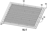
FIG. 4 shows a perspective view of the shower steam condenser panel ofFIG. 1 with the front plate removed, according to an exemplary embodiment. - According to an exemplary embodiment, an improved shower system for capturing thermal energy from waste shower water is discussed herein. The shower system may include positioning a shower steam condenser panel inside of a shower to condense steam to heat incoming cooler water.
- The various concepts introduced above and discussed in greater detail below may be implemented in any of numerous ways, as the described concepts are not limited to any particular manner of implementation. Examples of specific implementations and applications are provided primarily for illustrative purposes.
- Shower systems may utilize heat exchangers in a drain to capture thermal energy from waste shower water to heat incoming shower water. However, not all the thermal energy is captured as some thermal energy escapes the shower in the form of steam. Condensing steam from a shower to capture energy to heat incoming shower water would be advantageous. The present application relates generally to the field of condensing steam from a shower to heat incoming shower water.
- Referring to
FIG. 1 , a shower environment (e.g., shower, steam room, spa, etc.), shown asshower system 100, includes a heat exchanger, shown as showersteam condenser panel 105, according to an exemplary embodiment. Theshower system 100 may be located in a bathroom in a residential or commercial building. Theshower system 100 includes afloor 101 and a plurality ofsidewalls 102 extending from thefloor 101. In some embodiments, thefloor 101 is a ground surface. The plurality ofsidewalls 102 and thefloor 101 collectively define an interior volume 103 (e.g., a showering volume, a steaming volume, etc.) of theshower system 100. In some embodiments, one or more of thesidewalls 102 includes a door movable between an open position and a closed position to provide selective access to theinterior volume 103. As shown, theshower system 100 includes one or more fixtures 104 (e.g., shower heads, spray heads, spray faces, etc.) configured to receive a flow of fluid (e.g., water) and supply (e.g., direct, spray, mist, etc.) the flow of fluid within the interior volume 103 (e.g., in a direction towards a user in the interior volume 103). In some embodiments, thefixture 104 is configured to supply steam within theinterior volume 103. - As shown in
FIG. 1 , the showersteam condenser panel 105 is mounted to one or more of thesidewalls 102 and disposed within theinterior volume 103 of theshower system 100 so that it may contact steam or water (e.g., steam produced by theshower system 100, water supplied from thefixture 104, etc.). In some embodiments, the showersteam condenser panel 105 is mounted at another location within theinterior volume 103. The showersteam condenser panel 105 may be substantially flat. The showersteam condenser panel 105 is configured to condense steam produced by theshower system 100 to heat incoming fluid (e.g., water supplied to theshower system 100 from a municipal water supply, a private well, rainwater harvesting, a hot water heater, fluid drained down a drain of theshower system 100, etc.). The steam and the steam condensed by the showersteam condenser panel 105 may be warmer than the incoming fluid. The showersteam condenser panel 105 is configured to facilitate transferring thermal energy from the warmer steam and condensed steam to the incoming fluid, thereby heating the incoming fluid. By way of example, the warmer steam and condensed steam may contact an outer surface of one or more flow channels (e.g.,flow channels 120, pipes, tubes, conduits, etc.) supplying the fluid to thefixture 104 and transfer heat thereto. - As shown in
FIG. 1 , the showersteam condenser panel 105 is positioned proximate thefloor 101 on thesidewalls 102 of theshower system 100. In this manner, fluid that is splashing (e.g., after hitting thefloor 101, after hitting or being redirected by a user, etc.) can be splashed onto the showersteam condenser panel 105. The showersteam condenser panel 105 may use the thermal energy from the splashing warm fluid that would otherwise be discarded in the drain to heat the incoming fluid. - The shower
steam condenser panel 105 may be decorative so as to enhance the user experience in theshower system 100. Additionally or alternatively, the showersteam condenser panel 105 may make a statement to users that theshower system 100 is energy efficient. This contrasts with a traditional heat exchanger that is located in a drain and cannot be seen by a user. Rather, the showersteam condenser panel 105 may be visible to the user and may notify users that theshower system 100 is energy efficient thereby improving the user experience. Since the showersteam condenser panel 105 may condense steam to heat incoming cooler fluid, the showersteam condenser panel 105 may reduce the amount of steam in a bathroom which may improve the user experience. The reduction in steam may also improve the longevity of fixtures and décor in a bathroom. - Referring to
FIG. 2 , a cross-section view of the showersteam condenser panel 105 is shown, according to an exemplary embodiment. The showersteam condenser panel 105 includes afront plate 110 and aback plate 115. Theback plate 115 may be selectively coupled to thefront plate 110 using one or more fasteners (e.g., bolts, screws, etc.). A front side of the front plate 110 (e.g., a surface facing theinterior volume 103 when installed) may be decorative to enhance the user experience. The showersteam condenser panel 105 may be selectively coupled to one of thesidewalls 102 of theshower system 100 using one or more fasteners (e.g., bolts, screws, etc.). In some embodiments, the showersteam condenser panel 105 is made of aluminum. In other embodiments, the showersteam condenser panel 105 is made from another suitable material or combination of materials such as steel or another metal. - The
front plate 110 may be machined on a back side thereof to includeflow channels 120. Theflow channels 120 may be manufactured using computer numerical control (CNC) machining. Theflow channels 120 extend between opposing edges of the front plate 110 (e.g., opposing vertical edges, left and right sides, etc.) along the height of thefront plate 110. As shown inFIGS. 3 and4 , thesteam condenser panel 105 includes a flow inlet, shown asinlet 125, and a flow outlet, shown asoutlet 130. The steam condenser panel 105 (and the shower system 100) is configured to receive a supply of the fluid via theinlet 125. Theflow channels 120 provide a flow path to direct the fluid received via theinlet 125 in a direction towards theoutlet 130. By way of example, theflow channels 120 may snake along thefront plate 110 between theinlet 125 and theoutlet 130. Theoutlet 130 is fluidly coupled with thefixture 104 such that, after flowing through thesteam condenser panel 105, the fluid is supplied to the fixture 104 (e.g., directly to thefixture 104 without any intervening components other than a fluid conduit therebetween) and directed to theinterior volume 103 of theshower system 100. Theback plate 115 may be coupled with thefront plate 110 to selectively enclose (e.g., separate, segregate, etc.) theflow channels 120 from theinterior volume 103. - The
flow channels 120 are configured to direct the fluid from theinlet 125 to theoutlet 130 and fluidly couple theinlet 125 with theoutlet 130. As the fluid flows through theflow channels 120, the steam and condensed steam contacts an outer surface offlow channels 120 and transfers heat thereto (e.g., thermal energy transfer, conduction, convection, etc.), thereby heating the fluid flowing through theflow channels 120. By way of example, the fluid may enter thesteam condenser panel 105 via theinlet 125 at a first temperature and exit thesteam condenser panel 105 via theoutlet 130 at a second temperature greater than the first temperature. The fluid temperature at theinlet 125 may be about 55 degrees Fahrenheit (e.g., within 5% of 55 degrees Fahrenheit, about 50 degrees Fahrenheit, about 60 degrees Fahrenheit, etc.). The fluid temperature at theoutlet 130 may be about 80 degrees Fahrenheit (e.g., within 5% of 80 degrees Fahrenheit, about 75 degrees Fahrenheit, about 85 degrees Fahrenheit, etc.). In some embodiments, theflow channels 120 located at theinlet 125 andoutlet 130 may include copper tubes at theinlet 125 andoutlet 130. - Referring to
FIG. 4 , a perspective view of a showersteam condenser panel 105 is shown according to an exemplary embodiment. As discussed in greater detail above, theflow channels 120 are configured to receive cooler fluid at theinlet 125, direct a flow of the fluid through theflow channels 120, and supply the heated fluid at theoutlet 130. As shown, theoutlet 130 is located vertically above theinlet 125 and laterally offset from theinlet 125. It may be advantageous for the water to flow in a generally upwards direction through theflow channels 120 because thermal gradients are preferred. Additionally, air trapped in theflow channels 120 of the showersteam condenser panel 105 may be pushed out (e.g., removed or expelled from the shower steam condenser panel 105) more readily. The air trapped in the flow channels may inhibit the effectiveness of the thermal energy transfer to heat the fluid flowing through theflow channels 120. Therefore, removing the air trapped in theflow channels 120 increases the effectiveness of the thermal energy transfer to heat the fluid flowing through theflow channels 120. - As shown in
FIGS. 2-4 , theflow channels 120 are machined on the back side of thefront plate 110. Thefront plate 110 defines athickness 135 of about ½" to ¾". Theflow channels 120 define awidth 140 of about ½" and adepth 145 of about 3/8". The back side of thefront plate 110 may include a space 150 (e.g., a shoulder) around an outer perimeter thereof (e.g., an outer perimeter of the flow channels 120) which defines awidth 155 of about ½". Additionally or alternatively, the back side of thefront plate 110 may include a space 160 (e.g., sidewalls of the flow channels 120) between theflow channels 120 which defines awidth 165 of about ¼". Theback plate 115 of the showersteam condenser panel 105 may have athickness 170 of about ¼". Theback plate 115 may be coupled to thefront plate 110 using about 20 screws. In some embodiments, the steam condenser panel 105 (e.g., thethickness 135, thewidth 140, thedepth 145, thewidth 155, thewidth 165, thethickness 170, etc.) is otherwise suitably dimensioned. - It should be noted that the term "example" as used herein to describe various embodiments is intended to indicate that such embodiments are possible examples, representations, and/or illustrations of possible embodiments.
- Various numerical values herein are provided for reference purposes only. Unless otherwise indicated, all numbers expressing quantities of properties, parameters, conditions, and so forth, used in the specification and claims are to be understood as being modified in all instances by the term "about" or "approximately." Accordingly, unless indicated to the contrary, the numerical parameters set forth in the following specification are approximations. Any numerical parameter should at least be construed in light of the number reported significant digits and by applying ordinary rounding techniques. The term "about" or "approximately" when used before a numerical designation, e.g., a quantity and/or an amount including range, indicates approximations which may vary by ( + ) or ( - ) 10%, 5%, or 1%.
- As will be understood by one of skill in the art, for any and all purposes, particularly in terms of providing a written description, all ranges disclosed herein also encompass any and all possible subranges and combinations of subranges thereof. Any listed range can be easily recognized as sufficiently describing and enabling the same range being broken down into at least equal halves, thirds, quarters, fifths, tenths, etc. As a non-limiting example, each range discussed herein can be readily broken down into a lower third, middle third and upper third, etc. As will also be understood by one skilled in the art all language such as "up to," "at least," "greater than," "less than," and the like include the number recited and refer to ranges which can be subsequently broken down into subranges as discussed above. Finally, as will be understood by one skilled in the art, a range includes each individual member.
- As utilized herein, the term "substantially" and similar terms are intended to have a broad meaning in harmony with the common and accepted usage by those of ordinary skill in the art to which the subject matter of this disclosure pertains. It should be understood by those of skill in the art who review this disclosure that these terms are intended to allow a description of certain features described and claimed without restricting the scope of these features. Accordingly, these terms should be interpreted as indicating that insubstantial or inconsequential modifications or alterations of the subject matter described and claimed are considered to be within the scope of the invention as recited in the appended claims.
- The terms "coupled," "connected," and the like as used herein mean the joining of two members directly or indirectly to one another. Such joining may be stationary (e.g., permanent) or moveable (e.g., removable or releasable). Such joining may be achieved with the two members or the two members and any additional intermediate members being integrally formed as a single unitary body with one another or with the two members or the two members and any additional intermediate members being attached to one another.
- It is important to note that the construction and arrangement of the various exemplary embodiments are illustrative only. Those skilled in the art who review this disclosure will readily appreciate that many modifications are possible (e.g., variations in sizes, dimensions, structures, shapes and proportions of the various elements, values of parameters, mounting arrangements, use of materials, colors, orientations, etc.) without materially departing from the novel teachings and advantages of the subject matter described herein. Other substitutions, modifications, changes and omissions may also be made in the design, assembly and arrangement of the various exemplary embodiments without departing from the scope of the embodiments described herein.
- While this specification contains implementation details, these should not be construed as limitations on the scope of any embodiment or of what may be claimed, but rather as descriptions of features specific to particular implementations of particular embodiments. Certain features described in this specification in the context of separate implementations can also be implemented in combination in a single implementation. Conversely, various features described in the context of a single implementation can also be implemented in multiple implementations separately or in any suitable subcombination. Moreover, although features may be described above as acting in certain combinations and even initially claimed as such, one or more features from a claimed combination can in some cases be excised from the combination, and the claimed combination may be directed to a subcombination or variation of a subcombination.
Claims (15)
- A heat exchanger for a shower environment, comprising:a panel disposed within the shower environment, and including:an inlet;an outlet; anda plurality of flow channels fluidly coupling the inlet with the outlet;wherein the panel is configured to condense steam to heat a fluid flowing through the plurality of flow channels.
- The heat exchanger of claim 1, wherein the shower environment includes a sidewall and a floor defining an interior volume of the shower environment, and wherein the panel is disposed along the sidewall within the interior volume, optionally wherein the panel is configured for vertical placement along the sidewall and proximate the floor of the shower environment.
- The heat exchanger of claim 2, wherein the shower environment includes a fixture configured to direct the fluid to the interior volume, and wherein the outlet is fluidly coupled with the fixture.
- The heat exchanger of any one of claims 1 to 3, wherein the plurality of flow channels extends between opposing edges of the panel along a height of the panel.
- The heat exchanger of any one of the preceding claims, wherein the outlet is positioned vertically above the inlet.
- The heat exchanger of any one of the preceding claims, wherein each flow channel of the plurality of flow channels defines a width of about 0.5 inches and/or a depth of about 0.375 inches.
- The heat exchanger of any one of the preceding claims, wherein the inlet is configured to receive a supply of fluid at a first temperature, and wherein the outlet is configured to supply the fluid at a second temperature greater than the first temperature, optionally wherein the first temperature is about 55 degrees Fahrenheit, and wherein the second temperature is about 80 degrees Fahrenheit.
- The heat exchanger of any one of the preceding claims, further comprising a back plate configured to selectively couple with the panel, optionally wherein the back plate is configured to enclose the plurality of flow channels.
- A method of heating a fluid for a shower environment, the method comprising:providing a panel disposed within the shower environment, the panel including:an inlet;an outlet; anda plurality of flow channels fluidly coupling the inlet with the outlet;condensing, by the panel, steam within an interior volume of the shower environment;receiving, by the inlet, a supply of the fluid from a fluid source;heating, by the panel, the fluid flowing through the plurality of flow channels; andsupplying, by the outlet, the fluid heated by the condensed steam to a fixture of the shower environment, the fixture configured to direct the fluid to the interior volume.
- The method of claim 9, wherein heating the fluid flowing through the plurality of flow channels includes the condensed steam contacting on outer surface of the plurality of flow channels.
- The method of claim 9 or claim 10, wherein the plurality of flow channels extends between opposing edges of the panel along a height of the panel.
- The method of claim 9, claim 10 or claim 11, wherein the fluid received by the inlet is received at a first temperature, and wherein the fluid supplied by the outlet is supplied at a second temperature greater than the first temperature.
- A shower environment comprising:a sidewall;a floor;an interior volume defined by the sidewall and the floor;a fixture configured to direct a fluid to the interior volume; anda heat exchanger including a panel disposed along the sidewall within the interior volume, the panel including:an inlet configured to receive a supply of the fluid at a first temperature;an outlet fluidly coupled with the fixture and configured to supply the fluid at a second temperature; anda plurality of flow channels fluidly coupling the inlet with the outlet;wherein the panel is configured to condense steam to heat the fluid flowing through the plurality of flow channels such that the second temperature is greater than the first temperature.
- The heat exchanger of any one of claims 1 to 8 or claim 13, wherein the steam contacts an outer surface of the plurality of flow channels, and wherein the panel is configured to transfer thermal energy from the steam contacting the outer surface of the plurality of flow channels to the fluid flowing through the plurality of flow channels, thereby heating the fluid.
- The heat exchanger of claim 13 or claim 14 when dependent on claim 13, wherein the heat exchanger includes a back plate configured to selectively couple with the panel to enclose the plurality of flow channels or the method of any one of claims 9 to 12, further comprising providing a back plate configured to selectively couple with the panel to enclose the plurality of flow channels.
Applications Claiming Priority (2)
| Application Number | Priority Date | Filing Date | Title |
|---|---|---|---|
| US202363503826P | 2023-05-23 | 2023-05-23 | |
| US18/668,845 US20240393061A1 (en) | 2023-05-23 | 2024-05-20 | Shower Steam Condenser |
Publications (2)
| Publication Number | Publication Date |
|---|---|
| EP4467914A1 true EP4467914A1 (en) | 2024-11-27 |
| EP4467914B1 EP4467914B1 (en) | 2026-04-22 |
Family
ID=91193571
Family Applications (1)
| Application Number | Title | Priority Date | Filing Date |
|---|---|---|---|
| EP24177161.7A Active EP4467914B1 (en) | 2023-05-23 | 2024-05-21 | Shower steam condenser |
Country Status (3)
| Country | Link |
|---|---|
| US (1) | US20240393061A1 (en) |
| EP (1) | EP4467914B1 (en) |
| CN (1) | CN119022677A (en) |
Citations (4)
| Publication number | Priority date | Publication date | Assignee | Title |
|---|---|---|---|---|
| US8104532B2 (en) * | 2010-03-29 | 2012-01-31 | Jeremiah Cardone | Shower heat exchanger with clog-removable drain |
| US20130031716A1 (en) * | 2011-08-01 | 2013-02-07 | Hall David R | Shower Chamber Configured to Retain Heat |
| US8904638B2 (en) * | 2009-02-25 | 2014-12-09 | Ying Lin Cai | Heat exchanger for a bathing shower |
| US20160076230A1 (en) * | 2014-09-11 | 2016-03-17 | Ying Lin Cai | Thermal energy exchanger for bathing shower water |
Family Cites Families (2)
| Publication number | Priority date | Publication date | Assignee | Title |
|---|---|---|---|---|
| US3594063A (en) * | 1969-04-01 | 1971-07-20 | Charles M Smillie | Water-heated mirror |
| CN215637515U (en) * | 2021-07-22 | 2022-01-25 | 中联西北工程设计研究院有限公司 | Phase-change waste heat recovery ventilation heating system |
-
2024
- 2024-05-20 US US18/668,845 patent/US20240393061A1/en active Pending
- 2024-05-21 EP EP24177161.7A patent/EP4467914B1/en active Active
- 2024-05-23 CN CN202410645104.1A patent/CN119022677A/en active Pending
Patent Citations (4)
| Publication number | Priority date | Publication date | Assignee | Title |
|---|---|---|---|---|
| US8904638B2 (en) * | 2009-02-25 | 2014-12-09 | Ying Lin Cai | Heat exchanger for a bathing shower |
| US8104532B2 (en) * | 2010-03-29 | 2012-01-31 | Jeremiah Cardone | Shower heat exchanger with clog-removable drain |
| US20130031716A1 (en) * | 2011-08-01 | 2013-02-07 | Hall David R | Shower Chamber Configured to Retain Heat |
| US20160076230A1 (en) * | 2014-09-11 | 2016-03-17 | Ying Lin Cai | Thermal energy exchanger for bathing shower water |
Also Published As
| Publication number | Publication date |
|---|---|
| CN119022677A (en) | 2024-11-26 |
| EP4467914B1 (en) | 2026-04-22 |
| US20240393061A1 (en) | 2024-11-28 |
Similar Documents
| Publication | Publication Date | Title |
|---|---|---|
| US8104532B2 (en) | Shower heat exchanger with clog-removable drain | |
| EP2746710B1 (en) | Heat exchanger, and energy recovery device and energy recovery system comprising heat exchanger | |
| NO850428L (en) | ROOF OR WALL CONSTRUCTION | |
| GB2416829A (en) | A heat exchange unit utilising waste water to heat cold incoming mains water | |
| CN100489432C (en) | Novel slab type spiral heat exchanger | |
| US7077155B2 (en) | Hot water recirculating system | |
| EP2791431B1 (en) | Domestic appliance | |
| EP2791430B1 (en) | Domestic appliance | |
| US20240393061A1 (en) | Shower Steam Condenser | |
| CA2775456C (en) | Shower heat exchanger with clog-removable drain | |
| EP2791429B1 (en) | Domestic appliance | |
| WO2007086641A3 (en) | Indoor unit of air conditioner | |
| CN201346170Y (en) | Multifunctional bath tub | |
| WO2010109156A2 (en) | Shower waste device | |
| CN210980088U (en) | Machine and air conditioning unit in air conditioning | |
| JP6095312B2 (en) | Exhaust hood and combustion equipment | |
| CN219995546U (en) | Electromagnetic hot water module boiler | |
| EP4520880A1 (en) | System for recovering heat from water from a shower, bath tub or similar | |
| RU56583U1 (en) | HEATING DEVICE | |
| CN215838593U (en) | Novel anti-scalding multifunctional shower | |
| CN206310955U (en) | A kind of asynchronous instant waste-heat recovery device of plate heat exchange of heat pipe formula | |
| CN219624532U (en) | Bath waste water heat replacement device and electric water heating system | |
| CN2493903Y (en) | Wall hanging radiation water heater for kitchen or bathroom | |
| RU153599U1 (en) | CAST IRON SECTION RADIATOR | |
| CA3239125A1 (en) | Heat exchanger water trap |
Legal Events
| Date | Code | Title | Description |
|---|---|---|---|
| PUAI | Public reference made under article 153(3) epc to a published international application that has entered the european phase |
Free format text: ORIGINAL CODE: 0009012 |
|
| STAA | Information on the status of an ep patent application or granted ep patent |
Free format text: STATUS: THE APPLICATION HAS BEEN PUBLISHED |
|
| AK | Designated contracting states |
Kind code of ref document: A1 Designated state(s): AL AT BE BG CH CY CZ DE DK EE ES FI FR GB GR HR HU IE IS IT LI LT LU LV MC ME MK MT NL NO PL PT RO RS SE SI SK SM TR |
|
| STAA | Information on the status of an ep patent application or granted ep patent |
Free format text: STATUS: REQUEST FOR EXAMINATION WAS MADE |
|
| 17P | Request for examination filed |
Effective date: 20250520 |
|
| GRAP | Despatch of communication of intention to grant a patent |
Free format text: ORIGINAL CODE: EPIDOSNIGR1 |
|
| STAA | Information on the status of an ep patent application or granted ep patent |
Free format text: STATUS: GRANT OF PATENT IS INTENDED |
|
| INTG | Intention to grant announced |
Effective date: 20260217 |
|
| GRAS | Grant fee paid |
Free format text: ORIGINAL CODE: EPIDOSNIGR3 |
|
| GRAA | (expected) grant |
Free format text: ORIGINAL CODE: 0009210 |
|
| STAA | Information on the status of an ep patent application or granted ep patent |
Free format text: STATUS: THE PATENT HAS BEEN GRANTED |
|
| P01 | Opt-out of the competence of the unified patent court (upc) registered |
Free format text: CASE NUMBER: UPC_APP_0006407_4467914/2026 Effective date: 20260223 |
|
| AK | Designated contracting states |
Kind code of ref document: B1 Designated state(s): AL AT BE BG CH CY CZ DE DK EE ES FI FR GB GR HR HU IE IS IT LI LT LU LV MC ME MK MT NL NO PL PT RO RS SE SI SK SM TR |
|
| REG | Reference to a national code |
Ref country code: CH Ref legal event code: F10 Free format text: ST27 STATUS EVENT CODE: U-0-0-F10-F00 (AS PROVIDED BY THE NATIONAL OFFICE) Effective date: 20260422 Ref country code: GB Ref legal event code: FG4D |
|
| REG | Reference to a national code |
Ref country code: DE Ref legal event code: R096 Ref document number: 602024004096 Country of ref document: DE |