EP4467884A1 - Heat pump - Google Patents
Heat pump Download PDFInfo
- Publication number
- EP4467884A1 EP4467884A1 EP23175729.5A EP23175729A EP4467884A1 EP 4467884 A1 EP4467884 A1 EP 4467884A1 EP 23175729 A EP23175729 A EP 23175729A EP 4467884 A1 EP4467884 A1 EP 4467884A1
- Authority
- EP
- European Patent Office
- Prior art keywords
- container
- heat exchanger
- heat
- refrigerant
- wall
- Prior art date
- Legal status (The legal status is an assumption and is not a legal conclusion. Google has not performed a legal analysis and makes no representation as to the accuracy of the status listed.)
- Pending
Links
Images





Classifications
-
- F—MECHANICAL ENGINEERING; LIGHTING; HEATING; WEAPONS; BLASTING
- F24—HEATING; RANGES; VENTILATING
- F24F—AIR-CONDITIONING; AIR-HUMIDIFICATION; VENTILATION; USE OF AIR CURRENTS FOR SCREENING
- F24F11/00—Control or safety arrangements
- F24F11/30—Control or safety arrangements for purposes related to the operation of the system, e.g. for safety or monitoring
- F24F11/32—Responding to malfunctions or emergencies
- F24F11/36—Responding to malfunctions or emergencies to leakage of heat-exchange fluid
-
- F—MECHANICAL ENGINEERING; LIGHTING; HEATING; WEAPONS; BLASTING
- F24—HEATING; RANGES; VENTILATING
- F24F—AIR-CONDITIONING; AIR-HUMIDIFICATION; VENTILATION; USE OF AIR CURRENTS FOR SCREENING
- F24F1/00—Room units for air-conditioning, e.g. separate or self-contained units or units receiving primary air from a central station
- F24F1/0003—Room units for air-conditioning, e.g. separate or self-contained units or units receiving primary air from a central station characterised by a split arrangement, wherein parts of the air-conditioning system, e.g. evaporator and condenser, are in separately located units
-
- F—MECHANICAL ENGINEERING; LIGHTING; HEATING; WEAPONS; BLASTING
- F24—HEATING; RANGES; VENTILATING
- F24F—AIR-CONDITIONING; AIR-HUMIDIFICATION; VENTILATION; USE OF AIR CURRENTS FOR SCREENING
- F24F13/00—Details common to, or for air-conditioning, air-humidification, ventilation or use of air currents for screening
- F24F13/20—Casings or covers
-
- F—MECHANICAL ENGINEERING; LIGHTING; HEATING; WEAPONS; BLASTING
- F24—HEATING; RANGES; VENTILATING
- F24H—FLUID HEATERS, e.g. WATER OR AIR HEATERS, HAVING HEAT-GENERATING MEANS, e.g. HEAT PUMPS, IN GENERAL
- F24H15/00—Control of fluid heaters
- F24H15/10—Control of fluid heaters characterised by the purpose of the control
- F24H15/12—Preventing or detecting fluid leakage
-
- F—MECHANICAL ENGINEERING; LIGHTING; HEATING; WEAPONS; BLASTING
- F24—HEATING; RANGES; VENTILATING
- F24D—DOMESTIC- OR SPACE-HEATING SYSTEMS, e.g. CENTRAL HEATING SYSTEMS; DOMESTIC HOT-WATER SUPPLY SYSTEMS; ELEMENTS OR COMPONENTS THEREFOR
- F24D11/00—Central heating systems using heat accumulated in storage masses
- F24D11/02—Central heating systems using heat accumulated in storage masses using heat pumps
- F24D11/0214—Central heating systems using heat accumulated in storage masses using heat pumps water heating system
-
- F—MECHANICAL ENGINEERING; LIGHTING; HEATING; WEAPONS; BLASTING
- F24—HEATING; RANGES; VENTILATING
- F24F—AIR-CONDITIONING; AIR-HUMIDIFICATION; VENTILATION; USE OF AIR CURRENTS FOR SCREENING
- F24F2221/00—Details or features not otherwise provided for
- F24F2221/17—Details or features not otherwise provided for mounted in a wall
-
- F—MECHANICAL ENGINEERING; LIGHTING; HEATING; WEAPONS; BLASTING
- F24—HEATING; RANGES; VENTILATING
- F24F—AIR-CONDITIONING; AIR-HUMIDIFICATION; VENTILATION; USE OF AIR CURRENTS FOR SCREENING
- F24F2221/00—Details or features not otherwise provided for
- F24F2221/18—Details or features not otherwise provided for combined with domestic apparatus
- F24F2221/183—Details or features not otherwise provided for combined with domestic apparatus combined with a hot-water boiler
Definitions
- the present disclosure relates to a heat pump and, more particularly, to a separate configuration of an intermediate heat exchanger of the heat pump.
- a heat pump typically includes a refrigerant circuit, in which a refrigerant is circulated, and a heat medium circuit, in which a heat medium is circulated.
- the refrigerant circuit is configured so that the refrigerant takes up heat from the outdoors external environment by means of a heat source heat exchanger. Heat is then transferred to the heat medium in the heat medium circuit via an intermediate heat exchanger. Finally, heat is transferred to a usage-side heat exchanger, such as a radiator or floor heater. As such, heat is transported from outdoors to indoors, such as to an inside of a building.
- heat pumps should work as efficient as possible.
- the refrigerant used in the heat pumps should avoid any environmental risks, such as ozone depletion or the potential to contribute to global warming.
- propane refrigerant
- R290 refrigerant
- a heat pump comprises a refrigerant circuit for circulating a refrigerant comprising a compressor, a heat source heat exchanger, an expansion valve, and an intermediate heat exchanger, a heat medium circuit for circulating a heat medium comprising a pump and the intermediate heat exchanger, an outdoor unit comprising an outdoor unit casing housing at least the heat source heat exchanger, the compressor, and the expansion valve, an indoor unit comprising an indoor unit casing housing at least the pump, and a heat exchanger unit comprising a container housing the intermediate heat exchanger.
- the heat source heat exchanger, the compressor, the expansion valve, and the intermediate heat exchanger are connected with each other via a refrigerant piping, and the intermediate heat exchanger and the pump are connected with each other via a heat medium piping.
- the container of the heat exchanger unit is separate from the indoor unit casing and the outdoor unit casing and located outside of the indoor unit casing and the outdoor unit casing.
- the container of the heat exchanger unit housing the intermediate heat exchanger is separate from the indoor unit casing and the outdoor unit casing and located outside of the indoor unit casing and the outdoor unit casing, in case of refrigerant leakage at or in the intermediate heat exchanger, the leaked refrigerant is kept even further away from an indoor unit space or an outdoor unit space, in which potential ignition sources, such as electronic components, of the heat pump are located, as opposed to a configuration in which a container housing the intermediate heat exchanger is located inside the indoor unit or outdoor unit of the heat pump. This leads to an improved safety of the heat pump.
- the heat pump is a split-configuration heat pump, in which the heat source heat exchanger, the expansion valve, and the compressor form part of an outdoor unit of the heat pump and are arranged together in an outdoor unit casing, while the intermediate heat exchanger is located indoors, since the container of the heat exchanger unit housing the intermediate heat exchanger is located outside of the indoor unit casing, the refrigerant piping connecting the components of the outdoor unit with the intermediate heat exchanger can be kept shorter, as opposed to a configuration in which a container housing the intermediate heat exchanger is located inside the indoor unit. As a result, the amount of refrigerant in the heat pump can be reduced, thereby making the heat pump cheaper.
- the refrigerant may include propane.
- the refrigerant may be R290.
- the refrigerant may be R32.
- the heat source heat exchanger may be an evaporator, in which the refrigerant exchanges heat with outside air, for example.
- the intermediate heat exchanger may be a condenser of the refrigerant circuit.
- the term "intermediate” may indicate that the intermediate heat exchanger is a heat exchanger between the heat source heat exchanger of the refrigerant circuit and the usage-side heat exchanger, which may be installed indoors, in a room of a building, and which may be a radiator or a floor heater or the like.
- the intermediate heat exchanger may be a plate heat exchanger.
- the intermediate heat exchanger may have a generally cuboid or box-like shape.
- the heat medium circuit may include water as heat medium.
- the pump may also be designated as a heat medium pump.
- the pump is generally configured to circulate the heat medium in the heat medium circuit.
- the outdoor unit is generally located outdoors, i.e., outside of a building or the like.
- the outdoor unit casing of the outdoor unit may comprise a machine chamber and an air chamber.
- the machine chamber may house the compressor and the expansion valve, as well as electronic components of the heat pump.
- the air chamber may house the heat source heat exchanger, a blower fan, and a bell mouth.
- the outdoor unit casing may have a cuboid or box-like shape, for example, comprising six outer walls, for example, two side walls, a front wall, a rear wall, a top wall, and a bottom wall, when considering the outdoor unit casing in an installed state, i.e., when the outdoor unit casing is installed at a building or the like.
- the term “substantially” may be used to designate a shape, a direction, an angle, or a positional relationship, or the like not only including the precise shape, direction, value of the angle, or positional relationship, but also small variations of that shape or around that direction, value of the angle, or positional relationship, such as 5%, for example, in case of a given value.
- the container may be made of a plastic material, such as acrylonitrile styrene acrylate or similar.
- the container of the heat exchanger unit may be spaced apart from the indoor unit casing and the outdoor unit casing.
- the container may be spaced apart from the indoor unit casing so that a horizontal distance between the container and the indoor unit casing may be up to and including 25 m, as seen in a horizontal direction with respect to a building at which the heat pump is installed.
- the container may be spaced apart from the outdoor unit casing so that a horizontal distance between the container and the outdoor unit casing may be up to and including 50 m, as seen in the horizontal direction.
- the container may be spaced apart from the outdoor unit casing so that a vertical distance between the container and the outdoor unit casing may be up to and including 30 m, as seen in the vertical direction with respect to a building.
- the heat exchanger unit can be disposed at any desired location, independently from the outdoor unit casing or the indoor unit casing, which leads to a high flexibility of the heat pump.
- the hot water tank and the coil may be a hot water tank and a coil as known from heat pumps in the art.
- the feature that the machine chamber part is disposed on top of the tank chamber part may refer to the up-down direction when considering the heat pump in an installed state, i.e., when the heat pump is installed at a building or the like.
- the tank chamber part and the machine chamber part may be separated from one another, for example, by a partition plate.
- the tank chamber part and the machine chamber part may each comprise an individual casing, so that the casing of the tank chamber part and the casing of the machine chamber part together form the indoor unit casing.
- the tank chamber part and the machine chamber part may be integrally formed, so that at least one outer wall of the indoor unit casing covers both the tank chamber part and the machine chamber part.
- the feature that the container of the heat exchanger unit is attached to the machine chamber part of the indoor unit casing may mean that the whole container or a majority of the container is attached to the machine chamber part.
- the term "majority” may be understood as more than 50% of the container. More than 50% may relate to the outer dimension of the container, as seen in the up-down direction.
- the heat medium circuit may further comprise a safety device as a safety measure against refrigerant leakage into the heat medium circuit, wherein the safety device may be accommodated inside the container of the heat exchanger unit.
- the safety device may generally be understood as a device that is specifically configured to prevent leaking refrigerant at or in the intermediate heat exchanger to enter the heat medium circuit.
- the container may have a shape that conforms to the outer shape of the configuration of the intermediate heat exchanger and the safety device.
- the safety device may be a gas-liquid separator.
- the gas-liquid separator generally has the following function.
- the refrigerant When refrigerant is leaked into the heat medium circuit, which usually occurs at the intermediate heat exchanger, the refrigerant, which is in the gaseous state, is separated from the liquid heat medium, usually water, by the gas-liquid separator and released or discharged to the outside of the heat pump in a controlled manner.
- the gas-liquid separator may be a conventional gas-liquid separator, as known in the art.
- the gas-liquid separator may have a cylindrical, in particular, an elongated cylindrical, body, or may have a cuboid shape.
- the gas-liquid separator may have a longitudinal axis, extending in a direction parallel to the direction of gravity when the gas-liquid separator is in an installed state, i.e., when the heat pump is in an installed state.
- the gas-liquid separator is generally configured to allow a gas-liquid mixture to separate therein.
- the gas-liquid separator needs to have a certain height to allow for the formation of a steady state in which the liquid heat medium is accumulated in a lower portion of the gas-liquid separator and the gaseous refrigerant is accumulated in an upper portion of the gas-liquid separator.
- the gas-liquid separator may comprise a gas purge valve.
- the gas purge valve may generally be provided for releasing gas that accumulates in the gas-liquid separator to the outside of the gas-liquid separator in a controlled manner.
- the gas purge valve may be provided at the gas-liquid separator at an upper side of the gas-liquid separator.
- the intermediate heat exchanger may be a double-walled plate heat exchanger being the safety device.
- the double-walled plate heat exchanger has two walls separating the refrigerant from the heat medium.
- the second wall prevents the refrigerant from entering through the leak into the heat medium circuit.
- a double-walled plate heat exchanger is generally smaller than the combination of a plate heat exchanger and a gas-liquid separator.
- safety of the heat pump can be improved, while keeping the outer dimension of the heat exchanger unit at a minimum.
- the container may have a box shape with a first side wall and a second side wall, opposing the first side wall, a rear wall extending between the first side wall and the second side wall, a top wall being connected to upper ends of the first side wall, the second side wall, and the rear wall, a front wall opposing the rear wall, and a bottom wall opposing the top wall, wherein the rear wall may be closer to the outdoor unit than the front wall, wherein a refrigerant pipe connection point where the refrigerant piping enters the container may be located at the top wall, the rear wall, the first side wall, the second side wall, or the bottom wall of the container.
- the box shape may be a cuboid, or substantially cuboid, shape, or a cube, or substantially cube, shape.
- the first side wall, the second side wall, the front wall, the top wall, the rear wall, and the bottom wall of the container may be outer surfaces of the container.
- the first side wall, the second side wall, the front wall, the top wall, the rear wall, and the bottom wall of the container may be flat surfaces or may be surfaces that include a step.
- the top wall may oppose the bottom wall in the up-down direction when considering the heat pump in an installed state, i.e., when the heat pump is installed at a building or the like.
- the feature that the rear wall is closer to the outdoor unit than the front wall may mean, in case the container is located indoors, that the rear wall is that wall of the container that directly opposes the wall of the building (or the like) through that the refrigerant piping enters the building.
- the refrigerant pipe connection point may be understood as a region at the container, or at a container wall, where the refrigerant piping enters or penetrates the container.
- the refrigerant pipe connection point may also be designated as a refrigerant pipe connection location.
- the refrigerant pipe connection point may include two penetration points of the refrigerant piping, namely, a first penetration point for a refrigerant pipe through that the refrigerant flows into the intermediate heat exchanger, and a second penetration point for a refrigerant pipe through that the refrigerant flows out from the intermediate heat exchanger.
- the refrigerant piping can be kept as short as possible, thereby reducing overall costs of the heat pump.
- a heat medium pipe connection point where the heat medium piping enters the container may be located at the front wall, the bottom wall, the first side wall, the second side wall, or the top wall of the container.
- the heat medium pipe connection point may be understood as a region at the container, or at a container wall, where the heat medium piping enters or penetrates the container.
- the heat medium pipe connection point may also be designated as a heat medium pipe connection location.
- the heat medium pipe connection point may include two penetration points of the heat medium piping, namely, a first penetration point for a heat medium pipe through that the heat medium flows into the intermediate heat exchanger, and a second penetration point for a heat medium pipe through that the heat medium flows out from the intermediate heat exchanger.
- the heat medium piping can be kept as short as possible, thereby reducing overall costs of the heat pump.
- a first duct may be provided at the container, the first duct allowing the inside of the container to be in communication with outdoors, outdoors being where the outdoor unit is located, wherein the refrigerant pipe connection point may be located within the first duct.
- the first duct may have a circular, elliptical, and/or oval cross-section.
- the shape of the cross-section of the first duct may vary along a length of the first duct from the container towards outdoors.
- the duct may be made of a polyvinyl chloride or a metallic.
- the first duct may allow the inside of the container to be in communication with outdoors by the first duct penetrating a wall of a building in case the container is located indoors, i.e., inside a building or the like. In this case, a hole that has approximately the same dimension than an outer dimension of the first duct needs to be provided in the wall.
- the location at the wall where the first duct penetrates the wall may be sealed, for example, using a sealing that blocks air and/or refrigerant.
- the refrigerant pipe connection point may be located within the first duct, it is not necessary to provide further holes in a wall of a building for guiding the refrigerant piping from outdoors to indoors. Moreover, safety is improved, in case of refrigerant leaking from the refrigerant piping.
- the first duct may be arranged at an upper portion of the container, wherein a second duct may be provided at a lower portion of the container, the second duct allowing the inside of the container to be in communication with outdoors.
- Natural ventilation means that no additional means, such as pumping, need to be applied to guide leaked refrigerant, which accumulates in the container, to outside. This is because outside air can enter the container through one of the ducts, for example, through the first duct, and leave the container through the other one of the ducts, for example, through the second duct, thereby creating natural ventilation of the container and discharge of the leaked refrigerant to outdoors.
- hermetically sealed may mean that neither air nor refrigerant can enter or escape through the container, including any sealings used between different parts of the container, for example, in case the container includes a lid or in case the first duct and/or the second duct are not integrally formed with the container.
- the first duct may be arranged at an upper portion of the container, wherein an air intake opening may be provided at the container, the air intake opening allowing the inside of the container to be in communication with indoors, indoors being where the indoor unit is located, wherein a fan may be arranged at an outdoor end of the first duct, the fan being configured to generate an airflow inside the container from the air intake opening to outdoors through the first duct.
- the container may be located indoors, indoors meaning an indoor space of a building or the like where the indoor unit is located.
- the air intake opening may be a hole provided in at least one of the outer walls of the container.
- the air intake opening may be provided with a one-way valve or a check valve, for example, so as to only allow a passage through the air intake opening from the outside of the container, i.e., from indoors (indoor space of a building), to the inside of the container, while blocking a passage through the air intake opening from the inside of the container to the outside of the container.
- the air intake opening may be provided at a lower portion of the container, so as to promote an airflow through the entire box.
- the outdoor end of the first duct may be the one end of the first duct penetrating through a wall of a building or the like, while the other end of the first duct is connected, for example, integrally connected, with the container.
- the fan may generally be configured to blow the gas in the container to outdoors, thereby creating a negative pressure in the container, which leads to gas from indoors being sucked into the container via the air intake opening, thereby leading to an airflow through the container from the air intake opening to the outdoor end of the first duct.
- a refrigerant leak detector may be provided inside the container, wherein operation of the fan may be dependent on a refrigerant leak detector signal.
- the refrigerant leak detector may be an optical detector configured to detect refrigerant, for example, leaked refrigerant, inside the container.
- Operation of the fan may be started when the refrigerant leak detector detects refrigerant inside the container, for example, when the refrigerant amount inside the container is higher than a predetermined refrigerant amount value.
- the refrigerant leak detector may output a refrigerant leak detector signal.
- a control unit may be provided for controlling the refrigerant leak detector and the fan and for allowing communication between the refrigerant leak detector and the fan.
- the container of the heat exchanger unit may be configured to be mounted to a wall of a building or to a floor of a building at a wall of the building.
- the container may be configured to be mounted to a wall of a building or to a floor of a building at a wall of the building either outdoors or indoors.
- a distance between the wall and the container may be up to and including 50 cm, preferably 30 cm, so as to keep the refrigerant piping as short as possible.
- the container may comprise a mounting structure, holding the container, wherein the mounting structure is configured to be mounted to a wall of a building, for example, using screws.
- the container may be configured to be mounted to a floor of a building at a wall of the building by the container comprising stands, a pedestal, or a platform, on which the container stands.
- the stands, the pedestal, or the platform may be fixed to the floor using screws or the like.
- the container can be easily arranged at a wall of a building, and the refrigerant piping length can be kept short in case the container is located indoors.
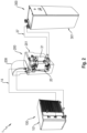
- Fig. 1 is a schematic diagram of a heat pump 1 according to the present disclosure.
- the heat pump 1 comprises a refrigerant circuit 10 for circulating a refrigerant and a heat medium circuit 30 for circulating a heat medium.
- the refrigerant circuit 10 has a compressor 11, a heat source heat exchanger 12, which is an evaporator in the present embodiment, an expansion valve 13, and an intermediate heat exchanger 20, which is a condenser in the present embodiment.
- the heat medium circuit 30 has a pump 36, the intermediate heat exchanger 20 and, optionally and as shown in Fig. 1 , a gas-liquid separator 31.
- the heat medium in the heat medium circuit 30 is circulated by means of the pump 36.
- a usage-side heat exchanger of the heat pump 1, which may be a radiator or a floor heater or the like, is not shown.
- the compressor 11, the heat source heat exchanger 12, and the expansion valve 13 form part of an outdoor unit 100 comprising an outdoor unit casing 101 accommodating the compressor 11, the heat source heat exchanger 12, and the expansion valve 13.
- the outdoor unit 100 is located outdoors.
- the intermediate heat exchanger 20, the gas-liquid separator 31, and the pump 36 are located indoors in the embodiment shown in Fig. 1 .
- the heat pump 1 comprises an indoor unit 300 comprising an indoor unit casing 301 housing at least the pump 36.
- the heat pump 1 further comprises a heat exchanger unit 200 comprising a container 201 housing the intermediate heat exchanger 20 and, optionally, the gas-liquid separator 31.
- the outdoor unit 100 on the one hand, and the indoor unit 300 and the heat exchanger unit 200 on the other hand are separated by a wall of a building or the like.
- the heat source heat exchanger 12, the compressor 11, the expansion valve 13, and the intermediate heat exchanger 20 are connected with each other via a refrigerant piping 14.
- the intermediate heat exchanger 20, the gas-liquid separator 31, and the pump 36 are connected with each other via a heat medium piping 37.
- the container 201 of the heat exchanger unit 200 housing the intermediate heat exchanger 20 is separate from the indoor unit casing 301 and the outdoor unit casing 101 and located outside of the indoor unit casing 301 and the outdoor unit casing 101, in case of refrigerant leakage at or in the intermediate heat exchanger 20, the leaked refrigerant is kept even further away from an indoor unit space or an outdoor unit space, in which potential ignition sources, such as electronic components, of the heat pump 1 are located, as opposed to a configuration in which a container housing the intermediate heat exchanger is located inside the indoor unit or outdoor unit of the heat pump. This leads to an improved safety of the heat pump 1.
- the heat pump 1 is a split-configuration heat pump 1, in which the heat source heat exchanger 12, the expansion valve 13, and the compressor 11 form part of the outdoor unit 100 of the heat pump 1 and are arranged together in an outdoor unit casing 101, while the intermediate heat exchanger 20 is located indoors. Since the container 201 of the heat exchanger unit 200 housing the intermediate heat exchanger 20 is located outside of the indoor unit casing 301, the refrigerant piping 14 connecting the components of the outdoor unit 100 with the intermediate heat exchanger 20 can be kept shorter, as opposed to a configuration in which a container housing the intermediate heat exchanger is located inside the indoor unit. As a result, the amount of refrigerant in the heat pump 1 can be reduced, thereby making the heat pump 1 cheaper.
- Fig. 2 is a schematic perspective view of an embodiment of the heat pump 1 of Fig. 1 .
- Both the outdoor unit casing 101 of the outdoor unit 100 and the indoor unit casing 301 of the indoor unit 300 have substantially cuboid shapes.
- the container 201 and the first duct 208 are depicted transparent for visibility of the components housed therein.
- the container 201 of the heat exchanger unit 200 has a box shape, which will be described in more detail below.
- the container 201 comprises a first duct 208, which will be described in more detail below.
- part of the refrigerant piping 14 is located within the first duct 208.
- the container 201 houses the intermediate heat exchanger 20 and the gas-liquid separator 31.
- the heat medium piping 37 enters the container 201 at one and the same outer wall of the container 201.
- the container 201 of the heat exchanger unit 200 is spaced apart from the indoor unit casing 301 of the indoor unit 300 and from the outdoor unit casing 101 of the outdoor unit 100.
- the heat exchanger unit 200 can be disposed at any desired location, independently from the outdoor unit casing 101 or the indoor unit casing 301, which leads to a high flexibility of the heat pump 1.
- Fig. 3 is a perspective view of an embodiment of an indoor unit 300 of the heat pump 1 of Fig. 1 .
- the indoor unit 300 has an indoor unit casing 301.
- the indoor unit 300 comprises a tank chamber part 302 and a machine chamber part 303.
- the machine chamber part 303 is disposed on top of the tank chamber part 302.
- the tank chamber part 302 and the machine chamber part 303 are integrally formed, so that at least one outer wall of the indoor unit casing 301 covers both the tank chamber part 302 and the machine chamber part 303.
- Fig. 4 is a schematic perspective view of a part of the indoor unit 300 of Fig. 3 with a heat exchanger unit 200.
- the tank chamber part 302 accommodates a hot water tank 3021.
- the heat medium circuit 30 further comprises a coil 3022 immersed in water contained in the hot water tank 3021 for exchanging heat with the water.
- the water in the hot water tank 3021 may be domestic water.
- the machine chamber part 303 accommodates the pump 36 of the heat medium circuit 30. Further components of the machine chamber part 303, such as electronic components, are omitted for easier illustration.
- the container 201 of the heat exchanger unit 200 is attached to the machine chamber part 303 of the indoor unit casing.
- the heat exchanger unit 200 can be considered as a "backpack" of the indoor unit 300.
- Fig. 5 is a perspective view of an embodiment of a heat exchanger unit 200 of the heat pump 1 of Fig. 1 .
- the container 201 and the first duct 208 are depicted transparent for visibility of the components housed therein.
- the (optional) gas-liquid separator 31 is disposed on the other side of the intermediate heat exchanger 20.
- the heat medium piping 37 penetrates the container 201 through the bottom wall of the container 201.
- the gas-liquid separator 31 constitutes a safety device as a safety measure against refrigerant leakage into the heat medium circuit 30, which is accommodated inside the container 201 of the heat exchanger unit 200, together with the intermediate heat exchanger 20.
- the intermediate heat exchanger 20 may be a double-walled plate heat exchanger, which constitutes a (further) safety device.
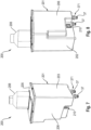
- Fig. 6 is a perspective view of the intermediate heat exchanger 20 and the gas-liquid separator 31 of the heat exchanger unit 200 of Fig. 5 .
- the gas-liquid separator 31 further comprises a gas purge valve 313.
- the gas purge valve 313 is provided for releasing gas, which accumulates in the gas-liquid separator 31, to the outside of the gas-liquid separator 31 in a controlled manner.
- the gas purge valve 313 is provided at the gas-liquid separator 31 at an upper side of the gas-liquid separator 31.
- Figs. 7, 8 , 9, and 10 are perspective views of the heat exchanger unit 200 of Fig. 5 from different directions, i.e., from different perspectives.
- the container 201 has a box shape with a first side wall 202 and a second side wall 203, opposing the first side wall 202, a rear wall 204 extending between the first side wall 202 and the second side wall 203, a top wall 205 being connected to upper ends of the first side wall 202, the second side wall 203, and the rear wall 204, a front wall 206 opposing the rear wall 204, and a bottom wall 207 opposing the top wall 205.
- the rear wall 204 of the container 201 is closer to the outdoor unit 100 than the front wall 206, meaning that the rear wall 204 is directly opposite to an inner side of a wall of a building or the like.
- a refrigerant pipe connection point 141 where the refrigerant piping 14 enters the container 201 is located at the top wall 205 of the container 201.
- the refrigerant pipe connection point 141 may as well be located at the rear wall 204, the first side wall 202, the second side wall 203, or the bottom wall 207 of the container 201.
- a heat medium pipe connection point 371 where the heat medium piping 37 enters the container 201 is located at the bottom wall 207 of the container 201.
- the heat medium pipe connection point 371 may as well be located at the front wall 206, the first side wall 202, the second side wall 202, or the top wall 205 of the container 201.
- a first duct 208 is provided at the container 201.
- the first duct 208 is provided at the top wall 205 of the container 201.
- the first duct 208 allows the inside of the container 201 to be in communication with outdoors, outdoors being where the outdoor unit 100 is located.
- the refrigerant pipe connection point 141 is located within the first duct 208.
- Fig. 11 is a schematic diagram of a part of an embodiment of the heat pump 1 of Fig. 1 .
- the first duct 208 is arranged at an upper portion of the container 201.
- An air intake opening 210 is provided at the container 201, in the present embodiment, at a lower portion of the container 201.
- the air intake opening 210 allows the inside of the container 201 to be in communication with indoors, indoors being where the indoor unit 300 is located.
- a fan 211 is arranged at an outdoor end of the first duct 208.
- the fan 211 is configured to generate an airflow inside the container 201 from the air intake opening 210 to outdoors through the first duct 208.
- an airflow is forcefully created within the container 201, thereby creating a forced ventilation of the container 201, as opposed to a natural ventilation of the container 201, and discharge of the leaked refrigerant to outdoors.
- a refrigerant leak detector 212 is provided inside the container 201. Operation of the fan 211 is dependent on a refrigerant leak detector signal. Operation of the fan 211 is started when the refrigerant leak detector 212 detects refrigerant inside the container 201, for example, when the refrigerant amount inside the container 201 is higher than a predetermined refrigerant amount value. In this case, the refrigerant leak detector 212 outputs a refrigerant leak detector signal.
- the container 201 of the heat exchanger unit 200 is mounted indoors to a floor of a building at a wall of the building.
- Fig. 12 is a schematic diagram of a part of an embodiment of the heat pump 1 of Fig. 1 .
- the first duct 208 is arranged at an upper portion of the container 201.
- a second duct 209 is provided at a lower portion of the container 201, the second duct 209 allowing the inside of the container 201 to be in communication with outdoors.
- first duct 208 and a second duct 209 at the container 201, wherein both the first duct 208 and the second duct 209 allow the inside of the container 201 to be in communication with outdoors
- natural ventilation of the container 201 is enabled, thereby discharging leaked refrigerant to outdoors.
- air can enter the container 201 through the first duct 208 and leave the container 201 through the second duct 209, thereby creating natural ventilation of the container and discharge of the leaked refrigerant to outdoors.
- the inside of the container 201 may be hermetically sealed from the outside of the container 201 to further improve safety of the heat pump 1.
- the container 201 of the heat exchanger unit 200 is mounted indoors to a wall of a building.
Landscapes
- Engineering & Computer Science (AREA)
- Chemical & Material Sciences (AREA)
- Combustion & Propulsion (AREA)
- Mechanical Engineering (AREA)
- General Engineering & Computer Science (AREA)
- Physics & Mathematics (AREA)
- Thermal Sciences (AREA)
- Other Air-Conditioning Systems (AREA)
Abstract
Description
- The present disclosure relates to a heat pump and, more particularly, to a separate configuration of an intermediate heat exchanger of the heat pump.
- A heat pump typically includes a refrigerant circuit, in which a refrigerant is circulated, and a heat medium circuit, in which a heat medium is circulated. The refrigerant circuit is configured so that the refrigerant takes up heat from the outdoors external environment by means of a heat source heat exchanger. Heat is then transferred to the heat medium in the heat medium circuit via an intermediate heat exchanger. Finally, heat is transferred to a usage-side heat exchanger, such as a radiator or floor heater. As such, heat is transported from outdoors to indoors, such as to an inside of a building.
- Development of heat pumps is facing a variety of challenges due to environmental and technical requirements. On the one hand, heat pumps should work as efficient as possible. On the other hand, the refrigerant used in the heat pumps should avoid any environmental risks, such as ozone depletion or the potential to contribute to global warming.
- To address these requirements, it has been proposed to use propane as refrigerant (R290) in heat pumps. This refrigerant has a good efficiency, while being environmentally friendly. However, propane is also not completely risk-free as it is flammable, thereby leading to the risk of fire.
- In order to minimize this risk, several legal regulations have been made and international standards have been set up, for example, regarding the maximum amount of refrigerant used in a heat pump system or the required dispersion height of potentially leaking refrigerant inside heat pump systems. Examples of such standards are the series of standards EN 378 or the standards IEC 60335-1 and IEC 60335-2-40.
- Besides these regulations, certain safety measures are used in heat pumps in order to avoid harm to persons in case of refrigerant leakage. One such safety measure is described in
EP 3 598 039 A1 . A container isolated from the interior space of the indoor unit of the heat pump is arranged inside the casing of the indoor unit. The container accommodates a load side heat exchanger (or intermediate heat exchanger). In case of refrigerant leakage at or in the load side heat exchanger, the leaked refrigerant is blocked by the container from entering the indoor unit space, in which potential ignition sources, such as electronic components, of the indoor unit of the heat pump are located. - However, even if a container accommodating the load side heat exchanger is provided inside the casing of the indoor unit, leaking refrigerant may still come into contact with potential ignition sources of the heat pump inside the indoor unit in case the container has a leak.
- Taking the aforesaid into account, it is an object of the present disclosure to provide a heat pump having an improved safety.
- This object is solved by a heat pump as defined in claim 1. Optional features and preferred embodiments of the heat pump are defined in the dependent claims.
- According to a first aspect, a heat pump comprises a refrigerant circuit for circulating a refrigerant comprising a compressor, a heat source heat exchanger, an expansion valve, and an intermediate heat exchanger, a heat medium circuit for circulating a heat medium comprising a pump and the intermediate heat exchanger, an outdoor unit comprising an outdoor unit casing housing at least the heat source heat exchanger, the compressor, and the expansion valve, an indoor unit comprising an indoor unit casing housing at least the pump, and a heat exchanger unit comprising a container housing the intermediate heat exchanger. The heat source heat exchanger, the compressor, the expansion valve, and the intermediate heat exchanger are connected with each other via a refrigerant piping, and the intermediate heat exchanger and the pump are connected with each other via a heat medium piping. The container of the heat exchanger unit is separate from the indoor unit casing and the outdoor unit casing and located outside of the indoor unit casing and the outdoor unit casing.
- Since the container of the heat exchanger unit housing the intermediate heat exchanger is separate from the indoor unit casing and the outdoor unit casing and located outside of the indoor unit casing and the outdoor unit casing, in case of refrigerant leakage at or in the intermediate heat exchanger, the leaked refrigerant is kept even further away from an indoor unit space or an outdoor unit space, in which potential ignition sources, such as electronic components, of the heat pump are located, as opposed to a configuration in which a container housing the intermediate heat exchanger is located inside the indoor unit or outdoor unit of the heat pump. This leads to an improved safety of the heat pump.
- Moreover, in case the heat pump is a split-configuration heat pump, in which the heat source heat exchanger, the expansion valve, and the compressor form part of an outdoor unit of the heat pump and are arranged together in an outdoor unit casing, while the intermediate heat exchanger is located indoors, since the container of the heat exchanger unit housing the intermediate heat exchanger is located outside of the indoor unit casing, the refrigerant piping connecting the components of the outdoor unit with the intermediate heat exchanger can be kept shorter, as opposed to a configuration in which a container housing the intermediate heat exchanger is located inside the indoor unit. As a result, the amount of refrigerant in the heat pump can be reduced, thereby making the heat pump cheaper.
- The refrigerant may include propane. The refrigerant may be R290. Furthermore, the refrigerant may be R32.
- The heat source heat exchanger may be an evaporator, in which the refrigerant exchanges heat with outside air, for example.
- The intermediate heat exchanger may be a condenser of the refrigerant circuit. The term "intermediate" may indicate that the intermediate heat exchanger is a heat exchanger between the heat source heat exchanger of the refrigerant circuit and the usage-side heat exchanger, which may be installed indoors, in a room of a building, and which may be a radiator or a floor heater or the like.
- The intermediate heat exchanger may be a plate heat exchanger. The intermediate heat exchanger may have a generally cuboid or box-like shape.
- The heat medium circuit may include water as heat medium.
- The pump may also be designated as a heat medium pump. The pump is generally configured to circulate the heat medium in the heat medium circuit.
- The outdoor unit is generally located outdoors, i.e., outside of a building or the like.
- The outdoor unit casing of the outdoor unit may comprise a machine chamber and an air chamber. The machine chamber may house the compressor and the expansion valve, as well as electronic components of the heat pump. The air chamber may house the heat source heat exchanger, a blower fan, and a bell mouth.
- The outdoor unit casing may have a cuboid or box-like shape, for example, comprising six outer walls, for example, two side walls, a front wall, a rear wall, a top wall, and a bottom wall, when considering the outdoor unit casing in an installed state, i.e., when the outdoor unit casing is installed at a building or the like.
- The indoor unit is generally located indoors, i.e., inside a building or the like. The inside of a building may generally be separated from the outside of the building by walls.
- The indoor unit casing may have a cuboid or box-like shape, for example, comprising six outer walls. Alternatively, the indoor unit casing may have a substantially cylindrical shape, for example, an elongated cylindrical shape. Alternatively, the indoor unit casing may have a part that has a substantially cylindrical shape, and a part of that has a cuboid or box-like shape.
- Herein, the term "substantially" may be used to designate a shape, a direction, an angle, or a positional relationship, or the like not only including the precise shape, direction, value of the angle, or positional relationship, but also small variations of that shape or around that direction, value of the angle, or positional relationship, such as 5%, for example, in case of a given value.
- The heat exchanger unit comprising the container housing the intermediate heat exchanger may be considered as a separate unit, with respect to the outdoor unit and the indoor unit of the heat pump, or may be considered as belonging to the outdoor unit or the indoor unit. The heat exchanger unit and, thus, the container may be located outdoors or indoors.
- The container housing the intermediate heat exchanger may have a substantially cuboid shape or box shape, for example, comprising six outer walls. The container may have a shape that conforms to the outer shape of the intermediate heat exchanger and, if applicable, to other components housed in the container, such as a gas-liquid separator.
- The container may be made of a plastic material, such as acrylonitrile styrene acrylate or similar.
- In case the heat exchanger unit and, thus, the container is located outdoors, part of the heat medium piping may be located outdoors. In this case, the heat medium piping may comprise measures for avoiding freezing of the heat medium, especially in case the heat medium is water. For example, the heat medium piping may comprise a heat insulation material around the part of the heat medium piping that is located outdoors.
- In case the heat exchanger unit and, thus, the container is located indoors, part of the refrigerant piping may be located indoors. In this case, the refrigerant piping may comprise measures for avoiding dissipation of heat from the refrigerant piping to surrounding air. For example, the refrigerant piping may comprise a heat insulation material around the refrigerant piping. The refrigerant piping may also comprise a safety measure for a case of a leaking refrigerant pipe, such as a double-walled refrigerant piping or a sheath around the refrigerant piping. The heat insulation material may be provided in combination with the sheath.
- In general, in case the heat exchanger unit is located outdoors, the refrigerant piping can be kept shorter and the refrigerant amount can be reduced, thereby making the heat pump cheaper, as opposed to a case in which the heat exchanger unit is located indoors. Specifically, the closer the container of the heat exchanger unit is located at the outdoor unit casing, the shorter the refrigerant piping. Moreover, since the heat exchanger unit is located outdoors, leaking refrigerant, such as propane, dilutes in air, thereby reducing the risk of fire. On the other hand, in case the heat exchanger unit is located indoors, the heat medium piping is completely located indoors and only the refrigerant piping is located outdoors. In this case, a greater difference in height is possible between the location of the outdoor unit and a point where the refrigerant piping enters the inside of a building or the like.
- The feature that the container is separate from the indoor unit casing and the outdoor unit casing may include that the container is independent from the indoor unit casing and the outdoor unit casing. For example, the container may be an independent entity, wherein none of the outer walls of the container form part of an outer wall of the indoor unit casing or the outdoor unit casing. For example, the container may be independently movable or arrangeable with respect to the outdoor unit casing and the indoor unit casing.
- According to a second aspect, the container of the heat exchanger unit may be spaced apart from the indoor unit casing and the outdoor unit casing.
- The feature that the container of the heat exchanger unit is spaced apart from the indoor unit casing and the outdoor unit casing may mean that the container is neither attached to the indoor unit casing nor to the outdoor unit casing.
- For example, the container may be spaced apart from the indoor unit casing so that a horizontal distance between the container and the indoor unit casing may be up to and including 25 m, as seen in a horizontal direction with respect to a building at which the heat pump is installed. Likewise, the container may be spaced apart from the outdoor unit casing so that a horizontal distance between the container and the outdoor unit casing may be up to and including 50 m, as seen in the horizontal direction. Moreover, the container may be spaced apart from the outdoor unit casing so that a vertical distance between the container and the outdoor unit casing may be up to and including 30 m, as seen in the vertical direction with respect to a building.
- With this configuration, in case the container of the heat exchanger unit is located indoors, it is possible to arrange the container of the heat exchanger unit close to a wall of a building or the like, while the indoor unit may be located elsewhere indoors, including a location far away from the wall of the building through which the refrigerant piping enters the building, thereby keeping the refrigerant piping between the components of the outdoor unit and the components of the heat exchanger unit as short as possible. Thereby, the amount of refrigerant in the heat pump can be reduced, which leads to a cheaper heat pump. This is in contrast to a case in that the indoor unit is located apart from the wall of the building, and the container is arranged inside the indoor unit casing. In such case, a long refrigerant pipe is needed to connect the indoor unit with the outdoor unit, thereby making it necessary to charge a large amount of refrigerant in the heat pump.
- Moreover, with this configuration, the heat exchanger unit can be disposed at any desired location, independently from the outdoor unit casing or the indoor unit casing, which leads to a high flexibility of the heat pump.
- According to a third aspect, the heat pump may further comprise a hot water tank, wherein the heat medium circuit may further comprise a coil immersed in water contained in the hot water tank for exchanging heat with the water, wherein the indoor unit may comprise a tank chamber part accommodating the hot water tank and the coil, and a machine chamber part accommodating at least the pump, wherein the machine chamber part may be disposed on top of the tank chamber part, wherein the container of the heat exchanger unit may be attached to the machine chamber part of the indoor unit casing.
- The hot water tank and the coil may be a hot water tank and a coil as known from heat pumps in the art.
- The water contained in the hot water tank may be domestic water, which is circulated through a radiator or a floor heater of a building or the like.
- The coil may be made of metal so as to promote heat exchange between the water contained in the hot water tank and the heat medium contained in the coil.
- The feature that the machine chamber part is disposed on top of the tank chamber part may refer to the up-down direction when considering the heat pump in an installed state, i.e., when the heat pump is installed at a building or the like.
- The tank chamber part and the machine chamber part may be separated from one another, for example, by a partition plate. The tank chamber part and the machine chamber part may each comprise an individual casing, so that the casing of the tank chamber part and the casing of the machine chamber part together form the indoor unit casing. Alternatively, the tank chamber part and the machine chamber part may be integrally formed, so that at least one outer wall of the indoor unit casing covers both the tank chamber part and the machine chamber part.
- The feature that the container of the heat exchanger unit is attached to the machine chamber part of the indoor unit casing may mean that the whole container or a majority of the container is attached to the machine chamber part. The term "majority" may be understood as more than 50% of the container. More than 50% may relate to the outer dimension of the container, as seen in the up-down direction.
- With this configuration, a compact design of the indoor unit with the heat exchanger unit can be provided, while still achieving an improved safety of the heat pump.
- According to a fourth aspect, the heat medium circuit may further comprise a safety device as a safety measure against refrigerant leakage into the heat medium circuit, wherein the safety device may be accommodated inside the container of the heat exchanger unit.
- The safety device may generally be understood as a device that is specifically configured to prevent leaking refrigerant at or in the intermediate heat exchanger to enter the heat medium circuit.
- In case the safety device is accommodated inside the container of the heat exchanger unit, the intermediate heat exchanger and the safety device are together accommodated inside the container. In this case, the container may have a shape that conforms to the outer shape of the configuration of the intermediate heat exchanger and the safety device.
- With this configuration, safety of the heat pump is further improved because the safety device constitutes an additional safety measure against leaking refrigerant.
- According to a fifth aspect, the safety device may be a gas-liquid separator.
- The gas-liquid separator generally has the following function. When refrigerant is leaked into the heat medium circuit, which usually occurs at the intermediate heat exchanger, the refrigerant, which is in the gaseous state, is separated from the liquid heat medium, usually water, by the gas-liquid separator and released or discharged to the outside of the heat pump in a controlled manner.
- The gas-liquid separator may be a conventional gas-liquid separator, as known in the art. In general, the gas-liquid separator may have a cylindrical, in particular, an elongated cylindrical, body, or may have a cuboid shape. As such, the gas-liquid separator may have a longitudinal axis, extending in a direction parallel to the direction of gravity when the gas-liquid separator is in an installed state, i.e., when the heat pump is in an installed state. The gas-liquid separator is generally configured to allow a gas-liquid mixture to separate therein. For this purpose, the gas-liquid separator needs to have a certain height to allow for the formation of a steady state in which the liquid heat medium is accumulated in a lower portion of the gas-liquid separator and the gaseous refrigerant is accumulated in an upper portion of the gas-liquid separator.
- With this configuration, safety of the heat pump is further improved. Moreover, a gas-liquid separator is usually cheaper than a double-walled plate heat exchanger, which is another type of safety device. Thus, safety of the heat pump can be improved, while keeping costs of the heat pump at a minimum.
- According to a sixth aspect, the gas-liquid separator may comprise a gas purge valve.
- The gas purge valve may generally be provided for releasing gas that accumulates in the gas-liquid separator to the outside of the gas-liquid separator in a controlled manner.
- The gas purge valve may be provided at the gas-liquid separator at an upper side of the gas-liquid separator.
- With this configuration, safety of the heat pump is further improved because the accumulated gas in the gas-liquid separator can be released in a controlled manner.
- According to a seventh aspect, the intermediate heat exchanger may be a double-walled plate heat exchanger being the safety device.
- In general, the double-walled plate heat exchanger has two walls separating the refrigerant from the heat medium. In case there is a leak in the first wall of the plate heat exchanger, the second wall prevents the refrigerant from entering through the leak into the heat medium circuit.
- With this configuration, safety of the heat pump is further improved. Moreover, a double-walled plate heat exchanger is generally smaller than the combination of a plate heat exchanger and a gas-liquid separator. Thus, safety of the heat pump can be improved, while keeping the outer dimension of the heat exchanger unit at a minimum.
- According to an eighth aspect, the container may have a box shape with a first side wall and a second side wall, opposing the first side wall, a rear wall extending between the first side wall and the second side wall, a top wall being connected to upper ends of the first side wall, the second side wall, and the rear wall, a front wall opposing the rear wall, and a bottom wall opposing the top wall, wherein the rear wall may be closer to the outdoor unit than the front wall, wherein a refrigerant pipe connection point where the refrigerant piping enters the container may be located at the top wall, the rear wall, the first side wall, the second side wall, or the bottom wall of the container.
- The box shape may be a cuboid, or substantially cuboid, shape, or a cube, or substantially cube, shape.
- The first side wall, the second side wall, the front wall, the top wall, the rear wall, and the bottom wall of the container may be outer surfaces of the container. The first side wall, the second side wall, the front wall, the top wall, the rear wall, and the bottom wall of the container may be flat surfaces or may be surfaces that include a step.
- The top wall may oppose the bottom wall in the up-down direction when considering the heat pump in an installed state, i.e., when the heat pump is installed at a building or the like.
- The feature that the rear wall is closer to the outdoor unit than the front wall may mean, in case the container is located indoors, that the rear wall is that wall of the container that directly opposes the wall of the building (or the like) through that the refrigerant piping enters the building.
- The refrigerant pipe connection point may be understood as a region at the container, or at a container wall, where the refrigerant piping enters or penetrates the container. The refrigerant pipe connection point may also be designated as a refrigerant pipe connection location.
- The refrigerant pipe connection point may include two penetration points of the refrigerant piping, namely, a first penetration point for a refrigerant pipe through that the refrigerant flows into the intermediate heat exchanger, and a second penetration point for a refrigerant pipe through that the refrigerant flows out from the intermediate heat exchanger.
- With this configuration, the refrigerant piping can be kept as short as possible, thereby reducing overall costs of the heat pump.
- According to a ninth aspect, a heat medium pipe connection point where the heat medium piping enters the container may be located at the front wall, the bottom wall, the first side wall, the second side wall, or the top wall of the container.
- The heat medium pipe connection point may be understood as a region at the container, or at a container wall, where the heat medium piping enters or penetrates the container. The heat medium pipe connection point may also be designated as a heat medium pipe connection location.
- The heat medium pipe connection point may include two penetration points of the heat medium piping, namely, a first penetration point for a heat medium pipe through that the heat medium flows into the intermediate heat exchanger, and a second penetration point for a heat medium pipe through that the heat medium flows out from the intermediate heat exchanger.
- With this configuration, the heat medium piping can be kept as short as possible, thereby reducing overall costs of the heat pump.
- According to a tenth aspect, a first duct may be provided at the container, the first duct allowing the inside of the container to be in communication with outdoors, outdoors being where the outdoor unit is located, wherein the refrigerant pipe connection point may be located within the first duct.
- The first duct may be a tube-like or a pipe-like element. The first duct may be integrally formed with the container. Alternatively, the first duct may be a separate element, which is connected with the container, for example, using a sealing member.
- The first duct may have a circular, elliptical, and/or oval cross-section. The shape of the cross-section of the first duct may vary along a length of the first duct from the container towards outdoors.
- The duct may be made of a polyvinyl chloride or a metallic.
- The first duct may allow the inside of the container to be in communication with outdoors by the first duct penetrating a wall of a building in case the container is located indoors, i.e., inside a building or the like. In this case, a hole that has approximately the same dimension than an outer dimension of the first duct needs to be provided in the wall. The location at the wall where the first duct penetrates the wall may be sealed, for example, using a sealing that blocks air and/or refrigerant.
- Since the refrigerant pipe connection point may be located within the first duct, it is not necessary to provide further holes in a wall of a building for guiding the refrigerant piping from outdoors to indoors. Moreover, safety is improved, in case of refrigerant leaking from the refrigerant piping.
- With this configuration, safety of the heat pump is further improved. This is because in case of a refrigerant leakage at or in the intermediate heat exchanger, the leaked refrigerant accumulates in the container and can, via the first duct, escape from the container to outdoors. For example, in case the container is located indoors, flammable refrigerant, such as propane, can thereby be led to outdoors, thereby reducing the risk of fire inside a building or the like. It is also conceivable, in order to further improve safety of the heat pump, that leaked refrigerant is pumped out of the container via the first duct, for example, by a professional maintenance worker.
- According to an eleventh aspect, the first duct may be arranged at an upper portion of the container, wherein a second duct may be provided at a lower portion of the container, the second duct allowing the inside of the container to be in communication with outdoors.
- The second duct may have the same configuration and the same features as the first duct.
- The upper portion and the lower portion of the container may be an upper portion and a lower portion as seen in the up-down direction, when the container is in an installed state, i.e., when the heat pump is in an installed state.
- With this configuration, safety of the heat pump is further improved. In particular, by providing a first duct and a second duct at the container, wherein both the first duct and the second duct allow the inside of the container to be in communication with outdoors, natural ventilation of the container is enabled. Natural ventilation means that no additional means, such as pumping, need to be applied to guide leaked refrigerant, which accumulates in the container, to outside. This is because outside air can enter the container through one of the ducts, for example, through the first duct, and leave the container through the other one of the ducts, for example, through the second duct, thereby creating natural ventilation of the container and discharge of the leaked refrigerant to outdoors.
- According to a twelfth aspect, the inside of the container may be hermetically sealed from the outside of the container.
- In this context, hermetically sealed may mean that neither air nor refrigerant can enter or escape through the container, including any sealings used between different parts of the container, for example, in case the container includes a lid or in case the first duct and/or the second duct are not integrally formed with the container.
- With this configuration, safety of the heat pump against refrigerant leakage is further improved.
- According to a thirteenth aspect, the first duct may be arranged at an upper portion of the container, wherein an air intake opening may be provided at the container, the air intake opening allowing the inside of the container to be in communication with indoors, indoors being where the indoor unit is located, wherein a fan may be arranged at an outdoor end of the first duct, the fan being configured to generate an airflow inside the container from the air intake opening to outdoors through the first duct.
- In this configuration, the container may be located indoors, indoors meaning an indoor space of a building or the like where the indoor unit is located.
- The air intake opening may be a hole provided in at least one of the outer walls of the container. The air intake opening may be provided with a one-way valve or a check valve, for example, so as to only allow a passage through the air intake opening from the outside of the container, i.e., from indoors (indoor space of a building), to the inside of the container, while blocking a passage through the air intake opening from the inside of the container to the outside of the container.
- The air intake opening may be provided at a lower portion of the container, so as to promote an airflow through the entire box.
- The outdoor end of the first duct may be the one end of the first duct penetrating through a wall of a building or the like, while the other end of the first duct is connected, for example, integrally connected, with the container.
- The fan may generally be configured to blow the gas in the container to outdoors, thereby creating a negative pressure in the container, which leads to gas from indoors being sucked into the container via the air intake opening, thereby leading to an airflow through the container from the air intake opening to the outdoor end of the first duct.
- With this configuration, safety of the heat pump is further improved. In particular, by operating the fan, an airflow is forcefully created within the container, thereby creating a forced ventilation of the container, as opposed to a natural ventilation of the container, and discharge of the leaked refrigerant to outdoors.
- According to a fourteenth aspect, a refrigerant leak detector may be provided inside the container, wherein operation of the fan may be dependent on a refrigerant leak detector signal.
- For example, the refrigerant leak detector may be an optical detector configured to detect refrigerant, for example, leaked refrigerant, inside the container.
- Operation of the fan may be started when the refrigerant leak detector detects refrigerant inside the container, for example, when the refrigerant amount inside the container is higher than a predetermined refrigerant amount value. In this case, the refrigerant leak detector may output a refrigerant leak detector signal.
- A control unit may be provided for controlling the refrigerant leak detector and the fan and for allowing communication between the refrigerant leak detector and the fan.
- With this configuration, operation of the fan does not need to be performed continuously, but only in case leaked refrigerant is detected. This saves electric power, thereby making the heat pump more efficient.
- According to a fifteenth aspect, the container of the heat exchanger unit may be configured to be mounted to a wall of a building or to a floor of a building at a wall of the building.
- The container may be configured to be mounted to a wall of a building or to a floor of a building at a wall of the building either outdoors or indoors.
- In case the container is mounted indoors to a wall or to a floor at a wall of the building, a distance between the wall and the container may be up to and including 50 cm, preferably 30 cm, so as to keep the refrigerant piping as short as possible.
- For example, the container may comprise a mounting structure, holding the container, wherein the mounting structure is configured to be mounted to a wall of a building, for example, using screws.
- The container may be configured to be mounted to a floor of a building at a wall of the building by the container comprising stands, a pedestal, or a platform, on which the container stands. The stands, the pedestal, or the platform may be fixed to the floor using screws or the like.
- With this configuration, the container can be easily arranged at a wall of a building, and the refrigerant piping length can be kept short in case the container is located indoors.
- Further aspects of the present disclosure may be found in the following description of particular embodiments referring to the accompanying drawings.
-
-
Fig. 1 is a schematic diagram of a heat pump according to the present disclosure. -
Fig. 2 is a schematic perspective view of an embodiment of the heat pump ofFig. 1 . -
Fig. 3 is a perspective view of an embodiment of an indoor unit of the heat pump ofFig. 1 . -
Fig. 4 is a schematic perspective view of a part of the indoor unit ofFig. 3 with a heat exchanger unit. -
Fig. 5 is a perspective view of an embodiment of a heat exchanger unit of the heat pump ofFig. 1 . -
Fig. 6 is a perspective view of an intermediate heat exchanger and a gas-liquid separator of the heat exchanger unit ofFig. 5 . -
Fig. 7 is a perspective view of the heat exchanger unit ofFig. 5 . -
Fig. 8 is a perspective view of the heat exchanger unit ofFig. 7 from another direction. -
Fig. 9 is a perspective view of the heat exchanger unit ofFig. 7 from another direction. -
Fig. 10 is a perspective view of the heat exchanger unit ofFig. 7 from another direction. -
Fig. 11 is a schematic diagram of a part of an embodiment of the heat pump ofFig. 1 . -
Fig. 12 is a schematic diagram of a part of an embodiment of the heat pump ofFig. 1 . - Hereinafter, embodiments according to the disclosure will be described in detail with reference to the accompanying drawings in order to describe the disclosure using illustrative examples. Further modifications of certain individual features described in this context can be combined with other features of the described embodiments to form further embodiments of the disclosure.
- Throughout the drawings, the same reference numerals are used for the same or similar elements.
-
Fig. 1 is a schematic diagram of a heat pump 1 according to the present disclosure. The heat pump 1 comprises arefrigerant circuit 10 for circulating a refrigerant and aheat medium circuit 30 for circulating a heat medium. Therefrigerant circuit 10 has acompressor 11, a heatsource heat exchanger 12, which is an evaporator in the present embodiment, anexpansion valve 13, and anintermediate heat exchanger 20, which is a condenser in the present embodiment. Theheat medium circuit 30 has apump 36, theintermediate heat exchanger 20 and, optionally and as shown inFig. 1 , a gas-liquid separator 31. The heat medium in theheat medium circuit 30 is circulated by means of thepump 36. A usage-side heat exchanger of the heat pump 1, which may be a radiator or a floor heater or the like, is not shown. - In the embodiment shown in
Fig. 1 , thecompressor 11, the heatsource heat exchanger 12, and theexpansion valve 13 form part of anoutdoor unit 100 comprising anoutdoor unit casing 101 accommodating thecompressor 11, the heatsource heat exchanger 12, and theexpansion valve 13. Theoutdoor unit 100 is located outdoors. On the other hand, theintermediate heat exchanger 20, the gas-liquid separator 31, and thepump 36 are located indoors in the embodiment shown inFig. 1 . The heat pump 1 comprises anindoor unit 300 comprising anindoor unit casing 301 housing at least thepump 36. The heat pump 1 further comprises aheat exchanger unit 200 comprising acontainer 201 housing theintermediate heat exchanger 20 and, optionally, the gas-liquid separator 31. Theoutdoor unit 100 on the one hand, and theindoor unit 300 and theheat exchanger unit 200 on the other hand are separated by a wall of a building or the like. - The heat
source heat exchanger 12, thecompressor 11, theexpansion valve 13, and theintermediate heat exchanger 20 are connected with each other via arefrigerant piping 14. Theintermediate heat exchanger 20, the gas-liquid separator 31, and thepump 36 are connected with each other via aheat medium piping 37. - As indicated in
Fig. 1 , thecontainer 201 of theheat exchanger unit 200 is separate from theindoor unit casing 301 and theoutdoor unit casing 101 and located outside of theindoor unit casing 301 and theoutdoor unit casing 101. - Since the
container 201 of theheat exchanger unit 200 housing theintermediate heat exchanger 20 is separate from theindoor unit casing 301 and theoutdoor unit casing 101 and located outside of theindoor unit casing 301 and theoutdoor unit casing 101, in case of refrigerant leakage at or in theintermediate heat exchanger 20, the leaked refrigerant is kept even further away from an indoor unit space or an outdoor unit space, in which potential ignition sources, such as electronic components, of the heat pump 1 are located, as opposed to a configuration in which a container housing the intermediate heat exchanger is located inside the indoor unit or outdoor unit of the heat pump. This leads to an improved safety of the heat pump 1. - Moreover, in
Fig. 1 , the heat pump 1 is a split-configuration heat pump 1, in which the heatsource heat exchanger 12, theexpansion valve 13, and thecompressor 11 form part of theoutdoor unit 100 of the heat pump 1 and are arranged together in anoutdoor unit casing 101, while theintermediate heat exchanger 20 is located indoors. Since thecontainer 201 of theheat exchanger unit 200 housing theintermediate heat exchanger 20 is located outside of theindoor unit casing 301, therefrigerant piping 14 connecting the components of theoutdoor unit 100 with theintermediate heat exchanger 20 can be kept shorter, as opposed to a configuration in which a container housing the intermediate heat exchanger is located inside the indoor unit. As a result, the amount of refrigerant in the heat pump 1 can be reduced, thereby making the heat pump 1 cheaper. -
Fig. 2 is a schematic perspective view of an embodiment of the heat pump 1 ofFig. 1 . Both theoutdoor unit casing 101 of theoutdoor unit 100 and theindoor unit casing 301 of theindoor unit 300 have substantially cuboid shapes. - The
container 201 and thefirst duct 208 are depicted transparent for visibility of the components housed therein. Thecontainer 201 of theheat exchanger unit 200 has a box shape, which will be described in more detail below. Moreover, thecontainer 201 comprises afirst duct 208, which will be described in more detail below. As indicated inFig. 2 , part of therefrigerant piping 14 is located within thefirst duct 208. Thecontainer 201 houses theintermediate heat exchanger 20 and the gas-liquid separator 31. As indicated inFig. 2 , the heat medium piping 37 enters thecontainer 201 at one and the same outer wall of thecontainer 201. - In the embodiment shown in
Fig. 2 , thecontainer 201 of theheat exchanger unit 200 is spaced apart from theindoor unit casing 301 of theindoor unit 300 and from theoutdoor unit casing 101 of theoutdoor unit 100. - In
Fig. 2 , thecontainer 201 is intended to be located indoors. In this case, it is possible to arrange thecontainer 201 of theheat exchanger unit 200 close to a wall of a building or the like, while theindoor unit 300 may be located elsewhere indoors, including a location far away from the wall of the building through which therefrigerant piping 14 enters the building, thereby keeping therefrigerant piping 14 between the components of theoutdoor unit 100 and the components of theheat exchanger unit 200 as short as possible. Thereby, the amount of refrigerant in the heat pump 1 can be reduced, which leads to a cheaper heat pump 1. - Moreover, with this configuration, the
heat exchanger unit 200 can be disposed at any desired location, independently from theoutdoor unit casing 101 or theindoor unit casing 301, which leads to a high flexibility of the heat pump 1. -
Fig. 3 is a perspective view of an embodiment of anindoor unit 300 of the heat pump 1 ofFig. 1 . Theindoor unit 300 has anindoor unit casing 301. Theindoor unit 300 comprises atank chamber part 302 and amachine chamber part 303. Themachine chamber part 303 is disposed on top of thetank chamber part 302. In the embodiment shown inFig. 3 , thetank chamber part 302 and themachine chamber part 303 are integrally formed, so that at least one outer wall of theindoor unit casing 301 covers both thetank chamber part 302 and themachine chamber part 303. -
Fig. 4 is a schematic perspective view of a part of theindoor unit 300 ofFig. 3 with aheat exchanger unit 200. Thetank chamber part 302 accommodates ahot water tank 3021. Theheat medium circuit 30 further comprises acoil 3022 immersed in water contained in thehot water tank 3021 for exchanging heat with the water. The water in thehot water tank 3021 may be domestic water. - The
machine chamber part 303 accommodates thepump 36 of theheat medium circuit 30. Further components of themachine chamber part 303, such as electronic components, are omitted for easier illustration. - In the embodiment of
Fig. 4 , thecontainer 201 of theheat exchanger unit 200 is attached to themachine chamber part 303 of the indoor unit casing. In this embodiment, theheat exchanger unit 200 can be considered as a "backpack" of theindoor unit 300. - With this configuration, a compact design of the
indoor unit 300 with theheat exchanger unit 200 can be provided, while still achieving an improved safety of the heat pump 1. -
Fig. 5 is a perspective view of an embodiment of aheat exchanger unit 200 of the heat pump 1 ofFig. 1 . Thecontainer 201 and thefirst duct 208 are depicted transparent for visibility of the components housed therein. In contrast to theheat exchanger unit 200 shown inFig. 2 , the (optional) gas-liquid separator 31 is disposed on the other side of theintermediate heat exchanger 20. Moreover, instead of penetrating thecontainer 201 through a side wall of thecontainer 201, the heat medium piping 37 penetrates thecontainer 201 through the bottom wall of thecontainer 201. - The gas-
liquid separator 31 constitutes a safety device as a safety measure against refrigerant leakage into theheat medium circuit 30, which is accommodated inside thecontainer 201 of theheat exchanger unit 200, together with theintermediate heat exchanger 20. - In addition, or as an alternative, the
intermediate heat exchanger 20 may be a double-walled plate heat exchanger, which constitutes a (further) safety device. -
Fig. 6 is a perspective view of theintermediate heat exchanger 20 and the gas-liquid separator 31 of theheat exchanger unit 200 ofFig. 5 . As can be seen inFig. 6 , the gas-liquid separator 31 further comprises agas purge valve 313. Thegas purge valve 313 is provided for releasing gas, which accumulates in the gas-liquid separator 31, to the outside of the gas-liquid separator 31 in a controlled manner. In the embodiment shown inFig. 6 , thegas purge valve 313 is provided at the gas-liquid separator 31 at an upper side of the gas-liquid separator 31. -
Figs. 7, 8 ,9, and 10 are perspective views of theheat exchanger unit 200 ofFig. 5 from different directions, i.e., from different perspectives. Thecontainer 201 has a box shape with afirst side wall 202 and asecond side wall 203, opposing thefirst side wall 202, arear wall 204 extending between thefirst side wall 202 and thesecond side wall 203, atop wall 205 being connected to upper ends of thefirst side wall 202, thesecond side wall 203, and therear wall 204, afront wall 206 opposing therear wall 204, and abottom wall 207 opposing thetop wall 205. - In the heat pump 1, the
rear wall 204 of thecontainer 201 is closer to theoutdoor unit 100 than thefront wall 206, meaning that therear wall 204 is directly opposite to an inner side of a wall of a building or the like. - As can be seen in
Fig. 10 , a refrigerantpipe connection point 141 where therefrigerant piping 14 enters thecontainer 201 is located at thetop wall 205 of thecontainer 201. However, the refrigerantpipe connection point 141 may as well be located at therear wall 204, thefirst side wall 202, thesecond side wall 203, or thebottom wall 207 of thecontainer 201. - As shown in
Figs. 7, 8 , and9 , a heat mediumpipe connection point 371 where the heat medium piping 37 enters thecontainer 201 is located at thebottom wall 207 of thecontainer 201. However, the heat mediumpipe connection point 371 may as well be located at thefront wall 206, thefirst side wall 202, thesecond side wall 202, or thetop wall 205 of thecontainer 201. - Moreover, a
first duct 208 is provided at thecontainer 201. InFigs. 7, 8 ,9, and 10 , only a part of thefirst duct 208 is depicted. In the present embodiment, thefirst duct 208 is provided at thetop wall 205 of thecontainer 201. Thefirst duct 208 allows the inside of thecontainer 201 to be in communication with outdoors, outdoors being where theoutdoor unit 100 is located. As shown inFig. 10 , the refrigerantpipe connection point 141 is located within thefirst duct 208. -
Fig. 11 is a schematic diagram of a part of an embodiment of the heat pump 1 ofFig. 1 . Thefirst duct 208 is arranged at an upper portion of thecontainer 201. Anair intake opening 210 is provided at thecontainer 201, in the present embodiment, at a lower portion of thecontainer 201. Theair intake opening 210 allows the inside of thecontainer 201 to be in communication with indoors, indoors being where theindoor unit 300 is located. - A
fan 211 is arranged at an outdoor end of thefirst duct 208. Thefan 211 is configured to generate an airflow inside thecontainer 201 from theair intake opening 210 to outdoors through thefirst duct 208. By operating thefan 211, an airflow is forcefully created within thecontainer 201, thereby creating a forced ventilation of thecontainer 201, as opposed to a natural ventilation of thecontainer 201, and discharge of the leaked refrigerant to outdoors. - Moreover, a
refrigerant leak detector 212 is provided inside thecontainer 201. Operation of thefan 211 is dependent on a refrigerant leak detector signal. Operation of thefan 211 is started when therefrigerant leak detector 212 detects refrigerant inside thecontainer 201, for example, when the refrigerant amount inside thecontainer 201 is higher than a predetermined refrigerant amount value. In this case, therefrigerant leak detector 212 outputs a refrigerant leak detector signal. - In the embodiment shown in
Fig. 11 , thecontainer 201 of theheat exchanger unit 200 is mounted indoors to a floor of a building at a wall of the building. -
Fig. 12 is a schematic diagram of a part of an embodiment of the heat pump 1 ofFig. 1 . Thefirst duct 208 is arranged at an upper portion of thecontainer 201. Asecond duct 209 is provided at a lower portion of thecontainer 201, thesecond duct 209 allowing the inside of thecontainer 201 to be in communication with outdoors. - By providing the
first duct 208 and asecond duct 209 at thecontainer 201, wherein both thefirst duct 208 and thesecond duct 209 allow the inside of thecontainer 201 to be in communication with outdoors, natural ventilation of thecontainer 201 is enabled, thereby discharging leaked refrigerant to outdoors. For example, air can enter thecontainer 201 through thefirst duct 208 and leave thecontainer 201 through thesecond duct 209, thereby creating natural ventilation of the container and discharge of the leaked refrigerant to outdoors. - In this case, the inside of the
container 201 may be hermetically sealed from the outside of thecontainer 201 to further improve safety of the heat pump 1. - In the embodiment shown in
Fig. 12 , thecontainer 201 of theheat exchanger unit 200 is mounted indoors to a wall of a building. -
- 1
- Heat pump
- 10
- Refrigerant circuit
- 11
- Compressor
- 12
- Heat source heat exchanger
- 13
- Expansion valve
- 20
- Intermediate heat exchanger
- 30
- Heat medium circuit
- 36
- Pump
- 31
- Gas-liquid separator
- 100
- Outdoor unit
- 101
- Outdoor unit casing
- 300
- Indoor unit
- 301
- Indoor unit casing
- 200
- Heat exchanger unit
- 201
- Container
- 14
- Refrigerant piping
- 37
- Heat medium piping
- 302
- Tank chamber part
- 3021
- Hot water tank
- 3022
- Coil
- 303
- Machine chamber part
- 313
- Gas purge valve
- 202
- First side wall
- 203
- Second side wall
- 204
- Rear wall
- 205
- Top wall
- 206
- Front wall
- 207
- Bottom wall
- 141
- Refrigerant pipe connection point
- 371
- Heat medium pipe connection point
- 208
- First duct
- 209
- Second duct
- 210
- Air intake opening
- 211
- Fan
- 212
- Refrigerant leak detector
Claims (15)
- A heat pump (1), comprisinga refrigerant circuit (10) for circulating a refrigerant comprising a compressor (11), a heat source heat exchanger (12), an expansion valve (13), and an intermediate heat exchanger (20),a heat medium circuit (30) for circulating a heat medium comprising a pump (36) and the intermediate heat exchanger (20),an outdoor unit (100) comprising an outdoor unit casing (101) housing at least the heat source heat exchanger (12), the compressor (11), and the expansion valve (13),an indoor unit (300) comprising an indoor unit casing (301) housing at least the pump (36), anda heat exchanger unit (200) comprising a container (201) housing the intermediate heat exchanger (20),wherein the heat source heat exchanger (12), the compressor (11), the expansion valve (13), and the intermediate heat exchanger (20) are connected with each other via a refrigerant piping (14), and the intermediate heat exchanger (20) and the pump (36) are connected with each other via a heat medium piping (37),wherein the container (201) of the heat exchanger unit (200) is separate from the indoor unit casing (301) and the outdoor unit casing (101) and located outside of the indoor unit casing (301) and the outdoor unit casing (101).
- The heat pump (1) according to claim 1,
wherein the container (201) of the heat exchanger unit (200) is spaced apart from the indoor unit casing (301) and the outdoor unit casing (101). - The heat pump (1) according to claim 1,further comprising a hot water tank (3021), wherein the heat medium circuit (30) further comprises a coil (3022) immersed in water contained in the hot water tank (3021) for exchanging heat with the water,wherein the indoor unit (300) comprises
a tank chamber part (302) accommodating the hotwater tank (3021) and the coil (3022), and
a machine chamber part (303) accommodating at least the pump (36), the machine chamber part (303) being disposed on top of the tank chamber part (302),wherein the container (201) of the heat exchanger unit (200) is attached to the machine chamber part (303) of the indoor unit casing (301). - The heat pump (1) according to any one of claims 1 to 3,
wherein the heat medium circuit (30) further comprises a safety device as a safety measure against refrigerant leakage into the heat medium circuit (30), the safety device being accommodated inside the container (201) of the heat exchanger unit (200). - The heat pump (1) according to claim 4,
wherein the safety device is a gas-liquid separator (31) . - The heat pump (1) according to claim 5,
wherein the gas-liquid separator (31) comprises a gas purge valve (313). - The heat pump (1) according to any one of claims 4 to 6,
wherein the intermediate heat exchanger (20) is a double-walled plate heat exchanger being the safety device. - The heat pump (1) according to any one of the preceding claims,wherein the container (201) has a box shape with a first side wall (202) and a second side wall (203), opposing the first side wall (202), a rear wall (204) extending between the first side wall (202) and the second side wall (203), a top wall (205) being connected to upper ends of the first side wall (202), the second side wall (203), and the rear wall (204), a front wall (206) opposing the rear wall (204), and a bottom wall (207) opposing the top wall (205), the rear wall (204) being closer to the outdoor unit (100) than the front wall (206),wherein a refrigerant pipe connection point (141) where the refrigerant piping (14) enters the container (201) is located at the top wall (205), the rear wall (204), the first side wall (202), the second side wall (203), or the bottom wall (207) of the container (201).
- The heat pump (1) according to claim 8,
wherein a heat medium pipe connection point (371) where the heat medium piping (37) enters the container (201) is located at the front wall (206), the bottom wall (207), the first side wall (202), the second side wall (202), or the top wall (205) of the container (201). - The heat pump (1) according to claim 8 or 9,wherein a first duct (208) is provided at the container (201), the first duct (208) allowing the inside of the container (201) to be in communication with outdoors, outdoors being where the outdoor unit (100) is located,wherein the refrigerant pipe connection point (141) is located within the first duct (208).
- The heat pump (1) according to claim 10,wherein the first duct (208) is arranged at an upper portion of the container (201),wherein a second duct (209) is provided at a lower portion of the container (201),the second duct (209) allowing the inside of the container (201) to be in communication with outdoors.
- The heat pump (1) according to any one of the preceding claims,
wherein the inside of the container (201) is hermetically sealed from the outside of the container (201). - The heat pump (1) according to claim 10,wherein the first duct (208) is arranged at an upper portion of the container (201),wherein an air intake opening (210) is provided at the container (201), the air intake opening (210) allowing the inside of the container (201) to be in communication with indoors, indoors being where the indoor unit (300) is located,wherein a fan (211) is arranged at an outdoor end of the first duct (208), the fan (211) being configured to generate an airflow inside the container (201) from the air intake opening (210) to outdoors through the first duct (208).
- The heat pump (1) according to claim 13,wherein a refrigerant leak detector (212) is provided inside the container (201),wherein operation of the fan (211) is dependent on a refrigerant leak detector signal.
- The heat pump (1) according to any one of the preceding claims,
wherein the container (201) of the heat exchanger unit (200) is configured to be mounted to a wall of a building or to a floor of a building at a wall of the building.
Priority Applications (4)
| Application Number | Priority Date | Filing Date | Title |
|---|---|---|---|
| EP23175729.5A EP4467884A1 (en) | 2023-05-26 | 2023-05-26 | Heat pump |
| JP2025568722A JP2026517475A (en) | 2023-05-26 | 2024-05-23 | heat pump |
| PCT/EP2024/064245 WO2024245897A1 (en) | 2023-05-26 | 2024-05-23 | Heat pump |
| CN202480034010.9A CN121152945A (en) | 2023-05-26 | 2024-05-23 | heat pump |
Applications Claiming Priority (1)
| Application Number | Priority Date | Filing Date | Title |
|---|---|---|---|
| EP23175729.5A EP4467884A1 (en) | 2023-05-26 | 2023-05-26 | Heat pump |
Publications (1)
| Publication Number | Publication Date |
|---|---|
| EP4467884A1 true EP4467884A1 (en) | 2024-11-27 |
Family
ID=86605226
Family Applications (1)
| Application Number | Title | Priority Date | Filing Date |
|---|---|---|---|
| EP23175729.5A Pending EP4467884A1 (en) | 2023-05-26 | 2023-05-26 | Heat pump |
Country Status (1)
| Country | Link |
|---|---|
| EP (1) | EP4467884A1 (en) |
Citations (5)
| Publication number | Priority date | Publication date | Assignee | Title |
|---|---|---|---|---|
| US20110192189A1 (en) * | 2008-10-29 | 2011-08-11 | Mitsubishi Electric Corporation | Air-conditioning apparatus |
| US20130205824A1 (en) * | 2010-12-07 | 2013-08-15 | Mitsubishi Electric Corporation | Heat pump device |
| EP3199883A1 (en) * | 2014-09-25 | 2017-08-02 | Mitsubishi Electric Corporation | Heat pump apparatus |
| EP3598039A1 (en) | 2017-03-15 | 2020-01-22 | Mitsubishi Electric Corporation | Heat pump device and installation method therefor |
| US20210156575A1 (en) * | 2018-02-28 | 2021-05-27 | Mitsubishi Electric Corporation | Air-conditioning apparatus |
-
2023
- 2023-05-26 EP EP23175729.5A patent/EP4467884A1/en active Pending
Patent Citations (5)
| Publication number | Priority date | Publication date | Assignee | Title |
|---|---|---|---|---|
| US20110192189A1 (en) * | 2008-10-29 | 2011-08-11 | Mitsubishi Electric Corporation | Air-conditioning apparatus |
| US20130205824A1 (en) * | 2010-12-07 | 2013-08-15 | Mitsubishi Electric Corporation | Heat pump device |
| EP3199883A1 (en) * | 2014-09-25 | 2017-08-02 | Mitsubishi Electric Corporation | Heat pump apparatus |
| EP3598039A1 (en) | 2017-03-15 | 2020-01-22 | Mitsubishi Electric Corporation | Heat pump device and installation method therefor |
| US20210156575A1 (en) * | 2018-02-28 | 2021-05-27 | Mitsubishi Electric Corporation | Air-conditioning apparatus |
Similar Documents
| Publication | Publication Date | Title |
|---|---|---|
| CN114423999B (en) | Heat pumps and how to install them | |
| EP3998443A1 (en) | Indoor unit of refrigeration equipment | |
| JPWO2018216052A1 (en) | Unit equipment for refrigeration cycle equipment | |
| JP2005114244A (en) | Air conditioner outdoor unit | |
| JP2009085466A (en) | Outdoor unit of air conditioner | |
| WO2019030796A1 (en) | Indoor unit of air conditioning apparatus, air conditioning apparatus, and method for installing indoor unit of air conditioning apparatus | |
| EP3598038A1 (en) | Heat pump apparatus | |
| KR20240096255A (en) | Outdoor unit of airconditioner | |
| WO2024245897A1 (en) | Heat pump | |
| EP4467900A1 (en) | Indoor unit and heat pump | |
| US20250093051A1 (en) | Outdoor unit of air conditioner | |
| EP4467901A1 (en) | Heat pump | |
| JP7086269B2 (en) | Indoor unit | |
| JP6398373B2 (en) | Air conditioner floor-mounted indoor unit | |
| EP4279824A1 (en) | Air conditioner | |
| JP7841055B1 (en) | Outdoor unit and heat pump system equipped therewith | |
| EP4641099A1 (en) | Outdoor unit of air conditioner, and air conditioner having same | |
| JP6398372B2 (en) | Air conditioner floor-mounted indoor unit | |
| CN121002336A (en) | Indoor unit and heat pump | |
| EP4560207A1 (en) | Outdoor unit for a heat pump | |
| JP2022120822A (en) | Storage chamber | |
| JP2017083141A (en) | Air conditioner | |
| WO2026018320A1 (en) | Ventilation device, indoor unit, and air conditioner | |
| CN120641708A (en) | Air conditioner outdoor unit | |
| KR20240155690A (en) | Air conditioner |
Legal Events
| Date | Code | Title | Description |
|---|---|---|---|
| PUAI | Public reference made under article 153(3) epc to a published international application that has entered the european phase |
Free format text: ORIGINAL CODE: 0009012 |
|
| STAA | Information on the status of an ep patent application or granted ep patent |
Free format text: STATUS: THE APPLICATION HAS BEEN PUBLISHED |
|
| AK | Designated contracting states |
Kind code of ref document: A1 Designated state(s): AL AT BE BG CH CY CZ DE DK EE ES FI FR GB GR HR HU IE IS IT LI LT LU LV MC ME MK MT NL NO PL PT RO RS SE SI SK SM TR |
|
| STAA | Information on the status of an ep patent application or granted ep patent |
Free format text: STATUS: REQUEST FOR EXAMINATION WAS MADE |
|
| 17P | Request for examination filed |
Effective date: 20250321 |
|
| RIN1 | Information on inventor provided before grant (corrected) |
Inventor name: GARCIA LOPEZ, JOSE DANIEL Inventor name: DECAESTECKER, MICHIEL Inventor name: BALADAKIS-KOTTAS, KONSTANTINOS Inventor name: ISTANBULLU, ANIL |