EP4467875A1 - Device for combusting coke oven emission gases, method of combusting coke oven emission gases, and method of designing device for combusting coke oven emission gases - Google Patents
Device for combusting coke oven emission gases, method of combusting coke oven emission gases, and method of designing device for combusting coke oven emission gases Download PDFInfo
- Publication number
- EP4467875A1 EP4467875A1 EP22924071.8A EP22924071A EP4467875A1 EP 4467875 A1 EP4467875 A1 EP 4467875A1 EP 22924071 A EP22924071 A EP 22924071A EP 4467875 A1 EP4467875 A1 EP 4467875A1
- Authority
- EP
- European Patent Office
- Prior art keywords
- gas
- pipe
- combustion
- coke oven
- blow
- Prior art date
- Legal status (The legal status is an assumption and is not a legal conclusion. Google has not performed a legal analysis and makes no representation as to the accuracy of the status listed.)
- Pending
Links
Images




Classifications
-
- F—MECHANICAL ENGINEERING; LIGHTING; HEATING; WEAPONS; BLASTING
- F23—COMBUSTION APPARATUS; COMBUSTION PROCESSES
- F23G—CREMATION FURNACES; CONSUMING WASTE PRODUCTS BY COMBUSTION
- F23G7/00—Incinerators or other apparatus for consuming industrial waste, e.g. chemicals
- F23G7/06—Incinerators or other apparatus for consuming industrial waste, e.g. chemicals of waste gases or noxious gases, e.g. exhaust gases
- F23G7/08—Incinerators or other apparatus for consuming industrial waste, e.g. chemicals of waste gases or noxious gases, e.g. exhaust gases using flares, e.g. in stacks
-
- F—MECHANICAL ENGINEERING; LIGHTING; HEATING; WEAPONS; BLASTING
- F23—COMBUSTION APPARATUS; COMBUSTION PROCESSES
- F23G—CREMATION FURNACES; CONSUMING WASTE PRODUCTS BY COMBUSTION
- F23G2207/00—Control
- F23G2207/30—Oxidant supply
-
- F—MECHANICAL ENGINEERING; LIGHTING; HEATING; WEAPONS; BLASTING
- F23—COMBUSTION APPARATUS; COMBUSTION PROCESSES
- F23G—CREMATION FURNACES; CONSUMING WASTE PRODUCTS BY COMBUSTION
- F23G2209/00—Specific waste
- F23G2209/14—Gaseous waste or fumes
Definitions
- the present invention relates to a combustion apparatus for coke oven emission gas, a combustion method for coke oven emission gas, and a method of designing the combustion apparatus for coke oven emission gas, each capable of enhancing the complete combustion of the coke oven emission gas, and thus reducing the discharge amount of the coke oven emission gas in an incomplete combustion state.
- an emission bleeder is widely known as an apparatus for discharging coke oven gas.
- an emission bleeder 1 has a double-pipe structure including a hood 2 that communicates with the atmosphere at its opening located in the upper portion of the drawing, and a bleeder pipe 3 that is enveloped within an end of the hood 2 on the side opposite to the opening of the hood 2 and that communicates with the source of generation of coke oven gas.
- combustible gas 11G is fed into the bleeder pipe 3 by pressure, and resulting negative pressure allows oxygen-containing gas (e.g., air) to be drawn into the hood 2 through a gap 5 between the hood 2 and the bleeder pipe 3.
- oxygen-containing gas e.g., air
- the gases are mixed and are ignited by an ignition device 6, so that complete combustion of the combustible gas 11G can be achieved.
- an ignition device 6 so that complete combustion of the combustible gas 11G can be achieved.
- a sufficient amount of oxygen-containing gas (air) cannot be drawn into the inside of the hood 2 through the gap 5, making it difficult to achieve complete combustion of the coke oven gas 11G. Therefore, a large amount of the coke oven gas 11G is discharged into the atmosphere in an incomplete combustion state, which is problematic.
- Patent Literature 1 is cited as a document disclosing a technology related to such an emission bleeder. Specifically, Patent Literature 1 discloses adjusting the size, number, and spacing of air passages provided in a hood, for example, to adjust the amount of air to be drawn into the hood and thus improve combustion efficiency.
- Patent Literature 2 is cited as another document that also discloses a technology related to such an emission bleeder. Specifically, Patent Literature 2 discloses improving combustion efficiency by passing air through a bleeder pipe so that combustible gas can be drawn in through a gap between the bleeder pipe and a hood.
- Patent Literature 3 discloses a gas burner-type apparatus for increasing the amount of air in a combustion zone (facilitating the combustion of combustible gas in the atmosphere) that includes a venturi tube and a motive fluid feeding pipe.
- the apparatus includes a combustion zone that receives the combustible gas via a combustion gas feeding pipe.
- the end of the feeding pipe is surrounded by multiple devices that inject a motive fluid into the venturi tube located above the combustion zone.
- Patent Literature 4 discloses a flare gas burner for smokeless combustion of waste gas.
- the flare gas burner includes a device that discharges a high-pressure motive fluid from a manifold into a passage defined by the interior of a deflector and the exterior of a waste gas delivery pipe.
- Patent Literature 5 discloses an apparatus for enhancing combustion with a configuration in which high-pressure air is discharged in the form of a high-velocity jet from a nozzle mounted on a ring manifold surrounding a flare stack at a predetermined distance below a stack outlet, and in which the upper portion of the flare stack is surrounded by an outer shield that is provided with internal guide vanes at the top portion and perforated with air passages 52 at the bottom portion.
- Patent Literature 6 discloses a combustion emission pipe for combustion and emission of unrefined coke oven gas.
- the combustion emission pipe includes blow-in pipes that jet vapor through the gap between a bleeder pipe and a hood and through the inside of the bleeder pipe.
- Patent Literature 1 requires additional components or systems, for example, for controlling the amount of air to be drawn into the hood. This makes the configuration and operation of the apparatus complex, which is problematic. In particular, significant modifications to the hood of the emission bleeder are required.
- Patent Literature 2 has a drawback that requires modification of the entire apparatus to apply its technology to a typical conventional emission bleeder. Specifically, the gas flow is required to be different from the conventional gas flow, such as that air is drawn into the hood by passing the combustible gas through the bleeder pipe.
- Patent Literatures 3 through 6 Each of the technologies described in Patent Literatures 3 through 6 involves forcibly blowing another gaseous fluid into combustible gas, but does not define either the efficient blowing conditions or the design of the apparatus.
- the technology described in Patent Literature 6 involves jetting gas from the center of the bleeder pipe.
- the inventors believe that such a configuration has the disadvantage of requiring high modification costs without achieving sufficient combustion efficiency.
- the present invention has been made in view of the above circumstances, and an object of the present invention is to provide a combustion apparatus for coke oven emission gas, a combustion method for coke oven emission gas, and a method of designing the combustion apparatus for coke oven emission gas, each capable of improving combustion efficiency for combustible gas while reducing the modification cost for an emission bleeder that has been conventionally used.
- a combustion apparatus for coke oven emission gas according to the present invention that advantageously solves the above problems, includes
- the combustion apparatus for coke oven emission gas according to the present invention is considered to have more preferable solution means as follows:
- a method of designing a combustion apparatus for coke oven emission gas according to the present invention that advantageously solves the above problems includes, in designing a combustion apparatus for coke oven emission gas provided with
- the present invention can promote the complete combustion of coke oven emission gas and thus reduce the amount of emission of the coke oven emission gas in an incomplete combustion state without the need to significantly modify an emission bleeder.
- a coke oven 11 includes carbonization chambers 12 and combustion chambers 13 that are alternately arranged. In each combustion chamber 13, heat is generated by the combustion of combustion gas. In each carbonization chamber 12, coal is carbonized with the heat generated in the adjacent combustion chambers 13. During the carbonization process of coal, combustible gas called COG gas (hereinafter, C gas), which is a type of combustible gas, is generated.
- C gas combustible gas
- the C gas is composed mainly of H 2 , CO, and various other hydrocarbon gases, for example.
- FIG. 2 only shows two carbonization chambers 12 and two combustion chambers 13, but in practice, a large number of combinations of carbonization chambers 12 and combustion chambers 13 are provided toward the depth side of the drawing.
- Each of the carbonization chambers 12 has a riser pipe 14 and a dry main 15 at its upper portion.
- the riser pipe 14 collects C gas that has risen, and the dry main 15 aggregates the C gas sucked from the plurality of carbonization chambers 12 via the riser pipe 14.
- An emission bleeder 1 is connected to the dry main 15. The C gas generated in the plurality of carbonization chambers 12 passes through the riser pipe 14 and the dry main 15, and is then discharged to the atmosphere through the emission bleeder 1.
- a combustion apparatus for coke oven gas includes the emission bleeder 1 and a control means 7 for controlling a combustion-promoting gas.
- the emission bleeder 1 includes a hood 2, a bleeder pipe 3, and blow-in pipes 4.
- FIG. 1(a) shows an example in which the hood 2 is a single-wall cylindrical member
- FIG. 2(b) shows an example in which the hood is a double-wall cylindrical member
- the bleeder pipe 3 communicates with the dry main 15 of the coke oven 11, where C gas 11G is generated, at one end (not shown), which is an end face 3B located in the lower portion of the drawing, allowing the C gas 11G to pass through toward the hood 2.
- the C gas 11G flows from the lower portion toward the upper portion.
- the hood 2 discharges the C gas 11G, which has been fed from the bleeder pipe 3, to the atmosphere through one end 2A (the upper end) open to the atmosphere.
- the other end 3A of the bleeder pipe 3 is enveloped within the hood 2.
- the other end 2B (the lower end face) of the hood 2 is located at a position below the other end 3A (the upper end face) of the bleeder pipe 3 to thus form a region where the bleeder pipe 3 is enveloped within the hood 2.
- a gap 5 is formed between the inner wall of the hood 2 and the outer wall of the bleeder pipe 3.
- the inner wall of the hood 2 is provided with an ignition device 6 that first ignites the C gas 11G, which is the coke oven emission gas.
- the blow-in pipes 4 are provided, each of which can inject gas (hereinafter referred to as "combustion-promoting gas") in the inside of the hood 2 through the gap 5, which is formed between the bleeder pipe 3 and the hood 2.
- Each blow-in pipe 4 may be connected to a pump (not shown), for example, to feed a combustion-promoting gas by pressure.
- a flow of not only the combustion-promoting gas but also gas hereinafter referred to as "associated gas”
- associated gas such as air
- the combustion-promoting gas and the associated gas injected into the gap 5 rise along the outer wall of the bleeder pipe 3 and then are mixed with the coke oven emission gas (C gas 11G), which is fed from the inside of the bleeder pipe 3, inside of the hood 2, so that the gasses are stirred and mixed. After these gasses are stirred and mixed, they are ignited by the ignition device 6.
- the resulting gas discharged from the upper end of the hood 2 is mixed with the outside air and thus combusted so that a flame (not shown) is formed in an upward direction from the upper end face of the bleeder pipe 3.
- the mixed gas of the combustion-promoting gas fed from the blow-in pipes 4, the C gas, and the combustion gas is discharged from the upper end of the hood 2 as a high-speed jet as indicated by a grayscale velocity distribution in FIG. 3(a) .
- a darker portion indicates a higher velocity.
- the coke oven emission gas (C gas) when the atmosphere is entrained in the high-speed jet, the coke oven emission gas (C gas), the combustion-promoting gas, and the associated gas are sufficiently stirred.
- the complete combustion of the C gas is promoted.
- control means 7 is provided for adjusting the flow rate, flow velocity, or pressure of the combustion-promoting gas to be blown into the blow-in pipes 4.
- the control means 7 adjusts the blowing conditions for the combustion-promoting gas based on the information of the composition and flow rate of the C gas so as to promote the complete combustion of the coke oven emission gas.
- the blow-in pipes 4 may be provided at positions where they can inject the combustion-promoting gas into the gap 5, for example, may be provided such that the upper end face of the blow-in pipe 4 is located at a position below the upper end face of the bleeder pipe 3.
- One or more blow-in pipes 4 may be provided for a combination of the bleeder pipe 3 and the hood 2, and a plurality of blow-in pipes 4 may be provided in the circumferential direction of one bleeder pipe 3.
- E ML Since there are a pressure loss due to viscosity and a flow velocity distribution within the jet, E ML cannot be determined theoretically, but the inventors have found that E ML based on the above concept can be expressed as 370000 ⁇ ln(d)+2300000 as described in examples below.
- the combustion-promoting gas is not limited to any particular gas as long as it is gas, but it is preferably incombustible gas to prevent explosion in the hood 2 and incomplete combustion.
- incombustible gases a mixed gas of one or more selected from air, nitrogen gas, and water vapor is preferably used. Even when nitrogen gas containing no oxygen is adopted as the combustion-promoting gas, it is possible to promote the complete combustion of the C gas because the high-speed jet entrains a sufficient amount of atmosphere (i.e., associated gas), and oxygen contained in the entrained atmosphere thus reacts with the C gas as described above.
- Applying the combustion apparatus for coke oven emission gas of the present embodiment to the coke oven 11 can, even in the event of trouble such as a power outage, promote the complete combustion of C gas generated in and emitted from the carbonization chambers 12, and thus allow the C gas to be discharged into the atmosphere as a less harmful substance, like CO 2 and H 2 O.
- air is preferably used as gas to be injected through the blow-in pipes 4.
- the combustion-promoting gas can be supplied to the emission bleeder 1 more easily and promptly than when other gases are used, even in an emergency.
- the ratio LID [-] is preferably set to the range of 0.5 to 2.5, inclusive.
- L/D 0.902
- the high-speed jet generates a sufficient negative-pressure region in the hood 2 at a position above the upper end face 3A of the bleeder pipe 3.
- the negative pressure causes the atmosphere (air) to be suddenly sucked on the atmosphere side of the upper end face 2A of the hood 2, so that the atmosphere and the coke oven emission gas are stirred and mixed, and thus, oxygen is supplied to the inside of a flame. This can promote the combustion of the C gas, which is the coke oven emission gas.
- the ratio LID is preferably 0.5 or more. Meanwhile, if the ratio LID is too high, an energy loss occurs due to friction between the fluids and due to friction between the fluid and the wall surface resulting from viscosity. Thus, the ratio LID is preferably set to 2.5 or less.
- the mechanism in which the amount of soot generated in the combustion apparatus according to the present embodiment is reduced will be described with reference to FIG. 5 as an example.
- the flow velocity of a jet FJ blown in from the blow-in pipe 4 is higher than the flow velocity of the C gas FU. Therefore, the C gas FU is first entrained in the jet FJ within the hood 2.
- the jet FJ with the C gas FU sufficiently entrained therein comes out of the hood 2
- the jet FJ entrains a large amount of the atmosphere FA. This promotes the mixing of the C gas and air, and the C gas is thus expected to be completely combusted.
- the large amount of air causes the combustion temperature to be lowered, thus reducing the generation of soot.
- the hood 2 needs to be kept sufficiently high.
- the atmosphere outside the hood will be entrained in the jet FJ before the C gas is sufficiently entrained in the jet FJ, which in turn makes it difficult to sufficiently mix the C gas and air.
- the combustion apparatus for coke oven emission gas includes a control means for adjusting one or more selected from the gas flow rate M J , the gas flow velocity v J , and the gas pressure P J of the combustion-promoting gas to be blown in through the blow-in pipe(s) 4 so as to satisfy Expression (1) above based on information on the composition and the amount of the C gas generated grasped in advance, information on a flowmeter provided in the bleeder pipe 3, or information obtained by analyzing the C gas in the bleeder pipe 3.
- the control means may be configured from a computer, for example.
- the combustion method for coke oven emission gas that uses the combustion apparatus for coke oven emission gas according to the present embodiment includes adjusting one or more in combination selected from the gas flow rate M J , the gas flow velocity v J , and the gas pressure P J of the combustion-promoting gas based on the composition and the amount of the C gas generated.
- the method of designing a combustion apparatus for coke oven emission gas includes designing the inner diameter d [m] of the blow-in pipe so as to satisfy Expression (1) above based on the range of the composition of the coke oven emission gas and the transition of the amount of the gas generated, which have been grasped in advance, and on the controllable values of the combustion-promoting gas, such as the gas flow rate range, pressure range, and physical properties.
- the inner diameter d [m] of each blow-in pipe by correcting Expression (1) using the sum of the fluid energy of the combustion-promoting gas.
- the gap 5 between the inner wall of the hood 2 and the outer wall of the bleeder pipe is designed such that at least the blow-in pipe(s) 4 can be inserted into the gap 5.
- the amount of soot generated which is the main component of black smoke, was attempted to be quantitatively evaluated through simulation.
- NuFD/FrontFlowRed was used as the simulation software to reproduce the combustion of a coke oven gas with each emission bleeder.
- the condition of a flame i.e., the flame temperature
- the amount of soot generated in each of a case where no blow-in pipe is provided (conventional example) and a case where a blow-in pipe is provided (invention example) was examined as the ratio of the amount of soot generated, provided that the amount of soot generated in the conventional example is 1.0.
- the amount of soot generated is defined as the maximum value of the total amount of soot across horizontal cross-sections in the simulation.
- the ordinate axis of FIG. 6 represents the ratio ⁇ of the maximum value of the maximum amount of soot generated under each blowing condition with respect to the maximum amount of soot generated in the conventional example.
- the abscissa axis of FIG. 6 represents the left-hand side of Expression (1). This corresponds to a value obtained by dividing the energy of the combustion-promoting gas by the sum of the mass flow rate of the coke oven gas and the mass flow rate of air necessary for the complete combustion of the coke oven gas.
- ⁇ is the inflection point of the function, and is also a point at which ⁇ is 0.5, that is, the amount of soot generated is 0.5 with respect to that of the conventional example.
- FIG. 7 shows that the ratio LID is preferably in the range of 0.5 to 2.5, inclusive.
- FIG. 9 shows the results of the amount of soot generated with the inner diameter of the blow-in pipe represented by d [m].
- the abscissa axis of FIG. 9 represents W/ (d ⁇ cos ⁇ ).
- the ordinate axis of FIG. 9 represents the ratio of the amount of soot generated as in Example 1. Besides, when the angle ⁇ is too large, the upward motion component decreases while the lateral motion component increases.
- the angle ⁇ is preferably in the range of 0° to 30°, inclusive.
- d ⁇ cos ⁇ is an area obtained by projecting a cross-section of the blow-in pipe onto the gap between the hood and the bleeder pipe. Even W/ (d ⁇ cos ⁇ ) of less than 1 is considered to be in the preferable range. This is because the jet flows along the wall surface while being attracted by the Coanda effect of the jet and the wall surface.
- FIG. 11(a1) shows, as a conventional example, a longitudinal section of an emission bleeder that operates without blowing in gas.
- FIG. 11(b1) shows the arrangement of a blow-in pipe 4 according to the above embodiment as an invention example.
- FIG. 11(c1) shows the bleeder pipe 3 with a blow-in pipe 4A arranged in the center.
- FIGS. 11(a2), 11(b2), and 11(c2) show the results of fluid simulation of the conventional example, the invention example, and the comparative example, respectively.
- the invention example shows the state where the surrounding atmosphere and the jet are mixed above the hood. Meanwhile, the conventional example and the comparative example have a lower force of drawing in the surrounding atmosphere, compared to the invention example.
- the combustion apparatus for coke oven emission gas, the combustion method for coke oven emission gas, and the method of designing the combustion apparatus for coke oven emission gas according to the present invention are each applicable to a case where combustible gas requires complete combustion before being discharged to the atmosphere.
Landscapes
- Engineering & Computer Science (AREA)
- Environmental & Geological Engineering (AREA)
- Mechanical Engineering (AREA)
- General Engineering & Computer Science (AREA)
- Coke Industry (AREA)
- Waste-Gas Treatment And Other Accessory Devices For Furnaces (AREA)
- Incineration Of Waste (AREA)
Abstract
Description
- The present invention relates to a combustion apparatus for coke oven emission gas, a combustion method for coke oven emission gas, and a method of designing the combustion apparatus for coke oven emission gas, each capable of enhancing the complete combustion of the coke oven emission gas, and thus reducing the discharge amount of the coke oven emission gas in an incomplete combustion state.
- Steel mills recover coke oven gas, also known as C gas, which is generated during the process of producing coke. However, if the recovery blower for the coke oven gas stops due to power outages or other trouble, it becomes necessary to discharge the continuously generated coke oven gas from the coke oven. In this situation, the coke oven gas is combusted for detoxification purposes before being discharged. Incomplete combustion during the discharge process would cause black smoke, which has adverse effects on human health. Therefore, it is required to combust the gas completely before its discharge.
- An emission bleeder is widely known as an apparatus for discharging coke oven gas. As shown in
FIG. 10 , anemission bleeder 1 has a double-pipe structure including ahood 2 that communicates with the atmosphere at its opening located in the upper portion of the drawing, and ableeder pipe 3 that is enveloped within an end of thehood 2 on the side opposite to the opening of thehood 2 and that communicates with the source of generation of coke oven gas. In a typicalconventional emission bleeder 1,combustible gas 11G is fed into thebleeder pipe 3 by pressure, and resulting negative pressure allows oxygen-containing gas (e.g., air) to be drawn into thehood 2 through agap 5 between thehood 2 and thebleeder pipe 3. Then, the gases are mixed and are ignited by anignition device 6, so that complete combustion of thecombustible gas 11G can be achieved. However, when such a method of drawing in air using negative pressure is used, due to insufficient pressure of thecoke oven gas 11G, a sufficient amount of oxygen-containing gas (air) cannot be drawn into the inside of thehood 2 through thegap 5, making it difficult to achieve complete combustion of thecoke oven gas 11G. Therefore, a large amount of thecoke oven gas 11G is discharged into the atmosphere in an incomplete combustion state, which is problematic. -
Patent Literature 1 is cited as a document disclosing a technology related to such an emission bleeder. Specifically,Patent Literature 1 discloses adjusting the size, number, and spacing of air passages provided in a hood, for example, to adjust the amount of air to be drawn into the hood and thus improve combustion efficiency. -
Patent Literature 2 is cited as another document that also discloses a technology related to such an emission bleeder. Specifically,Patent Literature 2 discloses improving combustion efficiency by passing air through a bleeder pipe so that combustible gas can be drawn in through a gap between the bleeder pipe and a hood. -
Patent Literature 3 discloses a gas burner-type apparatus for increasing the amount of air in a combustion zone (facilitating the combustion of combustible gas in the atmosphere) that includes a venturi tube and a motive fluid feeding pipe. The apparatus includes a combustion zone that receives the combustible gas via a combustion gas feeding pipe. The end of the feeding pipe is surrounded by multiple devices that inject a motive fluid into the venturi tube located above the combustion zone. -
Patent Literature 4 discloses a flare gas burner for smokeless combustion of waste gas. The flare gas burner includes a device that discharges a high-pressure motive fluid from a manifold into a passage defined by the interior of a deflector and the exterior of a waste gas delivery pipe. -
Patent Literature 5 discloses an apparatus for enhancing combustion with a configuration in which high-pressure air is discharged in the form of a high-velocity jet from a nozzle mounted on a ring manifold surrounding a flare stack at a predetermined distance below a stack outlet, and in which the upper portion of the flare stack is surrounded by an outer shield that is provided with internal guide vanes at the top portion and perforated with air passages 52 at the bottom portion. -
Patent Literature 6 discloses a combustion emission pipe for combustion and emission of unrefined coke oven gas. The combustion emission pipe includes blow-in pipes that jet vapor through the gap between a bleeder pipe and a hood and through the inside of the bleeder pipe. -
- Patent Literature 1:
Japanese Patent Laid-Open No. 2010-236856 - Patent Literature 2:
Japanese Patent Laid-Open No. 2010-286230 - Patent Literature 3:
Japanese Translation of PCT International Application Publication No. 2002-534653 - Patent Literature 4:
U.S. Patent No. 04643669 - Patent Literature 5:
Japanese Translation of PCT International Application Publication No. 2004-537702 - Patent Literature 6:
Japanese Patent Laid-Open No. 2020-117623 - However, the conventional technologies have the following problems to be solved.
- The technology disclosed in
Patent Literature 1 requires additional components or systems, for example, for controlling the amount of air to be drawn into the hood. This makes the configuration and operation of the apparatus complex, which is problematic. In particular, significant modifications to the hood of the emission bleeder are required. - In addition,
Patent Literature 2 has a drawback that requires modification of the entire apparatus to apply its technology to a typical conventional emission bleeder. Specifically, the gas flow is required to be different from the conventional gas flow, such as that air is drawn into the hood by passing the combustible gas through the bleeder pipe. - Each of the technologies described in
Patent Literatures 3 through 6 involves forcibly blowing another gaseous fluid into combustible gas, but does not define either the efficient blowing conditions or the design of the apparatus. In particular, the technology described inPatent Literature 6 involves jetting gas from the center of the bleeder pipe. However, the inventors believe that such a configuration has the disadvantage of requiring high modification costs without achieving sufficient combustion efficiency. - The present invention has been made in view of the above circumstances, and an object of the present invention is to provide a combustion apparatus for coke oven emission gas, a combustion method for coke oven emission gas, and a method of designing the combustion apparatus for coke oven emission gas, each capable of improving combustion efficiency for combustible gas while reducing the modification cost for an emission bleeder that has been conventionally used.
- In view of the above problems, the inventors have conducted intensive studies on the conditions of combustion-promoting gas to be blown into the emission bleeder, and thus arrived at the present invention.
- A combustion apparatus for coke oven emission gas according to the present invention that advantageously solves the above problems, includes
- a bleeder pipe having one end that communicates with a portion where the coke oven emission gas is generated and allowing the coke oven emission gas to pass through its inside,
- a hood having one end open to an atmosphere side and the other end enveloping the other end of the bleeder pipe, arranged so as to be coaxial with an axis of the other end of the bleeder pipe, and formed of at least one cylinder,
- a gas blow-in pipe inserted from below into a gap between an outer wall of the bleeder pipe and an inner wall of the hood, and
- a control means for adjusting a blowing condition for combustion-promoting gas to be blown from the gas blow-in pipe,
- characterized in that
- the control means is configured to adjust one or more in combination selected from a gas flow rate MJ [kg/s], a gas flow velocity vJ [m/s], and gas pressure PJ [Pa] of the combustion-promoting gas to be blown through the blow-in pipe so as to satisfy Expression (1) below:
{MJ/(MG + MD)} × {0.5 × vJ 2 + γ/(γ - 1) × PJ/ρJ} ≥ 370000 × ln(d) + 2300000 - MG represents a flow rate [kg/s] of the emission gas in the bleeder pipe,
- MD represents a theoretical flow rate [kg/s] of air necessary for combustion of the emission gas,
- γ represents a specific heat ratio,
- ρJ represents a density [kg/m3] of the combustion-promoting gas, and
- d represents an inner diameter [m] of the blow-in pipe.
- The combustion apparatus for coke oven emission gas according to the present invention is considered to have more preferable solution means as follows:
- (a) a ratio LID is between 0.5 and 2.5, inclusive, provided that an inner diameter of the bleeder pipe is D [m] and a distance from the tip of the other end of the bleeder pipe to the tip of the one end of the hood is L [m];
- (b) an angle θ is between 0° and 30°, inclusive, and a value of W/ (d·cosθ) is in a range of 0.85 to 1.6, inclusive, provided that the gap between the outer wall of the bleeder pipe and the inner wall of the hood is W [m], the inner diameter of the blow-in pipe is d [m], and an angle formed between the bleeder pipe in an axial direction and the blow-in pipe in the axial direction is θ [°].
- A combustion method for coke oven emission gas according to the present invention that advantageously solves the above problems includes
- allowing coke oven emission gas to pass through the inside of a bleeder pipe having one end that communicates with a portion where the coke oven emission gas is generated,
- providing a hood having one end open to an atmosphere side and the other end enveloping the other end of the bleeder pipe, arranged so as to be coaxial with an axis of the other end of the bleeder pipe, and formed of at least one cylinder, and
- blowing combustion-promoting gas through a blow-in pipe inserted into a gap between an inner wall of the hood and an outer wall of the bleeder pipe. The method further includes adjusting one or more in combination selected from a gas flow rate MJ [kg/s], a gas flow velocity vJ [m/s], and gas pressure PJ [Pa] of the combustion-promoting gas to be blown through the blow-in pipe so as to satisfy Expression (1) above.
- A method of designing a combustion apparatus for coke oven emission gas according to the present invention that advantageously solves the above problems includes, in designing a combustion apparatus for coke oven emission gas provided with
- a bleeder pipe having one end communicating with a portion where the coke oven emission gas is generated and allowing the coke oven emission gas to pass through an inside of the bleeder pipe,
- a hood having one end open to an atmosphere side and the other end enveloping the other end of the bleeder pipe, arranged so as to be coaxial with an axis of the other end of the bleeder pipe, and formed of at least one cylinder,
- a gas blow-in pipe inserted from below into a gap between an outer wall of the bleeder pipe and an inner wall of the hood, and
- a control means for adjusting a blowing condition for combustion-promoting gas to be blown through the gas blow-in pipe,
- designing an inner diameter d [m] of the blow-in pipe so as to satisfy Expression (1) above.
- The method of designing a combustion apparatus for coke oven emission gas according to the present invention is considered to have more preferable solution means as follows:
- (c) a ratio LID is set in a range of 0.5 to 2.5, inclusive, provided that an inner diameter of the bleeder pipe is D [m], and a distance from the tip of the other end of the bleeder pipe to the tip of the one end of the hood is L [m];
- (d) an angle θ is set in a range of 0° to 30°, inclusive, and a value of W/(d·cosθ) is set in a range of 0.85 to 1.6, inclusive, provided that the gap between the outer wall of the bleeder pipe and the inner wall of the hood is W [m], the inner diameter of the blow-in pipe is d [m], and an angle formed between the bleeder pipe in an axial direction and the blow-in pipe in the axial direction is θ [°].
- The present invention can promote the complete combustion of coke oven emission gas and thus reduce the amount of emission of the coke oven emission gas in an incomplete combustion state without the need to significantly modify an emission bleeder.
-
-
FIGs. 1(a) to (c) are schematic views showing a combustion apparatus for coke oven emission gas according to an embodiment of the present invention.FIG. 1(a) represents a case where a hood in the form of a single cylinder is provided;FIG. 1(b) represents a case where a hood in the form of a double cylinder is provided;FIG. 1(c) represents an enlarged view of a blow-in pipe. -
FIG. 2 is a view showing a coke oven provided with the combustion apparatus according to the above embodiment. -
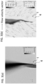
FIGs. 3(a) and (b) are schematic longitudinal sectional views showing the combustion state of coke oven emission gas that has undergone combustion using the combustion apparatus according to the above embodiment.FIG. 3(a) shows a flow velocity distribution.FIG. 3(b) shows a flow velocity vector and a temperature distribution. -
FIGs. 4(a) and 4(b) are schematic longitudinal sectional views showing the combustion state of coke oven emission gas that has undergone combustion using the combustion apparatus according to the above embodiment.FIG. 4(a) shows a pressure distribution when the ratio LID between the inner diameter D of a bleeder pipe and the distance L from the tip end of the bleeder pipe to the open end of the hood is 0.92, andFIG. 4(b) shows a pressure distribution when the ratio LID is 0.25. -
FIGs. 5(a) and 5(b) are schematic longitudinal sectional views showing the combustion state of coke oven emission gas that has been combusted using the combustion apparatus according to the above embodiment.FIG. 5(a) shows a gas flow when the ratio LID between the inner diameter D of the bleeder pipe and the distance L from the tip end of the bleeder pipe to the open end of the hood is 0.92, andFIG. 5(b) shows a gas flow when the ratio LID is 0.25. -
FIG. 6 is a graph showing the influence of the inner diameter d of the blow-in pipe on the relationship between the value of the left-hand side of Expression (1) and the ratio of the amount of soot generated in a combustion experiment for coke oven emission gas conducted using the combustion apparatus according to the above embodiment. -
FIG. 7 is a graph showing the relationship between the ratio LID of the distance L from the tip end of the bleeder pipe to the open end of the hood with respect to the inner diameter D of the bleeder pipe and the ratio of the amount of soot generated in a combustion experiment for coke oven emission gas conducted using the combustion apparatus according to the above embodiment. -
FIG. 8 is a schematic longitudinal sectional view showing the gap between the outer wall of the bleeder pipe and the inner wall of the hood, and the tilt angle of the blow-in pipe in the combustion apparatus according to the above embodiment. -
FIG. 9 is a graph showing the influence of the gap between the outer wall of the bleeder pipe and the inner wall of the hood and the tilt angle of the blow-in pipe on the ratio of the amount of soot generated in a combustion experiment for coke oven emission gas conducted using the combustion apparatus according to the above embodiment. -
FIG. 10 is a schematic view showing a conventional emission bleeder. -
FIGs. 11(a1) through (c2) are schematic views showing the relationship between the position of the blow-in pipe and a gas flow. Specifically,FIGS. 11(a1) and 11(a2) each show an example of the conventional emission bleeder,FIGS. 11(b1) and 11(b2) each show an example in which gas is blown into the gap between the outer wall of the bleeder pipe and the inner wall of the hood, andFIGS. 11(c1) and 11(c2) each show an example in which gas is blown from the center of the bleeder pipe. - Hereinafter, an embodiment of the present invention will be specifically described. Note that the drawings are only schematic and may differ from the actual ones. In addition, the following embodiment only describes examples of an apparatus and a method for embodying the technical idea of the present invention. Thus, the configuration of the present invention is not limited to the embodiments described below. That is, the technical idea of the present invention can be modified in various ways within the technical scope recited in the claims.
- An overview of a coke oven will be described with reference to
FIG. 2 . Acoke oven 11 includescarbonization chambers 12 andcombustion chambers 13 that are alternately arranged. In eachcombustion chamber 13, heat is generated by the combustion of combustion gas. In eachcarbonization chamber 12, coal is carbonized with the heat generated in theadjacent combustion chambers 13. During the carbonization process of coal, combustible gas called COG gas (hereinafter, C gas), which is a type of combustible gas, is generated. The C gas is composed mainly of H2, CO, and various other hydrocarbon gases, for example.FIG. 2 only shows twocarbonization chambers 12 and twocombustion chambers 13, but in practice, a large number of combinations ofcarbonization chambers 12 andcombustion chambers 13 are provided toward the depth side of the drawing. - Each of the
carbonization chambers 12 has ariser pipe 14 and a dry main 15 at its upper portion. Theriser pipe 14 collects C gas that has risen, and the dry main 15 aggregates the C gas sucked from the plurality ofcarbonization chambers 12 via theriser pipe 14. Anemission bleeder 1 is connected to the dry main 15. The C gas generated in the plurality ofcarbonization chambers 12 passes through theriser pipe 14 and the dry main 15, and is then discharged to the atmosphere through theemission bleeder 1. - During regular operation of a plant, C gas generated in each carbonization chamber is sucked and recovered by gas suction equipment (not shown) and then reused as an operation gas for various types of equipment. Meanwhile, in the event of trouble in a plant, such as a power failure, it would be impossible to sufficiently recover and reuse C gas generated in each carbonization chamber. As a result, it is necessary to discharge the C gas to the atmosphere as coke oven emission gas through the
emission bleeder 1. - As shown in
FIG. 1 , a combustion apparatus for coke oven gas according to the present embodiment includes theemission bleeder 1 and a control means 7 for controlling a combustion-promoting gas. Theemission bleeder 1 includes ahood 2, ableeder pipe 3, and blow-inpipes 4. AlthoughFIG. 1(a) shows an example in which thehood 2 is a single-wall cylindrical member and FIG. 2(b) shows an example in which the hood is a double-wall cylindrical member, the present invention is not limited thereto. Thebleeder pipe 3 communicates with the dry main 15 of thecoke oven 11, whereC gas 11G is generated, at one end (not shown), which is anend face 3B located in the lower portion of the drawing, allowing theC gas 11G to pass through toward thehood 2. InFIGS. 1(a) and 1(b) , theC gas 11G flows from the lower portion toward the upper portion. Thehood 2 discharges theC gas 11G, which has been fed from thebleeder pipe 3, to the atmosphere through oneend 2A (the upper end) open to the atmosphere. In addition, theother end 3A of thebleeder pipe 3 is enveloped within thehood 2. More specifically, theother end 2B (the lower end face) of thehood 2 is located at a position below theother end 3A (the upper end face) of thebleeder pipe 3 to thus form a region where thebleeder pipe 3 is enveloped within thehood 2. In the region where thebleeder pipe 3 is enveloped within thehood 2, agap 5 is formed between the inner wall of thehood 2 and the outer wall of thebleeder pipe 3. Note that the inner wall of thehood 2 is provided with anignition device 6 that first ignites theC gas 11G, which is the coke oven emission gas. - In the present embodiment, the blow-in
pipes 4 are provided, each of which can inject gas (hereinafter referred to as "combustion-promoting gas") in the inside of thehood 2 through thegap 5, which is formed between thebleeder pipe 3 and thehood 2. Each blow-inpipe 4 may be connected to a pump (not shown), for example, to feed a combustion-promoting gas by pressure. When the combustion-promoting gas is blown from the blow-inpipes 4, a flow of not only the combustion-promoting gas but also gas (hereinafter referred to as "associated gas"), such as air, which flows into thegap 5 by being entrained in a region around the combustion-promoting gas due to the effect of the gas viscosity, is generated. The combustion-promoting gas and the associated gas injected into thegap 5 rise along the outer wall of thebleeder pipe 3 and then are mixed with the coke oven emission gas (C gas 11G), which is fed from the inside of thebleeder pipe 3, inside of thehood 2, so that the gasses are stirred and mixed. After these gasses are stirred and mixed, they are ignited by theignition device 6. The resulting gas discharged from the upper end of thehood 2 is mixed with the outside air and thus combusted so that a flame (not shown) is formed in an upward direction from the upper end face of thebleeder pipe 3. In the present embodiment, the mixed gas of the combustion-promoting gas fed from the blow-inpipes 4, the C gas, and the combustion gas is discharged from the upper end of thehood 2 as a high-speed jet as indicated by a grayscale velocity distribution inFIG. 3(a) . InFIG. 3(a) , a darker portion indicates a higher velocity. As seen in a velocity vector indicated by the arrow and a temperature distribution indicated in grayscale inFIG. 3(b) , when the atmosphere is entrained in the high-speed jet, the coke oven emission gas (C gas), the combustion-promoting gas, and the associated gas are sufficiently stirred. Thus, the complete combustion of the C gas is promoted. In the present embodiment, the control means 7 is provided for adjusting the flow rate, flow velocity, or pressure of the combustion-promoting gas to be blown into the blow-inpipes 4. The control means 7 adjusts the blowing conditions for the combustion-promoting gas based on the information of the composition and flow rate of the C gas so as to promote the complete combustion of the coke oven emission gas. - The blow-in
pipes 4 may be provided at positions where they can inject the combustion-promoting gas into thegap 5, for example, may be provided such that the upper end face of the blow-inpipe 4 is located at a position below the upper end face of thebleeder pipe 3. One or more blow-inpipes 4 may be provided for a combination of thebleeder pipe 3 and thehood 2, and a plurality of blow-inpipes 4 may be provided in the circumferential direction of onebleeder pipe 3. In the present embodiment, it is possible to promote the complete combustion of the C gas, which is the coke oven emission gas, by entraining a sufficient amount of the atmosphere therein as long as the following Expression is satisfied:{MJ/(MG + MD)} × {0.5 × vJ 2 + γ/(γ - 1) × PJ/ρJ} ≥ 370000 × ln(d) + 2300000 FIG. 1(c) ). When a plurality of blow-in pipes are provided, the left-hand side of Expression (1) above may be set to Σ[MJ×{0.5×vJ 2+γ/ (γ-1)×PJ/ρJ}]/(MG+MD). Σ represents the sum of the blow-inpipes 4. This is based on the concept that, as long as, at a time when the combustion-promoting gas having the fluid energy defined as [MJ×{0.5×vJ 2+γ/ (γ-1)xPJ/ρJ] is entrained with the surrounding atmosphere to form a jet of a mixture gas (theoretical amount of air) with an emission gas and air necessary for the complete combustion of the amount of the emission gas, the mixture gas has energy {(MG+MD)×EML} [J] of a given level or higher, the complete combustion of the C gas is promoted and black smoke (the generation of soot) is thus reduced. EML represents the energy [J/kg] per unit mass. It is assumed that [MJ×{0.5×v J2+γ/(γ-1)×PJ/ρJ}]∝{(MG+MD)×EML} by assuming that the fluid energy of the combustion-promoting gas is proportional to the energy necessary for the complete combustion of the C gas. Since (MG+MD) can be calculated in advance, comparative evaluation was performed on a numerical value, which is obtained by dividing [MJ×{0.5×vJ 2+γ/(γ-1)×PJ/ρJ}] by (MG+MD), and the amount of soot generated. Then, it was found that the expression can be arranged with the above indices. Since there are a pressure loss due to viscosity and a flow velocity distribution within the jet, EML cannot be determined theoretically, but the inventors have found that EML based on the above concept can be expressed as 370000×ln(d)+2300000 as described in examples below. - The combustion-promoting gas is not limited to any particular gas as long as it is gas, but it is preferably incombustible gas to prevent explosion in the
hood 2 and incomplete combustion. In particular, among incombustible gases, a mixed gas of one or more selected from air, nitrogen gas, and water vapor is preferably used. Even when nitrogen gas containing no oxygen is adopted as the combustion-promoting gas, it is possible to promote the complete combustion of the C gas because the high-speed jet entrains a sufficient amount of atmosphere (i.e., associated gas), and oxygen contained in the entrained atmosphere thus reacts with the C gas as described above. - Applying the combustion apparatus for coke oven emission gas of the present embodiment to the
coke oven 11 can, even in the event of trouble such as a power outage, promote the complete combustion of C gas generated in and emitted from thecarbonization chambers 12, and thus allow the C gas to be discharged into the atmosphere as a less harmful substance, like CO2 and H2O. In addition, when the combustion apparatus is applied to thecoke oven 11, air is preferably used as gas to be injected through the blow-inpipes 4. When air is used as a combustion-promoting gas in a plant, the combustion-promoting gas can be supplied to theemission bleeder 1 more easily and promptly than when other gases are used, even in an emergency. - Further, provided that the inner diameter of the
bleeder pipe 3 is represented by D [m], and the distance from the tip end (theupper end face 3A) of the bleeder pipe to the tip end (theupper end face 2A) of the hood is represented by L [m], the ratio LID [-] is preferably set to the range of 0.5 to 2.5, inclusive. As shown by a pressure distribution inFIG. 4(a) , when L/D=0.92, which falls within the above range, and a high-speed jet of combustion-promoting gas is blown into thehood 2 from the blow-inpipes 4, the high-speed jet generates a sufficient negative-pressure region in thehood 2 at a position above theupper end face 3A of thebleeder pipe 3. The negative pressure causes the atmosphere (air) to be suddenly sucked on the atmosphere side of theupper end face 2A of thehood 2, so that the atmosphere and the coke oven emission gas are stirred and mixed, and thus, oxygen is supplied to the inside of a flame. This can promote the combustion of the C gas, which is the coke oven emission gas. - Meanwhile, as shown by a pressure distribution in
FIG. 4(b) , when the ratio L/D=0.25<0.5 is satisfied, a sufficient negative-pressure region is not formed in thehood 2, reducing the effect of blowing in the combustion-promoting gas. That is, the ratio LID is preferably 0.5 or more. Meanwhile, if the ratio LID is too high, an energy loss occurs due to friction between the fluids and due to friction between the fluid and the wall surface resulting from viscosity. Thus, the ratio LID is preferably set to 2.5 or less. - The mechanism in which the amount of soot generated in the combustion apparatus according to the present embodiment is reduced will be described with reference to
FIG. 5 as an example. The flow velocity of a jet FJ blown in from the blow-inpipe 4 is higher than the flow velocity of the C gas FU. Therefore, the C gas FU is first entrained in the jet FJ within thehood 2. When the jet FJ with the C gas FU sufficiently entrained therein comes out of thehood 2, the jet FJ entrains a large amount of the atmosphere FA. This promotes the mixing of the C gas and air, and the C gas is thus expected to be completely combusted. Moreover, the large amount of air causes the combustion temperature to be lowered, thus reducing the generation of soot. In this case, as shown inFIG. 5(a) , thehood 2 needs to be kept sufficiently high. When thehood 2 is not sufficiently high as shown inFIG. 5(b) , the atmosphere outside the hood will be entrained in the jet FJ before the C gas is sufficiently entrained in the jet FJ, which in turn makes it difficult to sufficiently mix the C gas and air. - The combustion apparatus for coke oven emission gas according to the present embodiment includes a control means for adjusting one or more selected from the gas flow rate MJ, the gas flow velocity vJ, and the gas pressure PJ of the combustion-promoting gas to be blown in through the blow-in pipe(s) 4 so as to satisfy Expression (1) above based on information on the composition and the amount of the C gas generated grasped in advance, information on a flowmeter provided in the
bleeder pipe 3, or information obtained by analyzing the C gas in thebleeder pipe 3. The control means may be configured from a computer, for example. - The combustion method for coke oven emission gas that uses the combustion apparatus for coke oven emission gas according to the present embodiment includes adjusting one or more in combination selected from the gas flow rate MJ, the gas flow velocity vJ, and the gas pressure PJ of the combustion-promoting gas based on the composition and the amount of the C gas generated.
- The method of designing a combustion apparatus for coke oven emission gas according to the present embodiment includes designing the inner diameter d [m] of the blow-in pipe so as to satisfy Expression (1) above based on the range of the composition of the coke oven emission gas and the transition of the amount of the gas generated, which have been grasped in advance, and on the controllable values of the combustion-promoting gas, such as the gas flow rate range, pressure range, and physical properties. Note that when a plurality of blow-in
pipes 4 are used, it is preferable to design the inner diameter d [m] of each blow-in pipe by correcting Expression (1) using the sum of the fluid energy of the combustion-promoting gas. Note that thegap 5 between the inner wall of thehood 2 and the outer wall of the bleeder pipe is designed such that at least the blow-in pipe(s) 4 can be inserted into thegap 5. - In the present example, the amount of soot generated, which is the main component of black smoke, was attempted to be quantitatively evaluated through simulation. Specifically, NuFD/FrontFlowRed was used as the simulation software to reproduce the combustion of a coke oven gas with each emission bleeder. Then, the condition of a flame (i.e., the flame temperature) was examined, and the amount of soot generated in each of a case where no blow-in pipe is provided (conventional example) and a case where a blow-in pipe is provided (invention example) was examined as the ratio of the amount of soot generated, provided that the amount of soot generated in the conventional example is 1.0. The amount of soot generated is defined as the maximum value of the total amount of soot across horizontal cross-sections in the simulation. The ordinate axis of
FIG. 6 represents the ratio φ of the maximum value of the maximum amount of soot generated under each blowing condition with respect to the maximum amount of soot generated in the conventional example. The abscissa axis ofFIG. 6 represents the left-hand side of Expression (1). This corresponds to a value obtained by dividing the energy of the combustion-promoting gas by the sum of the mass flow rate of the coke oven gas and the mass flow rate of air necessary for the complete combustion of the coke oven gas.FIG. 6 shows that the ratio φ of the amount of soot generated decreases after the left-hand side of Expression (1) attains a given value or more for each of the different inner diameters d of the blow-inpipe 4. The ratio φ of the amount of soot generated is also approximated to a curve using a sigmoid function. Provided that φ=1-{1/ (1+e-α(x-β))}, where α=5.00005 and β=370000×ln (d) +2300000, it is found that each plot can be roughly approximated to a curve. Here, β is the inflection point of the function, and is also a point at which φ is 0.5, that is, the amount of soot generated is 0.5 with respect to that of the conventional example. This indicates that when Expression (1) above is satisfied, the complete combustion of a C gas is promoted, reducing black smoke (i.e., the generation of soot). - Next,
FIG. 7 shows the simulation results of examining the amount of soot generated by changing the ratio LID variously while fixing the other conditions to d=0.01[m] and {MJ/(MG+MD)}×{0.5×vJ 2+γ/(γ-1)×PJ/ρJ}=7.75×105 [J/kg]. FromFIG. 7 , it is found that the ratio φ of the amount of soot generated is minimum when the ratio LID is close to 1. When the ratio LID is less than 1, the amount of soot generated suddenly increases. Meanwhile, when the ratio LID is more than 1, the amount of soot generated moderately increases. When a high-speed jet of a combustion-promoting gas is blown into thehood 2 from the blow-inpipe 4, negative pressure is generated in thehood 2 at a position above thetip end 3A of the bleeder pipe due to the entrainment of the high-speed jet. The negative pressure causes the atmosphere (air) to be suddenly sucked on the atmosphere side of theupper end 2A of thehood 2, so that the atmosphere and the coke oven emission gas are stirred and mixed. This allows oxygen to be supplied to the inside of a flame, and thus can promote the combustion of the C gas that is the coke oven emission gas. As shown inFIG. 4(b) , under the condition of 0.5>L/D, negative pressure is not sufficiently formed in thehood 2, thus reducing the effect of blowing in the combustion-promoting gas. Meanwhile, when LID is too high, the fluid energy is gradually reduced due to the viscosity between the fluids and the viscosity between the fluid and the wall inside thehood 2. As a result, the effect of entraining the atmosphere at the upper end of the hood is reduced. Therefore,FIG. 7 shows that the ratio LID is preferably in the range of 0.5 to 2.5, inclusive. - The influence of the gap W [m] between the outer wall of the
bleeder pipe 3 and the inner wall of thehood 2, and the angle θ [°] of the blow-in pipe in the axial direction on the amount of soot generated was examined using simulation software as in Example 1.FIG. 9 shows the results of the amount of soot generated with the inner diameter of the blow-in pipe represented by d [m]. The abscissa axis ofFIG. 9 represents W/ (d·cosθ). The ordinate axis ofFIG. 9 represents the ratio of the amount of soot generated as in Example 1. Besides, when the angle θ is too large, the upward motion component decreases while the lateral motion component increases. In such a case, when a jet collides with the bleeder pipe, the jet spreads over a wide range, with the result that the effect of reducing soot through the entrainment of the jet cannot be sufficiently achieved. Thus, the angle θ is preferably in the range of 0° to 30°, inclusive. - The result shows that a jet can sufficiently entrain the atmosphere and thus promote the complete combustion of a C gas, which is coke oven emission gas, provided that the following two conditions are met: the angle θ is between 0° and 30°, inclusive, and the value of W/(d·cosθ) is in the range of 0.85 to 1.6, inclusive.
- When the gap W is too small, a jet from the blow-in
pipe 4 cannot sufficiently enter the inside of the hood, causing it to flow out to the atmosphere side. Consequently, the effect of blowing in the jet is reduced. With respect to the gap W, d·cosθ is an area obtained by projecting a cross-section of the blow-in pipe onto the gap between the hood and the bleeder pipe. Even W/ (d·cosθ) of less than 1 is considered to be in the preferable range. This is because the jet flows along the wall surface while being attracted by the Coanda effect of the jet and the wall surface.FIG. 9 shows that W/ (d·cosθ) of 0.85 or more allows the entire jet to flow inside the hood, which effectively achieves the effect of reducing the amount of soot generated. Meanwhile, if the gap W is too large, the atmosphere is likely to be sucked in through the gap, reducing the negative-pressure region in the upper portion of the hood and the pressure difference with the surrounding. According toFIG. 9 , it can be observed that when W/ (d·cosθ) is 1.6 or less, the effect of suppressing soot generation can be efficiently achieved. -
FIG. 11(a1) shows, as a conventional example, a longitudinal section of an emission bleeder that operates without blowing in gas.FIG. 11(b1) shows the arrangement of a blow-inpipe 4 according to the above embodiment as an invention example.FIG. 11(c1) , as a comparative example, shows thebleeder pipe 3 with a blow-inpipe 4A arranged in the center.FIGS. 11(a2), 11(b2), and 11(c2) show the results of fluid simulation of the conventional example, the invention example, and the comparative example, respectively. The invention example shows the state where the surrounding atmosphere and the jet are mixed above the hood. Meanwhile, the conventional example and the comparative example have a lower force of drawing in the surrounding atmosphere, compared to the invention example. - Accordingly, it has been verified through simulation that combustion efficiency for coke oven emission gas can be improved according to the example of the invention.
- The combustion apparatus for coke oven emission gas, the combustion method for coke oven emission gas, and the method of designing the combustion apparatus for coke oven emission gas according to the present invention are each applicable to a case where combustible gas requires complete combustion before being discharged to the atmosphere.
-
- 1
- emission bleeder
- 2
- hood
- 2A
- upper end face of hood
- 2B
- lower end face of hood
- 3
- bleeder pipe
- 3A
- upper end face of bleeder pipe
- 3B
- end of bleeder pipe on side of coke oven
- 4
- blow-in pipe
- 4A
- blow-in pipe (located in center of bleeder pipe)
- 5
- gap (gap between outer wall of bleeder pipe and inner wall of hood)
- 6
- ignition device
- 7
- control means
- 11
- coke oven
- 11G
- coke oven gas (C gas or combustible gas)
- 12
- carbonization chamber
- 13
- combustion chamber
- 14
- riser pipe
- 15
- dry main
- d
- inner diameter of blow-in pipe
- D
- diameter of upper end of bleeder pipe
- L
- distance from upper end of bleeder pipe to open end of hood
- W
- length of gap between outer wall of bleeder pipe and inner wall of hood
- FJ
- jet
- FA
- atmosphere (air)
- FU
- combustible gas (C gas)
Claims (7)
- A combustion apparatus for coke oven emission gas comprisinga bleeder pipe having one end that communicates with a portion where the coke oven emission gas is generated and allowing the coke oven emission gas to pass through its insidea hood having one end open to an atmosphere side and the other end enveloping the other end of the bleeder pipe, arranged so as to be coaxial with an axis of the other end of the bleeder pipe, and formed of at least one cylinder,a gas blow-in pipe inserted from below into a gap between an outer wall of the bleeder pipe and an inner wall of the hood, anda control means for adjusting a blowing condition for combustion-promoting gas to be blown from the gas blow-in pipe,characterized in thatthe control means is configured to adjust one or more in combination selected from a gas flow rate MJ [kg/s], a gas flow velocity vJ [m/s], and gas pressure PJ [Pa] of the combustion-promoting gas to be blown through the blow-in pipe so as to satisfy Expression (1) below:
{MJ/(MG + MD)} × {0.5 × vJ 2 + γ/(γ - 1) × PJ/ρJ} ≥ 370000 × ln(d) + 2300000 MG represents a flow rate [kg/s] of the emission gas in the bleeder pipe,MD represents a theoretical flow rate [kg/s] of air necessary for combustion of the emission gas,γ represents a specific heat ratio,ρJ represents a density [kg/m3] of the combustion-promoting gas, andd represents an inner diameter [m] of the blow-in pipe. - The combustion apparatus for coke oven emission gas according to claim 1, wherein
a ratio LID is between 0.5 and 2.5, inclusive, provided that an inner diameter of the bleeder pipe is D [m] and a distance from a tip of the other end of the bleeder pipe to a tip of the one end of the hood is L [m]. - The combustion apparatus for coke oven emission gas according to claim 1 or 2, wherein
an angle θ is between 0° and 30°, inclusive, and a value of W/ (d·cosθ) is in a range of 0.85 to 1.6, inclusive, provided that the gap between the outer wall of the bleeder pipe and the inner wall of the hood is W [m], the inner diameter of the blow-in pipe is d [m], and an angle formed between the bleeder pipe in an axial direction and the blow-in pipe in the axial direction is θ [°]. - A combustion method for coke oven emission gas comprisingallowing coke oven emission gas to pass through the inside of a bleeder pipe having one end that communicates with a portion where the coke oven emission gas is generated,providing a hood having one end open to an atmosphere side and the other end enveloping the other end of the bleeder pipe, arranged so as to be coaxial with an axis of the other end of the bleeder pipe, and formed of at least one cylinder, andblowing combustion-promoting gas through a blow-in pipe inserted into a gap between an inner wall of the hood and an outer wall of the bleeder pipe,characterized in thatthe method further comprises adjusting one or more in combination selected from a gas flow rate MJ [kg/s], a gas flow velocity vJ [m/s], and gas pressure PJ [Pa] of the combustion-promoting gas to be blown through the blow-in pipe so as to satisfy Expression (1):
{MJ/(MG + MD)} × {0.5 × vJ 2 + γ/(γ - 1) × PJ/ρJ} ≥ 370000 × ln(d) + 2300000 MG represents a flow rate [kg/s] of the emission gas in the bleeder pipe,MD represents a theoretical flow rate [kg/s] of air necessary for combustion of the emission gas,γ represents a specific heat ratio,ρJ represents a density [kg/m3] of the combustion-promoting gas, andd represents an inner diameter [m] of the blow-in pipe. - A method of designing a combustion apparatus for coke oven emission gas comprisinga bleeder pipe having one end that communicates with a portion where the coke oven emission gas is generated and allowing the coke oven emission gas to pass through an inside of the bleeder pipe,a hood having one end open to an atmosphere side and the other end enveloping the other end of the bleeder pipe, arranged so as to be coaxial with an axis of the other end of the bleeder pipe, and formed of at least one cylinder,a gas blow-in pipe inserted from below into a gap between an outer wall of the bleeder pipe and an inner wall of the hood, anda control means for adjusting a blowing condition for combustion-promoting gas to be blown through the gas blow-in pipe,characterized in thatthe method further comprises designing an inner diameter d [m] of the blow-in pipe so as to satisfy Expression (1):
{MJ/(MG + MD)} × {0.5 × vJ 2 + γ/(γ - 1) × PJ/ρJ} ≥ 370000 × ln(d) + 2300000 MG represents a flow rate [kg/s] of the emission gas in the bleeder pipe,MD represents a theoretical flow rate [kg/s] of air necessary for combustion of the emission gas,γ represents a specific heat ratio,ρJ represents a density [kg/m3] of the combustion-promoting gas, andd represents an inner diameter [m] of the blow-in pipe. - The method of designing a combustion apparatus for coke oven emission gas according to claim 5, wherein
a ratio LID is set in a range of 0.5 to 2.5, inclusive, provided that an inner diameter of the bleeder pipe is D [m], and a distance from a tip of the other end of the bleeder pipe to a tip of the one end of the hood is L [m]. - The method of designing a combustion apparatus for coke oven emission gas according to claim 5 or 6, wherein
an angle θ is set in a range of 0° to 30°, inclusive, and a value of W/(d·cosθ) is set in a range of 0.85 to 1.6, inclusive, provided that the gap between the outer wall of the bleeder pipe and the inner wall of the hood is W [m], the inner diameter of the blow-in pipe is d [m], and an angle formed between the bleeder pipe in an axial direction and the blow-in pipe in the axial direction is θ [°].
Applications Claiming Priority (2)
| Application Number | Priority Date | Filing Date | Title |
|---|---|---|---|
| JP2022011501 | 2022-01-28 | ||
| PCT/JP2022/043090 WO2023145219A1 (en) | 2022-01-28 | 2022-11-22 | Device for combusting coke oven emission gases, method of combusting coke oven emission gases, and method of designing device for combusting coke oven emission gases |
Publications (2)
| Publication Number | Publication Date |
|---|---|
| EP4467875A1 true EP4467875A1 (en) | 2024-11-27 |
| EP4467875A4 EP4467875A4 (en) | 2025-04-23 |
Family
ID=87471412
Family Applications (1)
| Application Number | Title | Priority Date | Filing Date |
|---|---|---|---|
| EP22924071.8A Pending EP4467875A4 (en) | 2022-01-28 | 2022-11-22 | Apparatus for combusting coke oven off-gases, method for combusting coke oven off-gases, and method for designing an apparatus for combusting coke oven off-gases |
Country Status (4)
| Country | Link |
|---|---|
| EP (1) | EP4467875A4 (en) |
| JP (1) | JPWO2023145219A1 (en) |
| TW (1) | TWI852282B (en) |
| WO (1) | WO2023145219A1 (en) |
Family Cites Families (8)
| Publication number | Priority date | Publication date | Assignee | Title |
|---|---|---|---|---|
| US4643669A (en) | 1985-08-26 | 1987-02-17 | Peabody Engineering Corporation | Smokeless flare gas burner |
| FR2788112B1 (en) | 1998-12-30 | 2001-06-08 | Total Raffinage Distribution | TORCHERE-TYPE APPARATUS AND METHOD FOR THE COMBUSTION OF GAS |
| DK1397614T3 (en) | 2001-04-18 | 2012-07-09 | Saudi Arabian Oil Co | Burning tower combustion apparatus and method |
| US7354265B2 (en) * | 2004-12-02 | 2008-04-08 | Saudi Arabian Oil Company | Flare stack combustion method and apparatus |
| US20100291492A1 (en) | 2009-05-12 | 2010-11-18 | John Zink Company, Llc | Air flare apparatus and method |
| CN103499097B (en) * | 2013-09-29 | 2016-05-11 | 北京华清燃气轮机与煤气化联合循环工程技术有限公司 | A kind of combustion chambers burn method for organizing and nozzle that uses medium and low heat value fuel gas |
| JP2017096615A (en) * | 2015-11-18 | 2017-06-01 | Jfeスチール株式会社 | Diffusion breeder |
| JP7143774B2 (en) * | 2019-01-23 | 2022-09-29 | 日本製鉄株式会社 | Combustion pipe for coke oven gas |
-
2022
- 2022-11-22 EP EP22924071.8A patent/EP4467875A4/en active Pending
- 2022-11-22 JP JP2023514457A patent/JPWO2023145219A1/ja active Pending
- 2022-11-22 WO PCT/JP2022/043090 patent/WO2023145219A1/en not_active Ceased
-
2023
- 2023-01-12 TW TW112101377A patent/TWI852282B/en active
Also Published As
| Publication number | Publication date |
|---|---|
| WO2023145219A1 (en) | 2023-08-03 |
| TWI852282B (en) | 2024-08-11 |
| JPWO2023145219A1 (en) | 2023-08-03 |
| TW202344777A (en) | 2023-11-16 |
| EP4467875A4 (en) | 2025-04-23 |
Similar Documents
| Publication | Publication Date | Title |
|---|---|---|
| EP0160146B1 (en) | Apparatus for coal combustion | |
| JPH0611120A (en) | Low NOx generating gas burner apparatus and method | |
| CN88100956A (en) | Low concentration nitrogen oxide (NOx) combustion device | |
| US8118588B2 (en) | Energy efficient low NOx burner and method of operating same | |
| RU2670506C2 (en) | Start-up torch | |
| KR20080069970A (en) | Process and apparatus for low-nitrogen combustion | |
| JP3938358B2 (en) | Flare stack combustion apparatus and method | |
| JP2002115809A (en) | DILUTION METHOD AND APPARATUS FOR FUEL FOR REDUCING NOx | |
| PL212230B1 (en) | Low nox combustion | |
| CN1139743C (en) | Improvement of Flat Flame Burner | |
| JPH09188985A (en) | Combustion system for black liquor recovering boiler | |
| SE439363B (en) | NITROGEN FUEL BURNER | |
| EP0688414B1 (en) | Apparatus and method for burning combustible gases | |
| CN109073218B (en) | Incineration system | |
| TWI852282B (en) | Combustion device for coke furnace gas, combustion method for coke furnace gas, and design method for combustion device for coke furnace gas | |
| RU2745312C1 (en) | Exhaust gas torch with low steam consumption and high smoke capabilities | |
| RU2446195C1 (en) | Method of producing low-dispersed technical carbon and reactor for realising said method | |
| EP4150253B1 (en) | Burner and method for the firing of ceramic articles | |
| CN117739350A (en) | Sulfur recovery tail gas incineration equipment and tail gas treatment method | |
| JPH0571706A (en) | Combustion method for simultaneously inhibiting nitrogen oxide and incomplete combustion product | |
| CN219756388U (en) | Cyanide-containing waste gas treatment device | |
| US10429072B2 (en) | Regenerative burner for non-symmetrical combustion | |
| US12590412B2 (en) | Recovery boiler startup burner assembly | |
| TW202609065A (en) | Injection lance, use thereof, blast furnace comprising the same and tuyere assembly for a blast furnace | |
| JP3347696B2 (en) | Incinerator |
Legal Events
| Date | Code | Title | Description |
|---|---|---|---|
| STAA | Information on the status of an ep patent application or granted ep patent |
Free format text: STATUS: THE INTERNATIONAL PUBLICATION HAS BEEN MADE |
|
| PUAI | Public reference made under article 153(3) epc to a published international application that has entered the european phase |
Free format text: ORIGINAL CODE: 0009012 |
|
| STAA | Information on the status of an ep patent application or granted ep patent |
Free format text: STATUS: REQUEST FOR EXAMINATION WAS MADE |
|
| 17P | Request for examination filed |
Effective date: 20240822 |
|
| AK | Designated contracting states |
Kind code of ref document: A1 Designated state(s): AL AT BE BG CH CY CZ DE DK EE ES FI FR GB GR HR HU IE IS IT LI LT LU LV MC ME MK MT NL NO PL PT RO RS SE SI SK SM TR |
|
| A4 | Supplementary search report drawn up and despatched |
Effective date: 20250324 |
|
| RIC1 | Information provided on ipc code assigned before grant |
Ipc: F23G 7/06 20060101ALI20250318BHEP Ipc: F23G 7/08 20060101AFI20250318BHEP |
|
| DAV | Request for validation of the european patent (deleted) | ||
| DAX | Request for extension of the european patent (deleted) | ||
| GRAP | Despatch of communication of intention to grant a patent |
Free format text: ORIGINAL CODE: EPIDOSNIGR1 |
|
| STAA | Information on the status of an ep patent application or granted ep patent |
Free format text: STATUS: GRANT OF PATENT IS INTENDED |
|
| INTG | Intention to grant announced |
Effective date: 20260331 |