EP4467859A1 - Double seal arrangement - Google Patents
Double seal arrangement Download PDFInfo
- Publication number
- EP4467859A1 EP4467859A1 EP24177264.9A EP24177264A EP4467859A1 EP 4467859 A1 EP4467859 A1 EP 4467859A1 EP 24177264 A EP24177264 A EP 24177264A EP 4467859 A1 EP4467859 A1 EP 4467859A1
- Authority
- EP
- European Patent Office
- Prior art keywords
- tube
- flange
- gasket
- tabs
- sheet metal
- Prior art date
- Legal status (The legal status is an assumption and is not a legal conclusion. Google has not performed a legal analysis and makes no representation as to the accuracy of the status listed.)
- Granted
Links
Images



Classifications
-
- F—MECHANICAL ENGINEERING; LIGHTING; HEATING; WEAPONS; BLASTING
- F16—ENGINEERING ELEMENTS AND UNITS; GENERAL MEASURES FOR PRODUCING AND MAINTAINING EFFECTIVE FUNCTIONING OF MACHINES OR INSTALLATIONS; THERMAL INSULATION IN GENERAL
- F16L—PIPES; JOINTS OR FITTINGS FOR PIPES; SUPPORTS FOR PIPES, CABLES OR PROTECTIVE TUBING; MEANS FOR THERMAL INSULATION IN GENERAL
- F16L19/00—Joints in which sealing surfaces are pressed together by means of a member, e.g. a swivel nut, screwed on, or into, one of the joint parts
- F16L19/02—Pipe ends provided with collars or flanges, integral with the pipe or not, pressed together by a screwed member
- F16L19/025—Pipe ends provided with collars or flanges, integral with the pipe or not, pressed together by a screwed member the pipe ends having integral collars or flanges
-
- F—MECHANICAL ENGINEERING; LIGHTING; HEATING; WEAPONS; BLASTING
- F02—COMBUSTION ENGINES; HOT-GAS OR COMBUSTION-PRODUCT ENGINE PLANTS
- F02C—GAS-TURBINE PLANTS; AIR INTAKES FOR JET-PROPULSION PLANTS; CONTROLLING FUEL SUPPLY IN AIR-BREATHING JET-PROPULSION PLANTS
- F02C7/00—Features, components parts, details or accessories, not provided for in, or of interest apart form groups F02C1/00 - F02C6/00; Air intakes for jet-propulsion plants
- F02C7/28—Arrangement of seals
-
- F—MECHANICAL ENGINEERING; LIGHTING; HEATING; WEAPONS; BLASTING
- F16—ENGINEERING ELEMENTS AND UNITS; GENERAL MEASURES FOR PRODUCING AND MAINTAINING EFFECTIVE FUNCTIONING OF MACHINES OR INSTALLATIONS; THERMAL INSULATION IN GENERAL
- F16L—PIPES; JOINTS OR FITTINGS FOR PIPES; SUPPORTS FOR PIPES, CABLES OR PROTECTIVE TUBING; MEANS FOR THERMAL INSULATION IN GENERAL
- F16L23/00—Flanged joints
- F16L23/16—Flanged joints characterised by the sealing means
-
- F—MECHANICAL ENGINEERING; LIGHTING; HEATING; WEAPONS; BLASTING
- F16—ENGINEERING ELEMENTS AND UNITS; GENERAL MEASURES FOR PRODUCING AND MAINTAINING EFFECTIVE FUNCTIONING OF MACHINES OR INSTALLATIONS; THERMAL INSULATION IN GENERAL
- F16L—PIPES; JOINTS OR FITTINGS FOR PIPES; SUPPORTS FOR PIPES, CABLES OR PROTECTIVE TUBING; MEANS FOR THERMAL INSULATION IN GENERAL
- F16L41/00—Branching pipes; Joining pipes to walls
- F16L41/08—Joining pipes to walls or pipes, the joined pipe axis being perpendicular to the plane of a wall or to the axis of another pipe
- F16L41/086—Joining pipes to walls or pipes, the joined pipe axis being perpendicular to the plane of a wall or to the axis of another pipe fixed with screws
-
- F—MECHANICAL ENGINEERING; LIGHTING; HEATING; WEAPONS; BLASTING
- F16—ENGINEERING ELEMENTS AND UNITS; GENERAL MEASURES FOR PRODUCING AND MAINTAINING EFFECTIVE FUNCTIONING OF MACHINES OR INSTALLATIONS; THERMAL INSULATION IN GENERAL
- F16J—PISTONS; CYLINDERS; SEALINGS
- F16J15/00—Sealings
- F16J15/02—Sealings between relatively-stationary surfaces
- F16J15/06—Sealings between relatively-stationary surfaces with solid packing compressed between sealing surfaces
- F16J15/061—Sealings between relatively-stationary surfaces with solid packing compressed between sealing surfaces with positioning means
-
- F—MECHANICAL ENGINEERING; LIGHTING; HEATING; WEAPONS; BLASTING
- F16—ENGINEERING ELEMENTS AND UNITS; GENERAL MEASURES FOR PRODUCING AND MAINTAINING EFFECTIVE FUNCTIONING OF MACHINES OR INSTALLATIONS; THERMAL INSULATION IN GENERAL
- F16J—PISTONS; CYLINDERS; SEALINGS
- F16J15/00—Sealings
- F16J15/02—Sealings between relatively-stationary surfaces
- F16J15/06—Sealings between relatively-stationary surfaces with solid packing compressed between sealing surfaces
- F16J15/08—Sealings between relatively-stationary surfaces with solid packing compressed between sealing surfaces with exclusively metal packing
- F16J15/0818—Flat gaskets
- F16J15/0825—Flat gaskets laminated
- F16J15/0831—Flat gaskets laminated with mounting aids
-
- F—MECHANICAL ENGINEERING; LIGHTING; HEATING; WEAPONS; BLASTING
- F16—ENGINEERING ELEMENTS AND UNITS; GENERAL MEASURES FOR PRODUCING AND MAINTAINING EFFECTIVE FUNCTIONING OF MACHINES OR INSTALLATIONS; THERMAL INSULATION IN GENERAL
- F16L—PIPES; JOINTS OR FITTINGS FOR PIPES; SUPPORTS FOR PIPES, CABLES OR PROTECTIVE TUBING; MEANS FOR THERMAL INSULATION IN GENERAL
- F16L23/00—Flanged joints
- F16L23/02—Flanged joints the flanges being connected by members tensioned axially
-
- F—MECHANICAL ENGINEERING; LIGHTING; HEATING; WEAPONS; BLASTING
- F16—ENGINEERING ELEMENTS AND UNITS; GENERAL MEASURES FOR PRODUCING AND MAINTAINING EFFECTIVE FUNCTIONING OF MACHINES OR INSTALLATIONS; THERMAL INSULATION IN GENERAL
- F16L—PIPES; JOINTS OR FITTINGS FOR PIPES; SUPPORTS FOR PIPES, CABLES OR PROTECTIVE TUBING; MEANS FOR THERMAL INSULATION IN GENERAL
- F16L23/00—Flanged joints
- F16L23/16—Flanged joints characterised by the sealing means
- F16L23/18—Flanged joints characterised by the sealing means the sealing means being rings
- F16L23/20—Flanged joints characterised by the sealing means the sealing means being rings made exclusively of metal
Definitions
- the application relates generally to a double seal arrangement and, more particularly, to a double seal arrangement including a self-attaching gasket at a flange interface between a tube fitting and an engine component of a gas turbine engine.
- Fluid lines are used to route various fluids (e.g., air, oil or fuel) throughout a gas turbine engine.
- Certain portions of fluid lines, such as tubes may be detachably coupled to other portions of fluid lines and/or to engine structures, such as engine accessories and engine casings.
- engine structures such as engine accessories and engine casings.
- access and visibility to the tube coupling interface during the time of assembly may be restricted. Such situations impose challenges for the proper positioning of a seal at the coupling interface prior to torquing the tube to the adjoining engine component.
- a tube assembly for a gas turbine engine comprising: a tube having a tube end and a tube flange projecting from the tube end to a peripheral wall circumscribing the tube flange; an engine component having a tube mounting surface surrounding a fluid port fluidly connected to the tube, the tube end engaged in the fluid port and defining a bore interface therebetween, a flange interface defined between the tube mounting surface and the tube flange; a first seal at the bore interface between the tube and the fluid port of the engine component; a second seal at the flange interface between the tube flange and the tube mounting surface of the engine component, the second seal including a gasket, the gasket having: a sheet metal body having a tube facing side and an engine component facing side opposite to the tube facing side; corrugations projecting from the tube facing side; and tabs distributed along a periphery of the sheet metal body, the tabs spring loaded against the peripheral wall of the tube flange, the tabs resiliently holding the gasket on the
- the tabs and the corrugations project outwardly from the tube facing side of the sheet metal body, and wherein the tabs have a height greater than that of the corrugations.
- the tube flange and the tube mounting surface are respectively made of a first and a second material, the second material of the tube mounting surface being softer that the first material of the tube flange, the corrugations of the gasket elastically and/or plastically deformed against the tube flange.
- the gasket is self-centered on the tube flange by a snap on engagement of the tabs with the peripheral wall of the tube flange.
- the sheet metal body has a diamond shape including four straight side edges, and wherein the tabs include one or more tabs on each of the straight side edges.
- the corrugations include a central annular corrugation concentric with a central hole defined in the sheet metal body of the gasket, and a first pair and a second pair of linear corrugations disposed outside of the central annular corrugation, the sheet metal body having a first bolt hole and a second bolt hole defined therethrough on diametrically opposed sides of the central hole, the first bolt hole disposed between the linear corrugations of the first pair of linear corrugations, the second bolt hole disposed between the linear corrugations of the second pair of linear corrugations.
- the sheet metal body is made out of stainless steel, and wherein the sheet metal body has a thickness comprised between 5 thou and 20 thou.
- the sheet metal body has an anti-friction coating applied over one or more of the tube facing side and the engine component facing side.
- the tube flange has a first side facing the engine component and a second opposed side, and wherein the tabs are disposed to fit tightly against the peripheral wall of the tube flange and to project beyond the peripheral wall on the second opposed side of the tube flange after the gasket has been snapped into position on the tube flange.
- each of the tabs has a rounded lip formed at a free distal end thereof, the rounded lip accessible from the second opposed side of the tube flange.
- the first material of the tube flange is stainless steel and the second material of the tube mounting surface is aluminium, and wherein the sheet metal body of the gasket is made of stainless steel, the corrugations deformed against the tube flange by a torque applied to the fasteners.
- the sheet metal body has a thickness of about 7 thou.
- a dual seal arrangement between a tube fitting and an accessory of a gas turbine engine comprising: an O-ring at a bore interface between the tube fitting and a fluid port of the accessory; and a metal gasket at a flange interface between a flange of the tube fitting and the accessory, the metal gasket having: a tube fitting side and an accessory facing side; deformable corrugations projecting from the tube fitting side; spring-loaded tabs distributed about a perimeter of the metal gasket, the spring-loaded tabs projecting outwardly from the tube fitting side and disposed for firmly resiliently grasping a peripheral wall of the flange of the tube fitting; and a first and a second bolt hole disposed on opposed sides of a central hole, the central hole concentric with the O-ring at the bore interface, the spring-loaded tabs disposed around the central hole in diametrically opposed pairs, the first and second bolt holes disposed between adjacent ones of the spring-loaded tabs.
- the metal gasket has a diamond-shape sheet metal body including four straight sides joined by rounded corners, the spring-loaded tabs disposed centrally along the straight sides.
- the metal gasket is made of a material having a surface hardness similar to that of the flange of the tube fitting.
- the surface hardness of the metal gasket is greater than that of a mating surface of the accessory.
- a surface area of the metal gasket generally corresponds to that of the flange of the tube fitting, and wherein the metal gasket has a thickness ranging from 5 thou to 20 thou.
- an anti-friction coating is applied on the metal gasket.
- each of the spring-loaded tabs has a rounded lip formed at a free distal end thereof, the rounded lip forming an inwardly facing bump for engagement with the flange of the tube fitting.
- the spring-loaded tabs extend on opposed sides of the flange of the tube fitting to centralize the metal gasket relative to the flange of the tube fitting.
- Fig. 1 illustrates an embodiment of a tube assembly 10 comprising a tube 12 fluidly and mechanically connected to an engine component 14, such as an engine accessory (e.g., a heat exchanger, a pump, a sensor, etc.) or an engine case of a gas turbine engine.
- the tube assembly 10 may be used for providing double sealing to tube-to-boss fittings for oil, fuel, air systems of gas turbine engines.
- the tube assembly 10 is suited for use with stainless steel tubes having an outer diameter (O.D.) up to .375" (e.g., .25" or .375" (6.35mm or 9.525mm)).
- the tube assembly 10 comprises a tube fitting 16 having a tube flange 18 adapted to be detachably secured, such as by bolting or the like, to a corresponding mounting surface 20 of the engine component 14.
- the mounting surface 20 can be provided on a boss 22 projecting from an outer surface of the engine component 14.
- the tube flange 18 and the mounting surface 20 can include pairs of registering bolt holes 24, 26 ( Fig. 2 ) for receiving corresponding bolts 28.
- the flange connection is a 2-bolt flange connection. However, it is understood that a different bolt pattern could be provided.
- the tube assembly 10 has a double or dual seal arrangement including a first seal 30 and a second seal 32 disposed in series to prevent possible leaks at the exemplified tube-to-boss fitting connection.
- the first seal 30 is provided in the form of an O-ring to provide sealing at a tube-to-bore interface between the inner diameter surface a fluid port 34 of the engine component 14 and an outer diameter surface of a tubular end portion 36 of the tube fitting 16.
- the O-ring can be provided in the form of a so-called piloted O-Ring.
- the O-ring is mounted in an annular groove defined in the outer diameter surface of the tubular end portion 36 of the tube fitting 16 prior to engaging the tubular end portion 36 in the fluid port 34 of the engine component 14.
- the first seal 30 may be damaged at installation or during engine running and a possible leak can develop.
- the second seal 32 is added to provide sealing if the first seal is leaking.
- the second seal 32 is configured to provide sealing at the flange interface between the tube flange 18 and the mounting surface 20 of the engine component 14.
- the second seal 32 may be provided in the form of a self-attaching metal gasket adapted to be manually pre-installed (without any tools) in a single predetermined orientation/position on the tube flange 18 of the tube fitting 16.
- Fig. 3 illustrates an embodiment of the metal gasket.
- the metal gasket has a flat sheet metal body 38 having a tube facing side 40 and an engine component facing side 42 opposite to the tube facing side 40.
- the sheet metal body 38 has a shape and a surface area corresponding to the shape and surface area of the tube flange 18.
- Corrugations 46a, 46b in the form of rounded bumps or the like project from the tube facing side 40.
- the corrugations 46a, 46b may be embossed or otherwise suitable integrally formed on the sheet metal body 38.
- the corrugations 46a, 46b include an annular corrugation 46a encircling a central hole 48 defined in the sheet metal body 38 to receive the tubular end portion 36 of the tube fitting 16.
- the central hole 48 and the annular corrugation 46a are concentric.
- the corrugations 46a, 46b further include first and second pairs of linear or straight corrugations 46b disposed outside of the annular corrugation 46a.
- First and second bolt holes 50 are disposed between the linear corrugations of the first pair and the second pair of linear corrugations 46b, respectively.
- the bolt holes 50 are disposed for registry with the associated bolt holes 24 in the tube flange 18 on opposed sides of the tubular end portion 36 of the tube fitting 16.
- the linear corrugations 46b extend from the peripheral edge of the sheet metal body 38 inboard towards the annular corrugation 46a.
- the length of linear corrugations 46b may be selected to fully span the bolt holes 50 they are neighboring.
- the inner end of the linear corrugations 46b is however spaced from the annular corrugation 46a in order not to interfere with the deformation of the annular corrugation 46a when the bolts 28 are torqued to compress the metal gasket between the tube flange 18 and the mounting surface 20 of the engine component 14.
- the annular corrugation 46a and the linear corrugations 46b can have different shapes and/or cross-section profiles to provide for different deformation behavior when clamped between the tube flange 18 and the mounting surface 20 of the engine component 14.
- the annular corrugation 46a may be shaped and configured so as to be subject to elastic deformation only when the bolts 28 are torqued to a pre-calibrated installation torque.
- the linear corrugations 46b may be shaped and configured to be subject to elastic and/or plastic deformation under the same pre-calibrated torque.
- the profile of the annular corrugation 46a may be designed to provide for a plastic deformation of the annular corrugation 46a under that same pre-calibrated torque.
- Various combinations of the corrugation profiles are contemplated.
- the metal gasket further comprises a plurality of tabs 52 distributed along the perimeter of the sheet metal body 38.
- the tabs 52 project out from the plane of the sheet metal body 38 on the tube facing side 40 (i.e. the tabs 52 and the corrugations 46a, 46b are on the same side of the metal gasket).
- the tabs 52 are operable to tightly fit around and resiliently grasp the contour or peripheral wall 54 of the tube flange 18. In this way, the metal gasket can be readily snapped in position on the tube flange 18 without the use of any tool.
- the tabs 52 are spring loaded so as to exert a retention force against the peripheral wall 54 of the tube flange 18, thereby providing for a self-attaching metal gasket. This is particularly useful for use in difficult access areas.
- the tabs 52 ensure that the metal gasket is properly positioned on the tube flange 18 and prevent the gasket from being inadvertently displaced out of position while the tube flange 18 is bolted to the engine component 14.
- the tabs 52 centralize the metal gasket on the tube flange 18, thereby providing for a self-positioning gasket. In this way, a tighter fit can be provided for the central hole 48 and the bolts holes 50 and as such, a smaller flange "footprint" can be used since the need to accommodate stack-up tolerances is reduced. Accordingly, smaller tube flanges can be used. This translates in weight savings.
- the tabs 52 also act as a mistake-proof feature. Indeed, the presence of the tabs 52 ensures that the metal gasket is installed on the tube flange 18 with the tube facing side 40 of the sheet metal body 38 facing the tube flange 18 that is with the corrugations 46a, 46b pressed against the tube flange 18.
- the mounting surface 20 of the engine component 14 can be made of a material that is softer than the materials used for the tube flange 18 and the metal gasket.
- the engine component 14 can be made out of aluminum, whereas the tube flange 18 and the metal gasket can be made out of stainless steel.
- the metal gasket be installed with the corrugations facing the harder tube steel material to minimize the risk of scoring/damaging the softer aluminum engine component.
- the tabs 52 thus allows to mistakeproof the installation by preventing the metal gasket from being installed upside down with the corrugations 46a, 46b facing the mounting surface 20 of the engine component 14.
- the tabs 52 also provide a visual indication when installed. Indeed, with this feature incorporated the mechanic/assembler will have visual confirmation that the second seal 32 is installed. As can be appreciated from Fig. 1 , the tabs 52 are visible from the tube side. Furthermore, in locations where the metal gasket is installed at awkward angles or in downward directions, the tabs 52 will retain the metal gasket in position onto the tube flange 18 during the installation procedure, thereby reducing the risk that the gasket falls off the tube flange 18.
- the plurality of tabs 52 includes four tabs distributed along the perimeter of the sheet metal body 38.
- the sheet metal body 38 of the gasket has a diamond shape including four straight sides joined by rounded corners, and the tabs 52 are disposed centrally along the straight sides.
- the tabs 52 could be positioned at other locations along the straight sides of the sheet metal body 38. It is also understood that more than one tabs could be provided per straight sides.
- the tabs 52 are disposed around the central hole 48 and the annular corrugation 46a.
- the tabs 52 can be arranged in diametrically opposed pairs around the central hole 48.
- each pair of straight corrugations 46b can be disposed between two adjacent tabs 52 positioned on opposed side of the major axis of the diamond shape sheet metal body 38.
- the tabs 52 extend at right angles from the plane of the sheet metal body 38 of the gasket. However, it is understood that other angles are possible as long as the tabs 52 remain effective for retaining the metal gasket onto the tube flange 18. As shown in Fig. 3 , the tabs 52 project further way from the plane of the sheet metal body 38 than the corrugations 46a, 46b (i.e. the tabs 52 have a greater height than that of the corrugations 46a, 46b). As can be appreciated from Fig. 1 , the height or length of the tabs 52 is selected to project beyond the peripheral wall 54 to a location on the top side of the tube flange 18 after the gasket has been snapped into position.
- Each of the tabs 52 may have a rounded lip 52a formed at a free distal end thereof, the rounded lip 52a forming an inwardly facing bump for engagement with the tube flange 18 of the tube fitting 16. As can be seen from Fig. 1 , the rounded lips 52a are accessible from the top side of the tube flange 18.
- tabs 52 provide the possibility to add a self-attaching metal gasket to an existing suitable configuration, without any modifications to the tube or its adjoining interface and related hardware. This way, the probability of a leak is reduced and the overall reliability of the engine may be increased.
- the thickness of the sheet metal body 38 is selected to be sufficiently small so as to minimize the stress of the tube resulting from a lost of pre-load after torquing the bolts 28. Because of the plastic and elastic deformations induced in the sheet metal body 38 when compressed between the tube flange 18 and the mounting surface 20 of the engine component 14, there is a loss of pre-load for the bolts 28. This results in a reduction of the clamping load. The reduction of the clamping load may be reduced to an acceptable level by strategically selecting the thickness of the sheet metal body 38.
- the sheet metal body 38 is made of stainless steel and has a thickness less than 30 thou (0.76mm), preferably between 5 thou (0.13mm) and 20 thou (0.51mm), and more preferably of 7 thou (0.18mm).
- an anti-friction coating is applied on the sheet metal body 38.
- the anti-friction coating can be applied to both the tube facing side 40 and the engine component facing side 42 or to only a selected side of the gasket.
- the sheet metal body may be entirely coated.
Landscapes
- Engineering & Computer Science (AREA)
- General Engineering & Computer Science (AREA)
- Mechanical Engineering (AREA)
- Chemical & Material Sciences (AREA)
- Combustion & Propulsion (AREA)
- Gasket Seals (AREA)
Abstract
Description
- The application relates generally to a double seal arrangement and, more particularly, to a double seal arrangement including a self-attaching gasket at a flange interface between a tube fitting and an engine component of a gas turbine engine.
- Fluid lines are used to route various fluids ( e.g., air, oil or fuel) throughout a gas turbine engine. Certain portions of fluid lines, such as tubes, may be detachably coupled to other portions of fluid lines and/or to engine structures, such as engine accessories and engine casings. In some cases, access and visibility to the tube coupling interface during the time of assembly may be restricted. Such situations impose challenges for the proper positioning of a seal at the coupling interface prior to torquing the tube to the adjoining engine component.
- In one aspect, there is provided a tube assembly for a gas turbine engine, comprising: a tube having a tube end and a tube flange projecting from the tube end to a peripheral wall circumscribing the tube flange; an engine component having a tube mounting surface surrounding a fluid port fluidly connected to the tube, the tube end engaged in the fluid port and defining a bore interface therebetween, a flange interface defined between the tube mounting surface and the tube flange; a first seal at the bore interface between the tube and the fluid port of the engine component; a second seal at the flange interface between the tube flange and the tube mounting surface of the engine component, the second seal including a gasket, the gasket having: a sheet metal body having a tube facing side and an engine component facing side opposite to the tube facing side; corrugations projecting from the tube facing side; and tabs distributed along a periphery of the sheet metal body, the tabs spring loaded against the peripheral wall of the tube flange, the tabs resiliently holding the gasket on the tube flange with the tube facing side of the gasket facing the tube flange; and fasteners securing the tube flange to the tube mounting surface of the engine component, the fasteners holding the gasket in compression between the tube flange and the tube mounting surface.
- In a further embodiment of the previous embodiment, the tabs and the corrugations project outwardly from the tube facing side of the sheet metal body, and wherein the tabs have a height greater than that of the corrugations.
- In a further embodiment of any of the previous embodiments, the tube flange and the tube mounting surface are respectively made of a first and a second material, the second material of the tube mounting surface being softer that the first material of the tube flange, the corrugations of the gasket elastically and/or plastically deformed against the tube flange.
- In a further embodiment of any of the previous embodiments, the gasket is self-centered on the tube flange by a snap on engagement of the tabs with the peripheral wall of the tube flange.
- In a further embodiment of any of the previous embodiments, the sheet metal body has a diamond shape including four straight side edges, and wherein the tabs include one or more tabs on each of the straight side edges.
- In a further embodiment of any of the previous embodiments, the corrugations include a central annular corrugation concentric with a central hole defined in the sheet metal body of the gasket, and a first pair and a second pair of linear corrugations disposed outside of the central annular corrugation, the sheet metal body having a first bolt hole and a second bolt hole defined therethrough on diametrically opposed sides of the central hole, the first bolt hole disposed between the linear corrugations of the first pair of linear corrugations, the second bolt hole disposed between the linear corrugations of the second pair of linear corrugations.
- In a further embodiment of any of the previous embodiments, the sheet metal body is made out of stainless steel, and wherein the sheet metal body has a thickness comprised between 5 thou and 20 thou.
- In a further embodiment of any of the previous embodiments, the sheet metal body has an anti-friction coating applied over one or more of the tube facing side and the engine component facing side.
- In a further embodiment of any of the previous embodiments, the tube flange has a first side facing the engine component and a second opposed side, and wherein the tabs are disposed to fit tightly against the peripheral wall of the tube flange and to project beyond the peripheral wall on the second opposed side of the tube flange after the gasket has been snapped into position on the tube flange.
- In a further embodiment of any of the previous embodiments, each of the tabs has a rounded lip formed at a free distal end thereof, the rounded lip accessible from the second opposed side of the tube flange.
- In a further embodiment of any of the previous embodiments, the first material of the tube flange is stainless steel and the second material of the tube mounting surface is aluminium, and wherein the sheet metal body of the gasket is made of stainless steel, the corrugations deformed against the tube flange by a torque applied to the fasteners.
- In a further embodiment of any of the previous embodiments, the sheet metal body has a thickness of about 7 thou.
- In another aspect, there is provided a dual seal arrangement between a tube fitting and an accessory of a gas turbine engine, comprising: an O-ring at a bore interface between the tube fitting and a fluid port of the accessory; and a metal gasket at a flange interface between a flange of the tube fitting and the accessory, the metal gasket having: a tube fitting side and an accessory facing side; deformable corrugations projecting from the tube fitting side; spring-loaded tabs distributed about a perimeter of the metal gasket, the spring-loaded tabs projecting outwardly from the tube fitting side and disposed for firmly resiliently grasping a peripheral wall of the flange of the tube fitting; and a first and a second bolt hole disposed on opposed sides of a central hole, the central hole concentric with the O-ring at the bore interface, the spring-loaded tabs disposed around the central hole in diametrically opposed pairs, the first and second bolt holes disposed between adjacent ones of the spring-loaded tabs.
- In a further embodiment of any of the previous embodiments, the metal gasket has a diamond-shape sheet metal body including four straight sides joined by rounded corners, the spring-loaded tabs disposed centrally along the straight sides.
- In a further embodiment of any of the previous embodiments, the metal gasket is made of a material having a surface hardness similar to that of the flange of the tube fitting.
- In a further embodiment of any of the previous embodiments, the surface hardness of the metal gasket is greater than that of a mating surface of the accessory.
- In a further embodiment of any of the previous embodiments, a surface area of the metal gasket generally corresponds to that of the flange of the tube fitting, and wherein the metal gasket has a thickness ranging from 5 thou to 20 thou.
- In a further embodiment of any of the previous embodiments, an anti-friction coating is applied on the metal gasket.
- In a further embodiment of any of the previous embodiments, each of the spring-loaded tabs has a rounded lip formed at a free distal end thereof, the rounded lip forming an inwardly facing bump for engagement with the flange of the tube fitting.
- In a further embodiment of any of the previous embodiments, the spring-loaded tabs extend on opposed sides of the flange of the tube fitting to centralize the metal gasket relative to the flange of the tube fitting.
- Reference is now made to the accompanying figures in which:
-
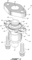
Fig. 1 is an isometric view of a tube assembly for a gas turbine engine; -
Fig. 2 is an exploded view of the tube assembly and illustrating details of a dual seal arrangement including a self-attachable metal gasket clipped on a 2-bolt flange of a tube fitting; -
Fig. 3 is an isometric view of the self-attachable metal gasket; and -
Fig. 4 is a cross-section taken along line 4-4 ofFig. 3 . -
Fig. 1 illustrates an embodiment of atube assembly 10 comprising atube 12 fluidly and mechanically connected to anengine component 14, such as an engine accessory (e.g., a heat exchanger, a pump, a sensor, etc.) or an engine case of a gas turbine engine. For instance, thetube assembly 10 may be used for providing double sealing to tube-to-boss fittings for oil, fuel, air systems of gas turbine engines. According to some embodiments, thetube assembly 10 is suited for use with stainless steel tubes having an outer diameter (O.D.) up to .375" (e.g., .25" or .375" (6.35mm or 9.525mm)). - Referring to
Figs. 1 and2 , it can be seen that thetube assembly 10 comprises atube fitting 16 having atube flange 18 adapted to be detachably secured, such as by bolting or the like, to acorresponding mounting surface 20 of theengine component 14. Themounting surface 20 can be provided on aboss 22 projecting from an outer surface of theengine component 14. Thetube flange 18 and themounting surface 20 can include pairs of registeringbolt holes 24, 26 (Fig. 2 ) for receivingcorresponding bolts 28. According to the illustrated embodiment, the flange connection is a 2-bolt flange connection. However, it is understood that a different bolt pattern could be provided. In addition, it is understood that other suitable fasteners could be used to detachably secure thetube flange 18 to themounting surface 20 of theengine component 14. For instance, threaded studs could extend from themounting surface 20 for engagement in corresponding holes in thetube flange 18 and nuts could be installed on the threaded studs and torqued to securely press thetube flange 18 against themounting surface 20. - Referring to
Fig. 2 , it can be appreciated that thetube assembly 10 has a double or dual seal arrangement including afirst seal 30 and asecond seal 32 disposed in series to prevent possible leaks at the exemplified tube-to-boss fitting connection. According to some embodiments, thefirst seal 30 is provided in the form of an O-ring to provide sealing at a tube-to-bore interface between the inner diameter surface afluid port 34 of theengine component 14 and an outer diameter surface of atubular end portion 36 of thetube fitting 16. The O-ring can be provided in the form of a so-called piloted O-Ring. According to some embodiments, the O-ring is mounted in an annular groove defined in the outer diameter surface of thetubular end portion 36 of thetube fitting 16 prior to engaging thetubular end portion 36 in thefluid port 34 of theengine component 14. Thefirst seal 30 may be damaged at installation or during engine running and a possible leak can develop. Thesecond seal 32 is added to provide sealing if the first seal is leaking. Thesecond seal 32 is configured to provide sealing at the flange interface between thetube flange 18 and themounting surface 20 of theengine component 14. As will be seen hereinafter, thesecond seal 32 may be provided in the form of a self-attaching metal gasket adapted to be manually pre-installed (without any tools) in a single predetermined orientation/position on thetube flange 18 of thetube fitting 16. -
Fig. 3 illustrates an embodiment of the metal gasket. The metal gasket has a flatsheet metal body 38 having atube facing side 40 and an enginecomponent facing side 42 opposite to thetube facing side 40. Thesheet metal body 38 has a shape and a surface area corresponding to the shape and surface area of thetube flange 18.Corrugations tube facing side 40. Thecorrugations sheet metal body 38. According to the some embodiments, thecorrugations annular corrugation 46a encircling acentral hole 48 defined in thesheet metal body 38 to receive thetubular end portion 36 of thetube fitting 16. Thecentral hole 48 and theannular corrugation 46a are concentric. Thecorrugations straight corrugations 46b disposed outside of theannular corrugation 46a. First andsecond bolt holes 50 are disposed between the linear corrugations of the first pair and the second pair oflinear corrugations 46b, respectively. Thebolt holes 50 are disposed for registry with the associatedbolt holes 24 in thetube flange 18 on opposed sides of thetubular end portion 36 of thetube fitting 16. According to some embodiments, thelinear corrugations 46b extend from the peripheral edge of thesheet metal body 38 inboard towards theannular corrugation 46a. The length oflinear corrugations 46b may be selected to fully span thebolt holes 50 they are neighboring. The inner end of thelinear corrugations 46b is however spaced from theannular corrugation 46a in order not to interfere with the deformation of theannular corrugation 46a when thebolts 28 are torqued to compress the metal gasket between thetube flange 18 and the mountingsurface 20 of theengine component 14. As shown inFigs. 3 and4 , theannular corrugation 46a and thelinear corrugations 46b can have different shapes and/or cross-section profiles to provide for different deformation behavior when clamped between thetube flange 18 and the mountingsurface 20 of theengine component 14. For instance, theannular corrugation 46a may be shaped and configured so as to be subject to elastic deformation only when thebolts 28 are torqued to a pre-calibrated installation torque. On the other hand, thelinear corrugations 46b may be shaped and configured to be subject to elastic and/or plastic deformation under the same pre-calibrated torque. According to another embodiment, the profile of theannular corrugation 46a may be designed to provide for a plastic deformation of theannular corrugation 46a under that same pre-calibrated torque. Various combinations of the corrugation profiles are contemplated. - The metal gasket further comprises a plurality of
tabs 52 distributed along the perimeter of thesheet metal body 38. Like thecorrugations tabs 52 project out from the plane of thesheet metal body 38 on the tube facing side 40 (i.e. thetabs 52 and thecorrugations Figs. 1 and2 , thetabs 52 are operable to tightly fit around and resiliently grasp the contour orperipheral wall 54 of thetube flange 18. In this way, the metal gasket can be readily snapped in position on thetube flange 18 without the use of any tool. Thetabs 52 are spring loaded so as to exert a retention force against theperipheral wall 54 of thetube flange 18, thereby providing for a self-attaching metal gasket. This is particularly useful for use in difficult access areas. Thetabs 52 ensure that the metal gasket is properly positioned on thetube flange 18 and prevent the gasket from being inadvertently displaced out of position while thetube flange 18 is bolted to theengine component 14. Thetabs 52 centralize the metal gasket on thetube flange 18, thereby providing for a self-positioning gasket. In this way, a tighter fit can be provided for thecentral hole 48 and the bolts holes 50 and as such, a smaller flange "footprint" can be used since the need to accommodate stack-up tolerances is reduced. Accordingly, smaller tube flanges can be used. This translates in weight savings. - The
tabs 52 also act as a mistake-proof feature. Indeed, the presence of thetabs 52 ensures that the metal gasket is installed on thetube flange 18 with thetube facing side 40 of thesheet metal body 38 facing thetube flange 18 that is with thecorrugations tube flange 18. According to some embodiments, the mountingsurface 20 of theengine component 14 can be made of a material that is softer than the materials used for thetube flange 18 and the metal gasket. For instance, theengine component 14 can be made out of aluminum, whereas thetube flange 18 and the metal gasket can be made out of stainless steel. In such instances, it is desirable that the metal gasket be installed with the corrugations facing the harder tube steel material to minimize the risk of scoring/damaging the softer aluminum engine component. Thetabs 52 thus allows to mistakeproof the installation by preventing the metal gasket from being installed upside down with thecorrugations surface 20 of theengine component 14. - The
tabs 52 also provide a visual indication when installed. Indeed, with this feature incorporated the mechanic/assembler will have visual confirmation that thesecond seal 32 is installed. As can be appreciated fromFig. 1 , thetabs 52 are visible from the tube side. Furthermore, in locations where the metal gasket is installed at awkward angles or in downward directions, thetabs 52 will retain the metal gasket in position onto thetube flange 18 during the installation procedure, thereby reducing the risk that the gasket falls off thetube flange 18. - According to some embodiments, the plurality of
tabs 52 includes four tabs distributed along the perimeter of thesheet metal body 38. For instance, according to the illustrated embodiment, thesheet metal body 38 of the gasket has a diamond shape including four straight sides joined by rounded corners, and thetabs 52 are disposed centrally along the straight sides. However, it is understood that thetabs 52 could be positioned at other locations along the straight sides of thesheet metal body 38. It is also understood that more than one tabs could be provided per straight sides. Still referring to the illustrated embodiment, thetabs 52 are disposed around thecentral hole 48 and theannular corrugation 46a. Thetabs 52 can be arranged in diametrically opposed pairs around thecentral hole 48. In addition, as shown inFig. 3 , each pair ofstraight corrugations 46b can be disposed between twoadjacent tabs 52 positioned on opposed side of the major axis of the diamond shapesheet metal body 38. - According to some embodiments, the
tabs 52 extend at right angles from the plane of thesheet metal body 38 of the gasket. However, it is understood that other angles are possible as long as thetabs 52 remain effective for retaining the metal gasket onto thetube flange 18. As shown inFig. 3 , thetabs 52 project further way from the plane of thesheet metal body 38 than thecorrugations tabs 52 have a greater height than that of thecorrugations Fig. 1 , the height or length of thetabs 52 is selected to project beyond theperipheral wall 54 to a location on the top side of thetube flange 18 after the gasket has been snapped into position. Each of thetabs 52 may have a roundedlip 52a formed at a free distal end thereof, therounded lip 52a forming an inwardly facing bump for engagement with thetube flange 18 of thetube fitting 16. As can be seen fromFig. 1 , therounded lips 52a are accessible from the top side of thetube flange 18. - In view of the foregoing, it can be appreciated at least to some embodiments,
tabs 52 provide the possibility to add a self-attaching metal gasket to an existing suitable configuration, without any modifications to the tube or its adjoining interface and related hardware. This way, the probability of a leak is reduced and the overall reliability of the engine may be increased. - According to some embodiments, the thickness of the
sheet metal body 38 is selected to be sufficiently small so as to minimize the stress of the tube resulting from a lost of pre-load after torquing thebolts 28. Because of the plastic and elastic deformations induced in thesheet metal body 38 when compressed between thetube flange 18 and the mountingsurface 20 of theengine component 14, there is a loss of pre-load for thebolts 28. This results in a reduction of the clamping load. The reduction of the clamping load may be reduced to an acceptable level by strategically selecting the thickness of thesheet metal body 38. According to some embodiments, thesheet metal body 38 is made of stainless steel and has a thickness less than 30 thou (0.76mm), preferably between 5 thou (0.13mm) and 20 thou (0.51mm), and more preferably of 7 thou (0.18mm). - According to some embodiments, an anti-friction coating is applied on the
sheet metal body 38. The anti-friction coating can be applied to both thetube facing side 40 and the enginecomponent facing side 42 or to only a selected side of the gasket. Alternatively, the sheet metal body may be entirely coated. - The embodiments described in this document provide non-limiting examples of possible implementations of the present technology. Upon review of the present disclosure, a person of ordinary skill in the art will recognize that changes may be made to the embodiments described herein without departing from the scope of the present technology. For instance, the number and configurations of the tabs could be different. Yet further modifications could be implemented by a person of ordinary skill in the art in view of the present disclosure, which modifications would be within the scope of the present technology.
Claims (12)
- A tube assembly (10) for a gas turbine engine, comprising:a tube (12) having a tube end and a tube flange (18) projecting from the tube end to a peripheral wall (54) circumscribing the tube flange (18);an engine component (14) having a tube mounting surface (20) surrounding a fluid port (34) fluidly connected to the tube (12), the tube end engaged in the fluid port (34) and defining a bore interface therebetween, a flange interface defined between the tube mounting surface (20) and the tube flange (18);a first seal (30) at the bore interface between the tube (12) and the fluid port (34) of the engine component (14);a second seal (32) at the flange interface between the tube flange (18) and the tube mounting surface (20) of the engine component (14), the second seal (32) including a gasket, the gasket having:a sheet metal body (38) having a tube facing side (40) and an engine component facing side (42) opposite to the tube facing side (40);corrugations (46a, 46b) projecting from the tube facing side (40); andtabs (52) distributed along a periphery of the sheet metal body (38), the tabs (52) spring loaded against the peripheral wall (54) of the tube flange (18), the tabs (52) resiliently holding the gasket on the tube flange (18) with the tube facing side (40) of the gasket facing the tube flange (18); andfasteners (28) securing the tube flange (18) to the tube mounting surface (20) of the engine component (14), the fasteners (28) holding the gasket in compression between the tube flange (18) and the tube mounting surface (20).
- The tube assembly (10) according to claim 1, wherein the tabs (52) and the corrugations (46a, 46b) project outwardly from the tube facing side (40) of the sheet metal body (38), and wherein the tabs (52) have a height greater than that of the corrugations (46a, 46b).
- The tube assembly (10) according to claim 1 or 2, wherein the tube flange (18) and the tube mounting surface (20) are respectively made of a first and a second material, the second material of the tube mounting surface (20) being softer that the first material of the tube flange (18), the corrugations (46a, 46b) of the gasket elastically and/or plastically deformed against the tube flange (18).
- The tube assembly (10) according to claim 3, wherein the first material of the tube flange (18) is stainless steel and the second material of the tube mounting surface (20) is aluminium, and wherein the sheet metal body (38) of the gasket is made of stainless steel, the corrugations (46a) deformed against the tube flange (18) by a torque applied to the fasteners.
- The tube assembly (10) according to any preceding claim, wherein the gasket is self-centered on the tube flange (18) by a snap on engagement of the tabs (52) with the peripheral wall (54) of the tube flange (18).
- The tube assembly (10) according to any preceding claim, wherein the sheet metal body (38) has a diamond shape including four straight side edges, and wherein the tabs (52) include one or more tabs on each of the straight side edges.
- The tube assembly (10) according to any preceding claim, wherein the corrugations (46a, 46b) include a central annular corrugation (46a) concentric with a central hole (48) defined in the sheet metal body (38) of the gasket, and a first pair and a second pair of linear corrugations (46b) disposed outside of the central annular corrugation (46a), the sheet metal body (38) having a first bolt hole (50) and a second bolt hole (50) defined therethrough on diametrically opposed sides of the central hole (48), the first bolt hole (50) disposed between the linear corrugations (46b) of the first pair of linear corrugations (46b), the second bolt hole (50) disposed between the linear corrugations (46b) of the second pair of linear corrugations (46b).
- The tube assembly (10) according to any preceding claim, wherein the sheet metal body (38) is made out of stainless steel, and wherein the sheet metal body (38) has a thickness comprised between 5 thou and 20 thou (0.13mm to 0.51 mm).
- The tube assembly (10) according to any preceding claim, wherein the sheet metal body (38) has an anti-friction coating applied over one or more of the tube facing side (40) and the engine component facing side (42).
- The tube assembly (10) according to any preceding claim, wherein the tube flange (18) has a first side facing the engine component (14) and a second opposed side, and wherein the tabs (52) are disposed to fit tightly against the peripheral wall (54) of the tube flange (18) and to project beyond the peripheral wall (54) on the second opposed side of the tube flange (18) after the gasket has been snapped into position on the tube flange (18).
- The tube assembly (10) according to claim 10, wherein each of the tabs (52) has a rounded lip (52a) formed at a free distal end thereof, the rounded lip (52a) accessible from the second opposed side of the tube flange (18).
- The tube assembly (10) according to any preceding claim, wherein the sheet metal body (38) has a thickness of about 7 thou (0.18mm).
Applications Claiming Priority (1)
| Application Number | Priority Date | Filing Date | Title |
|---|---|---|---|
| US18/323,614 US12234776B2 (en) | 2023-05-25 | 2023-05-25 | Double seal arrangement |
Publications (2)
| Publication Number | Publication Date |
|---|---|
| EP4467859A1 true EP4467859A1 (en) | 2024-11-27 |
| EP4467859B1 EP4467859B1 (en) | 2026-03-18 |
Family
ID=91226750
Family Applications (1)
| Application Number | Title | Priority Date | Filing Date |
|---|---|---|---|
| EP24177264.9A Active EP4467859B1 (en) | 2023-05-25 | 2024-05-22 | Double seal arrangement |
Country Status (3)
| Country | Link |
|---|---|
| US (1) | US12234776B2 (en) |
| EP (1) | EP4467859B1 (en) |
| CA (1) | CA3238460A1 (en) |
Families Citing this family (1)
| Publication number | Priority date | Publication date | Assignee | Title |
|---|---|---|---|---|
| US12523175B1 (en) * | 2024-12-18 | 2026-01-13 | Pratt & Whitney Canada Corp. | Flame protection seals for gas turbine engines |
Citations (3)
| Publication number | Priority date | Publication date | Assignee | Title |
|---|---|---|---|---|
| US6386593B1 (en) * | 1999-10-29 | 2002-05-14 | Automotive Fluid Systems, Inc. | Dual-plane seal for fluid-tight conduit connection |
| EP1719945A1 (en) * | 2005-05-03 | 2006-11-08 | Hutchinson | High pressure coupling |
| US20190162337A1 (en) * | 2016-07-29 | 2019-05-30 | Fujikin Incorporated | Pipe joint |
Family Cites Families (13)
| Publication number | Priority date | Publication date | Assignee | Title |
|---|---|---|---|---|
| US1704939A (en) * | 1924-11-03 | 1929-03-12 | Graulock Company | Eccentric bushing |
| US3108818A (en) | 1959-12-14 | 1963-10-29 | Felt Products Mfg Co | Fluid transfer seal for gasket |
| GB1213454A (en) | 1967-01-09 | 1970-11-25 | Corrugated Packing Sheet Metal | Improvements in or relating to sealing means |
| US3738558A (en) * | 1970-09-02 | 1973-06-12 | Felt Products Mfg Co | Thin laminated gasket |
| US3727955A (en) * | 1972-03-22 | 1973-04-17 | E Carter | Semiflexible fluid-tight tube coupling |
| DE2455986C3 (en) | 1974-11-27 | 1979-12-06 | Daimler-Benz Ag, 7000 Stuttgart | Sealing arrangement |
| US4570440A (en) * | 1985-07-02 | 1986-02-18 | Chrysler Corporation | Articulated connector |
| JPH0717884Y2 (en) | 1990-10-25 | 1995-04-26 | 石川ガスケット株式会社 | Gasket temporary fixing device |
| JP2581323B2 (en) * | 1990-12-06 | 1997-02-12 | 富士通株式会社 | How to update reference bits and change bits |
| US5524906A (en) | 1994-07-18 | 1996-06-11 | Mascotech Tubular Products, Inc. | Gasket for exhaust system joint |
| US20120139188A1 (en) * | 2010-12-02 | 2012-06-07 | Dana Automotive Systems Group, Llc | Exhaust Manifold Gasket |
| EP3346168B1 (en) * | 2015-09-03 | 2020-03-11 | NOK Corporation | Gasket |
| US20180328257A1 (en) * | 2018-07-25 | 2018-11-15 | Tenneco Automotive Operating Company Inc. | Joint assembly |
-
2023
- 2023-05-25 US US18/323,614 patent/US12234776B2/en active Active
-
2024
- 2024-05-14 CA CA3238460A patent/CA3238460A1/en active Pending
- 2024-05-22 EP EP24177264.9A patent/EP4467859B1/en active Active
Patent Citations (3)
| Publication number | Priority date | Publication date | Assignee | Title |
|---|---|---|---|---|
| US6386593B1 (en) * | 1999-10-29 | 2002-05-14 | Automotive Fluid Systems, Inc. | Dual-plane seal for fluid-tight conduit connection |
| EP1719945A1 (en) * | 2005-05-03 | 2006-11-08 | Hutchinson | High pressure coupling |
| US20190162337A1 (en) * | 2016-07-29 | 2019-05-30 | Fujikin Incorporated | Pipe joint |
Also Published As
| Publication number | Publication date |
|---|---|
| EP4467859B1 (en) | 2026-03-18 |
| US20240392726A1 (en) | 2024-11-28 |
| CA3238460A1 (en) | 2025-06-25 |
| US12234776B2 (en) | 2025-02-25 |
Similar Documents
| Publication | Publication Date | Title |
|---|---|---|
| US20100059988A1 (en) | Loose flange pipe joint | |
| EP2100069B1 (en) | Coupling with concave bearing surface | |
| JP2538261Y2 (en) | Housing type fitting | |
| US8104773B2 (en) | Block fitting and seal structure | |
| US20030214130A1 (en) | Air conditioning block fitting with two surface sealing | |
| JP7559182B2 (en) | Pipe connection part has a structure to prevent separation | |
| EP4467859B1 (en) | Double seal arrangement | |
| KR940019339A (en) | Piping filter | |
| KR102124473B1 (en) | Metal seal fitting for in-tank transmission oil cooler | |
| CA2307385A1 (en) | Gasket with formable tabs and method | |
| JP2912622B2 (en) | Sending unit seal | |
| EP3428488A1 (en) | Gasket and sealing device | |
| US12486927B2 (en) | Press-fitting connection structure for pipeline and refrigeration device | |
| EP0494801B1 (en) | Internal combustion engine and metallic gasket for use therein | |
| EP0866244B1 (en) | Sealing system for metal gasket and gasket attaching portions | |
| EP2908040B1 (en) | Block fitting for metal seal structures | |
| US6318733B1 (en) | Metal laminate gasket with elastic auxiliary sealing member | |
| US20230147384A1 (en) | Housing type pipe joint | |
| US10066774B2 (en) | Double wall tube fitting with an integrated diagnostic port | |
| JP2573880Y2 (en) | Victory type pipe fittings | |
| JP7812888B2 (en) | Pipe connection prevention structure | |
| CN110715125B (en) | Pipeline switching device and automobile air conditioning system | |
| JP2002257276A (en) | Pipe fittings and annular seal rings used therefor | |
| JP2002235884A (en) | Seismic joints and pipelines | |
| EP0949409A1 (en) | Combination of pipes and gasket for connection thereof |
Legal Events
| Date | Code | Title | Description |
|---|---|---|---|
| PUAI | Public reference made under article 153(3) epc to a published international application that has entered the european phase |
Free format text: ORIGINAL CODE: 0009012 |
|
| STAA | Information on the status of an ep patent application or granted ep patent |
Free format text: STATUS: THE APPLICATION HAS BEEN PUBLISHED |
|
| AK | Designated contracting states |
Kind code of ref document: A1 Designated state(s): AL AT BE BG CH CY CZ DE DK EE ES FI FR GB GR HR HU IE IS IT LI LT LU LV MC ME MK MT NL NO PL PT RO RS SE SI SK SM TR |
|
| STAA | Information on the status of an ep patent application or granted ep patent |
Free format text: STATUS: REQUEST FOR EXAMINATION WAS MADE |
|
| 17P | Request for examination filed |
Effective date: 20250527 |
|
| GRAP | Despatch of communication of intention to grant a patent |
Free format text: ORIGINAL CODE: EPIDOSNIGR1 |
|
| STAA | Information on the status of an ep patent application or granted ep patent |
Free format text: STATUS: GRANT OF PATENT IS INTENDED |
|
| RIC1 | Information provided on ipc code assigned before grant |
Ipc: F16L 19/025 20060101AFI20250919BHEP Ipc: F16L 23/16 20060101ALI20250919BHEP Ipc: F16L 41/08 20060101ALI20250919BHEP |
|
| INTG | Intention to grant announced |
Effective date: 20251006 |
|
| GRAS | Grant fee paid |
Free format text: ORIGINAL CODE: EPIDOSNIGR3 |
|
| GRAA | (expected) grant |
Free format text: ORIGINAL CODE: 0009210 |
|
| STAA | Information on the status of an ep patent application or granted ep patent |
Free format text: STATUS: THE PATENT HAS BEEN GRANTED |
|
| AK | Designated contracting states |
Kind code of ref document: B1 Designated state(s): AL AT BE BG CH CY CZ DE DK EE ES FI FR GB GR HR HU IE IS IT LI LT LU LV MC ME MK MT NL NO PL PT RO RS SE SI SK SM TR |
|
| REG | Reference to a national code |
Ref country code: CH Ref legal event code: F10 Free format text: ST27 STATUS EVENT CODE: U-0-0-F10-F00 (AS PROVIDED BY THE NATIONAL OFFICE) Effective date: 20260318 Ref country code: GB Ref legal event code: FG4D |
|
| REG | Reference to a national code |
Ref country code: DE Ref legal event code: R096 Ref document number: 602024003220 Country of ref document: DE |
|
| REG | Reference to a national code |
Ref country code: IE Ref legal event code: FG4D |
|
| PG25 | Lapsed in a contracting state [announced via postgrant information from national office to epo] |
Ref country code: RS Free format text: LAPSE BECAUSE OF FAILURE TO SUBMIT A TRANSLATION OF THE DESCRIPTION OR TO PAY THE FEE WITHIN THE PRESCRIBED TIME-LIMIT Effective date: 20260618 |
|
| PG25 | Lapsed in a contracting state [announced via postgrant information from national office to epo] |
Ref country code: GR Free format text: LAPSE BECAUSE OF FAILURE TO SUBMIT A TRANSLATION OF THE DESCRIPTION OR TO PAY THE FEE WITHIN THE PRESCRIBED TIME-LIMIT Effective date: 20260619 |
|
| REG | Reference to a national code |
Ref country code: LT Ref legal event code: MG9D |
|
| PG25 | Lapsed in a contracting state [announced via postgrant information from national office to epo] |
Ref country code: LT Free format text: LAPSE BECAUSE OF FAILURE TO SUBMIT A TRANSLATION OF THE DESCRIPTION OR TO PAY THE FEE WITHIN THE PRESCRIBED TIME-LIMIT Effective date: 20260318 |
|
| PGFP | Annual fee paid to national office [announced via postgrant information from national office to epo] |
Ref country code: DE Payment date: 20260421 Year of fee payment: 3 |
|
| PG25 | Lapsed in a contracting state [announced via postgrant information from national office to epo] |
Ref country code: NO Free format text: LAPSE BECAUSE OF FAILURE TO SUBMIT A TRANSLATION OF THE DESCRIPTION OR TO PAY THE FEE WITHIN THE PRESCRIBED TIME-LIMIT Effective date: 20260618 |
|
| PG25 | Lapsed in a contracting state [announced via postgrant information from national office to epo] |
Ref country code: SE Free format text: LAPSE BECAUSE OF FAILURE TO SUBMIT A TRANSLATION OF THE DESCRIPTION OR TO PAY THE FEE WITHIN THE PRESCRIBED TIME-LIMIT Effective date: 20260318 Ref country code: FI Free format text: LAPSE BECAUSE OF FAILURE TO SUBMIT A TRANSLATION OF THE DESCRIPTION OR TO PAY THE FEE WITHIN THE PRESCRIBED TIME-LIMIT Effective date: 20260318 |
|
| PG25 | Lapsed in a contracting state [announced via postgrant information from national office to epo] |
Ref country code: HR Free format text: LAPSE BECAUSE OF FAILURE TO SUBMIT A TRANSLATION OF THE DESCRIPTION OR TO PAY THE FEE WITHIN THE PRESCRIBED TIME-LIMIT Effective date: 20260318 |
|
| REG | Reference to a national code |
Ref country code: NL Ref legal event code: MP Effective date: 20260318 |
|
| PGFP | Annual fee paid to national office [announced via postgrant information from national office to epo] |
Ref country code: FR Payment date: 20260421 Year of fee payment: 3 |
|
| PG25 | Lapsed in a contracting state [announced via postgrant information from national office to epo] |
Ref country code: LV Free format text: LAPSE BECAUSE OF FAILURE TO SUBMIT A TRANSLATION OF THE DESCRIPTION OR TO PAY THE FEE WITHIN THE PRESCRIBED TIME-LIMIT Effective date: 20260318 |
|
| PG25 | Lapsed in a contracting state [announced via postgrant information from national office to epo] |
Ref country code: BG Free format text: LAPSE BECAUSE OF FAILURE TO SUBMIT A TRANSLATION OF THE DESCRIPTION OR TO PAY THE FEE WITHIN THE PRESCRIBED TIME-LIMIT Effective date: 20260318 |