EP4467854A1 - Assembly method for flow path switching valve - Google Patents
Assembly method for flow path switching valve Download PDFInfo
- Publication number
- EP4467854A1 EP4467854A1 EP22922040.5A EP22922040A EP4467854A1 EP 4467854 A1 EP4467854 A1 EP 4467854A1 EP 22922040 A EP22922040 A EP 22922040A EP 4467854 A1 EP4467854 A1 EP 4467854A1
- Authority
- EP
- European Patent Office
- Prior art keywords
- flow path
- valve body
- valve
- port
- side wall
- Prior art date
- Legal status (The legal status is an assumption and is not a legal conclusion. Google has not performed a legal analysis and makes no representation as to the accuracy of the status listed.)
- Pending
Links
Images








Classifications
-
- F—MECHANICAL ENGINEERING; LIGHTING; HEATING; WEAPONS; BLASTING
- F16—ENGINEERING ELEMENTS AND UNITS; GENERAL MEASURES FOR PRODUCING AND MAINTAINING EFFECTIVE FUNCTIONING OF MACHINES OR INSTALLATIONS; THERMAL INSULATION IN GENERAL
- F16K—VALVES; TAPS; COCKS; ACTUATING-FLOATS; DEVICES FOR VENTING OR AERATING
- F16K11/00—Multiple-way valves, e.g. mixing valves; Pipe fittings incorporating such valves
- F16K11/02—Multiple-way valves, e.g. mixing valves; Pipe fittings incorporating such valves with all movable sealing faces moving as one unit
- F16K11/08—Multiple-way valves, e.g. mixing valves; Pipe fittings incorporating such valves with all movable sealing faces moving as one unit comprising only taps or cocks
- F16K11/087—Multiple-way valves, e.g. mixing valves; Pipe fittings incorporating such valves with all movable sealing faces moving as one unit comprising only taps or cocks with spherical plug
- F16K11/0873—Multiple-way valves, e.g. mixing valves; Pipe fittings incorporating such valves with all movable sealing faces moving as one unit comprising only taps or cocks with spherical plug the plug being only rotatable around one spindle
- F16K11/0876—Multiple-way valves, e.g. mixing valves; Pipe fittings incorporating such valves with all movable sealing faces moving as one unit comprising only taps or cocks with spherical plug the plug being only rotatable around one spindle one connecting conduit having the same axis as the spindle
-
- F—MECHANICAL ENGINEERING; LIGHTING; HEATING; WEAPONS; BLASTING
- F16—ENGINEERING ELEMENTS AND UNITS; GENERAL MEASURES FOR PRODUCING AND MAINTAINING EFFECTIVE FUNCTIONING OF MACHINES OR INSTALLATIONS; THERMAL INSULATION IN GENERAL
- F16K—VALVES; TAPS; COCKS; ACTUATING-FLOATS; DEVICES FOR VENTING OR AERATING
- F16K27/00—Construction of housing; Use of materials therefor
- F16K27/06—Construction of housing; Use of materials therefor of taps or cocks
- F16K27/067—Construction of housing; Use of materials therefor of taps or cocks with spherical plugs
-
- F—MECHANICAL ENGINEERING; LIGHTING; HEATING; WEAPONS; BLASTING
- F16—ENGINEERING ELEMENTS AND UNITS; GENERAL MEASURES FOR PRODUCING AND MAINTAINING EFFECTIVE FUNCTIONING OF MACHINES OR INSTALLATIONS; THERMAL INSULATION IN GENERAL
- F16K—VALVES; TAPS; COCKS; ACTUATING-FLOATS; DEVICES FOR VENTING OR AERATING
- F16K5/00—Plug valves; Taps or cocks comprising only cut-off apparatus having at least one of the sealing faces shaped as a more or less complete surface of a solid of revolution, the opening and closing movement being predominantly rotary
- F16K5/06—Plug valves; Taps or cocks comprising only cut-off apparatus having at least one of the sealing faces shaped as a more or less complete surface of a solid of revolution, the opening and closing movement being predominantly rotary with plugs having spherical surfaces; Packings therefor
- F16K5/0626—Easy mounting or dismounting means
- F16K5/0636—Easy mounting or dismounting means the spherical plug being insertable from the top of the housing
Definitions
- the present disclosure relates to a method of assembling a flow path switching valve.
- a switching valve described in Japanese Patent Application Laid-Open ( JP-A) No. 2016-138626 includes a valve case having a valve chamber and having a plurality of opening holes communicating with the outside from the valve chamber, a ball-shaped valve body having a flow path selectively communicating with the opening hole and accommodated in the valve chamber, a plurality of valve covers having an outflow/inflow port communicating with the opening hole and attached to the valve case, a drive source for rotationally driving the valve body, a valve shaft, a sliding material disposed between the valve body and the valve cover and in sliding contact with the valve body when the valve body is rotationally driven and making the plurality of opening holes non-communicating with each other, and an elastic member for pressing the sliding material against the valve body.
- a flow path switching valve includes a valve main body in which a valve chamber is formed, a spherical valve body disposed in the valve chamber, and an annular sealing portion disposed in the valve chamber. Specifically, a flow path port through which a fluid passes is formed in each of the plurality of side walls constituting the valve main body. The annular sealing portion is disposed so as to surround the flow path port. The annular sealing portion is in contact with an outer surface of the valve body to seal between the outer surface of the valve body and the side wall of the valve main body.
- valve main body has been divided. For example, three side walls in which the flow path ports are formed are divided into one portion including one side wall and the other portion including two side walls. Then, in a state in which the valve body and all the sealing portions were disposed in the valve chamber, one portion and the other portion divided in the valve main body were fused.
- a relative positional variation occurs between one portion and the other portion in the valve main body, so that a distance between the flow path port formed in the side wall of the valve main body and the outer surface of the valve body also varies.
- valve body and the sealing portion in the valve chamber of the valve main body in which the side wall in which the flow path port is formed is not divided.
- a unit in which the sealing portion and the valve body are combined in advance needs to be disposed in the valve chamber. Therefore, the work is difficult.
- An object of the disclosure is to provide a method of assembling a flow path switching valve capable of easily disposing a valve body and a sealing portion in a valve chamber of a valve main body in which a side wall in which a flow path port is formed is not divided.
- a method of assembling a flow path switching valve including a valve main body, a valve chamber having one end opened being formed inside the valve main body, and a flow path port through which a fluid passes being formed in each of three side walls of the valve chamber, a valve body that is rotatably disposed in the valve chamber, that has a cavity formed inside the valve body, that has a spherical outer surface, that has a flat portion formed in a portion facing a bottom portion of the valve chamber, and that has a flow hole through which a fluid flowing into the cavity or flowing out from the cavity passes and which is formed in the outer surface, three sealing portions that each have an annular shape, that are each disposed so as to surround the flow path port, and that each come into contact with the outer surface to seal between the outer surface and a side wall, a cover that closes an opening port of the valve chamber, and a gap formed between the flat portion of the valve body and the side wall of the valve main body so that the sealing portion is
- the triangular prism-shaped valve chamber with one end opened is formed inside.
- the flow path port through which the fluid from the valve chamber passes is formed in each of the three side walls constituting the valve chamber.
- the gap into which the sealing portion is inserted is formed between the flat portion and the side wall. Accordingly, by rotating the valve body to cause the flat portion of the valve body to sequentially face the three side walls, the sealing portion is inserted into the valve chamber and disposed around each of the three flow path ports.
- the flat portion of the valve body and the bottom portion constituting the valve chamber are made to face each other by rotating the valve body in a state in which the sealing portions are disposed.
- valve body and the sealing portion can be easily disposed in the valve chamber of the valve main body in which the side wall in which the flow path port is formed is not divided.
- a triangular prism-shaped valve chamber having one end opened is formed inside.
- the flow path port through which the fluid from the valve chamber passes is formed in each of the three side walls constituting the valve chamber.
- the gap into which the sealing portion is inserted is formed between the flat portion and the side wall. Accordingly, by rotating the valve body to cause the flat portion of the valve body to sequentially face the three side walls, the sealing portion is inserted into the valve chamber and disposed around each of the three flow path ports.
- the flat portion of the valve body and the bottom portion constituting the valve chamber are made to face each other by rotating the valve body in a state in which the sealing portions are disposed.
- a step of rotating the valve body to cause the flow hole of the valve body and any one of the flow path ports to face each other is provided between the step of disposing the third sealing portion so as to surround the third flow path port through the opening port and the step of rotating the valve body so that the flat portion and the bottom portion face each other, and in the step of rotating the valve body so that the flat portion and the bottom portion face each other, a rod-shaped jig is inserted into the valve chamber from the flow path port, a distal end of the jig engages with the valve body through the flow path port, and the valve body is rotated by rotating the jig.
- the valve body is rotated to cause the flow hole of the valve body and any one of the flow path ports to face each other. Then, the rod-shaped jig is inserted into the valve chamber from the flow path port, the distal end of the jig is engaged with the valve body, and the valve body is rotated by rotating the jig.
- the valve body can be easily rotated even in a state in which the valve body and the three sealing portions are disposed in the valve chamber.
- the step of disposing the first sealing portion so as to surround the first flow path port after the step of disposing the first sealing portion so as to surround the first flow path port, the step of disposing the valve body so that the side wall on which the first flow path port is formed and the flat portion face each other is performed.
- the valve body after the step of disposing the first sealing portion so as to surround the first flow path port, the valve body is disposed so that the side wall on which the first flow path port is formed and the flat portion face each other.
- the valve body can be disposed without being conscious of forming the gap into which the sealing portion is inserted between the side wall on which the first flow path port is formed and the flat portion, that is, without causing a burden in the step of forming the gap.
- a valve body and a sealing portion can be easily disposed in a valve chamber of a valve main body in which a side wall in which a flow path port is formed is not divided.
- An example of a method of assembling a flow path switching valve according to an embodiment of the disclosure will be described with reference to Figs. 1 to 17 .
- An arrow H in each drawing indicates a component vertical direction
- an arrow W indicates a component width direction
- an arrow D indicates a component depth direction.
- the component vertical direction, the component width direction, and the component depth direction are orthogonal to each other.
- the component vertical direction, the component width direction, and the component depth direction in the disclosure may be different from a direction of a use state of the flow path switching valve.
- the flow path switching valve 10 is, for example, a rotary four-way valve that switches a flow path of liquid, which is an example of fluid flowing in an engine room of an automobile, in multiple directions.
- the flow path switching valve 10 includes a valve main body 20, a valve body 50, a sealing portion 70, a cover 80, a stem 84, and a drive unit 86.
- the valve body 50 may be referred to as a valve or a ball valve body.
- the valve main body 20 is integrally formed using a resin material.
- the valve main body 20 is formed using polyphenylene sulfide (PPS) as an example.
- the valve main body 20 includes a box-shaped base portion 22 opened upward in the component vertical direction, three outflow pipes 36 protruding outward from the base portion 22, and one inflow pipe 38 protruding downward from the base portion 22.
- the box-shaped base portion 22 has a triangular shape when viewed from above, and has three side walls 24 and a bottom portion 28.
- a valve chamber 22a in which the valve body 50 is disposed and an opening port 22b that opens the valve chamber 22a upward are formed in the base portion 22.
- a triangular prism-shaped valve chamber 22a with one end opened is formed inside the base portion 22.
- the side wall 24 may be referred to as a side plate.
- a plate thickness direction of the bottom portion 28 is a component vertical direction, and three side walls 24 are orthogonal to the bottom portion 28.
- the bottom portion 28 may be referred to as a bottom plate.
- the three side walls 24 in the present embodiment correspond to three side walls in the disclosure.
- the plate thickness direction of one side wall 24 of the three side walls 24 is the component depth direction.
- the side wall 24 in which the plate thickness direction faces the component depth direction may be referred to as a side wall 24a
- the side wall 24 positioned in the clockwise direction with respect to the side wall 24a in a plan view may be referred to as a side wall 24b
- the remaining side wall 24 may be referred to as a side wall 24c.
- the plan view is an arrow view as viewed from above in the component vertical direction.
- a circular flow path port 26 through which the liquid flowing out from the valve chamber 22a passes is formed in the side wall 24.
- the flow path port 26 formed in the side wall 24a may be referred to as a flow path port 26a
- the flow path port 26 formed in the side wall 24b may be referred to as a flow path port 26b
- the flow path port 26 formed in the side wall 24c may be referred to as a flow path port 26c.
- the three flow path ports 26a, 26b, and 26c are disposed in a planar shape.
- being disposed in a planar shape means that center lines L1 of the three flow path ports 26a, 26b, and 26c are disposed in the same plane.
- the flow path port 26a of the present embodiment corresponds to a first flow path port of the disclosure.
- the flow path port 26b of the present embodiment corresponds to a second flow path port of the disclosure.
- the flow path port 26c of the present embodiment corresponds to a third flow path port of the disclosure.
- sandwiching angles of the center lines L1 of the adjacent flow path ports 26 are all the same, and are set to 120 [degrees].
- the similar angle means substantially the same angle.
- the bottom portion 28 has a triangular shape in a plan view, and a circular inflow port 30 through which liquid flowing into the valve chamber 22a passes is formed in the bottom portion 28.
- a center line L2 of the circular inflow port 30 extends in the component vertical direction, and overlaps an intersection of the three center lines L1 in a plan view as illustrated in Fig. 2C .
- the valve body 50 rotates about the center line L2 as a rotation center (that is, an axial center).
- a plurality of plate-shaped restricting portions 32 for positioning the sealing portion 70 (see Fig. 1 ) disposed in the valve chamber 22a is formed in the bottom portion 28.
- a pair of the restricting portions 32 is formed between the flow path ports 26 in a plan view. Specifically, the restricting portion 32 protrudes from the bottom portion 28 and the side wall 24 to the valve chamber 22a and extends in the component vertical direction. The pair of restricting portions 32 sandwiches the sealing portion 70 to position the sealing portion 70.
- a plurality of plate-shaped support portions 34 that support the valve body 50 (see Fig. 1 ) disposed in the valve chamber 22a from below is formed in the bottom portion 28.
- the plurality of support portions 34 are provided at apex portions of the triangular bottom portion 28.
- the support portion 34 protrudes from the bottom portion 28 to the valve chamber 22a, and the support portion 34 is formed with a support surface 34a facing upward.
- the support surface 34a is a curved surface.
- the outflow pipe 36 has a tubular shape, and as illustrated in Figs. 2A , 2B , and 2C , protrudes outward from the side wall 24 of the base portion 22 and extends in a direction orthogonal to the component vertical direction. Then, the liquid flowing out of the valve chamber 22a through the flow path port 26 passes through the outflow pipe 36.
- the outflow pipe 36 protruding from the side wall 24a to the outside may be referred to as an outflow pipe 36a
- the outflow pipe 36 protruding from the side wall 24b to the outside may be referred to as an outflow pipe 36b
- the outflow pipe 36 protruding from the side wall 24c to the outside may be referred to as an outflow pipe 36c.
- the inflow pipe 38 has a tubular shape, and as illustrated in Figs. 2A and 2B , protrudes outward from the bottom portion 28 of the base portion 22 and extends downward in the component vertical direction. The fluid flowing through the inflow pipe 38 flows into the valve chamber 22a through the inflow port 30.
- the valve body 50 has a spherical shape, and a cavity 50a is formed therein.
- Fig. 3 illustrates the valve body 50 viewed from each direction.
- the valve body 50 viewed from the front side orthogonal to the component vertical direction is referred to as a valve body 50-A
- the valve body 50 viewed from above in the component vertical direction is referred to as a valve body 50-B
- the valve body 50 viewed from below in the component vertical direction is referred to as a valve body 50-C.
- the upper surface portion 52 and the lower surface portion 54 are circular, and the lower surface portion 54 is larger than the upper surface portion 52.
- An outer surface 50b of the valve body 50 sandwiched between the upper surface portion 52 and the lower surface portion 54 is spherical.
- the support surface 34a (see Fig. 2B ) of the support portion 34 described above is a curved surface along the outer surface of the valve body 50. All the spherical portions of the outer surface 50b of the valve body 50 need not have a spherical surface, and a portion sliding on another member may be spherical (that is, the spherical surface).
- a recessed portion 52a having a rectangular shape when viewed from above is formed in the upper surface portion 52.
- a circular inflow hole 54a communicating with the cavity 50a and centered on the center line L2 (see Fig. 2C ) is formed.
- the inflow hole 54a has a circular shape centered on the center line L2.
- the inflow hole 54a faces the inflow port 30 (see Fig. 2B ) of the valve main body 20 in the component vertical direction in the use state of the flow path switching valve 10.
- the lower surface portion 54 where the inflow hole 54a is formed faces the bottom portion 28 where the inflow port 30 of the valve main body 20 is formed in the component vertical direction in the use state of the flow path switching valve 10.
- the sealing portion 70 includes a seat 72 and an O-ring 76.
- the seat 72 is integrally formed using a resin material.
- the seat 72 is formed using polytetrafluoroethylene (PTFE), for example.
- the seat 72 has an annular shape, and surrounds the flow path port 26 in a state of being disposed in the valve chamber 22a (see Figs. 8A and 8B ).
- a part of the O-ring 76 is inserted into the recessed portion 74 of the seat 72.
- the O-ring 76 comes into contact with the side wall 24 of the valve main body 20 and is elastically deformed in a state in which the seat 72 is disposed in the valve chamber 22a.
- the outer surface 50b of the rotating valve body 50 covers the entire flow path port 26b and the entire flow path port 26c.
- the outer surface 50b of the valve body 50 comes into contact with the entire circumference of the tapered surface 72b of the seat 72 in the sealing portion 70 disposed so as to surround the flow path port 26b and the entire circumference of the tapered surface 72b of the seat 72 in the sealing portion 70 disposed so as to surround the flow path port 26c.
- a central angle that is, central angle k2 illustrated in Fig. 5
- a central angle that is, central angle k3 illustrated in Fig. 5
- a central angle from a point on one end of one tapered surface 72b of the seat 72 to a point on one end of the other tapered surface 72b is 155 [degrees].
- a central angle that is, central angle k4 illustrated in Fig. 5
- from the point at the other end of one tapered surface 72b of seat 72 to the point at the other end of the other tapered surface 72b is 176 [degrees].
- the cover 80 has a through hole 80a through which the stem 84 passes, and three cylindrical portions 82 for attaching the drive unit 86 to the cover 80.
- a screw portion of a screw 90 used for attaching the drive unit 86 to the cover 80 meshes with an inner peripheral surface of the cylindrical portion 82.
- the upper surface 82a of the cylindrical portion 82 has a protruding conical shape.
- the cover 80 closes the opening port 22b of the valve main body 20 and is fused to the valve main body 20. As a result, the valve chamber 22a is closed.
- the stem 84 extends in the component vertical direction and passes through a through hole 80a formed in the cover 80 (see Fig. 6 ).
- a fitting portion 84a to be fitted into a recessed portion 52a formed in the upper surface portion 52 of the valve body 50 is formed.
- a gear portion 84b to which the driving force of the motor included in the drive unit 86 is transmitted is formed in a portion opposite to the fitting portion 84a.
- An O-ring 85 that seals between the stem 84 and the through hole 80a of the cover 80 is attached to the stem.
- the drive unit 86 is provided with a motor inside the drive unit 86. As illustrated in Fig. 1 , the drive unit 86 is attached to the cover 80 from above the cover 80. The drive unit 86 is formed with three cylindrical portions 88 for attaching the drive unit 86 to the cover 80. The screw 90 used for attaching the drive unit 86 to the cover 80 is inserted into a circular hole formed in the cylindrical portion 88. As illustrated in Figs. 7A and 7B , a lower surface 88a of the cylindrical portion 88 has a recessed conical shape so that an upper surface 82a of the cylindrical portion 82 is fitted.
- the valve main body 20 is placed on a jig so that the opening port 22b of the valve main body 20 faces upward.
- the sealing portion 70 is disposed in the valve chamber 22a through the opening port 22b.
- the sealing portion 70 is positioned by the restricting portion 32 and is disposed so as to surround the flow path port 26a.
- the valve body 50 is disposed in the valve chamber 22a through the opening port 22b. Specifically, the valve body 50 is supported by the support portion 34 (see Fig. 2B ), and is disposed so that the lower surface portion 54 of the valve body 50 faces the side wall 24a. That is, the valve body 50 is disposed in a state of being inclined by 90 [degrees] with respect to the position of the valve body 50 in the use state of the flow path switching valve 10. In this state, the flow hole 50c of the valve body 50 faces one side (that is, the right side illustrated in Fig. 9A ) in the component width direction.
- the valve body 50 is rotated about the center line L2. Specifically, the valve body 50 is rotated so that the lower surface portion 54 of the valve body 50 faces the side wall 24b. As a result, a gap into which the sealing portion 70 is inserted is formed between the lower surface portion 54 of the valve body 50 and the side wall 24b. In this regard, when the valve body 50 is rotated, the outer surface 50b of the valve body 50 comes into contact with the tapered surface 72b (see Fig. 5B ) of the seat 72 in the sealing portion 70 disposed so as to surround the flow path port 26a.
- the sealing portion 70 is disposed in the valve chamber 22a through the opening port 22b. Specifically, the sealing portion 70 is positioned by the restricting portion 32 and is disposed so as to surround the flow path port 26b.
- the valve body 50 is rotated about the center line L2. Specifically, the valve body 50 is rotated so that the lower surface portion 54 of the valve body 50 faces the side wall 24c. As a result, the gap into which the sealing portion 70 is inserted is formed between the lower surface portion 54 of the valve body 50 and the side wall 24c. In this regard, when the valve body 50 is rotated, the outer surface 50b of the valve body 50 comes into contact with the tapered surface 72b (see Fig. 5B ) of the seat 72 in the sealing portion 70 disposed so as to surround the flow path port 26b.
- the sealing portion 70 is disposed in the valve chamber 22a through the opening port 22b. Specifically, the sealing portion 70 is positioned by the restricting portion 32 and is disposed so as to surround the flow path port 26c.
- valve body 50 is rotated about the center line L2. Specifically, the valve body 50 is rotated so that the flow hole 50c of the valve body 50 faces the flow path port 26a.
- the valve body 50 is rotated. Specifically, the rod-shaped jig 92 is inserted into the cavity 50a of the valve body 50 through the outflow pipe 36a and the flow path port 26a. Then, the distal end of the jig 92 is inserted into a recessed portion (not illustrated) formed in a wall surface constituting the cavity 50a. The distal end of the jig 92 is engaged with the valve body 50.
- valve body 50 By rotating the jig 92 in this state, the valve body 50 is rotated so that the upper surface portion 52 of the valve body 50 faces upward. Accordingly, the valve body 50 is disposed at the position of the flow path switching valve 10 in the use state.
- the fitting portion 84a of the stem 84 is fitted into the recessed portion 52a of the upper surface portion 52 of the valve body 50.
- the stem 84 is inserted into the through hole 80a of the cover 80.
- the cover 80 closes the opening port 22b of the valve main body 20 and is fused to the valve main body 20. As a result, the valve chamber 22a is closed.
- the drive unit 86 is attached to the cover 80. Specifically, as illustrated in Figs. 7A and 7B , three screws 90 are passed through the cylindrical portion 88, and the screws 90 are each tightened into the cylindrical portion 82. Thus, the drive unit 86 is attached to the cover 80. In this state, the gear portion 84b of the stem 84 meshes with the output shaft of the drive unit 86.
- the outer surface 50b of the rotating valve body 50 covers the entire flow path port 26b.
- the outer surface 50b of the valve body 50 comes into contact with the entire circumference of the tapered surface 72b of the seat 72 in the sealing portion 70 disposed so as to surround the flow path port 26b.
- the outer surface 50b of the valve body 50 comes into contact with the entire circumference (that is, the entire circumference of the tapered surface 72b of the sealing portion 70) of the sealing portion 70 disposed so as to surround the flow path port 26b.
- the outer surface 50b of the valve body 50 is not in contact with the entire circumference of the sealing portion 70 disposed so as to surround the flow path port 26a and the entire circumference of the sealing portion 70 disposed so as to surround the flow path port 26c. Therefore, the liquid flowing into the valve chamber 22a from the inflow port 30 flows out from the flow path port 26a and the flow path port 26c.
- the drive unit 86 rotates the valve body 50 disposed in the valve chamber 22a around the center line L2 via the stem 84, so that the outer surface 50b of the valve body 50 covers the entire flow path port 26a. As a result, the outer surface 50b of the valve body 50 comes into contact with the entire circumference of the sealing portion 70 disposed so as to surround the flow path port 26a. The flow path port 26a is closed by the outer surface 50b.
Landscapes
- Engineering & Computer Science (AREA)
- General Engineering & Computer Science (AREA)
- Mechanical Engineering (AREA)
- Multiple-Way Valves (AREA)
Abstract

Description
- The present disclosure relates to a method of assembling a flow path switching valve.
- A switching valve described in Japanese Patent Application Laid-Open (
JP-A) No. 2016-138626 - A flow path switching valve includes a valve main body in which a valve chamber is formed, a spherical valve body disposed in the valve chamber, and an annular sealing portion disposed in the valve chamber. Specifically, a flow path port through which a fluid passes is formed in each of the plurality of side walls constituting the valve main body. The annular sealing portion is disposed so as to surround the flow path port. The annular sealing portion is in contact with an outer surface of the valve body to seal between the outer surface of the valve body and the side wall of the valve main body.
- Conventionally, in a state in which the valve body is disposed in the valve chamber, an operator cannot dispose the sealing portion in the valve chamber. In a state in which all the sealing portions are disposed in the valve chamber, the operator cannot dispose the valve body in the valve chamber. Therefore, the valve main body has been divided. For example, three side walls in which the flow path ports are formed are divided into one portion including one side wall and the other portion including two side walls. Then, in a state in which the valve body and all the sealing portions were disposed in the valve chamber, one portion and the other portion divided in the valve main body were fused.
- In such a configuration, a relative positional variation occurs between one portion and the other portion in the valve main body, so that a distance between the flow path port formed in the side wall of the valve main body and the outer surface of the valve body also varies.
- Therefore, it is desirable to dispose the valve body and the sealing portion in the valve chamber of the valve main body in which the side wall in which the flow path port is formed is not divided. However, for such a configuration, a unit in which the sealing portion and the valve body are combined in advance needs to be disposed in the valve chamber. Therefore, the work is difficult.
- An object of the disclosure is to provide a method of assembling a flow path switching valve capable of easily disposing a valve body and a sealing portion in a valve chamber of a valve main body in which a side wall in which a flow path port is formed is not divided. Solution to Problem
- According to a first aspect of the disclosure, there is provided a method of assembling a flow path switching valve including a valve main body, a valve chamber having one end opened being formed inside the valve main body, and a flow path port through which a fluid passes being formed in each of three side walls of the valve chamber, a valve body that is rotatably disposed in the valve chamber, that has a cavity formed inside the valve body, that has a spherical outer surface, that has a flat portion formed in a portion facing a bottom portion of the valve chamber, and that has a flow hole through which a fluid flowing into the cavity or flowing out from the cavity passes and which is formed in the outer surface, three sealing portions that each have an annular shape, that are each disposed so as to surround the flow path port, and that each come into contact with the outer surface to seal between the outer surface and a side wall, a cover that closes an opening port of the valve chamber, and a gap formed between the flat portion of the valve body and the side wall of the valve main body so that the sealing portion is inserted in a state in which the flat portion faces the side wall, the method including: a step of disposing a first sealing portion so as to surround a first flow path port through the opening port; a step of disposing the valve body so that the side wall on which the first flow path port is formed and the flat portion face each other through the opening port; a step of rotating the valve body so that the flat portion and the side wall on which a second flow path port is formed face each other; a step of disposing a second sealing portion so as to surround the second flow path port through the opening port; a step of rotating the valve body so that the flat portion and the side wall on which a third flow path port is formed face each other; a step of disposing a third sealing portion so as to surround the third flow path port through the opening port; a step of rotating the valve body so that the flat portion and the bottom portion face each other; and a step of closing the opening port by using the cover.
- According to the above aspect, in the valve main body of the flow path switching valve assembled by the method of assembling the flow path switching valve, the triangular prism-shaped valve chamber with one end opened is formed inside. The flow path port through which the fluid from the valve chamber passes is formed in each of the three side walls constituting the valve chamber.
- By causing the flat portion of the valve body to face the side wall of the valve main body, the gap into which the sealing portion is inserted is formed between the flat portion and the side wall. Accordingly, by rotating the valve body to cause the flat portion of the valve body to sequentially face the three side walls, the sealing portion is inserted into the valve chamber and disposed around each of the three flow path ports. The flat portion of the valve body and the bottom portion constituting the valve chamber are made to face each other by rotating the valve body in a state in which the sealing portions are disposed.
- As described above, the valve body and the sealing portion can be easily disposed in the valve chamber of the valve main body in which the side wall in which the flow path port is formed is not divided.
- According to a second aspect of the disclosure, there is provided a method of assembling a flow path switching valve including a valve main body, a valve chamber having one end opened being formed inside the valve main body, an inflow port through which a fluid passes being formed in a bottom portion of the valve chamber, and a flow path port through which the fluid passes being formed in each of three side walls of the valve chamber, a valve body that is rotatably disposed in the valve chamber, that has a cavity formed inside the valve body, that has a spherical outer surface, that has a flat portion formed in a portion facing the bottom portion, and that has a flow hole through which a fluid flowing into the cavity or flowing out from the cavity passes and which is formed in the outer surface, three sealing portions that each have an annular shape, that are each disposed so as to surround the flow path port, and that each come into contact with the outer surface to seal between the outer surface and a side wall, a cover that closes an opening port of the valve chamber, and a gap formed between the flat portion of the valve body and the side wall of the valve main body so that the sealing portion is inserted in a state in which the flat portion faces the side wall, the method including: a step of disposing a first sealing portion so as to surround a first flow path port through the opening port; a step of disposing the valve body so that the side wall on which the first flow path port is formed and the flat portion face each other through the opening port; a step of rotating the valve body so that the flat portion and the side wall on which a second flow path port is formed face each other; a step of disposing a second sealing portion so as to surround the second flow path port through the opening port; a step of rotating the valve body so that the flat portion and the side wall on which a third flow path port is formed face each other; a step of disposing a third sealing portion so as to surround the third flow path port through the opening port; a step of rotating the valve body so that the flat portion and the bottom portion face each other; and a step of closing the opening port by using the cover.
- According to the above aspect, in the valve main body of the flow path switching valve assembled by the method of assembling the flow path switching valve, a triangular prism-shaped valve chamber having one end opened is formed inside. The flow path port through which the fluid from the valve chamber passes is formed in each of the three side walls constituting the valve chamber.
- By causing the flat portion of the valve body to face the side wall of the valve main body, the gap into which the sealing portion is inserted is formed between the flat portion and the side wall. Accordingly, by rotating the valve body to cause the flat portion of the valve body to sequentially face the three side walls, the sealing portion is inserted into the valve chamber and disposed around each of the three flow path ports. The flat portion of the valve body and the bottom portion constituting the valve chamber are made to face each other by rotating the valve body in a state in which the sealing portions are disposed.
- As described above, the valve body and the sealing portion can be easily disposed in the valve chamber of the valve main body in which the side wall in which the flow path port is formed is not divided.
- In the method of assembling a flow path switching valve according to a third aspect of the disclosure, in the method of assembling a flow path switching valve according to the first or second aspect, a step of rotating the valve body to cause the flow hole of the valve body and any one of the flow path ports to face each other is provided between the step of disposing the third sealing portion so as to surround the third flow path port through the opening port and the step of rotating the valve body so that the flat portion and the bottom portion face each other, and in the step of rotating the valve body so that the flat portion and the bottom portion face each other, a rod-shaped jig is inserted into the valve chamber from the flow path port, a distal end of the jig engages with the valve body through the flow path port, and the valve body is rotated by rotating the jig.
- According to the above aspect, the valve body is rotated to cause the flow hole of the valve body and any one of the flow path ports to face each other. Then, the rod-shaped jig is inserted into the valve chamber from the flow path port, the distal end of the jig is engaged with the valve body, and the valve body is rotated by rotating the jig.
- As described above, by using the rod-shaped jig, the valve body can be easily rotated even in a state in which the valve body and the three sealing portions are disposed in the valve chamber.
- In the method of assembling a flow path switching valve according to a fourth aspect of the disclosure, in the method of assembling the flow path switching valve according to any one of the first to third aspects, after the step of disposing the first sealing portion so as to surround the first flow path port, the step of disposing the valve body so that the side wall on which the first flow path port is formed and the flat portion face each other is performed.
- According to the above aspect, after the step of disposing the first sealing portion so as to surround the first flow path port, the valve body is disposed so that the side wall on which the first flow path port is formed and the flat portion face each other. As a result, the valve body can be disposed without being conscious of forming the gap into which the sealing portion is inserted between the side wall on which the first flow path port is formed and the flat portion, that is, without causing a burden in the step of forming the gap.
- According to the disclosure, a valve body and a sealing portion can be easily disposed in a valve chamber of a valve main body in which a side wall in which a flow path port is formed is not divided.
-
-
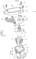
Fig. 1 is an exploded perspective view illustrating a flow path switching valve used in a method of assembling a flow path switching valve according to an embodiment of the disclosure. -
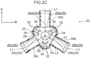
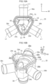
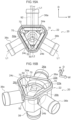
Fig. 2A is a perspective view illustrating a valve main body of the flow path switching valve used in the method of assembling the flow path switching valve according to the embodiment of the disclosure,Fig. 2B is a cross-sectional perspective view illustrating the valve main body of the flow path switching valve according to the embodiment of the disclosure, andFig. 2C is a plan cross-sectional view illustrating the valve main body of the flow path switching valve according to the embodiment of the disclosure. -
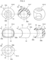
Fig. 3 is a view illustrating a valve body of the flow path switching valve used in the method of assembling the flow path switching valve according to the embodiment of the disclosure. -
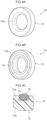
Figs. 4A and 4B are perspective views illustrating a sealing portion of the flow path switching valve used in the method of assembling the flow path switching valve according to the embodiment of the disclosure, andFig. 4C is a cross-sectional view illustrating the sealing portion of the flow path switching valve according to the embodiment of the disclosure. -
Figs. 5A and 5B are cross-sectional views illustrating the valve main body, the sealing portion, and the valve body of the flow path switching valve used in the method of assembling the flow path switching valve according to the embodiment of the disclosure. -
Fig. 6 is a cross-sectional view illustrating the valve main body, the sealing portion, and the valve body of the flow path switching valve used in the method of assembling the flow path switching valve according to the embodiment of the disclosure. -
Fig. 7A is a cross-sectional view illustrating a cover and a drive unit of the flow path switching valve used in the method of assembling the flow path switching valve according to the embodiment of the disclosure, andFig. 7B is an enlarged cross-sectional view illustrating the cover and the drive unit of the flow path switching valve according to the embodiment of the disclosure. -
Fig. 8A is a plan view illustrating the method of assembling the flow path switching valve according to the embodiment of the disclosure in the middle of assembly, andFig. 8B is a perspective view illustrating the flow path switching valve in the middle of assembly. -
Fig. 9A is a plan view illustrating the method of assembling the flow path switching valve according to the embodiment of the disclosure in the middle of assembly, andFig. 9B is a perspective view illustrating the flow path switching valve in the middle of assembly. -
Fig. 10A is a plan view illustrating the method of assembling the flow path switching valve according to the embodiment of the disclosure in the middle of assembly, andFig. 10B is a perspective view illustrating the method in the middle of assembly. -
Fig. 11A is a plan view illustrating the method of assembling the flow path switching valve according to the embodiment of the disclosure in the middle of assembly, andFig. 11B is a perspective view illustrating the method in the middle of assembly. -
Fig. 12A is a plan view illustrating the method of assembling the flow path switching valve according to the embodiment of the disclosure in the middle of assembly, andFig. 12B is a perspective view illustrating the method in the middle of assembly. -
Fig. 13A is a plan view illustrating the method of assembling the flow path switching valve according to the embodiment of the disclosure in the middle of assembly, andFig. 13B is a perspective view illustrating the method in the middle of assembly. -
Fig. 14A is a plan view illustrating the method of assembling the flow path switching valve according to the embodiment of the disclosure in the middle of assembly, andFig. 14B is a perspective view illustrating the method in the middle of assembly. -
Fig. 15A is a plan view illustrating the method of assembling the flow path switching valve according to the embodiment of the disclosure in the middle of assembly, andFig. 15B is a perspective view illustrating the method in the middle of assembly. -
Fig. 16 is a perspective view illustrating the method of assembling the flow path switching valve according to the embodiment of the disclosure, and illustrating the flow path switching valve in the middle of assembly. -
Fig. 17 is a perspective view illustrating the whole of the flow path switching valve assembled by the method of assembling the flow path switching valve according to the embodiment of the disclosure. - An example of a method of assembling a flow path switching valve according to an embodiment of the disclosure will be described with reference to
Figs. 1 to 17 . An arrow H in each drawing indicates a component vertical direction, an arrow W indicates a component width direction, and an arrow D indicates a component depth direction. The component vertical direction, the component width direction, and the component depth direction are orthogonal to each other. The component vertical direction, the component width direction, and the component depth direction in the disclosure may be different from a direction of a use state of the flow path switching valve. - In the following description of the drawings, the same reference numerals or similar reference numerals are assigned to the same portions and similar portions. However, a relationship between a thickness and a plane dimension in the drawings, a ratio of thicknesses of each device and each member, and the like are different from the actual ones. Therefore, specific thicknesses and dimensions should be determined in consideration of the following description. The drawings include portions having different dimensional relationships and ratios. Unless otherwise specified in the specification, the number of each component of the disclosure is not limited to one, and a plurality of components may be present.
- First, a configuration of a flow
path switching valve 10 assembled by a method of assembling the flow path switching valve will be described, and next, the method of assembling the flow path switching valve to assemble the flowpath switching valve 10 will be described. - The flow
path switching valve 10 is, for example, a rotary four-way valve that switches a flow path of liquid, which is an example of fluid flowing in an engine room of an automobile, in multiple directions. - As illustrated in
Fig. 1 , the flowpath switching valve 10 includes a valvemain body 20, avalve body 50, a sealingportion 70, acover 80, astem 84, and adrive unit 86. Thevalve body 50 may be referred to as a valve or a ball valve body. - The valve
main body 20 is integrally formed using a resin material. In the present embodiment, the valvemain body 20 is formed using polyphenylene sulfide (PPS) as an example. - As illustrated in
Fig. 2A , the valvemain body 20 includes a box-shapedbase portion 22 opened upward in the component vertical direction, threeoutflow pipes 36 protruding outward from thebase portion 22, and oneinflow pipe 38 protruding downward from thebase portion 22. - As illustrated in
Figs. 2A ,2B , and2C , the box-shapedbase portion 22 has a triangular shape when viewed from above, and has threeside walls 24 and abottom portion 28. In thebase portion 22, avalve chamber 22a in which thevalve body 50 is disposed and anopening port 22b that opens thevalve chamber 22a upward are formed. In this manner, a triangular prism-shapedvalve chamber 22a with one end opened is formed inside thebase portion 22. Theside wall 24 may be referred to as a side plate. - A plate thickness direction of the
bottom portion 28 is a component vertical direction, and threeside walls 24 are orthogonal to thebottom portion 28. Thebottom portion 28 may be referred to as a bottom plate. - As illustrated in
Figs. 2A ,2B , and2C , threeside walls 24 are provided. The threeside walls 24 in the present embodiment correspond to three side walls in the disclosure. The plate thickness direction of oneside wall 24 of the threeside walls 24 is the component depth direction. Hereinafter, for convenience of description, theside wall 24 in which the plate thickness direction faces the component depth direction may be referred to as aside wall 24a, theside wall 24 positioned in the clockwise direction with respect to theside wall 24a in a plan view may be referred to as aside wall 24b, and the remainingside wall 24 may be referred to as aside wall 24c. In the present embodiment, the plan view is an arrow view as viewed from above in the component vertical direction. - In this regard, a circular
flow path port 26 through which the liquid flowing out from thevalve chamber 22a passes is formed in theside wall 24. Hereinafter, for convenience of description, theflow path port 26 formed in theside wall 24a may be referred to as aflow path port 26a, theflow path port 26 formed in theside wall 24b may be referred to as aflow path port 26b, and theflow path port 26 formed in theside wall 24c may be referred to as aflow path port 26c. - The three
flow path ports flow path ports flow path port 26a of the present embodiment corresponds to a first flow path port of the disclosure. Theflow path port 26b of the present embodiment corresponds to a second flow path port of the disclosure. Theflow path port 26c of the present embodiment corresponds to a third flow path port of the disclosure. - As indicated by a bidirectional arrow kl in
Fig. 2C , in a plan view, sandwiching angles of the center lines L1 of the adjacentflow path ports 26 are all the same, and are set to 120 [degrees]. In the disclosure, the similar angle means substantially the same angle. - As illustrated in
Figs. 2B and2C , thebottom portion 28 has a triangular shape in a plan view, and acircular inflow port 30 through which liquid flowing into thevalve chamber 22a passes is formed in thebottom portion 28. A center line L2 of thecircular inflow port 30 extends in the component vertical direction, and overlaps an intersection of the three center lines L1 in a plan view as illustrated inFig. 2C . Although described in detail later, the valve body 50 (seeFig. 1 ) rotates about the center line L2 as a rotation center (that is, an axial center). - A plurality of plate-shaped restricting
portions 32 for positioning the sealing portion 70 (seeFig. 1 ) disposed in thevalve chamber 22a is formed in thebottom portion 28. - As illustrated in
Fig. 2C , a pair of the restrictingportions 32 is formed between theflow path ports 26 in a plan view. Specifically, the restrictingportion 32 protrudes from thebottom portion 28 and theside wall 24 to thevalve chamber 22a and extends in the component vertical direction. The pair of restrictingportions 32 sandwiches the sealingportion 70 to position the sealingportion 70. - As illustrated in
Figs. 2B and2C , a plurality of plate-shapedsupport portions 34 that support the valve body 50 (seeFig. 1 ) disposed in thevalve chamber 22a from below is formed in thebottom portion 28. The plurality ofsupport portions 34 are provided at apex portions of thetriangular bottom portion 28. Specifically, thesupport portion 34 protrudes from thebottom portion 28 to thevalve chamber 22a, and thesupport portion 34 is formed with asupport surface 34a facing upward. Thesupport surface 34a is a curved surface. - The
outflow pipe 36 has a tubular shape, and as illustrated inFigs. 2A ,2B , and2C , protrudes outward from theside wall 24 of thebase portion 22 and extends in a direction orthogonal to the component vertical direction. Then, the liquid flowing out of thevalve chamber 22a through theflow path port 26 passes through theoutflow pipe 36. - Hereinafter, for convenience of description, the
outflow pipe 36 protruding from theside wall 24a to the outside may be referred to as anoutflow pipe 36a, theoutflow pipe 36 protruding from theside wall 24b to the outside may be referred to as anoutflow pipe 36b, and theoutflow pipe 36 protruding from theside wall 24c to the outside may be referred to as anoutflow pipe 36c. - The
inflow pipe 38 has a tubular shape, and as illustrated inFigs. 2A and2B , protrudes outward from thebottom portion 28 of thebase portion 22 and extends downward in the component vertical direction. The fluid flowing through theinflow pipe 38 flows into thevalve chamber 22a through theinflow port 30. - In the present embodiment, it is described that the fluid flows into the
valve chamber 22a from the inflow pipe 38 (that is, theinflow port 30 of the inlet pipe 38) and flows out from the outflow pipe 36 (that is,outflow pipes outflow pipes other outflow pipes 36 orinflow pipe 38. - The
valve body 50 is integrally formed using a resin material. In the present embodiment, as an example, thevalve body 50 is formed using polyphenylene sulfide (PPS). Thevalve body 50 may be referred to as a valve or a ball valve body. - As illustrated in
Fig. 3 , thevalve body 50 has a spherical shape, and acavity 50a is formed therein.Fig. 3 illustrates thevalve body 50 viewed from each direction. Hereinafter, thevalve body 50 viewed from the front side orthogonal to the component vertical direction is referred to as a valve body 50-A, thevalve body 50 viewed from above in the component vertical direction is referred to as a valve body 50-B, and thevalve body 50 viewed from below in the component vertical direction is referred to as a valve body 50-C. Thevalve body 50 viewed from a side surface side orthogonal to the component vertical direction is referred to as a valve body 50-D, a cross section of thevalve body 50 viewed from the side surface side is referred to as a valve body 50-E, and a cross section of thevalve body 50 viewed from above is referred to as a valve body 50-F. A perspective view of thevalve body 50 is referred to as a valve body 50-G. - As illustrated in the valve body 50-A, the valve body 50-B, and the valve body 50-C, a planar
upper surface portion 52 facing upward is formed in an upper portion of thevalve body 50, and a planarlower surface portion 54 facing downward is formed in a lower portion of thevalve body 50. Thelower surface portion 54 is an example of a flat portion. The lower surface portion 54 (that is, the flat portion) is not necessarily required to have a planar shape, and for example, may have any shape as long as the protruding portion is not formed when thevalve body 50 is viewed from the side. - The
upper surface portion 52 and thelower surface portion 54 are circular, and thelower surface portion 54 is larger than theupper surface portion 52. Anouter surface 50b of thevalve body 50 sandwiched between theupper surface portion 52 and thelower surface portion 54 is spherical. Thesupport surface 34a (seeFig. 2B ) of thesupport portion 34 described above is a curved surface along the outer surface of thevalve body 50. All the spherical portions of theouter surface 50b of thevalve body 50 need not have a spherical surface, and a portion sliding on another member may be spherical (that is, the spherical surface). - A recessed
portion 52a having a rectangular shape when viewed from above is formed in theupper surface portion 52. In thelower surface portion 54, acircular inflow hole 54a communicating with thecavity 50a and centered on the center line L2 (seeFig. 2C ) is formed. Specifically, in the use state of the flowpath switching valve 10, theinflow hole 54a has a circular shape centered on the center line L2. Theinflow hole 54a faces the inflow port 30 (seeFig. 2B ) of the valvemain body 20 in the component vertical direction in the use state of the flowpath switching valve 10. In other words, thelower surface portion 54 where theinflow hole 54a is formed faces thebottom portion 28 where theinflow port 30 of the valvemain body 20 is formed in the component vertical direction in the use state of the flowpath switching valve 10. - As illustrated in the valve body 50-A, the valve body 50-D, the valve body 50-E, and the valve body 50-F, a
flow hole 50c through which liquid flowing into thecavity 50a or flowing out from thecavity 50a passes is formed in theouter surface 50b of thevalve body 50. As illustrated in the valve body 50-F, theflow hole 50c extends in the circumferential direction of thevalve body 50 when viewed from above. - In this configuration, the
valve body 50 supported by thesupport portion 34 rotates about the center line L2 in the use state of the flowpath switching valve 10. That is, thevalve body 50 is rotatably disposed in thevalve chamber 22a. When thevalve body 50 is rotated to cause thelower surface portion 54 of thevalve body 50 and theside wall 24 of thebase portion 22 to face each other, a gap into which the sealingportion 70 can be inserted is formed between thelower surface portion 54 and the side wall 24 (seeFig. 10A ). - As illustrated in
Fig. 1 , three sealingportions 70 each having an annular shape are provided. As illustrated inFigs. 4A, 4B, and 4C , the sealingportion 70 includes aseat 72 and an O-ring 76. - The
seat 72 is integrally formed using a resin material. In the present embodiment, theseat 72 is formed using polytetrafluoroethylene (PTFE), for example. - As illustrated in
Figs. 4A and 4B , theseat 72 has an annular shape, and surrounds theflow path port 26 in a state of being disposed in thevalve chamber 22a (seeFigs. 8A and 8B ). - As illustrated in
Figs. 4C and5B , theseat 72 is formed with a facingsurface 72a facing theside wall 24 of thebase portion 22, and atapered surface 72b inclined with respect to the center line L1 of theflow path port 26 on a side opposite to the facingsurface 72a. An annular recessedportion 74 is formed in the facingsurface 72a. - The O-
ring 76 is formed using an elastic member. In the present embodiment, the O-ring 76 is formed using ethylene propylene diene rubber (EPDM), for example. - As illustrated in
Figs. 4B, 4C , and5B , a part of the O-ring 76 is inserted into the recessedportion 74 of theseat 72. The O-ring 76 comes into contact with theside wall 24 of the valvemain body 20 and is elastically deformed in a state in which theseat 72 is disposed in thevalve chamber 22a. - In this configuration, as illustrated in
Figs. 5A, 5B , and6 , at least a part of theouter surface 50b of thevalve body 50 is in contact with thetapered surfaces 72b of the threeseats 72 regardless of the position of thevalve body 50 that rotates about the center line L2. When the taperedsurface 72b of theseat 72 comes into contact with theouter surface 50b of thevalve body 50, theseat 72 is pushed toward theside wall 24 side, and as a result, the O-ring 76 is compressed. As the O-ring 76 is compressed, a contact pressure between theouter surface 50b of thevalve body 50 and thetapered surface 72b of theseat 72 increases. - As a result, the flow of liquid between the
seat 72 and theside wall 24 is inhibited. The flow of liquid between thetapered surface 72b and theouter surface 50b of thevalve body 50 is inhibited. In other words, the sealingportion 70 comes into contact with theouter surface 50b to seal between theouter surface 50b and theside wall 24. - As illustrated in
Fig. 5A , theouter surface 50b of therotating valve body 50 covers the entireflow path port 26b. In other words, theouter surface 50b of thevalve body 50 comes into contact with the entire circumference of the taperedsurface 72b of theseat 72 in the sealingportion 70 disposed so as to surround theflow path port 26b. - As a result, the liquid flowing into the
valve chamber 22a from theinflow port 30 cannot flow out from theflow path port 26b. In other words, theflow path port 26b is closed. In this manner, theouter surface 50b of therotating valve body 50 is moved to and disposed at a position in contact with the entire circumference of any one of the sealingportions 70. - As illustrated in
Fig. 5B , theouter surface 50b of therotating valve body 50 covers the entireflow path port 26b and the entireflow path port 26c. In other words, theouter surface 50b of thevalve body 50 comes into contact with the entire circumference of the taperedsurface 72b of theseat 72 in the sealingportion 70 disposed so as to surround theflow path port 26b and the entire circumference of the taperedsurface 72b of theseat 72 in the sealingportion 70 disposed so as to surround theflow path port 26c. - As a result, the liquid flowing into the
valve chamber 22a from theinflow port 30 cannot flow out from theflow path port 26b and theflow path port 26c. In other words, theflow path port 26b and theflow path port 26c are closed. In this manner, theouter surface 50b of therotating valve body 50 is moved and disposed at a position in contact with the entire circumference of any two sealingportions 70. - In the present embodiment, as an example, a central angle (that is, central angle k2 illustrated in
Fig. 5 ) from one edge to the other edge of theouter surface 50b of thevalve body 50 is 149 [degrees]. A central angle (that is, central angle k3 illustrated inFig. 5 ) from a point on one end of one taperedsurface 72b of theseat 72 to a point on one end of the othertapered surface 72b is 155 [degrees]. A central angle (that is, central angle k4 illustrated inFig. 5 ) from the point at the other end of one taperedsurface 72b ofseat 72 to the point at the other end of the othertapered surface 72b is 176 [degrees]. - The
cover 80 is integrally formed using a resin material. In the embodiment, cover 80 is formed by using polyphenylene sulfide (PPS), for example. As illustrated inFig. 1 , thecover 80 has a plate shape with the component vertical direction as a plate thickness direction, and closes theopening port 22b of thevalve chamber 22a of the valvemain body 20 from above. - The
cover 80 has a throughhole 80a through which thestem 84 passes, and threecylindrical portions 82 for attaching thedrive unit 86 to thecover 80. A screw portion of ascrew 90 used for attaching thedrive unit 86 to thecover 80 meshes with an inner peripheral surface of thecylindrical portion 82. As illustrated inFigs. 7A and 7B , theupper surface 82a of thecylindrical portion 82 has a protruding conical shape. - In this configuration, the
cover 80 closes theopening port 22b of the valvemain body 20 and is fused to the valvemain body 20. As a result, thevalve chamber 22a is closed. - As illustrated in
Fig. 1 , thestem 84 extends in the component vertical direction and passes through a throughhole 80a formed in the cover 80 (seeFig. 6 ). In a portion of thestem 84 disposed in thevalve chamber 22a, afitting portion 84a to be fitted into a recessedportion 52a formed in theupper surface portion 52 of thevalve body 50 is formed. In this regard, in thestem 84, agear portion 84b to which the driving force of the motor included in thedrive unit 86 is transmitted is formed in a portion opposite to thefitting portion 84a. - An O-
ring 85 that seals between thestem 84 and the throughhole 80a of thecover 80 is attached to the stem. - The
drive unit 86 is provided with a motor inside thedrive unit 86. As illustrated inFig. 1 , thedrive unit 86 is attached to thecover 80 from above thecover 80. Thedrive unit 86 is formed with threecylindrical portions 88 for attaching thedrive unit 86 to thecover 80. Thescrew 90 used for attaching thedrive unit 86 to thecover 80 is inserted into a circular hole formed in thecylindrical portion 88. As illustrated inFigs. 7A and 7B , alower surface 88a of thecylindrical portion 88 has a recessed conical shape so that anupper surface 82a of thecylindrical portion 82 is fitted. - In this configuration, the three
screws 90 are passed through thecylindrical portion 88, and the screw portions of thescrews 90 are respectively tightened into thecylindrical portions 82. Thus, thedrive unit 86 is attached to thecover 80. In this state, thegear portion 84b (seeFig. 1 ) of thestem 84 meshes with the output shaft of thedrive unit 86. - Next, a method of assembling the flow
path switching valve 10 will be described. First, as illustrated inFigs. 8A and 8B , the valvemain body 20 is placed on a jig so that theopening port 22b of the valvemain body 20 faces upward. In this state, the sealingportion 70 is disposed in thevalve chamber 22a through theopening port 22b. Specifically, the sealingportion 70 is positioned by the restrictingportion 32 and is disposed so as to surround theflow path port 26a. - Next, as illustrated in
Figs. 9A and 9B , thevalve body 50 is disposed in thevalve chamber 22a through theopening port 22b. Specifically, thevalve body 50 is supported by the support portion 34 (seeFig. 2B ), and is disposed so that thelower surface portion 54 of thevalve body 50 faces theside wall 24a. That is, thevalve body 50 is disposed in a state of being inclined by 90 [degrees] with respect to the position of thevalve body 50 in the use state of the flowpath switching valve 10. In this state, theflow hole 50c of thevalve body 50 faces one side (that is, the right side illustrated inFig. 9A ) in the component width direction. - Next, as illustrated in
Figs. 10A and 10B , thevalve body 50 is rotated about the center line L2. Specifically, thevalve body 50 is rotated so that thelower surface portion 54 of thevalve body 50 faces theside wall 24b. As a result, a gap into which the sealingportion 70 is inserted is formed between thelower surface portion 54 of thevalve body 50 and theside wall 24b. In this regard, when thevalve body 50 is rotated, theouter surface 50b of thevalve body 50 comes into contact with thetapered surface 72b (seeFig. 5B ) of theseat 72 in the sealingportion 70 disposed so as to surround theflow path port 26a. - Next, as illustrated in
Figs. 11A and 11B , the sealingportion 70 is disposed in thevalve chamber 22a through theopening port 22b. Specifically, the sealingportion 70 is positioned by the restrictingportion 32 and is disposed so as to surround theflow path port 26b. - Next, as illustrated in
Figs. 12A and 12B , thevalve body 50 is rotated about the center line L2. Specifically, thevalve body 50 is rotated so that thelower surface portion 54 of thevalve body 50 faces theside wall 24c. As a result, the gap into which the sealingportion 70 is inserted is formed between thelower surface portion 54 of thevalve body 50 and theside wall 24c. In this regard, when thevalve body 50 is rotated, theouter surface 50b of thevalve body 50 comes into contact with thetapered surface 72b (seeFig. 5B ) of theseat 72 in the sealingportion 70 disposed so as to surround theflow path port 26b. - Next, as illustrated in
Figs. 13A and 13B , the sealingportion 70 is disposed in thevalve chamber 22a through theopening port 22b. Specifically, the sealingportion 70 is positioned by the restrictingportion 32 and is disposed so as to surround theflow path port 26c. - Next, as illustrated in
Figs. 14A and 14B , thevalve body 50 is rotated about the center line L2. Specifically, thevalve body 50 is rotated so that theflow hole 50c of thevalve body 50 faces theflow path port 26a. - Next, as illustrated in
Figs. 15A and 15B , thevalve body 50 is rotated. Specifically, the rod-shapedjig 92 is inserted into thecavity 50a of thevalve body 50 through theoutflow pipe 36a and theflow path port 26a. Then, the distal end of thejig 92 is inserted into a recessed portion (not illustrated) formed in a wall surface constituting thecavity 50a. The distal end of thejig 92 is engaged with thevalve body 50. - By rotating the
jig 92 in this state, thevalve body 50 is rotated so that theupper surface portion 52 of thevalve body 50 faces upward. Accordingly, thevalve body 50 is disposed at the position of the flowpath switching valve 10 in the use state. - Next, as illustrated in
Fig. 16 , thefitting portion 84a of thestem 84 is fitted into the recessedportion 52a of theupper surface portion 52 of thevalve body 50. Thestem 84 is inserted into the throughhole 80a of thecover 80. Then, thecover 80 closes theopening port 22b of the valvemain body 20 and is fused to the valvemain body 20. As a result, thevalve chamber 22a is closed. - The
drive unit 86 is attached to thecover 80. Specifically, as illustrated inFigs. 7A and 7B , threescrews 90 are passed through thecylindrical portion 88, and thescrews 90 are each tightened into thecylindrical portion 82. Thus, thedrive unit 86 is attached to thecover 80. In this state, thegear portion 84b of thestem 84 meshes with the output shaft of thedrive unit 86. - As a result, as illustrated in
Fig. 17 , the flowpath switching valve 10 is assembled. - Next, the operation of the flow
path switching valve 10 will be described. By using the flowpath switching valve 10, an outflow destination of the liquid flowing into thevalve chamber 22a from theinflow port 30 of the valvemain body 20 is switched. Specifically, thedrive unit 86 rotates thevalve body 50 disposed in thevalve chamber 22a about the center line L2 via thestem 84. As a result, theflow path port 26 through which the liquid flowing into thevalve chamber 22a from theinflow port 30 flows out is switched. - For example, as illustrated in
Fig. 5A , theouter surface 50b of therotating valve body 50 covers the entireflow path port 26b. In other words, theouter surface 50b of thevalve body 50 comes into contact with the entire circumference of the taperedsurface 72b of theseat 72 in the sealingportion 70 disposed so as to surround theflow path port 26b. In other words, theouter surface 50b of thevalve body 50 comes into contact with the entire circumference (that is, the entire circumference of the taperedsurface 72b of the sealing portion 70) of the sealingportion 70 disposed so as to surround theflow path port 26b. - As a result, the liquid flowing into the
valve chamber 22a from theinflow port 30 cannot flow out from theflow path port 26b. In other words, theflow path port 26b is closed. - In this state, the
outer surface 50b of thevalve body 50 is not in contact with the entire circumference of the sealingportion 70 disposed so as to surround theflow path port 26a and the entire circumference of the sealingportion 70 disposed so as to surround theflow path port 26c. Therefore, the liquid flowing into thevalve chamber 22a from theinflow port 30 flows out from theflow path port 26a and theflow path port 26c. - The
drive unit 86 rotates thevalve body 50 disposed in thevalve chamber 22a around the center line L2 via thestem 84, so that theouter surface 50b of thevalve body 50 covers the entireflow path port 26a. As a result, theouter surface 50b of thevalve body 50 comes into contact with the entire circumference of the sealingportion 70 disposed so as to surround theflow path port 26a. Theflow path port 26a is closed by theouter surface 50b. - In this state, the
outer surface 50b of thevalve body 50 is not in contact with the entire circumference of the sealingportion 70 disposed so as to surround theflow path port 26b and the entire circumference of the sealingportion 70 disposed so as to surround theflow path port 26c. Therefore, the liquid flowing into thevalve chamber 22a from theinflow port 30 flows out from theflow path port 26b and theflow path port 26c. - The
drive unit 86 rotates thevalve body 50 disposed in thevalve chamber 22a around the center line L2 via thestem 84, so that theouter surface 50b of thevalve body 50 covers the entireflow path port 26c. As a result, theouter surface 50b of thevalve body 50 comes into contact with the entire circumference of the sealingportion 70 disposed so as to surround theflow path port 26c. Theflow path port 26c is closed by theouter surface 50b. - In this state, the
outer surface 50b of thevalve body 50 is not in contact with the entire circumference of the sealingportion 70 disposed so as to surround theflow path port 26a and the entire circumference of the sealingportion 70 disposed so as to surround theflow path port 26b. Therefore, the liquid flowing into thevalve chamber 22a from theinflow port 30 flows out from theflow path port 26a and theflow path port 26b. - As described above, the
outer surface 50b of therotating valve body 50 is disposed to move to a position in contact with the entire circumference of any one sealingportion 70. - In this regard, when the
drive unit 86 rotates thevalve body 50 disposed in thevalve chamber 22a around the center line L2 via thestem 84, theouter surface 50b of thevalve body 50 covers the entireflow path port 26b and the entireflow path port 26c as illustrated inFig. 5B . In other words, theouter surface 50b of thevalve body 50 comes into contact with the entire circumference of the taperedsurface 72b of theseat 72 in the sealingportion 70 disposed so as to surround theflow path port 26b and the entire circumference of the taperedsurface 72b of theseat 72 in the sealingportion 70 disposed so as to surround theflow path port 26c. - As a result, the liquid flowing into the
valve chamber 22a from theinflow port 30 cannot flow out from theflow path port 26b and theflow path port 26c. In other words, theflow path port 26b and theflow path port 26c are closed. - In this state, the
outer surface 50b of thevalve body 50 is not in contact with the sealingportion 70 disposed so as to surround theflow path port 26a. Therefore, the liquid flowing into thevalve chamber 22a from theinflow port 30 flows out from theflow path port 26a. - The
drive unit 86 rotates thevalve body 50 disposed in thevalve chamber 22a around the center line L2 via thestem 84, and thus, theouter surface 50b of thevalve body 50 covers the entireflow path port 26a and the entireflow path port 26c. As a result, theouter surface 50b of thevalve body 50 comes into contact with the entire circumference of the sealingportion 70 disposed so as to surround theflow path port 26a and the entire circumference of the sealingportion 70 disposed so as to surround theflow path port 26c. Theflow path port 26a and theflow path port 26c are closed by theouter surface 50b. - In this state, the
outer surface 50b of thevalve body 50 is not in contact with the sealingportion 70 disposed so as to surround theflow path port 26b. Therefore, the liquid flowing into thevalve chamber 22a from theinflow port 30 flows out from theflow path port 26b. - The
drive unit 86 rotates thevalve body 50 disposed in thevalve chamber 22a around the center line L2 via thestem 84, and thus, theouter surface 50b of thevalve body 50 covers the entireflow path port 26a and the entireflow path port 26b. As a result, theouter surface 50b of thevalve body 50 comes into contact with the entire circumference of the sealingportion 70 disposed so as to surround theflow path port 26a and the entire circumference of the sealingportion 70 disposed so as to surround theflow path port 26b. Theflow path port 26a and theflow path port 26b are closed by theouter surface 50b. - In this state, the
outer surface 50b of thevalve body 50 is not in contact with the sealingportion 70 disposed so as to surround theflow path port 26c. Therefore, the liquid flowing into thevalve chamber 22a from theinflow port 30 flows out from theflow path port 26c. - As described above, the
outer surface 50b of therotating valve body 50 is disposed to move to a position in contact with the entire circumference of any two sealingportions 70. - In the method of assembling the flow
path switching valve 10 described above, when thevalve body 50 is inclined by 90 [degrees] with respect to the use state and thelower surface portion 54 of thevalve body 50 is made to face theside wall 24 of the valvemain body 20, the gap into which the sealingportion 70 can be inserted is formed between theside wall 24 and thelower surface portion 54. Accordingly, the sealingportion 70 is inserted into this gap. Then, by sequentially causing thevalve body 50 to face theother side wall 24, all the sealingportions 70 are disposed in thevalve chamber 22a. Thevalve body 50 is disposed in the use state by rotating thevalve body 50 in a state in which thevalve body 50 and the three sealingportions 70 are disposed in thevalve chamber 22a. - As described above, according to the method of assembling the flow
path switching valve 10 of the disclosure, thevalve body 50 and the sealingportion 70 can be easily disposed in thevalve chamber 22a of the valvemain body 20 in which theside wall 24 in which theflow path port 26 is formed is not divided. - In the method of assembling the flow
path switching valve 10, in the step of disposing thevalve body 50 at the position in the used state, the rod-shapedjig 92 is inserted into thecavity 50a of thevalve body 50 through theoutflow pipe 36a and theflow path port 26a. Then, the distal end of thejig 92 is inserted into a recessed portion (not illustrated) formed in the wall surface of thecavity 50a, and thejig 92 is rotated. As a result, thevalve body 50 is disposed at the position of the use state (seeFig. 15 ). - As described above, according to the method of assembling the flow
path switching valve 10 of the disclosure, thevalve body 50 can be easily rotated even in a state in which thevalve body 50 and the three sealingportions 70 are disposed in thevalve chamber 22a by using the rod-shapedjig 92. - In the method of assembling the flow
path switching valve 10, after the step of disposing the sealingportion 70 so as to surround theflow path port 26a, thevalve body 50 is disposed so that theside wall 24a on which theflow path port 26a is formed and thelower surface portion 54 of thevalve body 50 face each other. - As a result, the
valve body 50 can be disposed without being conscious of forming the gap into which the sealingportion 70 is inserted between theside wall 24a in which theflow path port 26a is formed and thelower surface portion 54, that is, without causing a burden in the step of forming the gap. - Although the disclosure has been described in detail with respect to specific embodiments, the disclosure is not limited to such embodiments, and it is apparent to those skilled in the art that the disclosure can adopt various other embodiments within the scope of the disclosure. For example, although not specifically described in the above embodiment, the flow
path switching valve 10 includes theinflow pipe 38 and theinflow port 30. However, in the disclosure, the flow path switching valve need not include the inflow pipe and the inflow port. That is, the flow path switching valve may be a rotary three-way valve. In this case, liquid flows in from oneflow path port 26, and liquid flows out from the otherflow path port 26. - In the above embodiment, the order in which the
valve body 50 is disposed so that theside wall 24a on which theflow path port 26a is formed and thelower surface portion 54 of thevalve body 50 face each other after the step of disposing the sealingportion 70 so as to surround theflow path port 26a has been exemplified. However, in the disclosure, the respective steps may be performed in the reverse order. In this case, the action exerted by disposing thevalve body 50 after the step of disposing the sealingportion 70 does not occur. - In the above embodiment, the description has been made using the liquid as the fluid, but in the disclosure, the fluid may be a gas.
- The entire disclosure of
Japanese Patent Application No. 2022-007408 filed on January 20, 2022 - All documents, patent applications, and technical standards described in this specification are incorporated herein by reference to the same extent as if each document, patent application, and technical standard were specifically and individually described to be incorporated by reference.
Claims (4)
- A method of assembling a flow path switching valve including a valve main body, a valve chamber having one end opened being formed inside the valve main body, and a flow path port through which a fluid passes being formed in each of three side walls of the valve chamber, a valve body that is rotatably disposed in the valve chamber, that has a cavity formed inside the valve body, that has a spherical outer surface, that has a flat portion formed in a portion facing a bottom portion of the valve chamber, and that has a flow hole through which a fluid flowing into the cavity or flowing out from the cavity passes and which is formed in the outer surface, three sealing portions that each have an annular shape, that are each disposed so as to surround the flow path port, and that each come into contact with the outer surface to seal between the outer surface and a side wall, a cover that closes an opening port of the valve chamber, and a gap formed between the flat portion of the valve body and the side wall of the valve main body so that the sealing portion is inserted in a state in which the flat portion faces the side wall, the method comprising:a step of disposing a first sealing portion so as to surround a first flow path port through the opening port;a step of disposing the valve body so that the side wall on which the first flow path port is formed and the flat portion face each other through the opening port;a step of rotating the valve body so that the flat portion and the side wall on which a second flow path port is formed face each other;a step of disposing a second sealing portion so as to surround the second flow path port through the opening port;a step of rotating the valve body so that the flat portion and the side wall on which a third flow path port is formed face each other;a step of disposing a third sealing portion so as to surround the third flow path port through the opening port;a step of rotating the valve body so that the flat portion and the bottom portion face each other; anda step of closing the opening port by using the cover.
- A method of assembling a flow path switching valve including a valve main body, a valve chamber having one end opened being formed inside the valve main body, an inflow port through which a fluid passes being formed in a bottom portion of the valve chamber, and a flow path port through which the fluid passes being formed in each of three side walls of the valve chamber, a valve body that is rotatably disposed in the valve chamber, that has a cavity formed inside the valve body, that has a spherical outer surface, that has a flat portion formed in a portion facing the bottom portion, and that has a flow hole through which a fluid flowing into the cavity or flowing out from the cavity passes and which is formed in the outer surface, three sealing portions that each have an annular shape, that are each disposed so as to surround the flow path port, and that each come into contact with the outer surface to seal between the outer surface and a side wall, a cover that closes an opening port of the valve chamber, and a gap formed between the flat portion of the valve body and the side wall of the valve main body so that the sealing portion is inserted in a state in which the flat portion faces the side wall, the method comprising:a step of disposing a first sealing portion so as to surround a first flow path port through the opening port;a step of disposing the valve body so that the side wall on which the first flow path port is formed and the flat portion face each other through the opening port;a step of rotating the valve body so that the flat portion and the side wall on which a second flow path port is formed face each other;a step of disposing a second sealing portion so as to surround the second flow path port through the opening port;a step of rotating the valve body so that the flat portion and the side wall on which a third flow path port is formed face each other;a step of disposing a third sealing portion so as to surround the third flow path port through the opening port;a step of rotating the valve body so that the flat portion and the bottom portion face each other; anda step of closing the opening port by using the cover.
- The method of assembling a flow path switching valve according to claim 1 or 2, wherein:a step of rotating the valve body to cause the flow hole of the valve body and any one of the flow path ports to face each other is provided between the step of disposing the third sealing portion so as to surround the third flow path port through the opening port and the step of rotating the valve body so that the flat portion and the bottom portion face each other, andin the step of rotating the valve body so that the flat portion and the bottom portion face each other, a rod-shaped jig is inserted into the valve chamber from the flow path port, a distal end of the jig engages with the valve body through the flow path port, and the valve body is rotated by rotating the jig.
- The method of assembling a flow path switching valve according to any one of claims 1 to 3, wherein, after the step of disposing the first sealing portion so as to surround the first flow path port, the step of disposing the valve body so that the side wall on which the first flow path port is formed and the flat portion face each other is performed.
Applications Claiming Priority (2)
| Application Number | Priority Date | Filing Date | Title |
|---|---|---|---|
| JP2022007408A JP7527022B2 (en) | 2022-01-20 | 2022-01-20 | How to assemble the flow path switching valve |
| PCT/JP2022/041082 WO2023139889A1 (en) | 2022-01-20 | 2022-11-02 | Assembly method for flow path switching valve |
Publications (2)
| Publication Number | Publication Date |
|---|---|
| EP4467854A1 true EP4467854A1 (en) | 2024-11-27 |
| EP4467854A4 EP4467854A4 (en) | 2026-01-14 |
Family
ID=87348013
Family Applications (1)
| Application Number | Title | Priority Date | Filing Date |
|---|---|---|---|
| EP22922040.5A Pending EP4467854A4 (en) | 2022-01-20 | 2022-11-02 | INSTALLATION PROCEDURE FOR FLOW DEFLECTION VALVE |
Country Status (4)
| Country | Link |
|---|---|
| EP (1) | EP4467854A4 (en) |
| JP (1) | JP7527022B2 (en) |
| CN (1) | CN118556169A (en) |
| WO (1) | WO2023139889A1 (en) |
Family Cites Families (9)
| Publication number | Priority date | Publication date | Assignee | Title |
|---|---|---|---|---|
| FR2570791B1 (en) * | 1984-09-26 | 1987-04-17 | St Mihiel Sa | IMPROVED ROTATING SHUTTER VALVE, ASSEMBLY METHOD AND SHUTTER EQUIPPED WITH SUCH A VALVE |
| US20070068584A1 (en) * | 2005-09-27 | 2007-03-29 | Murdock Douglas J | Y-manifold valve |
| JP2016138626A (en) | 2015-01-29 | 2016-08-04 | 三菱電機株式会社 | Selector valve |
| ES2592936B1 (en) * | 2015-06-01 | 2017-08-08 | Bac Valves, S.A. | Ball valve with parallel closing seats |
| US11073216B2 (en) * | 2017-01-17 | 2021-07-27 | Fujikoki Corporation | Flow channel switching valve and method for assembling the same |
| EP3825587B1 (en) * | 2018-07-17 | 2025-02-12 | Fujikoki Corporation | Flow passage switching valve and assembly method therefor |
| JP6951706B2 (en) * | 2018-07-17 | 2021-10-20 | 株式会社不二工機 | Flow path switching valve and its assembly method |
| CN210920215U (en) * | 2019-11-19 | 2020-07-03 | 溧阳市嘉雄不锈钢设备有限公司 | Novel heavy three-way ball valve |
| JP2022007408A (en) | 2020-06-26 | 2022-01-13 | トヨタ自動車株式会社 | All-solid battery |
-
2022
- 2022-01-20 JP JP2022007408A patent/JP7527022B2/en active Active
- 2022-11-02 WO PCT/JP2022/041082 patent/WO2023139889A1/en not_active Ceased
- 2022-11-02 CN CN202280070634.7A patent/CN118556169A/en active Pending
- 2022-11-02 EP EP22922040.5A patent/EP4467854A4/en active Pending
Also Published As
| Publication number | Publication date |
|---|---|
| EP4467854A4 (en) | 2026-01-14 |
| CN118556169A (en) | 2024-08-27 |
| JP2023106214A (en) | 2023-08-01 |
| WO2023139889A1 (en) | 2023-07-27 |
| JP7527022B2 (en) | 2024-08-02 |
Similar Documents
| Publication | Publication Date | Title |
|---|---|---|
| JP6951706B2 (en) | Flow path switching valve and its assembly method | |
| EP3330582A1 (en) | Flow control three-way valve and temperature control device using same | |
| US20200173565A1 (en) | Three-way flowrate control valve and temperature control device using same | |
| CN103765062B (en) | Ball valve with offset straight-through flow | |
| US6883780B2 (en) | Sanitary diaphragm valve | |
| US5441080A (en) | Eccentrically rotatable sleeve type 3-way valve | |
| WO2005066529A1 (en) | Multiple port valve | |
| JP6929199B2 (en) | Leakage inspection method and inspection equipment for valve equipment | |
| JP7403182B2 (en) | flow path switching valve | |
| EP4467851A1 (en) | Flow path switch valve | |
| JP2021127782A (en) | Valve device and how to assemble the valve device | |
| WO2023139889A1 (en) | Assembly method for flow path switching valve | |
| EP3892898B1 (en) | Valve device | |
| EP4417844B1 (en) | Three-way valve | |
| US12305766B2 (en) | Three-way valve for flow rate control and temperature control device | |
| EP3825587B1 (en) | Flow passage switching valve and assembly method therefor | |
| CN220185920U (en) | Check valve and flow path switching valve | |
| US12546400B2 (en) | Three-way valve for flow rate control and temperature control device | |
| JP7549363B2 (en) | Flow path switching valve and method for assembling the same | |
| CN118829816A (en) | Flow path switching valve | |
| EP1700057A1 (en) | Multiple port valve | |
| CN118805049A (en) | Flow path switching valve | |
| CN113811708A (en) | Flow path switching valve | |
| JP2022101151A (en) | mechanical seal | |
| CN121206245A (en) | Flow path switching valve |
Legal Events
| Date | Code | Title | Description |
|---|---|---|---|
| STAA | Information on the status of an ep patent application or granted ep patent |
Free format text: STATUS: THE INTERNATIONAL PUBLICATION HAS BEEN MADE |
|
| PUAI | Public reference made under article 153(3) epc to a published international application that has entered the european phase |
Free format text: ORIGINAL CODE: 0009012 |
|
| STAA | Information on the status of an ep patent application or granted ep patent |
Free format text: STATUS: REQUEST FOR EXAMINATION WAS MADE |
|
| 17P | Request for examination filed |
Effective date: 20240709 |
|
| AK | Designated contracting states |
Kind code of ref document: A1 Designated state(s): AL AT BE BG CH CY CZ DE DK EE ES FI FR GB GR HR HU IE IS IT LI LT LU LV MC ME MK MT NL NO PL PT RO RS SE SI SK SM TR |
|
| DAV | Request for validation of the european patent (deleted) | ||
| DAX | Request for extension of the european patent (deleted) | ||
| A4 | Supplementary search report drawn up and despatched |
Effective date: 20251215 |
|
| RIC1 | Information provided on ipc code assigned before grant |
Ipc: F16K 11/087 20060101AFI20251209BHEP Ipc: F16K 27/06 20060101ALI20251209BHEP Ipc: F16K 5/06 20060101ALI20251209BHEP |