EP4467847A1 - Vehicle start control method and apparatus, and vehicle - Google Patents
Vehicle start control method and apparatus, and vehicle Download PDFInfo
- Publication number
- EP4467847A1 EP4467847A1 EP23742923.8A EP23742923A EP4467847A1 EP 4467847 A1 EP4467847 A1 EP 4467847A1 EP 23742923 A EP23742923 A EP 23742923A EP 4467847 A1 EP4467847 A1 EP 4467847A1
- Authority
- EP
- European Patent Office
- Prior art keywords
- starting
- vehicle
- torque
- electric motor
- hydraulic
- Prior art date
- Legal status (The legal status is an assumption and is not a legal conclusion. Google has not performed a legal analysis and makes no representation as to the accuracy of the status listed.)
- Pending
Links
Images



Classifications
-
- F—MECHANICAL ENGINEERING; LIGHTING; HEATING; WEAPONS; BLASTING
- F16—ENGINEERING ELEMENTS AND UNITS; GENERAL MEASURES FOR PRODUCING AND MAINTAINING EFFECTIVE FUNCTIONING OF MACHINES OR INSTALLATIONS; THERMAL INSULATION IN GENERAL
- F16H—GEARING
- F16H63/00—Control outputs from the control unit to change-speed- or reversing-gearings for conveying rotary motion or to other devices than the final output mechanism
- F16H63/40—Control outputs from the control unit to change-speed- or reversing-gearings for conveying rotary motion or to other devices than the final output mechanism comprising signals other than signals for actuating the final output mechanisms
- F16H63/50—Signals to an engine or motor
-
- F—MECHANICAL ENGINEERING; LIGHTING; HEATING; WEAPONS; BLASTING
- F16—ENGINEERING ELEMENTS AND UNITS; GENERAL MEASURES FOR PRODUCING AND MAINTAINING EFFECTIVE FUNCTIONING OF MACHINES OR INSTALLATIONS; THERMAL INSULATION IN GENERAL
- F16H—GEARING
- F16H61/00—Control functions within control units of change-speed- or reversing-gearings for conveying rotary motion ; Control of exclusively fluid gearing, friction gearing, gearings with endless flexible members or other particular types of gearing
- F16H61/04—Smoothing ratio shift
-
- B—PERFORMING OPERATIONS; TRANSPORTING
- B60—VEHICLES IN GENERAL
- B60K—ARRANGEMENT OR MOUNTING OF PROPULSION UNITS OR OF TRANSMISSIONS IN VEHICLES; ARRANGEMENT OR MOUNTING OF PLURAL DIVERSE PRIME-MOVERS IN VEHICLES; AUXILIARY DRIVES FOR VEHICLES; INSTRUMENTATION OR DASHBOARDS FOR VEHICLES; ARRANGEMENTS IN CONNECTION WITH COOLING, AIR INTAKE, GAS EXHAUST OR FUEL SUPPLY OF PROPULSION UNITS IN VEHICLES
- B60K6/00—Arrangement or mounting of plural diverse prime-movers for mutual or common propulsion, e.g. hybrid propulsion systems comprising electric motors and internal combustion engines
- B60K6/20—Arrangement or mounting of plural diverse prime-movers for mutual or common propulsion, e.g. hybrid propulsion systems comprising electric motors and internal combustion engines the prime-movers consisting of electric motors and internal combustion engines, e.g. HEVs
- B60K6/22—Arrangement or mounting of plural diverse prime-movers for mutual or common propulsion, e.g. hybrid propulsion systems comprising electric motors and internal combustion engines the prime-movers consisting of electric motors and internal combustion engines, e.g. HEVs characterised by apparatus, components or means specially adapted for HEVs
- B60K6/38—Arrangement or mounting of plural diverse prime-movers for mutual or common propulsion, e.g. hybrid propulsion systems comprising electric motors and internal combustion engines the prime-movers consisting of electric motors and internal combustion engines, e.g. HEVs characterised by apparatus, components or means specially adapted for HEVs characterised by the driveline clutches
- B60K6/387—Actuated clutches, i.e. clutches engaged or disengaged by electric, hydraulic or mechanical actuating means
-
- B—PERFORMING OPERATIONS; TRANSPORTING
- B60—VEHICLES IN GENERAL
- B60K—ARRANGEMENT OR MOUNTING OF PROPULSION UNITS OR OF TRANSMISSIONS IN VEHICLES; ARRANGEMENT OR MOUNTING OF PLURAL DIVERSE PRIME-MOVERS IN VEHICLES; AUXILIARY DRIVES FOR VEHICLES; INSTRUMENTATION OR DASHBOARDS FOR VEHICLES; ARRANGEMENTS IN CONNECTION WITH COOLING, AIR INTAKE, GAS EXHAUST OR FUEL SUPPLY OF PROPULSION UNITS IN VEHICLES
- B60K6/00—Arrangement or mounting of plural diverse prime-movers for mutual or common propulsion, e.g. hybrid propulsion systems comprising electric motors and internal combustion engines
- B60K6/20—Arrangement or mounting of plural diverse prime-movers for mutual or common propulsion, e.g. hybrid propulsion systems comprising electric motors and internal combustion engines the prime-movers consisting of electric motors and internal combustion engines, e.g. HEVs
- B60K6/42—Arrangement or mounting of plural diverse prime-movers for mutual or common propulsion, e.g. hybrid propulsion systems comprising electric motors and internal combustion engines the prime-movers consisting of electric motors and internal combustion engines, e.g. HEVs characterised by the architecture of the hybrid electric vehicle
- B60K6/48—Parallel type
-
- B—PERFORMING OPERATIONS; TRANSPORTING
- B60—VEHICLES IN GENERAL
- B60W—CONJOINT CONTROL OF VEHICLE SUB-UNITS OF DIFFERENT TYPE OR DIFFERENT FUNCTION; CONTROL SYSTEMS SPECIALLY ADAPTED FOR HYBRID VEHICLES; ROAD VEHICLE DRIVE CONTROL SYSTEMS FOR PURPOSES NOT RELATED TO THE CONTROL OF A PARTICULAR SUB-UNIT
- B60W10/00—Conjoint control of vehicle sub-units of different type or different function
- B60W10/02—Conjoint control of vehicle sub-units of different type or different function including control of driveline clutches
-
- B—PERFORMING OPERATIONS; TRANSPORTING
- B60—VEHICLES IN GENERAL
- B60W—CONJOINT CONTROL OF VEHICLE SUB-UNITS OF DIFFERENT TYPE OR DIFFERENT FUNCTION; CONTROL SYSTEMS SPECIALLY ADAPTED FOR HYBRID VEHICLES; ROAD VEHICLE DRIVE CONTROL SYSTEMS FOR PURPOSES NOT RELATED TO THE CONTROL OF A PARTICULAR SUB-UNIT
- B60W10/00—Conjoint control of vehicle sub-units of different type or different function
- B60W10/04—Conjoint control of vehicle sub-units of different type or different function including control of propulsion units
- B60W10/06—Conjoint control of vehicle sub-units of different type or different function including control of propulsion units including control of combustion engines
-
- B—PERFORMING OPERATIONS; TRANSPORTING
- B60—VEHICLES IN GENERAL
- B60W—CONJOINT CONTROL OF VEHICLE SUB-UNITS OF DIFFERENT TYPE OR DIFFERENT FUNCTION; CONTROL SYSTEMS SPECIALLY ADAPTED FOR HYBRID VEHICLES; ROAD VEHICLE DRIVE CONTROL SYSTEMS FOR PURPOSES NOT RELATED TO THE CONTROL OF A PARTICULAR SUB-UNIT
- B60W10/00—Conjoint control of vehicle sub-units of different type or different function
- B60W10/04—Conjoint control of vehicle sub-units of different type or different function including control of propulsion units
- B60W10/08—Conjoint control of vehicle sub-units of different type or different function including control of propulsion units including control of electric propulsion units, e.g. motors or generators
-
- B—PERFORMING OPERATIONS; TRANSPORTING
- B60—VEHICLES IN GENERAL
- B60W—CONJOINT CONTROL OF VEHICLE SUB-UNITS OF DIFFERENT TYPE OR DIFFERENT FUNCTION; CONTROL SYSTEMS SPECIALLY ADAPTED FOR HYBRID VEHICLES; ROAD VEHICLE DRIVE CONTROL SYSTEMS FOR PURPOSES NOT RELATED TO THE CONTROL OF A PARTICULAR SUB-UNIT
- B60W20/00—Control systems specially adapted for hybrid vehicles
-
- B—PERFORMING OPERATIONS; TRANSPORTING
- B60—VEHICLES IN GENERAL
- B60W—CONJOINT CONTROL OF VEHICLE SUB-UNITS OF DIFFERENT TYPE OR DIFFERENT FUNCTION; CONTROL SYSTEMS SPECIALLY ADAPTED FOR HYBRID VEHICLES; ROAD VEHICLE DRIVE CONTROL SYSTEMS FOR PURPOSES NOT RELATED TO THE CONTROL OF A PARTICULAR SUB-UNIT
- B60W30/00—Purposes of road vehicle drive control systems not related to the control of a particular sub-unit, e.g. of systems using conjoint control of vehicle sub-units
- B60W30/18—Propelling the vehicle
- B60W30/18009—Propelling the vehicle related to particular drive situations
- B60W30/18027—Drive off, accelerating from standstill
-
- B—PERFORMING OPERATIONS; TRANSPORTING
- B60—VEHICLES IN GENERAL
- B60W—CONJOINT CONTROL OF VEHICLE SUB-UNITS OF DIFFERENT TYPE OR DIFFERENT FUNCTION; CONTROL SYSTEMS SPECIALLY ADAPTED FOR HYBRID VEHICLES; ROAD VEHICLE DRIVE CONTROL SYSTEMS FOR PURPOSES NOT RELATED TO THE CONTROL OF A PARTICULAR SUB-UNIT
- B60W2540/00—Input parameters relating to occupants
- B60W2540/10—Accelerator pedal position
-
- B—PERFORMING OPERATIONS; TRANSPORTING
- B60—VEHICLES IN GENERAL
- B60W—CONJOINT CONTROL OF VEHICLE SUB-UNITS OF DIFFERENT TYPE OR DIFFERENT FUNCTION; CONTROL SYSTEMS SPECIALLY ADAPTED FOR HYBRID VEHICLES; ROAD VEHICLE DRIVE CONTROL SYSTEMS FOR PURPOSES NOT RELATED TO THE CONTROL OF A PARTICULAR SUB-UNIT
- B60W2710/00—Output or target parameters relating to a particular sub-units
- B60W2710/06—Combustion engines, Gas turbines
- B60W2710/0666—Engine torque
-
- B—PERFORMING OPERATIONS; TRANSPORTING
- B60—VEHICLES IN GENERAL
- B60W—CONJOINT CONTROL OF VEHICLE SUB-UNITS OF DIFFERENT TYPE OR DIFFERENT FUNCTION; CONTROL SYSTEMS SPECIALLY ADAPTED FOR HYBRID VEHICLES; ROAD VEHICLE DRIVE CONTROL SYSTEMS FOR PURPOSES NOT RELATED TO THE CONTROL OF A PARTICULAR SUB-UNIT
- B60W2710/00—Output or target parameters relating to a particular sub-units
- B60W2710/08—Electric propulsion units
- B60W2710/083—Torque
-
- B—PERFORMING OPERATIONS; TRANSPORTING
- B60—VEHICLES IN GENERAL
- B60Y—INDEXING SCHEME RELATING TO ASPECTS CROSS-CUTTING VEHICLE TECHNOLOGY
- B60Y2200/00—Type of vehicle
- B60Y2200/90—Vehicles comprising electric prime movers
- B60Y2200/92—Hybrid vehicles
-
- B—PERFORMING OPERATIONS; TRANSPORTING
- B60—VEHICLES IN GENERAL
- B60Y—INDEXING SCHEME RELATING TO ASPECTS CROSS-CUTTING VEHICLE TECHNOLOGY
- B60Y2400/00—Special features of vehicle units
- B60Y2400/42—Clutches or brakes
- B60Y2400/426—Hydrodynamic couplings, e.g. torque converters
-
- F—MECHANICAL ENGINEERING; LIGHTING; HEATING; WEAPONS; BLASTING
- F16—ENGINEERING ELEMENTS AND UNITS; GENERAL MEASURES FOR PRODUCING AND MAINTAINING EFFECTIVE FUNCTIONING OF MACHINES OR INSTALLATIONS; THERMAL INSULATION IN GENERAL
- F16H—GEARING
- F16H2312/00—Driving activities
- F16H2312/02—Driving off
-
- F—MECHANICAL ENGINEERING; LIGHTING; HEATING; WEAPONS; BLASTING
- F16—ENGINEERING ELEMENTS AND UNITS; GENERAL MEASURES FOR PRODUCING AND MAINTAINING EFFECTIVE FUNCTIONING OF MACHINES OR INSTALLATIONS; THERMAL INSULATION IN GENERAL
- F16H—GEARING
- F16H59/00—Control inputs to control units of change-speed- or reversing-gearings for conveying rotary motion
- F16H59/14—Inputs being a function of torque or torque demand
-
- F—MECHANICAL ENGINEERING; LIGHTING; HEATING; WEAPONS; BLASTING
- F16—ENGINEERING ELEMENTS AND UNITS; GENERAL MEASURES FOR PRODUCING AND MAINTAINING EFFECTIVE FUNCTIONING OF MACHINES OR INSTALLATIONS; THERMAL INSULATION IN GENERAL
- F16H—GEARING
- F16H59/00—Control inputs to control units of change-speed- or reversing-gearings for conveying rotary motion
- F16H59/14—Inputs being a function of torque or torque demand
- F16H59/18—Inputs being a function of torque or torque demand dependent on the position of the accelerator pedal
-
- Y—GENERAL TAGGING OF NEW TECHNOLOGICAL DEVELOPMENTS; GENERAL TAGGING OF CROSS-SECTIONAL TECHNOLOGIES SPANNING OVER SEVERAL SECTIONS OF THE IPC; TECHNICAL SUBJECTS COVERED BY FORMER USPC CROSS-REFERENCE ART COLLECTIONS [XRACs] AND DIGESTS
- Y02—TECHNOLOGIES OR APPLICATIONS FOR MITIGATION OR ADAPTATION AGAINST CLIMATE CHANGE
- Y02T—CLIMATE CHANGE MITIGATION TECHNOLOGIES RELATED TO TRANSPORTATION
- Y02T10/00—Road transport of goods or passengers
- Y02T10/60—Other road transportation technologies with climate change mitigation effect
- Y02T10/62—Hybrid vehicles
Definitions
- the present application relates to the technical field of vehicle-starting controlling, and particularly to a method and apparatus for controlling starting of a vehicle and a vehicle.
- Hydraulic automatic gearboxes (Automatic Transmission, AT), as an automatic gearbox that has a reliable structure and a good smoothness, because the lock-up clutch in their hydraulic torque converter is in the disengagement state at a low speed, can realize deceleration and torque increasing in the low-speed state, to improve the off-road performance of vehicles.
- the present application provides a method and apparatus for controlling starting of a vehicle and a vehicle, to solve the problem that, after a vehicle has been equipped with a gearbox formed by a hydraulic torque converter, the vehicle has a slow low-speed starting and a slow power response.
- the present application provides a method for controlling starting of a vehicle, the vehicle is provided with a P2 electric motor and a gearbox that includes a hydraulic torque converter, and the method for controlling starting of the vehicle includes:
- the starting type includes worming starting
- the method for controlling starting of the vehicle further includes:
- the target power output value includes a purely-electric-worming-pump-impeller target rotational speed
- the target power output value includes a traditional-worming-pump-impeller target rotational speed
- the starting type includes accelerated starting
- the target power output value includes a target accelerator-pedal torque
- the target power output value includes a target accelerator-pedal torque
- the step of acquiring the starting type of the vehicle includes:
- the step of acquiring the operation mode of the vehicle includes:
- the hydraulic-conversion load is equal to C1*C2*n 2 , wherein C1 represents an oil-temperature correction factor of the hydraulic torque converter, C2 represents a correction factor for a ratio of a turbine rotational speed to a basic target pump-impeller rotational speed of the hydraulic torque converter, and n represents the basic target pump-impeller rotational speed of the hydraulic torque converter.
- both of the purely-electric-worming-pump-impeller basic target rotational speed and the traditional-worming-pump-impeller basic target rotational speed are 800 revolutions per minute.
- the method further includes: if the operation mode is the hybrid-power mode, acquiring a current vehicle speed of the vehicle and a current electricity-generation torque corresponding to the electricity-generation load, and subsequently executing the following steps:
- the present application provides an apparatus for controlling starting of a vehicle, wherein the vehicle is provided with a P2 electric motor and a gearbox that includes a hydraulic torque converter, and the apparatus for controlling starting of a vehicle includes:
- the present application provides a vehicle, including a controller, the controller including a memory, a processor, and a computer program that is stored in the memory and executable in the processor, wherein the processor, when executing the computer program, implements the steps of the method according to the first aspect or any one of the alternative implementations of the first aspect.
- the embodiments of the present application provide a method and apparatus for controlling starting of a vehicle and a vehicle, which employs a power architecture that includes a P2 electric motor and a gearbox that includes a hydraulic torque converter.
- the controlling method includes firstly acquiring the starting type of the vehicle, and determining the basic power output value and the hydraulic-conversion hysteresis compensation value for compensating for the hysteresis amount of the hydraulic torque converter that correspond to that starting type; subsequently, compensating for the basic power output value according to the hydraulic-conversion hysteresis compensation value, and according to the target power output value obtained after the compensation, determining the to-be-outputted torques of the P2 electric motor and the engine, or the to-be-outputted torque of the P2 electric motor, with respect to the starting type; and, finally, controlling the vehicle to start according to the to-be-outputted torques of the P2 electric motor and the engine or the to-be-outputted torque of the P2 electric motor.
- the controlling method compensates for the basic power output value by using the hydraulic-conversion hysteresis compensation value, and can predict the required target power output value based on the variation of the torque transmission characteristic of the hydraulic torque converter at the starting stage, and the to-be-outputted torque that is determined and obtained according to the predicted target power output value that is obtained after the compensation can increase the power response speed of the vehicle.
- the power architecture that includes the P2 electric motor and the gearbox that includes the hydraulic torque converter can utilize the characteristics of the P2 electric motor of a quick torque response and a high precision, thereby increasing the power response speed of the vehicle, to realize quick starting.
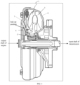
- FIG. 1 is a schematic structural diagram of a hydraulic torque converter in a hydraulic automatic gearbox.
- the hydraulic torque converter 1 is formed mainly by a pump impeller 2, a turbine 3, a guide pulley 4, a one-way clutch 5, a torque-converter housing 6, a lock-up clutch 7 and so on.
- the pump impeller 2 is mounted to the torque-converter housing 6, and the torque-converter housing 6 may be fastened by using bolts.
- the pump impeller 2 is connected to the output shaft of the engine, and is rotatable by its driving.
- the turbine 3 is the outputting component of the hydraulic torque converter, and is connected to the input shaft of the planetary-gear transmission via a spline.
- the guide pulley 4 is located between the pump impeller 2 and the turbine 3, and it can change the angle of the impact by the liquid on the turbine 3, thereby changing the outputted torque of the turbine 3.
- the guide pulley 4 is provided with the one-way clutch 5, and the one-way clutch 5 causes that the guide pulley 4 can merely rotate in the same direction as the pump impeller 2, and cannot rotate in the reverse direction.
- the lock-up clutch 7, in the engagement state can realize the mechanical connection between the pump impeller 2 and the turbine 3, whereby the hydraulic transmission between the pump impeller 2 and the turbine 3 is converted into mechanical transmission to increase the transmission efficiency.
- the guide pulley 4 by the effect of the one-way clutch, hinders the gearbox oil, to cause it to counter-act on the turbine 3, whereby the impact force of the gearbox oil exerted on the turbine 3 is doubled. Therefore, the vehicle equipped with the hydraulic automatic gearbox, in the low-speed state, can decelerate while increasing the torque, thereby having a good off-road performance.
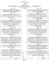
- FIG. 2 is a flow chart of the implementation of the method.
- the controlling method according to the present application can be applied to a hybrid-power vehicle employing the P2 architecture and equipped with a hydraulic automatic transmission.
- the power system of the vehicle has a P2 electric motor 3 and a gearbox that includes a hydraulic torque converter 1, and the power system of the vehicle further has an engine 9, a K0 clutch 10, a main gearbox body 8 and a gearbox output shaft 12.
- the hydraulic torque converter 1 has a pump impeller 2, a turbine 3, a guide pulley 4 and a lock-up clutch 7.
- the engine 9 and a P2 electric motor 11 may be engaged or disengaged. If the K0 clutch 10 is disengaged, then the engine 9 and the P2 electric motor 11 are disengaged, and the P2 electric motor 11 solely drives the vehicle wheels, in which case the vehicle operates in a purely electric mode. If the K0 clutch 10 is engaged, then the engine 9 and the P2 electric motor 11 are engaged, and the engine 9 and the P2 electric motor 11 drive the vehicle wheels together, in which case the vehicle operates in a hybrid-power mode.
- the method for controlling starting of a vehicle includes totally four steps from the step 201 to the step 204. The four steps will be described in detail below.
- Step 201 acquiring the starting type of the vehicle.
- the vehicle Before the starting type of the vehicle is acquired, it may be firstly determined whether the vehicle is in a to-start state. For example, it may be determined whether the vehicle is in the to-start state according to a key signal, a gear signal, a brake-pedal signal, and so on, of the vehicle. Generally, when the key has been turned to the ON gear, after the entire-vehicle controller has controlled the high-voltage and low-voltage systems of the vehicle to be powered on, when the brake-pedal signal is not-braking and the gear signal is the D/R gear, it may be determined that the vehicle is in the to-start state. When the brake-pedal signal is being-braking or the gear signal is the PIN gear, it may be determined that the vehicle is not in the to-start state, and the gearbox is required to disengage the clutch to cut off the power.
- the starting type of the vehicle may be acquired by acquiring the state of the accelerator pedal. For example, if the accelerator pedal is in an unpressed state, then it may be determined that the starting type of the vehicle is worming starting. If the accelerator pedal is in a pressed state, then it may be determined that the starting type of the vehicle is accelerated starting. Regarding the different starting types, it is required to employ different controlling logics to realize the vehicle starting. Therefore, in the step 201, firstly the starting type of the vehicle may be acquired, and subsequently the subsequent starting controlling may be performed according to the different starting types.
- Step 202 determining a basic power output value and a hydraulic-conversion hysteresis compensation value for compensating for the hysteresis amount of the hydraulic torque converter that correspond to the starting type acquired in the step 201.
- the basic power output values and the hydraulic-conversion hysteresis compensation values corresponding to the different starting types are usually different.
- the hysteresis caused by the hydraulic torque converter may be compensated for with respect to the different starting types.
- the basic target pump-impeller rotational speed may be corrected by using the hydraulic-conversion load, to realize the prediction on the target rotational speed of the pump impeller.
- the controlling process requires the communication and the interaction between the entire-vehicle controller and the gearbox controller.
- the entire-vehicle controller may compensate for the originally calculated basic accelerator-pedal torque according to the accelerator-pedal opening degree (the accelerator-pedal torque refers to the torque request that is obtained by table looking-up or calculation according to the accelerator-pedal opening degree), to realize the prediction on the target accelerator-pedal torque.
- the accelerator-pedal torque refers to the torque request that is obtained by table looking-up or calculation according to the accelerator-pedal opening degree
- Step 203 compensating for the basic power output value according to the hydraulic-conversion hysteresis compensation value, to obtain a target power output value; and according to the target power output value, determining the to-be-outputted torques of the P2 electric motor and the engine, or the to-be-outputted torque of the P2 electric motor, with respect to the starting type acquired in the step 201.
- Step 204 controlling the vehicle to start according to the to-be-outputted torques of the P2 electric motor and the engine or the to-be-outputted torque of the P2 electric motor determined in the step 203.
- the to-be-outputted torque of the P2 electric motor with respect to the starting type may be determined according to the target power output value obtained after the compensation.
- the to-be-outputted torques of the P2 electric motor and the engine with respect to the starting type may be determined according to the target power output value obtained after the compensation.
- the method for controlling starting of a vehicle shown in FIG. 1 is suitable for a vehicle that employs the power architecture that includes a P2 electric motor and a gearbox that includes a hydraulic torque converter.
- the controlling method includes firstly acquiring the starting type of the vehicle, and determining the basic power output value and the hydraulic-conversion hysteresis compensation value for compensating for the hysteresis amount of the hydraulic torque converter that correspond to that starting type; subsequently, compensating for the basic power output value according to the hydraulic-conversion hysteresis compensation value, and according to the target power output value obtained after the compensation, determining the to-be-outputted torques of the P2 electric motor and the engine, or the to-be-outputted torque of the P2 electric motor, with respect to the starting type; and, finally, controlling the vehicle to start according to the to-be-outputted torques of the P2 electric motor and the engine or the to-be-outputted torque of the P2 electric motor.
- the controlling method compensates for the basic power output value by using the hydraulic-conversion hysteresis compensation value, and can predict the required target power output value based on the variation of the torque transmission characteristic of the hydraulic torque converter at the starting stage, and the to-be-outputted torque that is determined and obtained according to the predicted target power output value that is obtained after the compensation can increase the power response speed of the vehicle.
- the power architecture that includes the P2 electric motor and the gearbox that includes the hydraulic torque converter can utilize the characteristics of the P2 electric motor of a quick torque response and a high precision, thereby increasing the power response speed of the vehicle, to realize quick starting.
- the starting type of the vehicle acquired in the step 201 may include the worming starting.
- the corresponding basic power output value with respect to the worming starting may include a purely-electric-worming-pump-impeller basic target rotational speed and a traditional-worming-pump-impeller basic target rotational speed.
- the corresponding hydraulic-conversion hysteresis compensation value with respect to the worming starting may include a first rotational-speed compensation value.
- FIG. 4 shows a flow chart of the implementation of the method for controlling starting of a vehicle with respect to the worming starting according to the present embodiment.
- the controlling method may include totally fifteen steps of the step 301 to the step 315. Those steps will be described in detail below.
- Step 301 acquiring the operation mode of the vehicle.
- the operation mode of the vehicle may be acquired by determining whether the engine has been started up.
- the operation mode of the vehicle may also be acquired by acquiring the state of the K0 clutch and determining the state of the K0 clutch.
- the engine is in the off-state, or the K0 clutch is in the disengagement state, then it may be determined that the vehicle is operating in the purely electric mode. If the engine is in the on-state, and the K0 clutch is in the engagement state, then it may be determined that the vehicle is operating in the hybrid-power mode.
- step 301 After the operation mode of the vehicle has been acquired in the step 301, if the vehicle is operating in the purely electric mode, then the steps 302, 304, 306, 308, 310, 312 and 314 are executed.
- Step 302 acquiring the purely-electric-worming-pump-impeller basic target rotational speed.
- the purely-electric-worming-pump-impeller basic target rotational speed may be 800rpm.
- Step 304 acquiring the hydraulic-conversion load of the hydraulic torque converter and the slope resistance of the vehicle.
- the speed ratio refers to the ratio of the turbine rotational speed to the basic target pump-impeller rotational speed.
- the basic target pump-impeller rotational speed is the purely-electric-worming-pump-impeller basic target rotational speed.
- the basic target pump-impeller rotational speed is the traditional-worming-pump-impeller basic target rotational speed.
- the sequence of the step 302 and the step 304 is not limited, and they may be simultaneously executed, and may also be sequentially executed.
- the purely-electric-worming-pump-impeller basic target rotational speed acquired in the step 302 may be corrected according to the hydraulic-conversion load and the slope resistance acquired in the step 304, so as to increase the purely-electric-worming-pump-impeller basic target rotational speed, thereby increasing the power response speed of the vehicle, to realize quick starting.
- Step 306 according to the hydraulic-conversion load and a first predetermined rotational-speed-compensation table, determining the first rotational-speed compensation value corresponding to the worming starting.
- Step 308 according to the slope resistance and a second predetermined rotational-speed-compensation table, determining a second rotational-speed compensation value corresponding to the worming starting.
- Step 310 compensating for the purely-electric-worming-pump-impeller basic target rotational speed according to the first rotational-speed compensation value and the second rotational-speed compensation value.
- the sequence of the step 306 and the step 308 is not limited.
- the first predetermined rotational-speed-compensation table and the second predetermined rotational-speed-compensation table may be obtained by pre-calibration.
- the first predetermined rotational-speed-compensation table is a table of the correspondence relation between the hydraulic-conversion loads and the first rotational-speed compensation values
- the second predetermined rotational-speed-compensation table is a table of the correspondence relation between the slope resistances and the second rotational-speed compensation values.
- the first predetermined rotational-speed-compensation table may be as shown by Table 1
- the second predetermined rotational-speed-compensation table may be as shown by Table 2.
- Table 1 Hydraulic-conversion load/N ⁇ m 5 10 15 20 26 65 85 95 110 125 First rotational-speed compensation value/rpm 0 30 50 75 75 75 75 75 75 75 75 Table 2 Slope resistance/% 0 5 10 13 16 18 20 25 28 Second rotational-speed compensation value/rpm 0 20 50 70 90 100 120 120 150
- Table 1 and Table 2 are merely examples of the first predetermined rotational-speed-compensation table and the second predetermined rotational-speed-compensation table, and do not limit the first predetermined rotational-speed-compensation table and the second predetermined rotational-speed-compensation table.
- the first predetermined rotational-speed-compensation table and the second predetermined rotational-speed-compensation table may be obtained by calibration according to practical demands.
- the obtained hydraulic-conversion load is 10N ⁇ m and the slope is 5%
- the first rotational-speed compensation value is 30rpm
- the second rotational-speed compensation value is 20rpm.
- the purely-electric-worming-pump-impeller basic target rotational speed is 800rpm
- the purely-electric-worming-pump-impeller target rotational speed that has been compensated for is 850rpm.
- the purely-electric-worming-pump-impeller basic target rotational speed is compensated for according to the first rotational-speed compensation value and the second rotational-speed compensation value.
- the sum of the first rotational-speed compensation value, the second rotational-speed compensation value and the purely-electric-worming-pump-impeller basic target rotational speed is calculated, to obtain the purely-electric-worming-pump-impeller target rotational speed that has been compensated for (i.e., the target power output value obtained after the compensation).
- Step 312 acquiring the actual rotational speed of the P2 electric motor.
- Step 314 according to the purely-electric-worming-pump-impeller target rotational speed and the actual rotational speed, determining the to-be-outputted torque of the P2 electric motor corresponding to the purely electric mode with respect to the worming starting.
- Proportion-Integral-Differential (PID) controlling may be performed according to the purely-electric-worming-pump-impeller target rotational speed and the actual rotational speed of the P2 electric motor, and the torque obtained by calculation by using the PID algorithm may be, as the torque request of the P2 electric motor (i.e., the to-be-outputted torque of the P2 electric motor), sent to an electric-motor controller (Motor Control Unit, MCU).
- PID Proportion-Integral-Differential
- the to-be-outputted torque of the P2 electric motor that is obtained by the PID controlling may be 171.6N ⁇ m.
- the purely-electric-worming-pump-impeller basic target rotational speed can be corrected based on the hydraulic-conversion load.
- the purely-electric-worming-pump-impeller basic target rotational speed can be corrected based on the environmental resistance, for example, the slope resistance.
- the purely-electric-worming-pump-impeller target rotational speed obtained by the correction can increase the purely-electric-worming-pump-impeller basic target rotational speed, thereby increasing the power response speed of the vehicle, to realize quick starting.
- step 301 After the operation mode of the vehicle has been acquired in the step 301, if the vehicle is operating in the hybrid-power mode, then the steps 303, 305, 307, 309, 311, 313 and 315 are executed.
- Step 303 acquiring the traditional-worming-pump-impeller basic target rotational speed.
- the traditional-worming-pump-impeller basic target rotational speed may be 800rpm.
- Step 305 acquiring the hydraulic-conversion load of the hydraulic torque converter, the slope resistance of the vehicle and the electricity-generation load of the P2 electric motor.
- the sequence of the step 303 and the step 305 is not limited.
- the processes of acquiring the hydraulic-conversion load of the hydraulic torque converter and the slope resistance of the vehicle are similar to those of the step 304, and are not discussed further herein.
- the electricity-generation load of the P2 electric motor is also acquired.
- the electricity-generation load of the P2 electric motor may be reduced, so as to reduce the torque that the engine is required to output, thereby increasing the power response speed of the vehicle.
- Step 307 according to the hydraulic-conversion load and a first predetermined rotational-speed-compensation table, determining the first rotational-speed compensation value corresponding to the worming starting.
- Step 309 according to the slope resistance and a second predetermined rotational-speed-compensation table, determining a second rotational-speed compensation value corresponding to the worming starting.
- Step 311 compensating for the traditional-worming-pump-impeller basic target rotational speed according to the first rotational-speed compensation value and the second rotational-speed compensation value.
- the sequence of the step 307 and the step 309 is not limited.
- the processes of determining the first rotational-speed compensation value and the second rotational-speed compensation value may refer to the step 306 and the step 308.
- the table looking-up in the first predetermined rotational-speed-compensation table according to the hydraulic-conversion load and the table looking-up in the second predetermined rotational-speed-compensation table according to the slope resistance may refer to the detailed description on the step 310. Those contents are not discussed further herein.
- the traditional-worming-pump-impeller basic target rotational speed is compensated for according to the first rotational-speed compensation value and the second rotational-speed compensation value.
- the sum of the first rotational-speed compensation value, the second rotational-speed compensation value and the traditional-worming-pump-impeller basic target rotational speed is calculated, to obtain the traditional-worming-pump-impeller target rotational speed that has been compensated for (i.e., the target power output value obtained after the compensation).
- Step 313 according to the traditional-worming-pump-impeller target rotational speed, determining an idle-speed target rotational speed of the vehicle.
- Step 315 correcting the electricity-generation load of the P2 electric motor, and performing idle-speed controlling according to the corrected electricity-generation load and the idle-speed target rotational speed, to determine the to-be-outputted torques of the P2 electric motor and the engine corresponding to the hybrid-power mode with respect to the worming starting.
- the traditional-worming-pump-impeller target rotational speed may be directly determined to be the idle-speed target rotational speed of the vehicle. For example, if the traditional-worming-pump-impeller target rotational speed obtained in the step 311 is 1050rpm, then, in the step 313, it can be determined that the idle-speed target rotational speed of the vehicle is 1050rpm.
- the corrected electricity-generation load is less than the currently acquired electricity-generation load, to reduce the electricity-generation load of the P2 electric motor, which may particularly be embodied by correcting the electricity-generation load of the P2 electric motor.
- the current electricity-generation torque of the P2 electric motor may be acquired. If the current electricity-generation torque of the P2 electric motor is large, that indicates that, in order to maintain the state of charge of the power battery or enable the power battery to operate in the safe state, the P2 electric motor requires a large electricity-generation torque (i.e., the electricity-generation load of the P2 electric motor is large, and the electricity-generation torque is provided by the engine).
- the torque that is required to be outputted by the engine and generates electricity for the P2 electric motor may be reduced by reducing the electricity-generation load to a small extent. If the current electricity-generation torque of the P2 electric motor is small, that indicates that the state of charge or the operation state of the power battery is relatively safe, and the electricity-generation load of the P2 electric motor is small. In this case, the torque that is required to be outputted by the engine and generates electricity for the P2 electric motor may be reduced by reducing the electricity-generation load to a large extent.
- the electricity-generation torque that has been corrected may be 0, so as to, when the electricity-generation load of the P2 electric motor is small, reduce a major part of the electricity-generation load to reduce the torque that is required to be outputted by the engine and generates electricity for the P2 electric motor.
- the electricity-generation torque that has been corrected may be - 80N ⁇ m, so as to maintain the state of charge of the power battery or enable the power battery to operate in the safe state.
- the process may include, according to the corrected electricity-generation load and the idle-speed target rotational speed, performing idle-speed controlling over the traditional worming in the hybrid-power mode, and, based on the idle-speed controlling process, determining the to-be-outputted torque of the engine and the to-be-outputted torque of the P2 electric motor; and subsequently, sending the to-be-outputted torque of the P2 electric motor to the MCU, and sending the to-be-outputted torque of the engine to an engine controller (Engine Control Module, ECM).
- ECM Engine Control Module
- the traditional-worming-pump-impeller basic target rotational speed may be compensated for based on the hydraulic-conversion load and the environmental resistance.
- the influence by the electricity-generation load of the P2 electric motor on the torque outputted by the engine is also taken into consideration, and the electricity-generation load of the P2 electric motor is reduced to the largest extent.
- the traditional-worming-pump-impeller target rotational speed obtained after the compensation can increase the traditional-worming-pump-impeller basic target rotational speed.
- the reduction of the electricity-generation load of the P2 electric motor can reduce the torque that is required to be outputted by the engine and generates electricity for the P2 electric motor, so as to enable the engine to allocate more torque for driving the vehicle to start.
- the controlling method including the steps 303-315 cannot only increase the traditional-worming-pump-impeller basic target rotational speed, but also can reduce the torque that is outputted by the engine and generates electricity for the P2 electric motor, thereby increasing the power response speed of the vehicle, to realize quick starting.
- the starting type of the vehicle acquired in the step 201 may include the accelerated starting.
- the corresponding basic power output value with respect to the accelerated starting may include the basic accelerator-pedal torque.
- the corresponding hydraulic-conversion hysteresis compensation value with respect to the accelerated starting may include an accelerator-pedal shaft-end-torque compensation value.
- FIG. 5 shows a flow chart of the implementation of the method for controlling starting of a vehicle with respect to the accelerated starting according to the present embodiment.
- the controlling method may include totally nine steps of the step 401 to the step 409. Those steps will be described in detail below.
- Step 401 acquiring the accelerator-pedal opening degree.
- Step 402 according to the accelerator-pedal opening degree and a predetermined basic-torque table, determining the basic accelerator-pedal torque corresponding to the accelerated starting.
- the basic accelerator-pedal torque that is obtained by table looking-up according to the accelerator-pedal opening degree is the accelerator-pedal torque when the vehicle is in the stable-operation state.
- the starting controlling is performed based on merely the basic accelerator-pedal torque, then the outputted torque might be not capable of realizing the expected acceleration target, which causes the problems of a slow starting and a slow power response.
- the predetermined basic-torque table in the step 402 may be a table of the correspondence relation between the accelerator-pedal opening degrees and the basic accelerator-pedal torques.
- the basic accelerator-pedal torque may also be determined by referring to the current vehicle speed. For example, if the current vehicle speed is 10km/h, and the accelerator-pedal opening degree is 10%, by looking up the predetermined basic-torque table, it can be determined that the corresponding basic accelerator-pedal torque is 515N ⁇ m. If the current vehicle speed is 10km/h, and the accelerator-pedal opening degree is 5%, by looking up the predetermined basic-torque table, it can be determined that the corresponding basic accelerator-pedal torque is 227N ⁇ m.
- Step 403 when the state of a lock-up clutch in the hydraulic torque converter is being-disengaged, determining the accelerator-pedal shaft-end-torque compensation value corresponding to the accelerated starting according to the accelerator-pedal opening degree.
- the speed ratio of the power train system increases, and the changing of the speed ratio influences the torques of the wheel end and the shaft end of the entire vehicle.
- the real-time speed ratio of the power train system has already changed, which causes that the torque request calculated by the entire-vehicle controller cannot realize the expected acceleration target. Therefore, in the step 403, the accelerator-pedal shaft-end-torque compensation value corresponding to the accelerated starting is determined according to the accelerator-pedal opening degree, whereby the required target accelerator-pedal torque can be predicted according to the accelerator-pedal shaft-end-torque compensation value.
- the state of the lock-up clutch may be detected. If the lock-up clutch is in the disengagement state, then the action of the step 403 is executed, i.e., determining the accelerator-pedal shaft-end-torque compensation value corresponding to the accelerated starting according to the accelerator-pedal opening degree. If the lock-up clutch is in the engagement state and the vehicle speed exceeds a certain value, then the calculation of the accelerator-pedal shaft-end-torque compensation value is stopped, and the torque compensation is exited.
- the accelerator-pedal shaft-end-torque compensation value corresponding to the current accelerator-pedal opening degree may be determined by looking up a predetermined torque-compensation table according to the accelerator-pedal opening degree.
- the predetermined torque-compensation table may be a table of the correspondence relation between the accelerator-pedal opening degrees and the accelerator-pedal shaft-end-torque compensation values.
- the accelerator-pedal shaft-end-torque compensation value may also be determined by referring to the accelerator-pedal opening degree and a change rate of the accelerator-pedal opening degree at the same time. For example, if the accelerator-pedal opening degree is 10%, and the change rate of the accelerator-pedal opening degree is 50%, then the accelerator-pedal shaft-end-torque compensation value may be 100N ⁇ m.
- Step 404 compensating for the basic accelerator-pedal torque according to the accelerator-pedal shaft-end-torque compensation value, to, after the compensation, obtain the target accelerator-pedal torque.
- the lock-up clutch is in the disengagement state, then the sum of the accelerator-pedal shaft-end-torque compensation value and the basic accelerator-pedal torque is calculated, thereby obtaining the target accelerator-pedal torque. If the lock-up clutch is in the engagement state, then the basic accelerator-pedal torque may be directly used as the target accelerator-pedal torque.
- the basic accelerator-pedal torque obtained in the step 402 is 515N ⁇ m
- the accelerator-pedal shaft-end-torque compensation value obtained in the step 403 is 100N ⁇ m
- the step 404 the sum of the accelerator-pedal shaft-end-torque compensation value and the basic accelerator-pedal torque is calculated, and the obtained target accelerator-pedal torque is 615N ⁇ m.
- Step 405 acquiring the operation mode of the vehicle.
- Step 406 if the operation mode is the purely electric mode, determining the target accelerator-pedal torque to be the to-be-outputted torque of the P2 electric motor with respect to the accelerated starting.
- 615N ⁇ m may be determined to be the to-be-outputted torque of the P2 electric motor with respect to the accelerated starting.
- the particular process of acquiring the operation mode of the vehicle may refer to the step 301, and is not discussed further herein. If the operation mode is the purely electric mode, Then the process includes, at the stage when the lock-up clutch is not engaged, compensating for the basic accelerator-pedal torque according to the accelerator-pedal shaft-end-torque compensation value, sending the target accelerator-pedal torque obtained after the compensation as the torque request of the P2 electric motor (the to-be-outputted torque of the P2 electric motor with respect to the accelerated starting) to the MCU, till the lock-up clutch is engaged, and exiting the torque compensation.
- the process includes, at the stage when the lock-up clutch is not engaged, compensating for the basic accelerator-pedal torque according to the accelerator-pedal shaft-end-torque compensation value, sending the target accelerator-pedal torque obtained after the compensation as the torque request of the P2 electric motor (the to-be-outputted torque of the P2 electric motor with respect to the accelerated starting) to the MCU, till the lock-up
- Step 407 if the operation mode is the hybrid-power mode, acquiring an electricity-generation load of the P2 electric motor.
- Step 408 correcting the electricity-generation load, and according to the corrected electricity-generation load, determining the to-be-outputted torque of the P2 electric motor with respect to the accelerated starting.
- Step 409 according to the sum of the to-be-outputted torque of the P2 electric motor and the target accelerator-pedal torque, determining the to-be-outputted torque of the engine with respect to the accelerated starting.
- the corrected electricity-generation load is less than the currently acquired electricity-generation load. If the operation mode is the hybrid-power mode, then, on the basis of the compensation for the basic accelerator-pedal torque according to the accelerator-pedal shaft-end-torque compensation value, and by taking into consideration the limited capacity of the engine in the low-rotational-speed state, part of the electricity-generation load of the P2 electric motor may be exited at the stage of the accelerated starting, so as to ensure the power performance of the entire vehicle.
- the steps 407-409 may be particularly executed through the following steps:
- the predetermined starting-torque correction table may be a table of the correspondence relation among the electricity-generation torques, the vehicle speeds and the corrected starting torques. For example, if the current vehicle speed is 4km/h, and the current electricity-generation torque is -30N ⁇ m, the corrected starting torque that is determined by table looking-up is -30N ⁇ m; in other words, the corrected electricity-generation load is 0. In other words, when the current electricity-generation torque is small, the electricity-generation load of the P2 electric motor may be completely exited, so as to ensure the power performance of the entire vehicle.
- the corrected starting torque that is determined by table looking-up is -20N ⁇ m; in other words, the corrected electricity-generation load is -80N ⁇ m.
- the electricity-generation load of the P2 electric motor may be partially exited, so as to ensure the power performance of the entire vehicle, and part of the electricity-generation load of the P2 electric motor is maintained, so as to maintain the state of charge of the power battery or enable the power battery to operate in the safe state.
- the target accelerator-pedal torque obtained in the step 404 is 615N ⁇ m
- the corrected electricity-generation load is 0
- the to-be-outputted torque of the P2 electric motor with respect to the accelerated starting is 0, and the to-be-outputted torque of the engine with respect to the accelerated starting is 615N ⁇ m.
- the corrected electricity-generation load is -80N ⁇ m
- the to-be-outputted torque of the P2 electric motor with respect to the accelerated starting is 80N ⁇ m
- the to-be-outputted torque of the engine with respect to the accelerated starting is 695N m.
- the basic accelerator-pedal torque is compensated for according to the accelerator-pedal shaft-end-torque compensation value, and, simultaneously, the electricity-generation torque request of the P2 electric motor with respect to the starting stage is corrected by using the current electricity-generation torque of the P2 electric motor. If the current electricity-generation torque of the P2 electric motor is larger, the electricity-generation torque of the P2 electric motor at the starting stage is larger; in other words, the corrected starting torque used for correcting the current electricity-generation torque of the P2 electric motor is smaller.
- the corrected starting torque may be obtained particularly by table looking-up according to the current electricity-generation torque of the P2 electric motor and the current vehicle speed.
- the corrected starting torque is larger.
- the difference between the current electricity-generation torque and the corrected starting torque is, as the to-be-outputted torque of the P2 electric motor, allocated to the P2 electric motor and sent to the MCU, and the sum of the to-be-outputted torque of the P2 electric motor and the target accelerator-pedal torque is, as the to-be-outputted torque of the engine, sent to the ECM, till the lock-up clutch is engaged and the torque compensation is exited.
- the method for controlling starting of a vehicle according to the present application may be applied to a vehicle that employs the power architecture that includes a P2 electric motor and a gearbox that includes a hydraulic torque converter.
- the controlling method can, by utilizing the characteristics of the hybrid-power P2 architecture, solve the problem of traditional oil-burning vehicles that, because of the hardware characteristics of the hydraulic automatic gearbox, quick starting cannot be realized.
- the controlling method includes firstly acquiring the starting type of the vehicle, and determining the basic power output value and the hydraulic-conversion hysteresis compensation value for compensating for the hysteresis amount of the hydraulic torque converter that correspond to that starting type; subsequently, compensating for the basic power output value according to the hydraulic-conversion hysteresis compensation value, and according to the target power output value obtained after the compensation, determining the to-be-outputted torques of the P2 electric motor and the engine, or the to-be-outputted torque of the P2 electric motor, with respect to the starting type; and, finally, controlling the vehicle to start according to the to-be-outputted torques or to-be-outputted torque.
- the controlling method can predict the variation of the torque transmission characteristic of the hydraulic torque converter at the starting stage, and compensate based on the torque transmission characteristic of the hydraulic torque converter, thereby, without changing the hardware characteristics of the hydraulic torque converter, by controlling the to-be-outputted torques of the engine and the P2 electric motor, improving the manipulating sense at the starting stage of vehicles equipped with the hydraulic torque converter, to realize quick starting.
- sequence of the serial numbers of the steps in the above embodiments do not indicate the sequence of the execution thereof, and the sequence of the execution of the steps should be decided according to their functions and internal logic.
- the sequence of the serial numbers of the steps should not limit the process of the implementation of the present application in any manner.
- FIG. 6 shows a schematic structural diagram of an apparatus for controlling starting of a vehicle according to an embodiment of the present application.
- the vehicle that applies the apparatus for controlling starting of a vehicle is provided with a P2 electric motor and a gearbox that includes a hydraulic torque converter.
- FIG. 6 merely shows the parts relevant to the present application.
- the apparatus for controlling starting of a vehicle includes an acquiring module 61, a first processing module 62, a second processing module 63 and a controlling module 64.
- the acquiring module 61 is configured for acquiring a starting type of the vehicle
- the apparatus for controlling starting of a vehicle can be suitable for a vehicle that employs the power architecture that includes a P2 electric motor and a gearbox that includes a hydraulic torque converter.
- the controlling apparatus includes firstly acquiring the starting type of the vehicle, and determining the basic power output value and the hydraulic-conversion hysteresis compensation value for compensating for the hysteresis amount of the hydraulic torque converter that correspond to that starting type; subsequently, compensating for the basic power output value according to the hydraulic-conversion hysteresis compensation value, and according to the target power output value obtained after the compensation, determining the to-be-outputted torques of the P2 electric motor and the engine, or the to-be-outputted torque of the P2 electric motor, with respect to the starting type; and, finally, controlling the vehicle to start according to the to-be-outputted torques or to-be-outputted torque.
- the controlling apparatus compensates for the basic power output value by using the hydraulic-conversion hysteresis compensation value, and can predict the required target power output value based on the variation of the torque transmission characteristic of the hydraulic torque converter at the starting stage, and the to-be-outputted torque that is determined and obtained according to the predicted target power output value that is obtained after the compensation can increase the power response speed of the vehicle.
- the power architecture that includes the P2 electric motor and the gearbox that includes the hydraulic torque converter can utilize the characteristics of the P2 electric motor of a quick torque response and a high precision, thereby increasing the power response speed of the vehicle, to realize quick starting.
- the starting type includes worming starting;
- the basic power output value includes a purely-electric-worming-pump-impeller basic target rotational speed and a traditional-worming-pump-impeller basic target rotational speed;
- the hydraulic-conversion hysteresis compensation value includes a first rotational-speed compensation value;
- the first processing module 62 may be configured for: acquiring an operation mode of the vehicle; if the operation mode is a purely electric mode, acquiring the purely-electric-worming-pump-impeller basic target rotational speed corresponding to the purely electric mode with respect to the worming starting; if the operation mode is a hybrid-power mode, acquiring the traditional-worming-pump-impeller basic target rotational speed corresponding to the hybrid-power mode with respect to the worming starting; acquiring a hydraulic-conversion load of the hydraulic torque converter; and according to the hydraulic-conversion load and a first predetermined rotational-speed-compensation table, determining the first rotational
- the first processing module 62 may further be configured for: acquiring a slope resistance of the vehicle; and according to the slope resistance and a second predetermined rotational-speed-compensation table, determining a second rotational-speed compensation value corresponding to the worming starting; and the second processing module 63 may be configured for: if the operation mode is the purely electric mode, compensating for the purely-electric-worming-pump-impeller basic target rotational speed according to the first rotational-speed compensation value and the second rotational-speed compensation value; and if the operation mode is the hybrid-power mode, compensating for the traditional-worming-pump-impeller basic target rotational speed according to the first rotational-speed compensation value and the second rotational-speed compensation value.
- the target power output value includes a purely-electric-worming-pump-impeller target rotational speed
- the second processing module 63 may be configured for: acquiring an actual rotational speed of the P2 electric motor; and according to the purely-electric-worming-pump-impeller target rotational speed and the actual rotational speed, determining the to-be-outputted torque of the P2 electric motor corresponding to the purely electric mode with respect to the worming starting.
- the target power output value includes a traditional-worming-pump-impeller target rotational speed
- the second processing module 63 may be configured for: acquiring an electricity-generation load of the P2 electric motor; correcting the electricity-generation load, to obtain a corrected electricity-generation load, wherein the corrected electricity-generation load is less than the electricity-generation load; according to the traditional-worming-pump-impeller target rotational speed, determining an idle-speed target rotational speed of the vehicle; and according to the idle-speed target rotational speed and the corrected electricity-generation load, performing idle-speed controlling, to determine the to-be-outputted torques of the P2 electric motor and the engine corresponding to the hybrid-power mode with respect to the worming starting.
- the starting type includes accelerated starting;
- the basic power output value includes a basic accelerator-pedal torque;
- the hydraulic-conversion hysteresis compensation value includes an accelerator-pedal shaft-end-torque compensation value;
- the first processing module 62 may be configured for: acquiring an accelerator-pedal opening degree; according to the accelerator-pedal opening degree and a predetermined basic-torque table, determining the basic accelerator-pedal torque corresponding to the accelerated starting; and when a state of a lock-up clutch in the hydraulic torque converter is being-disengaged, determining the accelerator-pedal shaft-end-torque compensation value corresponding to the accelerated starting according to the accelerator-pedal opening degree.
- the target power output value includes a target accelerator-pedal torque
- the second processing module 63 may be configured for: acquiring an operation mode of the vehicle; and if the operation mode is a purely electric mode, determining the target accelerator-pedal torque to be the to-be-outputted torque of the P2 electric motor with respect to the accelerated starting.
- the target power output value includes a target accelerator-pedal torque
- the second processing module 63 may be configured for: acquiring an operation mode of the vehicle; if the operation mode is a hybrid-power mode, acquiring an electricity-generation load of the P2 electric motor; correcting the electricity-generation load, to obtain a corrected electricity-generation load, wherein the corrected electricity-generation load is less than the electricity-generation load; according to the corrected electricity-generation load, determining the to-be-outputted torque of the P2 electric motor with respect to the accelerated starting; and determining a sum of the to-be-outputted torque of the P2 electric motor and the target accelerator-pedal torque to be the to-be-outputted torque of the engine with respect to the accelerated starting.
- FIG. 7 is a schematic diagram of a controller according to the present application.
- the controller 7 includes a processor 70, a memory 71, and a computer program 72 that is stored in the memory 71 and executable in the processor 70.
- the processor 70 when executing the computer program 72, implements the steps of the above embodiments of the method for controlling starting of a vehicle, for example, the step 201 to the step 204 shown in FIG. 2 , or the step 301 to the step 315 shown in FIG. 4 , or the step 401 to the step 409 shown in FIG. 5 .
- the processor 70 when executing the computer program 72, implements the functions of the modules according to the above device embodiments, for example, the functions of the modules 61 to 64 shown in FIG. 6 .
- the computer program 72 may be divided into one or more modules/units.
- the computer program 72 may be divided into the modules 61 to 64 shown in FIG. 6 .
- Those modules/units are stored in the memory 71, and executed by the processor 70, to complete the technical solutions according to the present application.
- Those modules/units may be a series of computer program instruction segments that can complete specific functions, and the instruction segments can describe the process of the execution of the computer program 72 in the controller 7.
- the controller 7 may be an entire-vehicle controller or another controlling device that controls the vehicle.
- the controller 7 may include, without limitation, a processor 70 and a memory 71.
- FIG. 7 is merely an example of the controller 7, and does not limit the controller 7, and the controller 7 may include more or fewer components than those shown in FIG. 7 , or a combination of some of the components, or different components.
- the controller 7 may further include an inputting-outputting device, a network accessing device, a bus and so on.
- the processor 70 may be a Central Processing Unit (CPU), and may also be another generic processor, Digital Signal Processor (DSP), Application Specific Integrated Circuit (ASIC), Field-Programmable Gate Array (FPGA) or another programmable logic device, discrete gate or transistor logic device, discrete hardware assembly and so on.
- the generic processor may be a microprocessor or any other conventional processor.
- the memory 71 may be an internal storage unit of the controller 7, for example, a hard disk or an internal memory of the controller 7.
- the memory 71 may also be an external storage device of the controller 7, for example, a plug-connected hard disk, a Smart Media Card (SMC), a Secure Digital (SD) card, a Flash Card, and so on, that the controller 7 is equipped with. Further, the memory 71 may also include not only the internal storage unit of the controller 7 but also the external storage device.
- the memory 71 can store the computer program, and other programs and data that are required by the controller.
- the memory 71 can also temporarily store the data that have already been outputted or will be outputted.
- the division of the above functional units and modules is merely taken as an example for the description.
- the above functions may be allocated to be completed by different functional units and modules according to demands, i.e., dividing the internal structure of the apparatus into different functional units or modules, to complete all or some of the functions described above.
- the functional units and modules according to the embodiments may be integrated into one processing unit, or the units may also separately physically exist, or two or more of the units may also be integrated into one unit.
- the above-described integrated unit may be embodied in the form of hardware, and may also be embodied in the form of a software function unit.
- the disclosed apparatus/controller and method may be implemented in other manners.
- the above-described device/controller embodiments are merely illustrative.
- the division between the modules/units is merely a division in the logic functions, and in the practical implementation there may be another mode of division.
- multiple units or components may be combined or may be integrated into another system, or some of the features may be omitted, or not implemented.
- the coupling or direct coupling or communicative connection between the illustrated or discussed components may be via interfaces or the indirect coupling or communicative connection between the devices or units, and may be electric, mechanical or in other forms.
- the units that are described as separate components may or may not be physically separate, and the components that are displayed as units may or may not be physical units.
- the components and the units may be located at the same one location, and may also be distributed to a plurality of network units. Some or all of the units may be selected according to practical demands to realize the purposes of the technical solutions according to the embodiments.
- the integrated modules/units if embodied in the form of software function units and sold or used as an independent product, may be stored in a computer-readable storage medium.
- all or some of the processes of the methods according to the embodiments of the present application may be implemented by relative hardware under control by a computer program.
- the computer program may be stored in a computer-readable storage medium, and the computer program, when executed by a processor, can implement the steps of the above embodiments of the method for controlling starting of a vehicle.
- the computer program includes a computer program code, and the computer program code may be a source code, an object code, an executable file, some intermediate forms, and so on.
- the computer-readable medium may include any entity or device that can carry the computer program code, including a recording medium, a USB flash disk, a mobile hard disk drive, a diskette, an optical disk, a computer memory, a Read-Only Memory (ROM), a Random Access Memory (RAM), an electric carrier signal, a telecommunication signal, a software distribution medium and so on.
- a recording medium including a USB flash disk, a mobile hard disk drive, a diskette, an optical disk, a computer memory, a Read-Only Memory (ROM), a Random Access Memory (RAM), an electric carrier signal, a telecommunication signal, a software distribution medium and so on.
- ROM Read-Only Memory
- RAM Random Access Memory
Landscapes
- Engineering & Computer Science (AREA)
- Mechanical Engineering (AREA)
- Chemical & Material Sciences (AREA)
- Combustion & Propulsion (AREA)
- Transportation (AREA)
- General Engineering & Computer Science (AREA)
- Automation & Control Theory (AREA)
- Electric Propulsion And Braking For Vehicles (AREA)
Abstract
Description
- The present application claims the priority of the Chinese patent application filed on
January 20th, 2022 with the application number of CN 202210068435.4 - The present application relates to the technical field of vehicle-starting controlling, and particularly to a method and apparatus for controlling starting of a vehicle and a vehicle.
- Hydraulic automatic gearboxes (Automatic Transmission, AT), as an automatic gearbox that has a reliable structure and a good smoothness, because the lock-up clutch in their hydraulic torque converter is in the disengagement state at a low speed, can realize deceleration and torque increasing in the low-speed state, to improve the off-road performance of vehicles.
- However, also because the lock-up clutch is in the disengagement state, the torque outputted by the engine requires being transmitted from the pump impeller in the hydraulic torque converter by a hydraulic force to the turbine therein, and a certain flow rate is required to be established to drive the turbine to rotate. Therefore, the torque outputted by the engine has hysteresis, and cannot be timely transmitted out via the hydraulic torque converter. As a result, after a vehicle has been equipped with a gearbox formed by a hydraulic torque converter, the vehicle has the problems of a slow low-speed starting and a slow power response.
- The present application provides a method and apparatus for controlling starting of a vehicle and a vehicle, to solve the problem that, after a vehicle has been equipped with a gearbox formed by a hydraulic torque converter, the vehicle has a slow low-speed starting and a slow power response.
- In the first aspect, the present application provides a method for controlling starting of a vehicle, the vehicle is provided with a P2 electric motor and a gearbox that includes a hydraulic torque converter, and the method for controlling starting of the vehicle includes:
- acquiring a starting type of the vehicle;
- determining a basic power output value and a hydraulic-conversion hysteresis compensation value for compensating for a hysteresis amount of the hydraulic torque converter that correspond to the starting type;
- compensating for the basic power output value according to the hydraulic-conversion hysteresis compensation value, to obtain a target power output value;
- according to the target power output value, determining to-be-outputted torques of the P2 electric motor and an engine, or a to-be-outputted torque of the P2 electric motor, with respect to the starting type; and
- controlling the vehicle to start according to the to-be-outputted torques of the P2 electric motor and an engine or to-be-outputted torque of the P2 electric motor.
- In an alternative implementation, the starting type includes worming starting;
- the basic power output value includes a purely-electric-worming-pump-impeller basic target rotational speed and a traditional-worming-pump-impeller basic target rotational speed;
- the hydraulic-conversion hysteresis compensation value includes a first rotational-speed compensation value; and
- the step of determining the basic power output value and the hydraulic-conversion hysteresis compensation value for compensating for the hysteresis amount of the hydraulic torque converter that correspond to the starting type includes:
- when the starting type is the worming starting, acquiring an operation mode of the vehicle;
- if the operation mode is a purely electric mode, acquiring the purely-electric-worming-pump-impeller basic target rotational speed corresponding to the purely electric mode with respect to the worming starting;
- if the operation mode is a hybrid-power mode, acquiring the traditional-worming-pump-impeller basic target rotational speed corresponding to the hybrid-power mode with respect to the worming starting;
- acquiring a hydraulic-conversion load of the hydraulic torque converter; and
- according to the hydraulic-conversion load and a first predetermined rotational-speed-compensation table, determining the first rotational-speed compensation value corresponding to the worming starting.
- In an alternative implementation, after the step of acquiring the operation mode of the vehicle, the method for controlling starting of the vehicle further includes:
- acquiring a slope resistance of the vehicle; and
- according to the slope resistance and a second predetermined rotational-speed-compensation table, determining a second rotational-speed compensation value corresponding to the worming starting; and
- the step of compensating for the basic power output value according to the hydraulic-conversion hysteresis compensation value includes:
- if the operation mode is the purely electric mode, compensating for the purely-electric-worming-pump-impeller basic target rotational speed according to the first rotational-speed compensation value and the second rotational-speed compensation value; and
- if the operation mode is the hybrid-power mode, compensating for the traditional-worming-pump-impeller basic target rotational speed according to the first rotational-speed compensation value and the second rotational-speed compensation value.
- In an alternative implementation, the target power output value includes a purely-electric-worming-pump-impeller target rotational speed; and
- the step of, according to the target power output value, determining the to-be-outputted torque of the P2 electric motor with respect to the starting type includes:
- if the operation mode is the purely electric mode, acquiring an actual rotational speed of the P2 electric motor; and
- according to the purely-electric-worming-pump-impeller target rotational speed and the actual rotational speed, determining the to-be-outputted torque of the P2 electric motor corresponding to the purely electric mode with respect to the worming starting.
- In an alternative implementation, the target power output value includes a traditional-worming-pump-impeller target rotational speed; and
- the step of, according to the target power output value, determining the to-be-outputted torques of the P2 electric motor and the engine with respect to the starting type includes:
- if the operation mode is the hybrid-power mode, acquiring an electricity-generation load of the P2 electric motor;
- correcting the electricity-generation load, to obtain a corrected electricity-generation load, wherein the corrected electricity-generation load is less than the electricity-generation load;
- determining an idle-speed target rotational speed of the vehicle according to the traditional-worming-pump-impeller target rotational speed; and
- performing idle-speed controlling according to the idle-speed target rotational speed and the corrected electricity-generation load, to determine the to-be-outputted torques of the P2 electric motor and the engine corresponding to the hybrid-power mode with respect to the worming starting.
- In an alternative implementation, the starting type includes accelerated starting;
- the basic power output value includes a basic accelerator-pedal torque;
- the hydraulic-conversion hysteresis compensation value includes an accelerator-pedal shaft-end-torque compensation value; and
- the step of determining the basic power output value and the hydraulic-conversion hysteresis compensation value for compensating for the hysteresis amount of the hydraulic torque converter that correspond to the starting type includes:
- when the starting type is the accelerated starting, acquiring an accelerator-pedal opening degree;
- according to the accelerator-pedal opening degree and a predetermined basic-torque table, determining the basic accelerator-pedal torque corresponding to the accelerated starting; and
- when a state of a lock-up clutch in the hydraulic torque converter is being-disengaged, determining the accelerator-pedal shaft-end-torque compensation value corresponding to the accelerated starting according to the accelerator-pedal opening degree.
- In an alternative implementation, the target power output value includes a target accelerator-pedal torque; and
- the step of, according to the target power output value, determining the to-be-outputted torque of the P2 electric motor with respect to the starting type includes:
- acquiring an operation mode of the vehicle; and
- if the operation mode is a purely electric mode, determining the target accelerator-pedal torque to be the to-be-outputted torque of the P2 electric motor with respect to the accelerated starting.
- In an alternative implementation, the target power output value includes a target accelerator-pedal torque; and
- the step of, according to the target power output value, determining the to-be-outputted torques of the P2 electric motor and the engine with respect to the starting type includes:
- acquiring an operation mode of the vehicle;
- if the operation mode is a hybrid-power mode, acquiring an electricity-generation load of the P2 electric motor;
- correcting the electricity-generation load, to obtain a corrected electricity-generation load, wherein the corrected electricity-generation load is less than the electricity-generation load;
- determining the to-be-outputted torque of the P2 electric motor with respect to the accelerated starting according to the corrected electricity-generation load; and
- determining a sum of the to-be-outputted torque of the P2 electric motor and the target accelerator-pedal torque to be the to-be-outputted torque of the engine with respect to the accelerated starting.
- In an alternative implementation, the step of acquiring the starting type of the vehicle includes:
- when an accelerator pedal of the vehicle is not pressed down, determining the starting type to be worming starting; and
- when the accelerator pedal of the vehicle is pressed down, determining the starting type to be accelerated starting.
- In an alternative implementation, the step of acquiring the operation mode of the vehicle includes:
- when the engine of the vehicle is in an off-state, or a K0 clutch of the vehicle is in a disengagement state, determining the operation mode to be the purely electric mode; and
- when the engine of the vehicle is in an on-state, and the K0 clutch of the vehicle is in an engagement state, determining the operation mode to be the hybrid-power mode.
- In an alternative implementation, the hydraulic-conversion load is equal to C1*C2*n2, wherein C1 represents an oil-temperature correction factor of the hydraulic torque converter, C2 represents a correction factor for a ratio of a turbine rotational speed to a basic target pump-impeller rotational speed of the hydraulic torque converter, and n represents the basic target pump-impeller rotational speed of the hydraulic torque converter.
- In an alternative implementation, both of the purely-electric-worming-pump-impeller basic target rotational speed and the traditional-worming-pump-impeller basic target rotational speed are 800 revolutions per minute.
- In an alternative implementation, the method further includes: if the operation mode is the hybrid-power mode, acquiring a current vehicle speed of the vehicle and a current electricity-generation torque corresponding to the electricity-generation load, and subsequently executing the following steps:
- according to the current electricity-generation torque, the current vehicle speed and a predetermined starting-torque correction table, determining a corrected starting torque;
- determining a difference between the current electricity-generation torque and the corrected starting torque to be the to-be-outputted torque of the P2 electric motor with respect to the accelerated starting; and
- determining the sum of the to-be-outputted torque of the P2 electric motor and the target accelerator-pedal torque to be the to-be-outputted torque of the engine with respect to the accelerated starting.
- In the second aspect, the present application provides an apparatus for controlling starting of a vehicle, wherein the vehicle is provided with a P2 electric motor and a gearbox that includes a hydraulic torque converter, and the apparatus for controlling starting of a vehicle includes:
- an acquiring module configured for acquiring a starting type of the vehicle;
- a first processing module configured for determining a basic power output value and a hydraulic-conversion hysteresis compensation value for compensating for a hysteresis amount of the hydraulic torque converter that correspond to the starting type;
- a second processing module configured for compensating for the basic power output value according to the hydraulic-conversion hysteresis compensation value, to obtain a target power output value; and according to the target power output value, determining to-be-outputted torques of the P2 electric motor and an engine, or a to-be-outputted torque of the P2 electric motor, with respect to the starting type; and
- a controlling module configured for controlling the vehicle to start according to the to-be-outputted torques of the P2 electric motor and the engine or the to-be-outputted torque of the P2 electric motor.
- In the third aspect, the present application provides a vehicle, including a controller, the controller including a memory, a processor, and a computer program that is stored in the memory and executable in the processor, wherein the processor, when executing the computer program, implements the steps of the method according to the first aspect or any one of the alternative implementations of the first aspect.
- The embodiments of the present application provide a method and apparatus for controlling starting of a vehicle and a vehicle, which employs a power architecture that includes a P2 electric motor and a gearbox that includes a hydraulic torque converter. The controlling method includes firstly acquiring the starting type of the vehicle, and determining the basic power output value and the hydraulic-conversion hysteresis compensation value for compensating for the hysteresis amount of the hydraulic torque converter that correspond to that starting type; subsequently, compensating for the basic power output value according to the hydraulic-conversion hysteresis compensation value, and according to the target power output value obtained after the compensation, determining the to-be-outputted torques of the P2 electric motor and the engine, or the to-be-outputted torque of the P2 electric motor, with respect to the starting type; and, finally, controlling the vehicle to start according to the to-be-outputted torques of the P2 electric motor and the engine or the to-be-outputted torque of the P2 electric motor. In an aspect, the controlling method compensates for the basic power output value by using the hydraulic-conversion hysteresis compensation value, and can predict the required target power output value based on the variation of the torque transmission characteristic of the hydraulic torque converter at the starting stage, and the to-be-outputted torque that is determined and obtained according to the predicted target power output value that is obtained after the compensation can increase the power response speed of the vehicle. In another aspect, the power architecture that includes the P2 electric motor and the gearbox that includes the hydraulic torque converter can utilize the characteristics of the P2 electric motor of a quick torque response and a high precision, thereby increasing the power response speed of the vehicle, to realize quick starting.
- In order to more clearly illustrate the technical solutions of the embodiments of the present application, the figures that are required to describe the embodiments or the prior art will be briefly described below. Apparently, the figures that are described below are embodiments of the present application, and a person skilled in the art can obtain other figures according to these figures without paying creative work.
-
FIG. 1 is a schematic structural diagram of a hydraulic torque converter in a hydraulic automatic gearbox according to an embodiment of the present application; -
FIG. 2 is a flow chart of the implementation of a method for controlling starting of a vehicle according to an embodiment of the present application; -
FIG. 3 is a schematic diagram of a power-system architecture according to an embodiment of the present application; -
FIG. 4 is a flow chart of the implementation of a method for controlling starting of a vehicle according to an embodiment of the present application with respect to worming starting; -
FIG. 5 is a flow chart of the implementation of a method for controlling starting of a vehicle according to an embodiment of the present application with respect to accelerated starting; -
FIG. 6 is a schematic structural diagram of an apparatus for controlling starting of a vehicle according to an embodiment of the present application; and -
FIG. 7 is a schematic diagram of a controller according to an embodiment of the present application. - In the following description, in order for description rather than limitation, particular details such as particular system structures and techniques are provided, to facilitate to thoroughly comprehend the embodiments of the present application. However, a person skilled in the art should clearly know that the present application may also be embodied in the embodiments that do not have those particular details. In other cases, the detailed description on the well-known systems, devices, circuits and methods is omitted, to prevent affecting the description on the present application by unnecessary details.
- In order to make the objects, the technical solutions and the advantages of the present application clearer, the present application will be described below with reference to the drawings and the particular embodiments.
- A hydraulic automatic gearbox is generally formed by a hydraulic torque converter and a planetary-gear transmission.
FIG. 1 is a schematic structural diagram of a hydraulic torque converter in a hydraulic automatic gearbox. As shown inFIG. 1 , thehydraulic torque converter 1 is formed mainly by apump impeller 2, a turbine 3, a guide pulley 4, a one-way clutch 5, a torque-converter housing 6, a lock-upclutch 7 and so on. Thepump impeller 2 is mounted to the torque-converter housing 6, and the torque-converter housing 6 may be fastened by using bolts. Thepump impeller 2 is connected to the output shaft of the engine, and is rotatable by its driving. The turbine 3 is the outputting component of the hydraulic torque converter, and is connected to the input shaft of the planetary-gear transmission via a spline. When thepump impeller 2 is rotating, it drives the liquid inside the torque-converter housing 6 to flow and impact the turbine 3, to enable the turbine 3 to rotate and output the torque. The guide pulley 4 is located between thepump impeller 2 and the turbine 3, and it can change the angle of the impact by the liquid on the turbine 3, thereby changing the outputted torque of the turbine 3. The guide pulley 4 is provided with the one-way clutch 5, and the one-way clutch 5 causes that the guide pulley 4 can merely rotate in the same direction as thepump impeller 2, and cannot rotate in the reverse direction. The lock-upclutch 7, in the engagement state, can realize the mechanical connection between thepump impeller 2 and the turbine 3, whereby the hydraulic transmission between thepump impeller 2 and the turbine 3 is converted into mechanical transmission to increase the transmission efficiency. - When a vehicle equipped with the hydraulic automatic gearbox is travelling in an unstable operation condition (for example, low-speed states such as starting), because the liquid in the hydraulic torque converter 1 (for example, transmission oil) flows to the front of the lock-up
clutch 7, which causes the pressures of the front and the rear of the lock-upclutch 7 to be equal, the lock-upclutch 7 is in the disengagement state. In this case, the torque generated by the engine drives thepump impeller 2 to rotate, and the blades of thepump impeller 2 drive the transmission oil to impact the turbine 3, thereby driving the turbine 3 to rotate. Furthermore, the guide pulley 4, by the effect of the one-way clutch, hinders the gearbox oil, to cause it to counter-act on the turbine 3, whereby the impact force of the gearbox oil exerted on the turbine 3 is doubled. Therefore, the vehicle equipped with the hydraulic automatic gearbox, in the low-speed state, can decelerate while increasing the torque, thereby having a good off-road performance. - However, although the vehicle equipped with the hydraulic automatic gearbox has a good off-road performance in the low-speed state, because its lock-up clutch is in the disengagement state, the torque outputted by the engine has hysteresis, which affects the power response and the starting of the vehicle in the low-speed state.
- In view of the above problem, the present application provides a method for controlling starting of a vehicle.
FIG. 2 is a flow chart of the implementation of the method. The controlling method according to the present application can be applied to a hybrid-power vehicle employing the P2 architecture and equipped with a hydraulic automatic transmission. As shown inFIG. 3 , the power system of the vehicle has a P2 electric motor 3 and a gearbox that includes ahydraulic torque converter 1, and the power system of the vehicle further has an engine 9, aK0 clutch 10, amain gearbox body 8 and agearbox output shaft 12. Thehydraulic torque converter 1 has apump impeller 2, a turbine 3, a guide pulley 4 and a lock-upclutch 7. By the engagement and the disengagement of theK0 clutch 10, the engine 9 and a P2electric motor 11 may be engaged or disengaged. If theK0 clutch 10 is disengaged, then the engine 9 and the P2electric motor 11 are disengaged, and the P2electric motor 11 solely drives the vehicle wheels, in which case the vehicle operates in a purely electric mode. If theK0 clutch 10 is engaged, then the engine 9 and the P2electric motor 11 are engaged, and the engine 9 and the P2electric motor 11 drive the vehicle wheels together, in which case the vehicle operates in a hybrid-power mode. - Referring to
FIG. 2 , in an embodiment of the present application, the method for controlling starting of a vehicle includes totally four steps from thestep 201 to thestep 204. The four steps will be described in detail below. - Step 201: acquiring the starting type of the vehicle.
- Before the starting type of the vehicle is acquired, it may be firstly determined whether the vehicle is in a to-start state. For example, it may be determined whether the vehicle is in the to-start state according to a key signal, a gear signal, a brake-pedal signal, and so on, of the vehicle. Generally, when the key has been turned to the ON gear, after the entire-vehicle controller has controlled the high-voltage and low-voltage systems of the vehicle to be powered on, when the brake-pedal signal is not-braking and the gear signal is the D/R gear, it may be determined that the vehicle is in the to-start state. When the brake-pedal signal is being-braking or the gear signal is the PIN gear, it may be determined that the vehicle is not in the to-start state, and the gearbox is required to disengage the clutch to cut off the power.
- When the vehicle is in the to-start state, the starting type of the vehicle may be acquired by acquiring the state of the accelerator pedal. For example, if the accelerator pedal is in an unpressed state, then it may be determined that the starting type of the vehicle is worming starting. If the accelerator pedal is in a pressed state, then it may be determined that the starting type of the vehicle is accelerated starting. Regarding the different starting types, it is required to employ different controlling logics to realize the vehicle starting. Therefore, in the
step 201, firstly the starting type of the vehicle may be acquired, and subsequently the subsequent starting controlling may be performed according to the different starting types. - Step 202: determining a basic power output value and a hydraulic-conversion hysteresis compensation value for compensating for the hysteresis amount of the hydraulic torque converter that correspond to the starting type acquired in the
step 201. - The basic power output values and the hydraulic-conversion hysteresis compensation values corresponding to the different starting types (for example, the worming starting and the accelerated starting) are usually different.
- In the case in which the vehicle is equipped with a gearbox formed by a hydraulic torque converter, because, in low-speed states such as starting, the lock-up clutch in the hydraulic torque converter is in the disengagement state, the torque outputted by the engine cannot be timely transmitted out via the hydraulic torque converter. Therefore, in the
step 202, the hysteresis caused by the hydraulic torque converter may be compensated for with respect to the different starting types. For example, regarding the worming starting, the basic target pump-impeller rotational speed may be corrected by using the hydraulic-conversion load, to realize the prediction on the target rotational speed of the pump impeller. Regarding the accelerated starting, the controlling process requires the communication and the interaction between the entire-vehicle controller and the gearbox controller. Because the communication has delay, in the process when the torque request that has been calculated by the entire-vehicle controller is being sent toward the gearbox controller, the real-time speed ratio of the power train system has already changed, which causes that the torque request originally calculated by the entire-vehicle controller cannot realize the expected acceleration target. In view of that, regarding the accelerated starting, the entire-vehicle controller may compensate for the originally calculated basic accelerator-pedal torque according to the accelerator-pedal opening degree (the accelerator-pedal torque refers to the torque request that is obtained by table looking-up or calculation according to the accelerator-pedal opening degree), to realize the prediction on the target accelerator-pedal torque. - Step 203: compensating for the basic power output value according to the hydraulic-conversion hysteresis compensation value, to obtain a target power output value; and according to the target power output value, determining the to-be-outputted torques of the P2 electric motor and the engine, or the to-be-outputted torque of the P2 electric motor, with respect to the starting type acquired in the
step 201. - Step 204: controlling the vehicle to start according to the to-be-outputted torques of the P2 electric motor and the engine or the to-be-outputted torque of the P2 electric motor determined in the
step 203. - In the
step 203, when the vehicle is operating in the purely electric mode, the to-be-outputted torque of the P2 electric motor with respect to the starting type may be determined according to the target power output value obtained after the compensation. When the vehicle is operating in the hybrid-power mode, the to-be-outputted torques of the P2 electric motor and the engine with respect to the starting type may be determined according to the target power output value obtained after the compensation. By utilizing the characteristics of the P2 electric motor of a quick torque response and a high precision, comprehensively taking into consideration the target power output value obtained after the compensation, and predicting based on the variation of the torque transmission characteristic of the hydraulic torque converter at the starting stage, the power response speed of the vehicle can be effectively increased, to realize quick starting. - The method for controlling starting of a vehicle shown in
FIG. 1 is suitable for a vehicle that employs the power architecture that includes a P2 electric motor and a gearbox that includes a hydraulic torque converter. The controlling method includes firstly acquiring the starting type of the vehicle, and determining the basic power output value and the hydraulic-conversion hysteresis compensation value for compensating for the hysteresis amount of the hydraulic torque converter that correspond to that starting type; subsequently, compensating for the basic power output value according to the hydraulic-conversion hysteresis compensation value, and according to the target power output value obtained after the compensation, determining the to-be-outputted torques of the P2 electric motor and the engine, or the to-be-outputted torque of the P2 electric motor, with respect to the starting type; and, finally, controlling the vehicle to start according to the to-be-outputted torques of the P2 electric motor and the engine or the to-be-outputted torque of the P2 electric motor. In an aspect, the controlling method compensates for the basic power output value by using the hydraulic-conversion hysteresis compensation value, and can predict the required target power output value based on the variation of the torque transmission characteristic of the hydraulic torque converter at the starting stage, and the to-be-outputted torque that is determined and obtained according to the predicted target power output value that is obtained after the compensation can increase the power response speed of the vehicle. In another aspect, the power architecture that includes the P2 electric motor and the gearbox that includes the hydraulic torque converter can utilize the characteristics of the P2 electric motor of a quick torque response and a high precision, thereby increasing the power response speed of the vehicle, to realize quick starting. - As an alternative embodiment, the starting type of the vehicle acquired in the
step 201 may include the worming starting. The corresponding basic power output value with respect to the worming starting may include a purely-electric-worming-pump-impeller basic target rotational speed and a traditional-worming-pump-impeller basic target rotational speed. The corresponding hydraulic-conversion hysteresis compensation value with respect to the worming starting may include a first rotational-speed compensation value. -
FIG. 4 shows a flow chart of the implementation of the method for controlling starting of a vehicle with respect to the worming starting according to the present embodiment. As shown inFIG. 4 , the controlling method may include totally fifteen steps of thestep 301 to thestep 315. Those steps will be described in detail below. - Step 301: acquiring the operation mode of the vehicle.
- The operation mode of the vehicle may be acquired by determining whether the engine has been started up. Alternatively, the operation mode of the vehicle may also be acquired by acquiring the state of the K0 clutch and determining the state of the K0 clutch.
- If the engine is in the off-state, or the K0 clutch is in the disengagement state, then it may be determined that the vehicle is operating in the purely electric mode. If the engine is in the on-state, and the K0 clutch is in the engagement state, then it may be determined that the vehicle is operating in the hybrid-power mode.
- After the operation mode of the vehicle has been acquired in the
step 301, if the vehicle is operating in the purely electric mode, then thesteps - Step 302: acquiring the purely-electric-worming-pump-impeller basic target rotational speed.
- As an example, the purely-electric-worming-pump-impeller basic target rotational speed may be 800rpm.
- Step 304: acquiring the hydraulic-conversion load of the hydraulic torque converter and the slope resistance of the vehicle.
- As an example, the hydraulic-conversion load is =C1*C2*n2, wherein C1 represents an oil-temperature correction factor of the hydraulic torque converter, C2 represents a speed-ratio correction factor, and n represents the basic target pump-impeller rotational speed. The speed ratio refers to the ratio of the turbine rotational speed to the basic target pump-impeller rotational speed. Regarding the purely electric mode, the basic target pump-impeller rotational speed is the purely-electric-worming-pump-impeller basic target rotational speed. Regarding the hybrid-power mode, the basic target pump-impeller rotational speed is the traditional-worming-pump-impeller basic target rotational speed.
- The sequence of the
step 302 and thestep 304 is not limited, and they may be simultaneously executed, and may also be sequentially executed. The purely-electric-worming-pump-impeller basic target rotational speed acquired in thestep 302 may be corrected according to the hydraulic-conversion load and the slope resistance acquired in thestep 304, so as to increase the purely-electric-worming-pump-impeller basic target rotational speed, thereby increasing the power response speed of the vehicle, to realize quick starting. - Step 306: according to the hydraulic-conversion load and a first predetermined rotational-speed-compensation table, determining the first rotational-speed compensation value corresponding to the worming starting.
- Step 308: according to the slope resistance and a second predetermined rotational-speed-compensation table, determining a second rotational-speed compensation value corresponding to the worming starting.
- Step 310: compensating for the purely-electric-worming-pump-impeller basic target rotational speed according to the first rotational-speed compensation value and the second rotational-speed compensation value.
- The sequence of the
step 306 and thestep 308 is not limited. Before the two steps, the first predetermined rotational-speed-compensation table and the second predetermined rotational-speed-compensation table may be obtained by pre-calibration. The first predetermined rotational-speed-compensation table is a table of the correspondence relation between the hydraulic-conversion loads and the first rotational-speed compensation values, and the second predetermined rotational-speed-compensation table is a table of the correspondence relation between the slope resistances and the second rotational-speed compensation values. After the hydraulic-conversion load and the slope resistance have been obtained, the first rotational-speed compensation value and the second rotational-speed compensation value are determined directly by table looking-up. - As an example, the first predetermined rotational-speed-compensation table may be as shown by Table 1, and the second predetermined rotational-speed-compensation table may be as shown by Table 2.
Table 1 Hydraulic-conversion load/N· m 5 10 15 20 26 65 85 95 110 125 First rotational-speed compensation value/rpm 0 30 50 75 75 75 75 75 75 75 Table 2 Slope resistance/% 0 5 10 13 16 18 20 25 28 Second rotational-speed compensation value/rpm 0 20 50 70 90 100 120 120 150 - Table 1 and Table 2 are merely examples of the first predetermined rotational-speed-compensation table and the second predetermined rotational-speed-compensation table, and do not limit the first predetermined rotational-speed-compensation table and the second predetermined rotational-speed-compensation table. Particularly, the first predetermined rotational-speed-compensation table and the second predetermined rotational-speed-compensation table may be obtained by calibration according to practical demands.
- As an example, assuming that the obtained hydraulic-conversion load is 10N·m and the slope is 5%, then it can be obtained by looking up Table 1 and Table 2 that the first rotational-speed compensation value is 30rpm, and the second rotational-speed compensation value is 20rpm. Moreover, the purely-electric-worming-pump-impeller basic target rotational speed is 800rpm, so the purely-electric-worming-pump-impeller target rotational speed that has been compensated for is 850rpm.
- In the
step 310, the purely-electric-worming-pump-impeller basic target rotational speed is compensated for according to the first rotational-speed compensation value and the second rotational-speed compensation value. In other words, the sum of the first rotational-speed compensation value, the second rotational-speed compensation value and the purely-electric-worming-pump-impeller basic target rotational speed is calculated, to obtain the purely-electric-worming-pump-impeller target rotational speed that has been compensated for (i.e., the target power output value obtained after the compensation). - Step 312: acquiring the actual rotational speed of the P2 electric motor.
- Step 314: according to the purely-electric-worming-pump-impeller target rotational speed and the actual rotational speed, determining the to-be-outputted torque of the P2 electric motor corresponding to the purely electric mode with respect to the worming starting.
- After the purely-electric-worming-pump-impeller target rotational speed has been determined, Proportion-Integral-Differential (PID) controlling may be performed according to the purely-electric-worming-pump-impeller target rotational speed and the actual rotational speed of the P2 electric motor, and the torque obtained by calculation by using the PID algorithm may be, as the torque request of the P2 electric motor (i.e., the to-be-outputted torque of the P2 electric motor), sent to an electric-motor controller (Motor Control Unit, MCU).
- As an example, if the purely-electric-worming-pump-impeller target rotational speed obtained by calculation in the
step 310 is 1025rpm, and the actual rotational speed of the P2 electric motor is 195rpm, then the to-be-outputted torque of the P2 electric motor that is obtained by the PID controlling may be 171.6N·m. - In the present embodiment, by using the steps 302-314, in an aspect, the purely-electric-worming-pump-impeller basic target rotational speed can be corrected based on the hydraulic-conversion load. In another aspect, the purely-electric-worming-pump-impeller basic target rotational speed can be corrected based on the environmental resistance, for example, the slope resistance. The purely-electric-worming-pump-impeller target rotational speed obtained by the correction can increase the purely-electric-worming-pump-impeller basic target rotational speed, thereby increasing the power response speed of the vehicle, to realize quick starting.
- After the operation mode of the vehicle has been acquired in the
step 301, if the vehicle is operating in the hybrid-power mode, then thesteps - Step 303: acquiring the traditional-worming-pump-impeller basic target rotational speed.
- As an example, the traditional-worming-pump-impeller basic target rotational speed may be 800rpm.
- Step 305: acquiring the hydraulic-conversion load of the hydraulic torque converter, the slope resistance of the vehicle and the electricity-generation load of the P2 electric motor.
- The sequence of the
step 303 and thestep 305 is not limited. The processes of acquiring the hydraulic-conversion load of the hydraulic torque converter and the slope resistance of the vehicle are similar to those of thestep 304, and are not discussed further herein. In addition, in thestep 305, the electricity-generation load of the P2 electric motor is also acquired. Regarding the traditional worming in the hybrid-power mode, on the basis of the correction on the traditional-worming-pump-impeller basic target rotational speed according to the hydraulic-conversion load and the slope resistance, the electricity-generation load of the P2 electric motor may be reduced, so as to reduce the torque that the engine is required to output, thereby increasing the power response speed of the vehicle. - Step 307: according to the hydraulic-conversion load and a first predetermined rotational-speed-compensation table, determining the first rotational-speed compensation value corresponding to the worming starting.
- Step 309: according to the slope resistance and a second predetermined rotational-speed-compensation table, determining a second rotational-speed compensation value corresponding to the worming starting.
- Step 311: compensating for the traditional-worming-pump-impeller basic target rotational speed according to the first rotational-speed compensation value and the second rotational-speed compensation value.
- The sequence of the
step 307 and thestep 309 is not limited. The processes of determining the first rotational-speed compensation value and the second rotational-speed compensation value may refer to thestep 306 and thestep 308. The table looking-up in the first predetermined rotational-speed-compensation table according to the hydraulic-conversion load and the table looking-up in the second predetermined rotational-speed-compensation table according to the slope resistance may refer to the detailed description on thestep 310. Those contents are not discussed further herein. - In the
step 310, the traditional-worming-pump-impeller basic target rotational speed is compensated for according to the first rotational-speed compensation value and the second rotational-speed compensation value. In other words, the sum of the first rotational-speed compensation value, the second rotational-speed compensation value and the traditional-worming-pump-impeller basic target rotational speed is calculated, to obtain the traditional-worming-pump-impeller target rotational speed that has been compensated for (i.e., the target power output value obtained after the compensation). - Step 313: according to the traditional-worming-pump-impeller target rotational speed, determining an idle-speed target rotational speed of the vehicle.
- Step 315: correcting the electricity-generation load of the P2 electric motor, and performing idle-speed controlling according to the corrected electricity-generation load and the idle-speed target rotational speed, to determine the to-be-outputted torques of the P2 electric motor and the engine corresponding to the hybrid-power mode with respect to the worming starting.
- In the
step 313, the traditional-worming-pump-impeller target rotational speed may be directly determined to be the idle-speed target rotational speed of the vehicle. For example, if the traditional-worming-pump-impeller target rotational speed obtained in thestep 311 is 1050rpm, then, in thestep 313, it can be determined that the idle-speed target rotational speed of the vehicle is 1050rpm. - Referring to the
step 305, in the present embodiment, the corrected electricity-generation load is less than the currently acquired electricity-generation load, to reduce the electricity-generation load of the P2 electric motor, which may particularly be embodied by correcting the electricity-generation load of the P2 electric motor. For example, the current electricity-generation torque of the P2 electric motor may be acquired. If the current electricity-generation torque of the P2 electric motor is large, that indicates that, in order to maintain the state of charge of the power battery or enable the power battery to operate in the safe state, the P2 electric motor requires a large electricity-generation torque (i.e., the electricity-generation load of the P2 electric motor is large, and the electricity-generation torque is provided by the engine). In this case, the torque that is required to be outputted by the engine and generates electricity for the P2 electric motor may be reduced by reducing the electricity-generation load to a small extent. If the current electricity-generation torque of the P2 electric motor is small, that indicates that the state of charge or the operation state of the power battery is relatively safe, and the electricity-generation load of the P2 electric motor is small. In this case, the torque that is required to be outputted by the engine and generates electricity for the P2 electric motor may be reduced by reducing the electricity-generation load to a large extent. - As an example, if the current electricity-generation torque of the P2 electric motor (i.e., the electricity-generation load of the P2 electric motor) is -30N·m, then the electricity-generation torque that has been corrected (i.e., the corrected electricity-generation load) may be 0, so as to, when the electricity-generation load of the P2 electric motor is small, reduce a major part of the electricity-generation load to reduce the torque that is required to be outputted by the engine and generates electricity for the P2 electric motor. If the current electricity-generation torque of the P2 electric motor is -100N·m, then the electricity-generation torque that has been corrected may be - 80N·m, so as to maintain the state of charge of the power battery or enable the power battery to operate in the safe state.
- After the electricity-generation load of the P2 electric motor has been corrected, the process may include, according to the corrected electricity-generation load and the idle-speed target rotational speed, performing idle-speed controlling over the traditional worming in the hybrid-power mode, and, based on the idle-speed controlling process, determining the to-be-outputted torque of the engine and the to-be-outputted torque of the P2 electric motor; and subsequently, sending the to-be-outputted torque of the P2 electric motor to the MCU, and sending the to-be-outputted torque of the engine to an engine controller (Engine Control Module, ECM).
- In the present embodiment, by using the steps 303-315, in an aspect, the traditional-worming-pump-impeller basic target rotational speed may be compensated for based on the hydraulic-conversion load and the environmental resistance. In another aspect, the influence by the electricity-generation load of the P2 electric motor on the torque outputted by the engine is also taken into consideration, and the electricity-generation load of the P2 electric motor is reduced to the largest extent. The traditional-worming-pump-impeller target rotational speed obtained after the compensation can increase the traditional-worming-pump-impeller basic target rotational speed. The reduction of the electricity-generation load of the P2 electric motor can reduce the torque that is required to be outputted by the engine and generates electricity for the P2 electric motor, so as to enable the engine to allocate more torque for driving the vehicle to start. In other words, the controlling method including the steps 303-315 cannot only increase the traditional-worming-pump-impeller basic target rotational speed, but also can reduce the torque that is outputted by the engine and generates electricity for the P2 electric motor, thereby increasing the power response speed of the vehicle, to realize quick starting.
- As an alternative embodiment, the starting type of the vehicle acquired in the
step 201 may include the accelerated starting. The corresponding basic power output value with respect to the accelerated starting may include the basic accelerator-pedal torque. The corresponding hydraulic-conversion hysteresis compensation value with respect to the accelerated starting may include an accelerator-pedal shaft-end-torque compensation value. -
FIG. 5 shows a flow chart of the implementation of the method for controlling starting of a vehicle with respect to the accelerated starting according to the present embodiment. As shown inFIG. 5 , the controlling method may include totally nine steps of thestep 401 to thestep 409. Those steps will be described in detail below. - Step 401: acquiring the accelerator-pedal opening degree.
- Step 402: according to the accelerator-pedal opening degree and a predetermined basic-torque table, determining the basic accelerator-pedal torque corresponding to the accelerated starting.
- Usually, the basic accelerator-pedal torque that is obtained by table looking-up according to the accelerator-pedal opening degree is the accelerator-pedal torque when the vehicle is in the stable-operation state. However, in instantaneous states such as the accelerated starting, because the power transmission by the hydraulic torque converter has hysteresis, if the starting controlling is performed based on merely the basic accelerator-pedal torque, then the outputted torque might be not capable of realizing the expected acceleration target, which causes the problems of a slow starting and a slow power response.
- The predetermined basic-torque table in the
step 402 may be a table of the correspondence relation between the accelerator-pedal opening degrees and the basic accelerator-pedal torques. Optionally, besides table looking-up, the basic accelerator-pedal torque may also be determined by referring to the current vehicle speed. For example, if the current vehicle speed is 10km/h, and the accelerator-pedal opening degree is 10%, by looking up the predetermined basic-torque table, it can be determined that the corresponding basic accelerator-pedal torque is 515N·m. If the current vehicle speed is 10km/h, and the accelerator-pedal opening degree is 5%, by looking up the predetermined basic-torque table, it can be determined that the corresponding basic accelerator-pedal torque is 227N·m. - Step 403: when the state of a lock-up clutch in the hydraulic torque converter is being-disengaged, determining the accelerator-pedal shaft-end-torque compensation value corresponding to the accelerated starting according to the accelerator-pedal opening degree.
- When the lock-up clutch is in the disengagement state, the speed ratio of the power train system increases, and the changing of the speed ratio influences the torques of the wheel end and the shaft end of the entire vehicle. In other words, in the process of the communication between the entire-vehicle controller and the gearbox controller, because of the communication delay, the real-time speed ratio of the power train system has already changed, which causes that the torque request calculated by the entire-vehicle controller cannot realize the expected acceleration target. Therefore, in the
step 403, the accelerator-pedal shaft-end-torque compensation value corresponding to the accelerated starting is determined according to the accelerator-pedal opening degree, whereby the required target accelerator-pedal torque can be predicted according to the accelerator-pedal shaft-end-torque compensation value. - Because that process is related to the state of the lock-up clutch, before the
step 403 is executed, the state of the lock-up clutch may be detected. If the lock-up clutch is in the disengagement state, then the action of thestep 403 is executed, i.e., determining the accelerator-pedal shaft-end-torque compensation value corresponding to the accelerated starting according to the accelerator-pedal opening degree. If the lock-up clutch is in the engagement state and the vehicle speed exceeds a certain value, then the calculation of the accelerator-pedal shaft-end-torque compensation value is stopped, and the torque compensation is exited. - As an example, the accelerator-pedal shaft-end-torque compensation value corresponding to the current accelerator-pedal opening degree may be determined by looking up a predetermined torque-compensation table according to the accelerator-pedal opening degree. The predetermined torque-compensation table may be a table of the correspondence relation between the accelerator-pedal opening degrees and the accelerator-pedal shaft-end-torque compensation values. Besides table looking-up, the accelerator-pedal shaft-end-torque compensation value may also be determined by referring to the accelerator-pedal opening degree and a change rate of the accelerator-pedal opening degree at the same time. For example, if the accelerator-pedal opening degree is 10%, and the change rate of the accelerator-pedal opening degree is 50%, then the accelerator-pedal shaft-end-torque compensation value may be 100N·m.
- Step 404: compensating for the basic accelerator-pedal torque according to the accelerator-pedal shaft-end-torque compensation value, to, after the compensation, obtain the target accelerator-pedal torque.
- If the lock-up clutch is in the disengagement state, then the sum of the accelerator-pedal shaft-end-torque compensation value and the basic accelerator-pedal torque is calculated, thereby obtaining the target accelerator-pedal torque. If the lock-up clutch is in the engagement state, then the basic accelerator-pedal torque may be directly used as the target accelerator-pedal torque.
- As an example, if the basic accelerator-pedal torque obtained in the
step 402 is 515N·m, and the accelerator-pedal shaft-end-torque compensation value obtained in thestep 403 is 100N·m, then, in thestep 404, the sum of the accelerator-pedal shaft-end-torque compensation value and the basic accelerator-pedal torque is calculated, and the obtained target accelerator-pedal torque is 615N·m. - Step 405: acquiring the operation mode of the vehicle.
- Step 406: if the operation mode is the purely electric mode, determining the target accelerator-pedal torque to be the to-be-outputted torque of the P2 electric motor with respect to the accelerated starting.
- As an example, if the target accelerator-pedal torque obtained in the
step 404 is 615N·m, in thestep 406, 615N·m may be determined to be the to-be-outputted torque of the P2 electric motor with respect to the accelerated starting. - The particular process of acquiring the operation mode of the vehicle may refer to the
step 301, and is not discussed further herein. If the operation mode is the purely electric mode, Then the process includes, at the stage when the lock-up clutch is not engaged, compensating for the basic accelerator-pedal torque according to the accelerator-pedal shaft-end-torque compensation value, sending the target accelerator-pedal torque obtained after the compensation as the torque request of the P2 electric motor (the to-be-outputted torque of the P2 electric motor with respect to the accelerated starting) to the MCU, till the lock-up clutch is engaged, and exiting the torque compensation. - Step 407: if the operation mode is the hybrid-power mode, acquiring an electricity-generation load of the P2 electric motor.
- Step 408: correcting the electricity-generation load, and according to the corrected electricity-generation load, determining the to-be-outputted torque of the P2 electric motor with respect to the accelerated starting.
- Step 409: according to the sum of the to-be-outputted torque of the P2 electric motor and the target accelerator-pedal torque, determining the to-be-outputted torque of the engine with respect to the accelerated starting.
- In the
step 408, the corrected electricity-generation load is less than the currently acquired electricity-generation load. If the operation mode is the hybrid-power mode, then, on the basis of the compensation for the basic accelerator-pedal torque according to the accelerator-pedal shaft-end-torque compensation value, and by taking into consideration the limited capacity of the engine in the low-rotational-speed state, part of the electricity-generation load of the P2 electric motor may be exited at the stage of the accelerated starting, so as to ensure the power performance of the entire vehicle. - As an embodiment of the present application, the steps 407-409 may be particularly executed through the following steps:
- acquiring the current electricity-generation torque of the P2 electric motor and the current vehicle speed of the vehicle;
- according to the current electricity-generation torque, the current vehicle speed and a predetermined starting-torque correction table, determining a corrected starting torque;
- determining the difference between the current electricity-generation torque and the corrected starting torque (i.e., the corrected electricity-generation load) to be the to-be-outputted torque of the P2 electric motor with respect to the accelerated starting; and
- determining the sum of the to-be-outputted torque of the P2 electric motor and the target accelerator-pedal torque to be the to-be-outputted torque of the engine with respect to the accelerated starting.
- The predetermined starting-torque correction table may be a table of the correspondence relation among the electricity-generation torques, the vehicle speeds and the corrected starting torques. For example, if the current vehicle speed is 4km/h, and the current electricity-generation torque is -30N·m, the corrected starting torque that is determined by table looking-up is -30N·m; in other words, the corrected electricity-generation load is 0. In other words, when the current electricity-generation torque is small, the electricity-generation load of the P2 electric motor may be completely exited, so as to ensure the power performance of the entire vehicle. As another example, if the current vehicle speed is 4km/h, and the current electricity-generation torque is - 100N·m, the corrected starting torque that is determined by table looking-up is -20N·m; in other words, the corrected electricity-generation load is -80N·m. In other words, when the current electricity-generation torque is large, the electricity-generation load of the P2 electric motor may be partially exited, so as to ensure the power performance of the entire vehicle, and part of the electricity-generation load of the P2 electric motor is maintained, so as to maintain the state of charge of the power battery or enable the power battery to operate in the safe state.
- As corresponding to the above two cases, assuming that the target accelerator-pedal torque obtained in the
step 404 is 615N·m, if the corrected electricity-generation load is 0, then the to-be-outputted torque of the P2 electric motor with respect to the accelerated starting is 0, and the to-be-outputted torque of the engine with respect to the accelerated starting is 615N·m. If the corrected electricity-generation load is -80N·m, then the to-be-outputted torque of the P2 electric motor with respect to the accelerated starting is 80N·m, and the to-be-outputted torque of the engine with respect to the accelerated starting is 695N m. - In the present embodiment, at the stage when the lock-up clutch is not engaged, the basic accelerator-pedal torque is compensated for according to the accelerator-pedal shaft-end-torque compensation value, and, simultaneously, the electricity-generation torque request of the P2 electric motor with respect to the starting stage is corrected by using the current electricity-generation torque of the P2 electric motor. If the current electricity-generation torque of the P2 electric motor is larger, the electricity-generation torque of the P2 electric motor at the starting stage is larger; in other words, the corrected starting torque used for correcting the current electricity-generation torque of the P2 electric motor is smaller. The corrected starting torque may be obtained particularly by table looking-up according to the current electricity-generation torque of the P2 electric motor and the current vehicle speed. Generally, if the vehicle speed is lower and the current electricity-generation torque is smaller, the corrected starting torque is larger. Subsequently, the difference between the current electricity-generation torque and the corrected starting torque is, as the to-be-outputted torque of the P2 electric motor, allocated to the P2 electric motor and sent to the MCU, and the sum of the to-be-outputted torque of the P2 electric motor and the target accelerator-pedal torque is, as the to-be-outputted torque of the engine, sent to the ECM, till the lock-up clutch is engaged and the torque compensation is exited.
- The method for controlling starting of a vehicle according to the present application may be applied to a vehicle that employs the power architecture that includes a P2 electric motor and a gearbox that includes a hydraulic torque converter. The controlling method can, by utilizing the characteristics of the hybrid-power P2 architecture, solve the problem of traditional oil-burning vehicles that, because of the hardware characteristics of the hydraulic automatic gearbox, quick starting cannot be realized. The controlling method includes firstly acquiring the starting type of the vehicle, and determining the basic power output value and the hydraulic-conversion hysteresis compensation value for compensating for the hysteresis amount of the hydraulic torque converter that correspond to that starting type; subsequently, compensating for the basic power output value according to the hydraulic-conversion hysteresis compensation value, and according to the target power output value obtained after the compensation, determining the to-be-outputted torques of the P2 electric motor and the engine, or the to-be-outputted torque of the P2 electric motor, with respect to the starting type; and, finally, controlling the vehicle to start according to the to-be-outputted torques or to-be-outputted torque. The controlling method according to the present application can predict the variation of the torque transmission characteristic of the hydraulic torque converter at the starting stage, and compensate based on the torque transmission characteristic of the hydraulic torque converter, thereby, without changing the hardware characteristics of the hydraulic torque converter, by controlling the to-be-outputted torques of the engine and the P2 electric motor, improving the manipulating sense at the starting stage of vehicles equipped with the hydraulic torque converter, to realize quick starting.
- It should be understood that the sequence of the serial numbers of the steps in the above embodiments do not indicate the sequence of the execution thereof, and the sequence of the execution of the steps should be decided according to their functions and internal logic. The sequence of the serial numbers of the steps should not limit the process of the implementation of the present application in any manner.
- The device embodiments of the present application will be described below, and the details not described in detail therein may refer to the above-described corresponding process embodiments.
-
FIG. 6 shows a schematic structural diagram of an apparatus for controlling starting of a vehicle according to an embodiment of the present application. The vehicle that applies the apparatus for controlling starting of a vehicle is provided with a P2 electric motor and a gearbox that includes a hydraulic torque converter. For the convenience of the description,FIG. 6 merely shows the parts relevant to the present application. - As shown in
FIG. 6 , the apparatus for controlling starting of a vehicle includes an acquiringmodule 61, afirst processing module 62, asecond processing module 63 and a controllingmodule 64. - The acquiring
module 61 is configured for acquiring a starting type of the vehicle; - the
first processing module 62 is configured for determining a basic power output value and a hydraulic-conversion hysteresis compensation value for compensating for a hysteresis amount of the hydraulic torque converter that correspond to the starting type; - the
second processing module 63 is configured for compensating for the basic power output value according to the hydraulic-conversion hysteresis compensation value, to obtain a target power output value; and according to the target power output value, determining to-be-outputted torques of the P2 electric motor and an engine, or a to-be-outputted torque of the P2 electric motor, with respect to the starting type; and - the controlling
module 64 is configured for controlling the vehicle to start according to the to-be-outputted torques of the P2 electric motor and the engine or the to-be-outputted torque of the P2 electric motor. - The apparatus for controlling starting of a vehicle according to the present embodiment can be suitable for a vehicle that employs the power architecture that includes a P2 electric motor and a gearbox that includes a hydraulic torque converter. The controlling apparatus includes firstly acquiring the starting type of the vehicle, and determining the basic power output value and the hydraulic-conversion hysteresis compensation value for compensating for the hysteresis amount of the hydraulic torque converter that correspond to that starting type; subsequently, compensating for the basic power output value according to the hydraulic-conversion hysteresis compensation value, and according to the target power output value obtained after the compensation, determining the to-be-outputted torques of the P2 electric motor and the engine, or the to-be-outputted torque of the P2 electric motor, with respect to the starting type; and, finally, controlling the vehicle to start according to the to-be-outputted torques or to-be-outputted torque. In an aspect, the controlling apparatus compensates for the basic power output value by using the hydraulic-conversion hysteresis compensation value, and can predict the required target power output value based on the variation of the torque transmission characteristic of the hydraulic torque converter at the starting stage, and the to-be-outputted torque that is determined and obtained according to the predicted target power output value that is obtained after the compensation can increase the power response speed of the vehicle. In another aspect, the power architecture that includes the P2 electric motor and the gearbox that includes the hydraulic torque converter can utilize the characteristics of the P2 electric motor of a quick torque response and a high precision, thereby increasing the power response speed of the vehicle, to realize quick starting.
- In an alternative embodiment, the starting type includes worming starting; the basic power output value includes a purely-electric-worming-pump-impeller basic target rotational speed and a traditional-worming-pump-impeller basic target rotational speed; the hydraulic-conversion hysteresis compensation value includes a first rotational-speed compensation value; and the
first processing module 62 may be configured for: acquiring an operation mode of the vehicle; if the operation mode is a purely electric mode, acquiring the purely-electric-worming-pump-impeller basic target rotational speed corresponding to the purely electric mode with respect to the worming starting; if the operation mode is a hybrid-power mode, acquiring the traditional-worming-pump-impeller basic target rotational speed corresponding to the hybrid-power mode with respect to the worming starting; acquiring a hydraulic-conversion load of the hydraulic torque converter; and according to the hydraulic-conversion load and a first predetermined rotational-speed-compensation table, determining the first rotational-speed compensation value corresponding to the worming starting. - In an alternative embodiment, the
first processing module 62 may further be configured for: acquiring a slope resistance of the vehicle; and according to the slope resistance and a second predetermined rotational-speed-compensation table, determining a second rotational-speed compensation value corresponding to the worming starting; and thesecond processing module 63 may be configured for: if the operation mode is the purely electric mode, compensating for the purely-electric-worming-pump-impeller basic target rotational speed according to the first rotational-speed compensation value and the second rotational-speed compensation value; and if the operation mode is the hybrid-power mode, compensating for the traditional-worming-pump-impeller basic target rotational speed according to the first rotational-speed compensation value and the second rotational-speed compensation value. - In an alternative embodiment, the target power output value includes a purely-electric-worming-pump-impeller target rotational speed; and the
second processing module 63 may be configured for: acquiring an actual rotational speed of the P2 electric motor; and according to the purely-electric-worming-pump-impeller target rotational speed and the actual rotational speed, determining the to-be-outputted torque of the P2 electric motor corresponding to the purely electric mode with respect to the worming starting. - In an alternative embodiment, the target power output value includes a traditional-worming-pump-impeller target rotational speed; and the
second processing module 63 may be configured for: acquiring an electricity-generation load of the P2 electric motor; correcting the electricity-generation load, to obtain a corrected electricity-generation load, wherein the corrected electricity-generation load is less than the electricity-generation load; according to the traditional-worming-pump-impeller target rotational speed, determining an idle-speed target rotational speed of the vehicle; and according to the idle-speed target rotational speed and the corrected electricity-generation load, performing idle-speed controlling, to determine the to-be-outputted torques of the P2 electric motor and the engine corresponding to the hybrid-power mode with respect to the worming starting. - In an alternative embodiment, the starting type includes accelerated starting; the basic power output value includes a basic accelerator-pedal torque; the hydraulic-conversion hysteresis compensation value includes an accelerator-pedal shaft-end-torque compensation value; and the
first processing module 62 may be configured for: acquiring an accelerator-pedal opening degree; according to the accelerator-pedal opening degree and a predetermined basic-torque table, determining the basic accelerator-pedal torque corresponding to the accelerated starting; and when a state of a lock-up clutch in the hydraulic torque converter is being-disengaged, determining the accelerator-pedal shaft-end-torque compensation value corresponding to the accelerated starting according to the accelerator-pedal opening degree. - In an alternative embodiment, the target power output value includes a target accelerator-pedal torque; and the
second processing module 63 may be configured for: acquiring an operation mode of the vehicle; and if the operation mode is a purely electric mode, determining the target accelerator-pedal torque to be the to-be-outputted torque of the P2 electric motor with respect to the accelerated starting. - In an alternative embodiment, the target power output value includes a target accelerator-pedal torque; and the
second processing module 63 may be configured for: acquiring an operation mode of the vehicle; if the operation mode is a hybrid-power mode, acquiring an electricity-generation load of the P2 electric motor; correcting the electricity-generation load, to obtain a corrected electricity-generation load, wherein the corrected electricity-generation load is less than the electricity-generation load; according to the corrected electricity-generation load, determining the to-be-outputted torque of the P2 electric motor with respect to the accelerated starting; and determining a sum of the to-be-outputted torque of the P2 electric motor and the target accelerator-pedal torque to be the to-be-outputted torque of the engine with respect to the accelerated starting. -
FIG. 7 is a schematic diagram of a controller according to the present application. As shown inFIG. 7 , thecontroller 7 includes aprocessor 70, amemory 71, and acomputer program 72 that is stored in thememory 71 and executable in theprocessor 70. Theprocessor 70, when executing thecomputer program 72, implements the steps of the above embodiments of the method for controlling starting of a vehicle, for example, thestep 201 to thestep 204 shown inFIG. 2 , or thestep 301 to thestep 315 shown inFIG. 4 , or thestep 401 to thestep 409 shown inFIG. 5 . Alternatively, theprocessor 70, when executing thecomputer program 72, implements the functions of the modules according to the above device embodiments, for example, the functions of themodules 61 to 64 shown inFIG. 6 . - As an example, the
computer program 72 may be divided into one or more modules/units. For example, thecomputer program 72 may be divided into themodules 61 to 64 shown inFIG. 6 . Those modules/units are stored in thememory 71, and executed by theprocessor 70, to complete the technical solutions according to the present application. Those modules/units may be a series of computer program instruction segments that can complete specific functions, and the instruction segments can describe the process of the execution of thecomputer program 72 in thecontroller 7. - The
controller 7 may be an entire-vehicle controller or another controlling device that controls the vehicle. Thecontroller 7 may include, without limitation, aprocessor 70 and amemory 71. A person skilled in the art can understand thatFIG. 7 is merely an example of thecontroller 7, and does not limit thecontroller 7, and thecontroller 7 may include more or fewer components than those shown inFIG. 7 , or a combination of some of the components, or different components. For example, thecontroller 7 may further include an inputting-outputting device, a network accessing device, a bus and so on. - The
processor 70 may be a Central Processing Unit (CPU), and may also be another generic processor, Digital Signal Processor (DSP), Application Specific Integrated Circuit (ASIC), Field-Programmable Gate Array (FPGA) or another programmable logic device, discrete gate or transistor logic device, discrete hardware assembly and so on. The generic processor may be a microprocessor or any other conventional processor. - The
memory 71 may be an internal storage unit of thecontroller 7, for example, a hard disk or an internal memory of thecontroller 7. Thememory 71 may also be an external storage device of thecontroller 7, for example, a plug-connected hard disk, a Smart Media Card (SMC), a Secure Digital (SD) card, a Flash Card, and so on, that thecontroller 7 is equipped with. Further, thememory 71 may also include not only the internal storage unit of thecontroller 7 but also the external storage device. Thememory 71 can store the computer program, and other programs and data that are required by the controller. Thememory 71 can also temporarily store the data that have already been outputted or will be outputted. - A person skilled in the art can clearly understand that, in order for convenience and brevity of the description, the division of the above functional units and modules is merely taken as an example for the description. In practical applications, the above functions may be allocated to be completed by different functional units and modules according to demands, i.e., dividing the internal structure of the apparatus into different functional units or modules, to complete all or some of the functions described above. The functional units and modules according to the embodiments may be integrated into one processing unit, or the units may also separately physically exist, or two or more of the units may also be integrated into one unit. The above-described integrated unit may be embodied in the form of hardware, and may also be embodied in the form of a software function unit. In addition, the particular names of the functional units and modules are merely for the convenience of distinguishing from each other, and are not intended to limit the protection scope of the present application. The particular working processes of the units and modules in the above-described apparatus and controller may refer to the corresponding processes according to the above-described process embodiments, and are not discussed further herein.
- In the above embodiments, the descriptions on the embodiments have respective emphases, and the parts of a certain embodiment that are not described or set forth in detail may refer to the relevant descriptions on the other embodiments.
- A person skilled in the art can envisage that the units and the algorithm steps of the examples described with reference to the embodiments disclosed herein may be implemented by using electronic hardware or a combination of computer software and electronic hardware. Whether those functions are executed by hardware or software depends on the particular applications and the design constraints of the technical solutions. A person skilled in the art may employ different methods to implement the described functions with respect to each of the particular applications, but the implementation methods should not be considered as extending beyond the scope of the present application.
- In the embodiments of the present application, it should be understood that the disclosed apparatus/controller and method may be implemented in other manners. For example, the above-described device/controller embodiments are merely illustrative. For example, the division between the modules/units is merely a division in the logic functions, and in the practical implementation there may be another mode of division. For example, multiple units or components may be combined or may be integrated into another system, or some of the features may be omitted, or not implemented. Additionally, the coupling or direct coupling or communicative connection between the illustrated or discussed components may be via interfaces or the indirect coupling or communicative connection between the devices or units, and may be electric, mechanical or in other forms.
- The units that are described as separate components may or may not be physically separate, and the components that are displayed as units may or may not be physical units. In other words, the components and the units may be located at the same one location, and may also be distributed to a plurality of network units. Some or all of the units may be selected according to practical demands to realize the purposes of the technical solutions according to the embodiments.
- The integrated modules/units, if embodied in the form of software function units and sold or used as an independent product, may be stored in a computer-readable storage medium. On the basis of such a comprehension, all or some of the processes of the methods according to the embodiments of the present application may be implemented by relative hardware under control by a computer program. The computer program may be stored in a computer-readable storage medium, and the computer program, when executed by a processor, can implement the steps of the above embodiments of the method for controlling starting of a vehicle. The computer program includes a computer program code, and the computer program code may be a source code, an object code, an executable file, some intermediate forms, and so on. The computer-readable medium may include any entity or device that can carry the computer program code, including a recording medium, a USB flash disk, a mobile hard disk drive, a diskette, an optical disk, a computer memory, a Read-Only Memory (ROM), a Random Access Memory (RAM), an electric carrier signal, a telecommunication signal, a software distribution medium and so on. It should also be noted that the contents included by the computer-readable medium may be properly added or removed according to the requirements by the practices of the legislation and the patent within jurisdictions. For example, within certain jurisdictions, according to the practices of the legislation and the patent, the computer-readable medium does not include an electric carrier signal and a telecommunication signal.
- The above embodiments are merely intended to describe the technical solutions of the present application, and not to limit them. Although the present application is explained in detail with reference to the above embodiments, a person skilled in the art should understand that he can still modify the technical solutions set forth by the above embodiments, or make equivalent substitutions to part of the technical features of them. However, those modifications or substitutions do not make the essence of the corresponding technical solutions depart from the spirit and scope of the technical solutions of the embodiments of the present application, and all of them should fall within the protection scope of the present application.
Claims (15)
- A method for controlling starting of a vehicle, characterized in that the vehicle is provided with a P2 electric motor and a gearbox that comprises a hydraulic torque converter, and the method for controlling starting of the vehicle comprises:acquiring a starting type of the vehicle;determining a basic power output value and a hydraulic-conversion hysteresis compensation value for compensating for a hysteresis amount of the hydraulic torque converter that correspond to the starting type;compensating for the basic power output value according to the hydraulic-conversion hysteresis compensation value, to obtain a target power output value;according to the target power output value, determining to-be-outputted torques of the P2 electric motor and an engine, or a to-be-outputted torque of the P2 electric motor, with respect to the starting type; andcontrolling the vehicle to start according to the to-be-outputted torques of the P2 electric motor and an engine or the to-be-outputted torque of the P2 electric motor.
- The method for controlling starting of the vehicle according to claim 1, characterized in that the starting type comprises worming starting;the basic power output value comprises a purely-electric-worming-pump-impeller basic target rotational speed and a traditional-worming-pump-impeller basic target rotational speed;the hydraulic-conversion hysteresis compensation value comprises a first rotational-speed compensation value; andthe step of determining the basic power output value and the hydraulic-conversion hysteresis compensation value for compensating for the hysteresis amount of the hydraulic torque converter that correspond to the starting type comprises:when the starting type is the worming starting, acquiring an operation mode of the vehicle;if the operation mode is a purely electric mode, acquiring the purely-electric-worming-pump-impeller basic target rotational speed corresponding to the purely electric mode with respect to the worming starting;if the operation mode is a hybrid-power mode, acquiring the traditional-worming-pump-impeller basic target rotational speed corresponding to the hybrid-power mode with respect to the worming starting;acquiring a hydraulic-conversion load of the hydraulic torque converter; andaccording to the hydraulic-conversion load and a first predetermined rotational-speed-compensation table, determining the first rotational-speed compensation value corresponding to the worming starting.
- The method for controlling starting of the vehicle according to claim 2, characterized in that after the step of acquiring the operation mode of the vehicle, the method for controlling starting of the vehicle further comprises:acquiring a slope resistance of the vehicle; andaccording to the slope resistance and a second predetermined rotational-speed-compensation table, determining a second rotational-speed compensation value corresponding to the worming starting; andthe step of compensating for the basic power output value according to the hydraulic-conversion hysteresis compensation value comprises:if the operation mode is the purely electric mode, compensating for the purely-electric-worming-pump-impeller basic target rotational speed according to the first rotational-speed compensation value and the second rotational-speed compensation value; andif the operation mode is the hybrid-power mode, compensating for the traditional-worming-pump-impeller basic target rotational speed according to the first rotational-speed compensation value and the second rotational-speed compensation value.
- The method for controlling starting of the vehicle according to claim 2, characterized in that the target power output value comprises a purely-electric-worming-pump-impeller target rotational speed; and
the step of, according to the target power output value, determining the to-be-outputted torque of the P2 electric motor with respect to the starting type comprises:if the operation mode is the purely electric mode, acquiring an actual rotational speed of the P2 electric motor; andaccording to the purely-electric-worming-pump-impeller target rotational speed and the actual rotational speed, determining the to-be-outputted torque of the P2 electric motor corresponding to the purely electric mode with respect to the worming starting. - The method for controlling starting of the vehicle according to claim 2, characterized in that the target power output value comprises a traditional-worming-pump-impeller target rotational speed; and
the step of, according to the target power output value, determining the to-be-outputted torques of the P2 electric motor and the engine with respect to the starting type comprises:if the operation mode is the hybrid-power mode, acquiring an electricity-generation load of the P2 electric motor;correcting the electricity-generation load, to obtain a corrected electricity-generation load, wherein the corrected electricity-generation load is less than the electricity-generation load;determining an idle-speed target rotational speed of the vehicle according to the traditional-worming-pump-impeller target rotational speed; andperforming idle-speed controlling according to the idle-speed target rotational speed and the corrected electricity-generation load, to determine the to-be-outputted torques of the P2 electric motor and the engine corresponding to the hybrid-power mode with respect to the worming starting. - The method for controlling starting of the vehicle according to claim 1, characterized in that the starting type includes accelerated starting;the basic power output value comprises a basic accelerator-pedal torque;the hydraulic-conversion hysteresis compensation value comprises an accelerator-pedal shaft-end-torque compensation value; andthe step of determining the basic power output value and the hydraulic-conversion hysteresis compensation value for compensating for the hysteresis amount of the hydraulic torque converter that correspond to the starting type comprises:when the starting type is the accelerated starting, acquiring an accelerator-pedal opening degree;according to the accelerator-pedal opening degree and a predetermined basic-torque table, determining the basic accelerator-pedal torque corresponding to the accelerated starting; andwhen a state of a lock-up clutch in the hydraulic torque converter is being-disengaged, determining the accelerator-pedal shaft-end-torque compensation value corresponding to the accelerated starting according to the accelerator-pedal opening degree.
- The method for controlling starting of the vehicle according to claim 6, characterized in that the target power output value comprises a target accelerator-pedal torque; and
the step of, according to the target power output value, determining the to-be-outputted torque of the P2 electric motor with respect to the starting type comprises:acquiring an operation mode of the vehicle; andif the operation mode is a purely electric mode, determining the target accelerator-pedal torque to be the to-be-outputted torque of the P2 electric motor with respect to the accelerated starting. - The method for controlling starting of the vehicle according to claim 6, characterized in that the target power output value comprises a target accelerator-pedal torque; and
the step of, according to the target power output value, determining the to-be-outputted torques of the P2 electric motor and the engine with respect to the starting type comprises:acquiring an operation mode of the vehicle;if the operation mode is a hybrid-power mode, acquiring an electricity-generation load of the P2 electric motor;correcting the electricity-generation load, to obtain a corrected electricity-generation load, wherein the corrected electricity-generation load is less than the electricity-generation load;determining the to-be-outputted torque of the P2 electric motor with respect to the accelerated starting according to the corrected electricity-generation load; anddetermining a sum of the to-be-outputted torque of the P2 electric motor and the target accelerator-pedal torque to be the to-be-outputted torque of the engine with respect to the accelerated starting. - The method for controlling starting of the vehicle according to claim 1, characterized in that the step of acquiring the starting type of the vehicle comprises:when an accelerator pedal of the vehicle is not pressed down, determining the starting type to be worming starting; andwhen the accelerator pedal of the vehicle is pressed down, determining the starting type to be accelerated starting.
- The method for controlling starting of the vehicle according to claim 2, characterized in that the step of acquiring the operation mode of the vehicle comprises:when the engine of the vehicle is in an off-state, or a K0 clutch of the vehicle is in a disengagement state, determining the operation mode to be the purely electric mode; andwhen the engine of the vehicle is in an on-state, and the K0 clutch of the vehicle is in an engagement state, determining the operation mode to be the hybrid-power mode.
- The method for controlling starting of the vehicle according to claim 2, characterized in that the hydraulic-conversion load is equal to C1*C2*n2, wherein C1 represents an oil-temperature correction factor of the hydraulic torque converter, C2 represents a correction factor for a ratio of a turbine rotational speed to a basic target pump-impeller rotational speed of the hydraulic torque converter, and n represents the basic target pump-impeller rotational speed of the hydraulic torque converter.
- The method for controlling starting of the vehicle according to claim 2, characterized in that both of the purely-electric-worming-pump-impeller basic target rotational speed and the traditional-worming-pump-impeller basic target rotational speed are 800 revolutions per minute.
- The method for controlling starting of the vehicle according to claim 8, characterized in that the method further comprises: if the operation mode is the hybrid-power mode, acquiring a current vehicle speed of the vehicle and a current electricity-generation torque corresponding to the electricity-generation load, and subsequently executing the following steps:according to the current electricity-generation torque, the current vehicle speed and a predetermined starting-torque correction table, determining a corrected starting torque;determining a difference between the current electricity-generation torque and the corrected starting torque to be the to-be-outputted torque of the P2 electric motor with respect to the accelerated starting; anddetermining the sum of the to-be-outputted torque of the P2 electric motor and the target accelerator-pedal torque to be the to-be-outputted torque of the engine with respect to the accelerated starting.
- An apparatus for controlling starting of a vehicle, characterized in that the vehicle is provided with a P2 electric motor and a gearbox that comprises a hydraulic torque converter, and the apparatus for controlling starting of the vehicle comprises:an acquiring module configured for acquiring a starting type of the vehicle;a first processing module configured for determining a basic power output value and a hydraulic-conversion hysteresis compensation value for compensating for a hysteresis amount of the hydraulic torque converter that correspond to the starting type;a second processing module configured for compensating for the basic power output value according to the hydraulic-conversion hysteresis compensation value, to obtain a target power output value; and according to the target power output value, determining to-be-outputted torques of the P2 electric motor and an engine, or a to-be-outputted torque of the P2 electric motor, with respect to the starting type; anda controlling module configured for controlling the vehicle to start according to the to-be-outputted torques of the P2 electric motor and the engine or the to-be-outputted torque of the P2 electric motor.
- A vehicle, comprising a controller, the controller comprising a memory, a processor, and a computer program that is stored in the memory and executable in the processor, characterized in that the processor, when executing the computer program, implements the steps of the method according to any one of claims 1 to 13.
Applications Claiming Priority (2)
| Application Number | Priority Date | Filing Date | Title |
|---|---|---|---|
| CN202210068435.4A CN115111361B (en) | 2022-01-20 | 2022-01-20 | Vehicle starting control method, device and vehicle |
| PCT/CN2023/072826 WO2023138608A1 (en) | 2022-01-20 | 2023-01-18 | Vehicle start control method and apparatus, and vehicle |
Publications (2)
| Publication Number | Publication Date |
|---|---|
| EP4467847A1 true EP4467847A1 (en) | 2024-11-27 |
| EP4467847A4 EP4467847A4 (en) | 2025-06-11 |
Family
ID=83325452
Family Applications (1)
| Application Number | Title | Priority Date | Filing Date |
|---|---|---|---|
| EP23742923.8A Pending EP4467847A4 (en) | 2022-01-20 | 2023-01-18 | VEHICLE START CONTROL METHOD AND APPARATUS AND VEHICLE |
Country Status (3)
| Country | Link |
|---|---|
| EP (1) | EP4467847A4 (en) |
| CN (1) | CN115111361B (en) |
| WO (1) | WO2023138608A1 (en) |
Families Citing this family (4)
| Publication number | Priority date | Publication date | Assignee | Title |
|---|---|---|---|---|
| CN115111361B (en) * | 2022-01-20 | 2023-07-21 | 长城汽车股份有限公司 | Vehicle starting control method, device and vehicle |
| CN117028558B (en) * | 2023-08-28 | 2025-09-30 | 奇瑞新能源汽车股份有限公司 | Method and system for controlling torque compensation of hydraulic torque converter |
| CN116892457A (en) * | 2023-09-06 | 2023-10-17 | 潍柴动力股份有限公司 | An output torque determination method, device, electronic equipment and readable storage medium |
| CN119878516B (en) * | 2023-10-25 | 2025-10-31 | 中国石油天然气集团有限公司 | Method, apparatus, and computer equipment for condition monitoring of electric direct-drive pumps based on pump efficiency. |
Family Cites Families (18)
| Publication number | Priority date | Publication date | Assignee | Title |
|---|---|---|---|---|
| JP4462208B2 (en) * | 2006-02-28 | 2010-05-12 | 日産自動車株式会社 | Engine start control device at start of hybrid vehicle |
| DE102008011082A1 (en) * | 2008-02-26 | 2009-08-27 | Dr. Ing. H.C. F. Porsche Aktiengesellschaft | Method for adapting proportional coupling in drive train, involves adjusting defined slips as coupling moment at coupling by input of appropriate desired value at operating mechanism |
| JP5565221B2 (en) * | 2010-09-07 | 2014-08-06 | 日産自動車株式会社 | Slip control device for starting torque converter |
| EP2843266B8 (en) * | 2012-04-23 | 2019-08-07 | Jatco Ltd | Vehicle start control device and start control method for a vehicle |
| US9573586B2 (en) * | 2013-04-04 | 2017-02-21 | Nissan Motor Co., Ltd. | Hybrid vehicle control device |
| JP6350668B2 (en) * | 2014-09-03 | 2018-07-04 | 日産自動車株式会社 | Vehicle lock-up clutch control device |
| US10099575B2 (en) * | 2014-09-29 | 2018-10-16 | Ford Global Technlogies, Llc | Creep compensation using road grade and mass estimation |
| US9988038B2 (en) * | 2015-04-09 | 2018-06-05 | Ford Global Technologies, Llc | Methods and system for controlling torque flow through a torque converter |
| KR101703589B1 (en) * | 2015-06-11 | 2017-02-07 | 현대자동차 주식회사 | Apparatus and method for controlling mode change of hybrid electric vehicle |
| CN106438980B (en) * | 2015-08-04 | 2018-06-26 | 中国第一汽车股份有限公司 | A kind of automatic mechanical transmission starting control method with fluid torque-converter |
| CN107839688B (en) * | 2017-10-19 | 2018-07-24 | 吉林大学 | A kind of electric vehicle crawling method for controlling driving speed |
| CN110242743B (en) * | 2018-03-09 | 2021-01-22 | 上海汽车集团股份有限公司 | Control method and control system of hydraulic torque converter |
| CN109356734A (en) * | 2018-12-03 | 2019-02-19 | 奇瑞汽车股份有限公司 | Control method for output torque of automobile |
| US11377090B2 (en) * | 2019-12-06 | 2022-07-05 | Ford Global Technologies, Llc | System for controlling an engine disconnect clutch in a hybrid vehicle |
| US11628817B2 (en) * | 2020-05-18 | 2023-04-18 | Ford Global Technologies, Llc | Torque control system for a vehicle powerplant |
| CN112984100A (en) * | 2021-05-19 | 2021-06-18 | 盛瑞传动股份有限公司 | Control method of hydraulic torque converter in gear shifting process |
| CN113847423B (en) * | 2021-09-29 | 2023-01-20 | 柳州赛克科技发展有限公司 | Starting control method and system for hydraulic torque converter |
| CN115111361B (en) * | 2022-01-20 | 2023-07-21 | 长城汽车股份有限公司 | Vehicle starting control method, device and vehicle |
-
2022
- 2022-01-20 CN CN202210068435.4A patent/CN115111361B/en active Active
-
2023
- 2023-01-18 WO PCT/CN2023/072826 patent/WO2023138608A1/en not_active Ceased
- 2023-01-18 EP EP23742923.8A patent/EP4467847A4/en active Pending
Also Published As
| Publication number | Publication date |
|---|---|
| CN115111361B (en) | 2023-07-21 |
| WO2023138608A1 (en) | 2023-07-27 |
| EP4467847A4 (en) | 2025-06-11 |
| CN115111361A (en) | 2022-09-27 |
Similar Documents
| Publication | Publication Date | Title |
|---|---|---|
| US9409566B2 (en) | Hybrid vehicle and associated control method | |
| CN115111361B (en) | Vehicle starting control method, device and vehicle | |
| EP2574514B1 (en) | Gear shift control device for hybrid vehicle drive system | |
| CN109249924B (en) | Hybrid vehicle engine start control method and computer readable storage medium | |
| US20090265052A1 (en) | Control device for vehicle, hybrid vehicle, method of controlling vehicle, program for causing computer to execute the method of controlling the vehicle, and computer-readable recording medium recording the program | |
| US6510370B1 (en) | Control system for hybrid vehicles | |
| US7108630B2 (en) | Control system for hybrid drive unit | |
| CN115214599A (en) | Four-wheel drive hybrid vehicle control method, device and vehicle | |
| CN115848346B (en) | Gear shifting control method of hybrid system, vehicle and computer storage medium | |
| EP4691878A1 (en) | Vehicle control method and device, and vehicle | |
| EP4299396B1 (en) | Vehicle engine starting and gear shifting coordination control method and apparatus, and terminal device | |
| CN110173518A (en) | The control system and method for automatic clutch overload protection | |
| CN115123191A (en) | Torque control method of hybrid vehicle, vehicle control unit and hybrid vehicle | |
| CN109372981A (en) | A vehicle shift control system, a vehicle shift control method, and a loader | |
| CN112368172B (en) | control device | |
| CN109552311B (en) | Gear shifting control method of hybrid electric vehicle based on multi-mode brake | |
| WO2025237384A1 (en) | Gearbox, gear shifting control method for gearbox, storage medium, and vehicle | |
| CN110617326B (en) | Method for eliminating shift shock during non-power downshift operation, storage medium and vehicle | |
| DE102004002704A1 (en) | Control for a hybrid vehicle | |
| CN219082221U (en) | Control system for reducing in-gear acceleration impact of AT gearbox and automobile | |
| JP2020078103A (en) | Shift control device | |
| KR102829331B1 (en) | Shift control method for electric vehicle | |
| CN111251899A (en) | Control method and control device for electric vehicle and electronic equipment | |
| CN114590135A (en) | A three-motor electric tractor power control system, method, medium and equipment | |
| CN118855990B (en) | Torque step length adjusting method and related device |
Legal Events
| Date | Code | Title | Description |
|---|---|---|---|
| STAA | Information on the status of an ep patent application or granted ep patent |
Free format text: STATUS: THE INTERNATIONAL PUBLICATION HAS BEEN MADE |
|
| PUAI | Public reference made under article 153(3) epc to a published international application that has entered the european phase |
Free format text: ORIGINAL CODE: 0009012 |
|
| STAA | Information on the status of an ep patent application or granted ep patent |
Free format text: STATUS: REQUEST FOR EXAMINATION WAS MADE |
|
| 17P | Request for examination filed |
Effective date: 20240816 |
|
| AK | Designated contracting states |
Kind code of ref document: A1 Designated state(s): AL AT BE BG CH CY CZ DE DK EE ES FI FR GB GR HR HU IE IS IT LI LT LU LV MC ME MK MT NL NO PL PT RO RS SE SI SK SM TR |
|
| DAV | Request for validation of the european patent (deleted) | ||
| DAX | Request for extension of the european patent (deleted) | ||
| A4 | Supplementary search report drawn up and despatched |
Effective date: 20250512 |
|
| RIC1 | Information provided on ipc code assigned before grant |
Ipc: B60W 30/18 20120101ALI20250506BHEP Ipc: B60W 20/00 20160101ALI20250506BHEP Ipc: B60W 10/08 20060101ALI20250506BHEP Ipc: B60W 10/06 20060101ALI20250506BHEP Ipc: B60W 10/02 20060101ALI20250506BHEP Ipc: B60K 6/48 20071001ALI20250506BHEP Ipc: F16H 61/04 20060101AFI20250506BHEP |
|
| STAA | Information on the status of an ep patent application or granted ep patent |
Free format text: STATUS: EXAMINATION IS IN PROGRESS |
|
| 17Q | First examination report despatched |
Effective date: 20251203 |
|
| GRAP | Despatch of communication of intention to grant a patent |
Free format text: ORIGINAL CODE: EPIDOSNIGR1 |
|
| STAA | Information on the status of an ep patent application or granted ep patent |
Free format text: STATUS: GRANT OF PATENT IS INTENDED |