EP4467844A1 - Drive train for vehicle and vehicle - Google Patents
Drive train for vehicle and vehicle Download PDFInfo
- Publication number
- EP4467844A1 EP4467844A1 EP23175077.9A EP23175077A EP4467844A1 EP 4467844 A1 EP4467844 A1 EP 4467844A1 EP 23175077 A EP23175077 A EP 23175077A EP 4467844 A1 EP4467844 A1 EP 4467844A1
- Authority
- EP
- European Patent Office
- Prior art keywords
- input
- gear
- torque
- clutch
- shaft
- Prior art date
- Legal status (The legal status is an assumption and is not a legal conclusion. Google has not performed a legal analysis and makes no representation as to the accuracy of the status listed.)
- Granted
Links
Images

Classifications
-
- F—MECHANICAL ENGINEERING; LIGHTING; HEATING; WEAPONS; BLASTING
- F16—ENGINEERING ELEMENTS AND UNITS; GENERAL MEASURES FOR PRODUCING AND MAINTAINING EFFECTIVE FUNCTIONING OF MACHINES OR INSTALLATIONS; THERMAL INSULATION IN GENERAL
- F16H—GEARING
- F16H48/00—Differential gearings
- F16H48/36—Differential gearings characterised by intentionally generating speed difference between outputs
-
- B—PERFORMING OPERATIONS; TRANSPORTING
- B60—VEHICLES IN GENERAL
- B60K—ARRANGEMENT OR MOUNTING OF PROPULSION UNITS OR OF TRANSMISSIONS IN VEHICLES; ARRANGEMENT OR MOUNTING OF PLURAL DIVERSE PRIME-MOVERS IN VEHICLES; AUXILIARY DRIVES FOR VEHICLES; INSTRUMENTATION OR DASHBOARDS FOR VEHICLES; ARRANGEMENTS IN CONNECTION WITH COOLING, AIR INTAKE, GAS EXHAUST OR FUEL SUPPLY OF PROPULSION UNITS IN VEHICLES
- B60K23/00—Arrangement or mounting of control devices for vehicle transmissions, or parts thereof, not otherwise provided for
- B60K23/04—Arrangement or mounting of control devices for vehicle transmissions, or parts thereof, not otherwise provided for for differential gearing
-
- B—PERFORMING OPERATIONS; TRANSPORTING
- B60—VEHICLES IN GENERAL
- B60K—ARRANGEMENT OR MOUNTING OF PROPULSION UNITS OR OF TRANSMISSIONS IN VEHICLES; ARRANGEMENT OR MOUNTING OF PLURAL DIVERSE PRIME-MOVERS IN VEHICLES; AUXILIARY DRIVES FOR VEHICLES; INSTRUMENTATION OR DASHBOARDS FOR VEHICLES; ARRANGEMENTS IN CONNECTION WITH COOLING, AIR INTAKE, GAS EXHAUST OR FUEL SUPPLY OF PROPULSION UNITS IN VEHICLES
- B60K23/00—Arrangement or mounting of control devices for vehicle transmissions, or parts thereof, not otherwise provided for
- B60K23/08—Arrangement or mounting of control devices for vehicle transmissions, or parts thereof, not otherwise provided for for changing number of driven wheels, for switching from driving one axle to driving two or more axles
- B60K23/0808—Arrangement or mounting of control devices for vehicle transmissions, or parts thereof, not otherwise provided for for changing number of driven wheels, for switching from driving one axle to driving two or more axles for varying torque distribution between driven axles, e.g. by transfer clutch
-
- F—MECHANICAL ENGINEERING; LIGHTING; HEATING; WEAPONS; BLASTING
- F16—ENGINEERING ELEMENTS AND UNITS; GENERAL MEASURES FOR PRODUCING AND MAINTAINING EFFECTIVE FUNCTIONING OF MACHINES OR INSTALLATIONS; THERMAL INSULATION IN GENERAL
- F16H—GEARING
- F16H48/00—Differential gearings
- F16H48/20—Arrangements for suppressing or influencing the differential action, e.g. locking devices
- F16H48/22—Arrangements for suppressing or influencing the differential action, e.g. locking devices using friction clutches or brakes
-
- B—PERFORMING OPERATIONS; TRANSPORTING
- B60—VEHICLES IN GENERAL
- B60K—ARRANGEMENT OR MOUNTING OF PROPULSION UNITS OR OF TRANSMISSIONS IN VEHICLES; ARRANGEMENT OR MOUNTING OF PLURAL DIVERSE PRIME-MOVERS IN VEHICLES; AUXILIARY DRIVES FOR VEHICLES; INSTRUMENTATION OR DASHBOARDS FOR VEHICLES; ARRANGEMENTS IN CONNECTION WITH COOLING, AIR INTAKE, GAS EXHAUST OR FUEL SUPPLY OF PROPULSION UNITS IN VEHICLES
- B60K17/00—Arrangement or mounting of transmissions in vehicles
- B60K17/04—Arrangement or mounting of transmissions in vehicles characterised by arrangement, location or kind of gearing
- B60K17/16—Arrangement or mounting of transmissions in vehicles characterised by arrangement, location or kind of gearing of differential gearing
- B60K17/165—Arrangement or mounting of transmissions in vehicles characterised by arrangement, location or kind of gearing of differential gearing provided between independent half axles
-
- B—PERFORMING OPERATIONS; TRANSPORTING
- B60—VEHICLES IN GENERAL
- B60K—ARRANGEMENT OR MOUNTING OF PROPULSION UNITS OR OF TRANSMISSIONS IN VEHICLES; ARRANGEMENT OR MOUNTING OF PLURAL DIVERSE PRIME-MOVERS IN VEHICLES; AUXILIARY DRIVES FOR VEHICLES; INSTRUMENTATION OR DASHBOARDS FOR VEHICLES; ARRANGEMENTS IN CONNECTION WITH COOLING, AIR INTAKE, GAS EXHAUST OR FUEL SUPPLY OF PROPULSION UNITS IN VEHICLES
- B60K23/00—Arrangement or mounting of control devices for vehicle transmissions, or parts thereof, not otherwise provided for
- B60K23/04—Arrangement or mounting of control devices for vehicle transmissions, or parts thereof, not otherwise provided for for differential gearing
- B60K2023/043—Control means for varying left-right torque distribution, e.g. torque vectoring
-
- B—PERFORMING OPERATIONS; TRANSPORTING
- B60—VEHICLES IN GENERAL
- B60Y—INDEXING SCHEME RELATING TO ASPECTS CROSS-CUTTING VEHICLE TECHNOLOGY
- B60Y2400/00—Special features of vehicle units
- B60Y2400/42—Clutches or brakes
- B60Y2400/428—Double clutch arrangements; Dual clutches
-
- F—MECHANICAL ENGINEERING; LIGHTING; HEATING; WEAPONS; BLASTING
- F16—ENGINEERING ELEMENTS AND UNITS; GENERAL MEASURES FOR PRODUCING AND MAINTAINING EFFECTIVE FUNCTIONING OF MACHINES OR INSTALLATIONS; THERMAL INSULATION IN GENERAL
- F16H—GEARING
- F16H48/00—Differential gearings
- F16H48/36—Differential gearings characterised by intentionally generating speed difference between outputs
- F16H2048/366—Differential gearings characterised by intentionally generating speed difference between outputs using additional non-orbital gears in combination with clutches or brakes
-
- F—MECHANICAL ENGINEERING; LIGHTING; HEATING; WEAPONS; BLASTING
- F16—ENGINEERING ELEMENTS AND UNITS; GENERAL MEASURES FOR PRODUCING AND MAINTAINING EFFECTIVE FUNCTIONING OF MACHINES OR INSTALLATIONS; THERMAL INSULATION IN GENERAL
- F16H—GEARING
- F16H3/00—Toothed gearings for conveying rotary motion with variable gear ratio or for reversing rotary motion
- F16H3/02—Toothed gearings for conveying rotary motion with variable gear ratio or for reversing rotary motion without gears having orbital motion
- F16H3/04—Toothed gearings for conveying rotary motion with variable gear ratio or for reversing rotary motion without gears having orbital motion with internally-toothed gears
Definitions
- the present disclosure relates to a drive train for a vehicle and a vehicle having a drive train.
- TVDC torque-vectoring dual clutch
- Known TVDC systems are used for balancing the torque between a left and a right drive shaft of a front axle or a rear axle, in order to provide a better driving performance of the vehicle.
- the system adjusts a pressure of a clutch in need according to the required torque by controlling a slippage of said clutch.
- the clutches of the TVDC systems replace common differential gears. This means the clutches of the TVDC systems are configured to not only balance or distribute torque but also to transfer torque to the respective drive shaft. It is common that the clutches are pressurized and fully closed when driving substantially straight forward.
- a drive train for a vehicle particularly a motor vehicle.
- the drive train comprises a split drive axle, an input gear, a differential gear unit, a first transmission unit and a second transmission unit.
- the split axle has a first drive shaft being couplable to a first wheel, e.g., a left wheel, and a second drive shaft being couplable to a second wheel, e.g., a right wheel.
- the split axle may be a front axle or a rear axle.
- the input gear is couplable to a drive unit of the vehicle and provides an input torque to the differential gear unit.
- the differential gear unit is configured to distribute the input torque on the first drive shaft and the second drive shaft, and comprises a distribution gear box, an internal gear, and an external gear.
- the distribution gear box is coupled to the input gear in a torque-transmitting manner and configured to distribute a first portion of the input torque evenly between the first drive shaft and the second drive shaft.
- the internal gear is coupled to the input gear in a torque-transmitting manner for providing a second portion of the input torque
- the external gear unit is coupled to the input gear in a torque-transmitting manner for providing a third portion of the input torque.
- the first transmission unit comprises a first transmission gear assembly and a first clutch, particularly a first friction clutch.
- the first transmission gear assembly is configured to connect the internal gear of the differential gear unit and the first clutch in a torque-transmitting manner.
- the first clutch is configured to transmit the second portion of the input torque to the second drive shaft, when being in an at least partly closed state.
- the second transmission unit comprises a second transmission gear assembly and a second clutch, particularly a second friction clutch.
- the second transmission gear assembly is configured to connect the external gear of the differential gear unit and the second clutch in a torque-transmitting manner.
- the second clutch is configured to transmit the third portion of the input torque to the second drive shaft, when being in an at least partly closed state.
- the input torque corresponds to a sum of the first portion of the input torque and the second portion of the input torque or a sum of the first portion of the input torque and the third portion of the input torque.
- the split axle defines a front axle or a rear axle of the vehicle having a first drive shaft, e.g., a left drive shaft, and a second drive shaft, e.g., a right drive shaft, being drivable separately, thereby allowing transmitting different torques to the first drive shaft and the second drive shaft.
- a split drive axle is required for performing torque-vectoring.
- the input gear is a torque input member configured to input torque into the differential gear unit.
- the input gear may also be referred to as "differential crown gear” or a “differential ring gear”.
- the differential gear unit allows balancing the input torque between the first drive shaft and the second drive shaft as needed, e.g., when cornering, thereby improving a driving performance of the vehicle.
- the drive train allows combining the function of a regular differential with a torque vectoring function, wherein the distribution gear box functions as a regular differential and the first transmission unit and the second transmission unit perform the torque-vectoring.
- the first transmission unit and the second transmission unit are decoupled from the second drive shaft, i.e., the first clutch and the second clutch are in an open state, and the distribution gear box only distributes the input torque to the first drive shaft and the second drive shaft.
- torque-vectoring is needed to improve the driving performance, e.g., when cornering under higher speeds, e.g., on a highway, at least one of the first clutch and the second clutch is in an at least partly closed state. In other words, when torque-vectoring is needed, any of the clutches can slip for a required duration of time for providing the required torque to achieve the desired torque balance.
- the distribution gear box allows de-rating in case the clutches fail, e.g., due to overheating.
- the distribution gear box allows the vehicle to continue to be driven normally, but without having the torque-vectoring, thereby preventing losing of torque-transfer to the drive shafts.
- arranging both clutches on only one side of the split axle allows performing the torque-vectoring function by controlling the torque of only one drive shaft.
- both clutches being arranged on only one drive shaft allows providing separate housing spaces for the clutches and the gear components, i.e., the internal gear, the external gear, the first transmission gear assembly and the second transmission gear assembly.
- Separate housings allow using different lubricants for the clutches and the gear components. For example, it may be possible to use a first lubricant being optimized for a usage with regard to the gear components and a second lubricant being optimized for a usage with regard to the clutches. Furthermore, separate housings particularly allow using dry clutches instead of wet clutches. Since torque-vectoring is generally needed only for some driving situations, e.g., cornering under high speed, the differential gear unit, particularly the distribution gear box, allows the clutches to be open in most of the driving situations.
- the clutches are in an open, i.e., disengaged, or inactive state, which does not require cooling of the clutches, thereby allowing the use of dry clutches.
- Using dry clutches allows improving efficiency by not having a viscous drag torque that exists, when wet clutches are used due to the lubricant, e.g., oil, particularly for cases, in which the clutches are not engaged.
- the drive train allows improving the driving performance of the vehicle, providing an increased functional safety, while providing higher adaptability, particularly with regard to future lubricants. Furthermore, the drive train may provide an increased efficiency, particularly compared to known drive trains with or without torque-vectoring dual clutch.
- the second portion of the input torque may correspond to a torque in a direction opposite to the direction of first portion of the input torque.
- the second portion of the input torque may be a negative torque with regard to the first portion of the input torque.
- the total torque being transmitted to the first drive shaft may substantially correspond to half of the first portion of the input torque.
- the total torque being transmitted to the second drive shaft may substantially correspond to half of the first portion of the input torque less the total value of the second portion of the input torque.
- the third portion of the input torque may correspond to a torque in the same direction as the first portion of the input torque.
- the third portion of the input torque may be a positive torque with regard to the first portion of the input torque.
- the total torque being transmitted to the first drive shaft may substantially correspond to half of the first portion of the input torque.
- the total torque being transmitted to the second drive shaft may substantially correspond to half of the first portion of the input torque plus the total value of the third portion of the input torque.
- the drive train may further comprise a housing having a clutch housing space for accommodating the first clutch and the second clutch, and a transmission gear housing space for accommodating the first transmission gear assembly and the second transmission gear assembly, the clutch housing space and the transmission gear housing space being fluidly separated from each other.
- the input gear 108 is a torque input member, which is couplable to a drive unit of the vehicle (not illustrated) for providing an input torque T in to the differential gear unit 110.
- the differential gear unit 110 is configured to distribute the input torque T in on the first drive shaft 104 and the second drive shaft 106, wherein the differential gear unit 110 unites a torque-transferring function and a torque-vectoring function. Therefore, the differential gear unit 110 comprises a distribution gear box 116, an internal gear 118 and an external gear 120.
- the distribution gear box 116 is coupled to the input gear 108 in torque-transmitting manner and functions as a traditional differential.
- the distribution gear box 116 is configured to distribute a first portion T 1 of the input torque T in evenly between the first drive shaft 104 and the second drive shaft 106 (see also Figures 4A to 4C ).
- the internal gear 118 is coupled to the input gear 108 in a torque-transmitting manner, e.g. via press fitting the internal gear 118 to the input gear 108, for providing a second portion T 2 of the input torque T in (see also Figure 4C ).
- the second transmission unit 114 comprises a second transmission gear assembly 128 having a second transmission ratio R2 and a second clutch 130, wherein the second transmission gear assembly 128 connects the external gear 120 of the differential gear unit 110 and the second clutch 130 in a torque-transmitting manner.
- the second clutch 130 is configured to transmit a torque T 3 ' to the second drive shaft 106 (here via the intermediate shaft 1061), when being in an at least partly closed or partly engaged state, wherein the torque T 3 ' substantially corresponds to the third portion T 3 of the input torque T in being transmitted by the second transmission gear assembly 128 having the second transmission ratio R2.
- the second transmission ratio R2 may be smaller than 1.
- the second clutch 130 is exemplarily designed as a friction clutch, particularly as a multi-disc clutch.
- the external gear 120 and the second transmission unit 114 form a second vectoring path P2.
- the first transmission gear assembly 124 comprises a first input shaft 1241 having a first input gear 1242 and a second input gear 1243, and a first output shaft 1244 having an output gear 1245.
- the first input gear 1242 meshes with the internal gear 119 of the differential gear unit 110.
- the second input gear 1243 meshes with the output gear 1245 of the first output shaft 1244, and the first output shaft 1244 is rotatably coupled to an input member 1261 of the first clutch 126.
- the first clutch 126 further comprises an output member 1262, wherein the input member 1261 and the output member 1262 are selectively couplable to provide a torque transmission between the input member 1261 and the output member 1262 in the at least partly closed state of the first clutch 126, and to prevent torque transmission between the input member 1261 and the output member 1262 in an open state of the first clutch 126.
- the output member 1262 is rotatably coupled to the second drive shaft 106.
- the input member 1261 may correspond to an inner disc carrier and the output member 1262 may correspond to an outer disc carrier or vice versa.
- the second transmission gear assembly 128 comprises a second input shaft 1281 having a first input gear 1282 and a second input gear 1283, and a first output shaft 1284 having an output gear 1285.
- the first input gear 1282 meshes with the external gear 120 of the differential gear unit 110.
- the second input gear 1283 meshes with the output gear 1285 of the second output shaft 1284, and the second output shaft 1284 is rotatably coupled to an input member 1301 of the second clutch 130.
- the input member 1301 may correspond to an inner disc carrier and the output member 1302 may correspond to an outer disc carrier or vice versa.
- Each of the clutches 126, 130 is actuated by a hydraulically actuated release bearing 1263, 1303. Further, for supporting the load coming from actuation of the clutches 126, 130, an angular contact ball bearing 140, particularly a sealed angular contact ball bearing, is arranged in and constrained to a housing, in Figure 2 exemplarily the housing space 132.
- an asymmetric assembly of the drive train 100 is achieved, which allows providing at least two separate housing spaces, namely a clutch housing space 132 and at least one transmission gear housing space 134, which are fluidly separated from each other. Further, as exemplarily shown in Figure 2 , it is possible to divide the transmission gear housing space 134 into at least two transmission gear sub-housing spaces 1341, 1342, which may be fluidly separated from each other. By providing fluidly separated housing spaces 132, 134, it is possible to use different types of pf lubricants in each of the housing spaces 132, 134. Furthermore, it is possible to use dry clutches as the first clutch 126 and the second clutch 130, thereby preventing a drag torque which occurs when using wet clutches.
- the first vectoring path P1 is additionally activated (see Figure 4C ).
- the first clutch 126 is in the at least partly closed state thereby transmitting the torque T 2 ' to the second drive shaft 106.
- the first vectoring path P1 comprises one internal gear meshing, namely the internal gear 118 meshing with the first input gear 1242 of the first transmission gear assembly 124, and one external gear meshing, namely the second input gear 1243 of the first transmission gear assembly 124 meshing with the output gear 1245 of the first transmission gear assembly 124, the direction of the second portion T 2 of the input torque T in is opposite to the direction of the first portion T 1 .
- the first vectoring path P1 subtracts torque, particularly a torque of the amount of torque T 2 ', from the second drive shaft 106, resulting in that the torque at the second drive shaft 106 is lower than the torque at the first drive shaft 104.
- the second vectoring path P2 is additionally activated (see Figure 4B ).
- the second clutch 130 is in the at least partly closed state thereby transmitting the torque T 3 ' to the second drive shaft 106.
- T 3 ′ T 3 ⁇ R 2
- the second vectoring path P2 comprises two external gear meshing, namely the external gear 120 meshing with the first input gear 1282 of the second transmission gear assembly 128, and the second input gear 1283 of the second transmission gear assembly 128 meshing with the output gear 1285 of the second transmission gear assembly 128, the direction of the third portion T 3 of the input torque T in is the same as the direction of the first portion T 1 .
- the second vectoring path P2 adds torque, particularly a torque of the amount of torque T 3 ', to the second drive shaft 106, resulting in that the torque at the second drive shaft 106 is higher than the torque at the first drive shaft 104.
- the second drive shaft 106 may be coupled to the intermediate shaft portion 1061 as exemplarily shown in Figures 1 , 2 and 4 .
- the intermediate shaft 1061 may also be referred as inner ball joint shaft (IBJ shaft) and has at the outer end an inner ball joint (not shown), to which the second drive shaft 106 is connected.
- This intermediate shaft portion 1061 has a spline for transmitting the torque from the clutches 126, 130 to the intermediate shaft portion 1061.
- the second drive shaft 106 may be a one-piece second drive shaft or may be coupled to the intermediate shaft portion 1061, thereby forming a two-piece second drive shaft.
Landscapes
- Engineering & Computer Science (AREA)
- Mechanical Engineering (AREA)
- General Engineering & Computer Science (AREA)
- Chemical & Material Sciences (AREA)
- Combustion & Propulsion (AREA)
- Transportation (AREA)
- Retarders (AREA)
Abstract
Description
- The present disclosure relates to a drive train for a vehicle and a vehicle having a drive train.
- In drive trains, the use of torque-vectoring dual clutch (TVDC) systems is commonly known. Known TVDC systems are used for balancing the torque between a left and a right drive shaft of a front axle or a rear axle, in order to provide a better driving performance of the vehicle. The system adjusts a pressure of a clutch in need according to the required torque by controlling a slippage of said clutch. Usually, the clutches of the TVDC systems replace common differential gears. This means the clutches of the TVDC systems are configured to not only balance or distribute torque but also to transfer torque to the respective drive shaft. It is common that the clutches are pressurized and fully closed when driving substantially straight forward. Consequently, at least one clutch starts slipping with even small changes in direction, e.g., small cornering, or small differences on tire pressures between the left and the right side. Therefore, wet clutches, this means, clutches being cooled by a lubricant, are used to prevent overheating of the clutches, particularly early overheating due to said small changes.
- There may, therefore, be a need to provide an improved drive train for a vehicle, which, in particular, allows improving a functional safety level. Further, in particular, the drive train allows using all type of clutches, namely wet and/or dry.
- The object of the present disclosure is at least partially solved or alleviated by the subject-matter of the appended independent claims, wherein further examples are incorporated in the dependent claims.
- According to a first aspect, there is provided a drive train for a vehicle, particularly a motor vehicle. The drive train comprises a split drive axle, an input gear, a differential gear unit, a first transmission unit and a second transmission unit. The split axle has a first drive shaft being couplable to a first wheel, e.g., a left wheel, and a second drive shaft being couplable to a second wheel, e.g., a right wheel. The split axle may be a front axle or a rear axle. The input gear is couplable to a drive unit of the vehicle and provides an input torque to the differential gear unit. The differential gear unit is configured to distribute the input torque on the first drive shaft and the second drive shaft, and comprises a distribution gear box, an internal gear, and an external gear.
- The distribution gear box is coupled to the input gear in a torque-transmitting manner and configured to distribute a first portion of the input torque evenly between the first drive shaft and the second drive shaft. The internal gear is coupled to the input gear in a torque-transmitting manner for providing a second portion of the input torque, and the external gear unit is coupled to the input gear in a torque-transmitting manner for providing a third portion of the input torque.
- The first transmission unit comprises a first transmission gear assembly and a first clutch, particularly a first friction clutch. The first transmission gear assembly is configured to connect the internal gear of the differential gear unit and the first clutch in a torque-transmitting manner. The first clutch is configured to transmit the second portion of the input torque to the second drive shaft, when being in an at least partly closed state.
- The second transmission unit comprises a second transmission gear assembly and a second clutch, particularly a second friction clutch. The second transmission gear assembly is configured to connect the external gear of the differential gear unit and the second clutch in a torque-transmitting manner. The second clutch is configured to transmit the third portion of the input torque to the second drive shaft, when being in an at least partly closed state.
- The input torque corresponds to a sum of the first portion of the input torque and the second portion of the input torque or a sum of the first portion of the input torque and the third portion of the input torque.
- The split axle defines a front axle or a rear axle of the vehicle having a first drive shaft, e.g., a left drive shaft, and a second drive shaft, e.g., a right drive shaft, being drivable separately, thereby allowing transmitting different torques to the first drive shaft and the second drive shaft. In other words, a split drive axle is required for performing torque-vectoring. The input gear is a torque input member configured to input torque into the differential gear unit. Thus, the input gear may also be referred to as "differential crown gear" or a "differential ring gear".
- Thus, the differential gear unit allows balancing the input torque between the first drive shaft and the second drive shaft as needed, e.g., when cornering, thereby improving a driving performance of the vehicle. The drive train allows combining the function of a regular differential with a torque vectoring function, wherein the distribution gear box functions as a regular differential and the first transmission unit and the second transmission unit perform the torque-vectoring. Thus, when no torque-vectoring is needed, e.g., when the vehicle is driving straight or when cornering under low speeds, e.g., when driving in a city, the first transmission unit and the second transmission unit are decoupled from the second drive shaft, i.e., the first clutch and the second clutch are in an open state, and the distribution gear box only distributes the input torque to the first drive shaft and the second drive shaft. When torque-vectoring is needed to improve the driving performance, e.g., when cornering under higher speeds, e.g., on a highway, at least one of the first clutch and the second clutch is in an at least partly closed state. In other words, when torque-vectoring is needed, any of the clutches can slip for a required duration of time for providing the required torque to achieve the desired torque balance.
- Further, the distribution gear box allows de-rating in case the clutches fail, e.g., due to overheating. Thus, in case the clutches fail, the distribution gear box allows the vehicle to continue to be driven normally, but without having the torque-vectoring, thereby preventing losing of torque-transfer to the drive shafts. Furthermore, arranging both clutches on only one side of the split axle, allows performing the torque-vectoring function by controlling the torque of only one drive shaft. Additionally, both clutches being arranged on only one drive shaft allows providing separate housing spaces for the clutches and the gear components, i.e., the internal gear, the external gear, the first transmission gear assembly and the second transmission gear assembly. Separate housings allow using different lubricants for the clutches and the gear components. For example, it may be possible to use a first lubricant being optimized for a usage with regard to the gear components and a second lubricant being optimized for a usage with regard to the clutches. Furthermore, separate housings particularly allow using dry clutches instead of wet clutches. Since torque-vectoring is generally needed only for some driving situations, e.g., cornering under high speed, the differential gear unit, particularly the distribution gear box, allows the clutches to be open in most of the driving situations. This means, the clutches are in an open, i.e., disengaged, or inactive state, which does not require cooling of the clutches, thereby allowing the use of dry clutches. Using dry clutches allows improving efficiency by not having a viscous drag torque that exists, when wet clutches are used due to the lubricant, e.g., oil, particularly for cases, in which the clutches are not engaged.
- In other words, the drive train allows improving the driving performance of the vehicle, providing an increased functional safety, while providing higher adaptability, particularly with regard to future lubricants. Furthermore, the drive train may provide an increased efficiency, particularly compared to known drive trains with or without torque-vectoring dual clutch.
- According to an example, the second portion of the input torque may correspond to a torque in a direction opposite to the direction of first portion of the input torque. In other words, the second portion of the input torque may be a negative torque with regard to the first portion of the input torque. Thus, when the first clutch is at least partly engaged, the second portion of the input torque is transmitted to the second drive shaft. Since the first transmission gear assembly is coupled to the internal gear of the differential gear unit, the torque direction of the first portion of the input torque is reversed, and the second portion of the input torque is opposite to the first portion of the input torque, resulting in that a total torque being transmitted to the second drive shaft is smaller than a total torque being transmitted to the first drive shaft.
- In other words, since the first portion of the input torque is distributed evenly to the first drive shaft and the second drive shaft by the distribution gear box, the total torque being transmitted to the first drive shaft may substantially correspond to half of the first portion of the input torque. The total torque being transmitted to the second drive shaft may substantially correspond to half of the first portion of the input torque less the total value of the second portion of the input torque.
- According to an example, the third portion of the input torque may correspond to a torque in the same direction as the first portion of the input torque. In other words, the third portion of the input torque may be a positive torque with regard to the first portion of the input torque. Thus, when the second clutch is at least partly engaged, the third portion of the input torque is transmitted to the second drive shaft. Since the second transmission gear assembly is coupled to the external gear of the differential gear unit, the torque direction of the first portion of the input torque is maintained, and the third portion of the input torque is in the same direction as the first portion of the input torque, resulting in that a total torque being transmitted to the second drive shaft is larger than a total torque being transmitted to the first drive shaft.
- In other words, since the first portion of the input torque is distributed evenly to the first drive shaft and the second drive shaft by the distribution gear box, the total torque being transmitted to the first drive shaft may substantially correspond to half of the first portion of the input torque. The total torque being transmitted to the second drive shaft may substantially correspond to half of the first portion of the input torque plus the total value of the third portion of the input torque.
- According to an example, the drive train may further comprise a housing having a clutch housing space for accommodating the first clutch and the second clutch, and a transmission gear housing space for accommodating the first transmission gear assembly and the second transmission gear assembly, the clutch housing space and the transmission gear housing space being fluidly separated from each other.
- Separate housing spaces for the clutches and the gear components, particularly, the internal gear, the external gear, the first transmission gear assembly and the second transmission gear assembly allow using different lubricants for the clutches and the gear components. For example, it may be possible to use a first lubricant being optimized for a usage with regard to the gear components and a second lubricant being optimized for a usage with regard to the clutches. Furthermore, separate housings may particularly allow using dry clutches instead of wet clutches. Since torque-vectoring is generally needed only for some driving situations, e.g., cornering under high speed, the differential gear unit, particularly the distribution gear box, may allow the clutches to be open in most of the driving situations. This means, the clutches may be in an open, i.e., disengaged, or inactive state, which does not require cooling of the clutches, thereby allowing the use of dry clutches.
- According to an example, the first clutch and the second clutch may be each a dry clutch. Using dry clutches may allow improving efficiency by not having a viscous drag torque that exists, when wet clutches are used due to the lubricant, e.g., oil, particularly for cases, in which the clutches are not engaged.
- According to an example, the first transmission gear assembly may comprise a first input shaft having a first input gear and a second input gear, and a first output shaft having an output gear, wherein the first input gear of the first input shaft may be configured to mesh with the internal gear of the differential gear unit, and the second input gear of the first input shaft may be configured to mesh with the output gear of the first output shaft.
- Thus, the first transmission gear assembly may allow transmitting the second portion of the input torque from the internal gear to the first output shaft. The first input shaft and the first output shaft may be arranged in parallel with regard to their axial direction, thereby reducing an axial assembly space.
- According to an example, the first clutch may have an input member and an output member, the input member and the output member being configured to be selectively couplable to provide a torque transmission between the input member and the output member in the at least partly closed state of the first clutch and to prevent torque transmission between the input member and the output member in an open state of the first clutch, wherein the input member may be rotatably coupled to the first output shaft, and the output member may be rotatably coupled to the second drive shaft.
- Thus, the first clutch may selectively allow transmitting the second portion of the input torque from the first output shaft of the first transmission gear assembly to the second drive shaft.
- According to an example, the second transmission gear assembly may comprise a second input shaft having a first input gear and a second input gear, and a second output shaft having an output gear, wherein the first input gear of the second input shaft may be configured to mesh with the external gear of the differential gear unit, and the second input gear of the second input shaft may be configured to mesh with the output gear of the second output shaft.
- Thus, the second transmission gear assembly may allow transmitting the third portion of the input torque from the external gear to the second output shaft. The second input shaft and the second output shaft may be arranged in parallel with regard to their axial direction, thereby reducing an axial assembly space.
- According to an example, the second clutch may have an input member and an output member, the input member and the output member being configured to be selectively couplable to provide a torque transmission between the input member and the output member in the at least partly closed state of the second clutch and to prevent torque transmission between the input member and the output member in an open state of the second clutch, wherein the input member may be rotatably coupled to the second output shaft, and the output member may be rotatably coupled to the second drive shaft.
- Thus, the second clutch may selectively allow transmitting the third portion of the input torque from the second output shaft of the second transmission gear assembly to the second drive shaft.
- According to an example, the internal gear may be integrally formed with the input gear.
- Thus, the internal gear may rotate with the same rotation speed as the input gear. This means, the absolute value of the second portion of the input torque may depend on a transmission ratio of the internal gear and the first transmission gear assembly.
- According to an example, the external gear may be integrally formed with the differential gear box, and particularly with a housing of the differential gear box. The housing of the differential gear box may be fixed to the input gear, thereby rotating with the speed as the input gear. Consequently, the external gear may rotate with the same speed as the input gear.
- According to an example, the first input shaft and the second input shaft may be co-axially arranged to each other and/or the first output shaft and the second output shaft may be co-axially arranged to each other. In other words, the first input shaft and the second input shaft may be concentric with each other and/or the first output shaft and the second output shaft may be concentric with each other. Such arrangement may allow reducing an assembly space of the drive train, particularly in a radial direction. Furthermore, the first output shaft and/or the second output shaft may be co-axially arranged to the second drive shaft, thereby further reducing the assembly space of the drive train, particularly in the radial direction, resulting in a compact assembly of the drive train.
- According to an example, the first clutch and the second clutch may be co-axially arranged to each other. In other words, the first clutch and the second clutch may be concentric with each other, thereby reducing an assembly space of the drive train, particularly in an axial direction, resulting in a compact assembly of the drive train, particularly in the axial direction.
- According to an example, the second drive shaft may be coupled to the differential gear box via an intermediate shaft portion. The intermediate shaft portion may allow compensating tolerances and/or deviations in distance between the left wheel and the right wheel with regard to the differential gear unit, thereby simplifying the assembly of the differential gear unit and/or reducing an assembly space for the drive train. Furthermore, the intermediate shaft portion may allow being coupled directly with the clutches.
- According to a second aspect, there is provided a vehicle comprising a drive train according to the first aspect. In particular, the vehicle may be a battery electric vehicle (BEV) or a hybrid electric vehicle (HEV).
- The drive train allows improving the driving performance of the vehicle. Further, the drive train provides an increased functional safety, since the distribution gear box maintain torque transmission to the drive shaft even in case the clutches fail. Additionally, the rive trains allows higher adaptability of the vehicle to future trends, particularly with regard to future lubricants. Furthermore, the drive train may provide an increased efficiency, thereby reducing power consumption of the vehicle.
- These and other aspects of the present disclosure will become apparent from and elucidated with reference to the embodiments described hereinafter.
- Exemplary examples of the disclosure will be described in the following with reference to the following drawings.
- Fig. 1
- shows schematically and exemplarily a drive train according to the present disclosure in a perspective view.
- Fig. 2
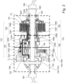
- shows schematically and exemplarily a cross-sectional view of a drive train according to the present disclosure.
- Fig. 3
- shows schematically and exemplarily a cross-sectional view of a partial section of a drive train according to the present disclosure.
- Fig. 4A
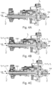
- shows schematically and exemplarily a cross-sectional view of a drive train according to the present disclosure illustrating a torque transmission operation without torque-vectoring.
- Fig. 4B
- shows schematically and exemplarily a cross-section view of a drive train according to the present disclosure illustrating a torque transmission operation with torque-vectoring.
- Fig. 4C
- shows schematically and exemplarily a cross-section view of a drive train according to the present disclosure illustrating a torque transmission operation with torque-vectoring.
- The figures are merely schematic representations and serve only to illustrate examples of the disclosure. Identical or equivalent elements are in principle provided with the same reference signs.
-
Figures 1 and2 show schematically and exemplarily adrive train 100 for a vehicle. Thedrive train 100 comprises a split drive axle 102 having afirst drive shaft 104, here a left drive shaft, and a second drive shaft 106 (seeFigure 2 ), here a right drive shaft. Furthermore, thedrive train 100 comprises aninput gear 108, a differential gear unit 110, afirst transmission unit 112, and a second transmission unit 114 (see alsoFigure 2 ). It can be seen that the differential gear unit 110 is arranged off-centered with regard to a center of the split drive axle 102. Consequently, a distance from the differential gear unit to asecond drive wheel 106 is larger than a distance from the differential gear unit to a first wheel. Thus, in order to have thefirst drive shaft 104 and thesecond drive shaft 106 of similar length, thesecond drive shaft 106 is coupled to the differential gear unit via an intermediate shaft 1061 (see, for exampleFigure 1 ). - The
input gear 108 is a torque input member, which is couplable to a drive unit of the vehicle (not illustrated) for providing an input torque Tin to the differential gear unit 110. The differential gear unit 110 is configured to distribute the input torque Tin on thefirst drive shaft 104 and thesecond drive shaft 106, wherein the differential gear unit 110 unites a torque-transferring function and a torque-vectoring function. Therefore, the differential gear unit 110 comprises adistribution gear box 116, aninternal gear 118 and anexternal gear 120. - The
distribution gear box 116 is coupled to theinput gear 108 in torque-transmitting manner and functions as a traditional differential. Thus, thedistribution gear box 116 is configured to distribute a first portion T1 of the input torque Tin evenly between thefirst drive shaft 104 and the second drive shaft 106 (see alsoFigures 4A to 4C ). Theinternal gear 118 is coupled to theinput gear 108 in a torque-transmitting manner, e.g. via press fitting theinternal gear 118 to theinput gear 108, for providing a second portion T2 of the input torque Tin (see alsoFigure 4C ). Theexternal gear 120 is coupled to theinput gear 108 in a torque-transmitting manner, here by being connected to ahousing 122 of thedistribution gear box 116 through a spline, for providing a third portion T3 of the input torque Tin (see alsoFigure 4B ). - The
first transmission unit 112 comprises a firsttransmission gear assembly 124 having a first transmission ratio R1 and afirst clutch 126, wherein the firsttransmission gear assembly 124 connects theinternal gear 118 of the differential gear unit 110 and the first clutch 126 in a torque-transmitting manner. Thefirst clutch 126 is configured to transmit a torque T2' to the second drive shaft 106 (here via the intermediate shaft 1061), when being in an at least partly closed or partly engaged state, wherein the torque T2' substantially corresponds to the second portion T2 of the input torque Tin being transmitted by the firsttransmission gear assembly 124 having the first transmission ratio R1. In particular, the first transmission ratio R1 may be smaller than 1. Thefirst clutch 126 is exemplarily designed as a friction clutch, particularly as a multi-disc clutch. Thus, theinternal gear 118 and thefirst transmission unit 112 form a first vectoring path P1. - The
second transmission unit 114 comprises a secondtransmission gear assembly 128 having a second transmission ratio R2 and asecond clutch 130, wherein the secondtransmission gear assembly 128 connects theexternal gear 120 of the differential gear unit 110 and thesecond clutch 130 in a torque-transmitting manner. Thesecond clutch 130 is configured to transmit a torque T3' to the second drive shaft 106 (here via the intermediate shaft 1061), when being in an at least partly closed or partly engaged state, wherein the torque T3' substantially corresponds to the third portion T3 of the input torque Tin being transmitted by the secondtransmission gear assembly 128 having the second transmission ratio R2. In particular, the second transmission ratio R2 may be smaller than 1. Thesecond clutch 130 is exemplarily designed as a friction clutch, particularly as a multi-disc clutch. Thus, theexternal gear 120 and thesecond transmission unit 114 form a second vectoring path P2. - In detail, the first
transmission gear assembly 124 comprises afirst input shaft 1241 having afirst input gear 1242 and asecond input gear 1243, and afirst output shaft 1244 having anoutput gear 1245. Thefirst input gear 1242 meshes with the internal gear 119 of the differential gear unit 110. Thesecond input gear 1243 meshes with theoutput gear 1245 of thefirst output shaft 1244, and thefirst output shaft 1244 is rotatably coupled to aninput member 1261 of thefirst clutch 126. The first clutch 126 further comprises anoutput member 1262, wherein theinput member 1261 and theoutput member 1262 are selectively couplable to provide a torque transmission between theinput member 1261 and theoutput member 1262 in the at least partly closed state of thefirst clutch 126, and to prevent torque transmission between theinput member 1261 and theoutput member 1262 in an open state of thefirst clutch 126. Theoutput member 1262 is rotatably coupled to thesecond drive shaft 106. - In other words, in case the
first clutch 126 being a multi-disc clutch, theinput member 1261 may correspond to an inner disc carrier and theoutput member 1262 may correspond to an outer disc carrier or vice versa. - Analogously, the second
transmission gear assembly 128 comprises a second input shaft 1281 having a first input gear 1282 and asecond input gear 1283, and afirst output shaft 1284 having anoutput gear 1285. The first input gear 1282 meshes with theexternal gear 120 of the differential gear unit 110. Thesecond input gear 1283 meshes with theoutput gear 1285 of thesecond output shaft 1284, and thesecond output shaft 1284 is rotatably coupled to aninput member 1301 of thesecond clutch 130. Thesecond clutch 130 further comprises anoutput member 1302, wherein theinput member 1301 and theoutput member 1302 are selectively couplable to provide a torque transmission between theinput member 1301 and theoutput member 1302 in the at least partly closed state of thesecond clutch 130, and to prevent torque transmission between theinput member 1301 and theoutput member 1302 in an open state of thesecond clutch 130. Theoutput member 1302 is rotatably coupled to thesecond drive shaft 106. In order to reduce assembly space of thedrive train 100, thefirst input shaft 1241 and the second input shaft 1281 are concentric with each other (see alsoFigure 3 ). Furthermore, thefirst output shaft 1244 and thesecond output shaft 1284 are concentric with each other, and are additionally concentric with thesecond drive shaft 106. - In other words, in case the
second clutch 130 being a multi-disc clutch, theinput member 1301 may correspond to an inner disc carrier and theoutput member 1302 may correspond to an outer disc carrier or vice versa. - Each of the
clutches release bearing clutches contact ball bearing 140, particularly a sealed angular contact ball bearing, is arranged in and constrained to a housing, inFigure 2 exemplarily thehousing space 132. - By arranging the
first transmission unit 112 and thesecond transmission unit 114 on the same side of the split axle 102, an asymmetric assembly of thedrive train 100 is achieved, which allows providing at least two separate housing spaces, namely aclutch housing space 132 and at least one transmission gear housing space 134, which are fluidly separated from each other. Further, as exemplarily shown inFigure 2 , it is possible to divide the transmission gear housing space 134 into at least two transmission gear sub-housing spaces 1341, 1342, which may be fluidly separated from each other. By providing fluidly separatedhousing spaces 132, 134, it is possible to use different types of pf lubricants in each of thehousing spaces 132, 134. Furthermore, it is possible to use dry clutches as thefirst clutch 126 and thesecond clutch 130, thereby preventing a drag torque which occurs when using wet clutches. - An operation of the
drive train 100 will be explained with regard toFigures 4A to 4C . In case, a substantially equal torque distribution between thefirst drive shaft 104 and thesecond drive shaft 106 is required, e.g., while driving straight ahead or when cornering under low speed, no torque-vectoring is required. Therefore, both, thefirst clutch 126 and thesecond clutch 130, are in an open state, in which, theclutches second drive shaft 106. Thus, neither the first vectoring path P1 nor the second vectoring path P2 transmits torque to thesecond drive shaft 106, resulting in the first portion T1 of the input torque Tin substantially corresponding to the input torque Tin. Thus, the first portion T1 of the input torque Tin is substantially evenly distributed to thefirst drive shaft 104 and thesecond drive shaft 106 via thedistribution gear box 116 only. - In case, there is a need to provide more torque to the
first drive shaft 104 than to thesecond drive shaft 106, the first vectoring path P1 is additionally activated (seeFigure 4C ). This means, thefirst clutch 126 is in the at least partly closed state thereby transmitting the torque T2' to thesecond drive shaft 106. In this case, the first portion T1 of the input torque Tin, which is evenly distributed to thefirst drive shaft 104 and thesecond drive shaft 106 by thedistribution gear box 116, substantially corresponds to the input torque Tin minus the second portion T2 of the input torque Tin:
- As mentioned above, the second portion T2 is transmitted to the
second drive shaft 106 with the first transmission ratio R1 resulting in the torque T2' being actually transmitted to the second drive shaft 106:
- Since the first vectoring path P1 comprises one internal gear meshing, namely the
internal gear 118 meshing with thefirst input gear 1242 of the firsttransmission gear assembly 124, and one external gear meshing, namely thesecond input gear 1243 of the firsttransmission gear assembly 124 meshing with theoutput gear 1245 of the firsttransmission gear assembly 124, the direction of the second portion T2 of the input torque Tin is opposite to the direction of the first portion T1. Thus, the first vectoring path P1 subtracts torque, particularly a torque of the amount of torque T2', from thesecond drive shaft 106, resulting in that the torque at thesecond drive shaft 106 is lower than the torque at thefirst drive shaft 104. - In case, there is a need to provide more torque to the
second drive shaft 106 than to thefirst drive shaft 104, the second vectoring path P2 is additionally activated (seeFigure 4B ). This means, thesecond clutch 130 is in the at least partly closed state thereby transmitting the torque T3' to thesecond drive shaft 106. In this case, the first portion T1 of the input torque Tin, which is evenly distributed to thefirst drive shaft 104 and thesecond drive shaft 106 by thedistribution gear box 116, substantially corresponds to the input torque Tin minus the third portion T3 of the input torque Tin:
- As mentioned above, the third portion T3 is transmitted to the
second drive shaft 106 with the second transmission ratio R2 resulting in the torque T3' being actually transmitted to the second drive shaft 106:
- Since the second vectoring path P2 comprises two external gear meshing, namely the
external gear 120 meshing with the first input gear 1282 of the secondtransmission gear assembly 128, and thesecond input gear 1283 of the secondtransmission gear assembly 128 meshing with theoutput gear 1285 of the secondtransmission gear assembly 128, the direction of the third portion T3 of the input torque Tin is the same as the direction of the first portion T1. Thus, the second vectoring path P2 adds torque, particularly a torque of the amount of torque T3', to thesecond drive shaft 106, resulting in that the torque at thesecond drive shaft 106 is higher than the torque at thefirst drive shaft 104. - Further, as mentioned above, the
second drive shaft 106 may be coupled to theintermediate shaft portion 1061 as exemplarily shown inFigures 1 ,2 and4 . Theintermediate shaft 1061 may also be referred as inner ball joint shaft (IBJ shaft) and has at the outer end an inner ball joint (not shown), to which thesecond drive shaft 106 is connected. Thisintermediate shaft portion 1061 has a spline for transmitting the torque from theclutches intermediate shaft portion 1061. Thus, thesecond drive shaft 106 may be a one-piece second drive shaft or may be coupled to theintermediate shaft portion 1061, thereby forming a two-piece second drive shaft. - Other variations to the disclosed examples can be understood and effected by those skilled in the art in practicing the claimed disclosure, from the study of the drawings, the disclosure, and the appended claims. In the claims the word "comprising" does not exclude other elements or steps and the indefinite article "a" or "an" does not exclude a plurality. A single processor or other unit may fulfill the functions of several items or steps recited in the claims. The mere fact that certain measures are recited in mutually different dependent claims does not indicate that a combination of these measures cannot be used to advantage. Any reference signs in the claims should not be construed as limiting the scope of the claims.
-
- 100
- drive train
- 102
- split drive axle
- 104
- first drive shaft
- 106
- second drive shaft
- 1061
- intermediate shaft
- 108
- input gear
- 110
- differential gear unit
- 112
- first transmission unit
- 114
- second transmission unit
- 116
- distribution gear box
- 118
- internal gear
- 120
- external gear
- 122
- housing
- 124
- first transmission gear assembly
- 1241
- first input shaft
- 1242
- first input gear
- 1243
- second input gear
- 1244
- first output shaft
- 1245
- output gear
- 126
- first clutch
- 1261
- inner member
- 1262
- outer member
- 1263
- release bearing
- 128
- second transmission gear assembly
- 1281
- second input shaft
- 1282
- first input gear
- 1283
- second input gear
- 1284
- second output shaft
- 1285
- output gear
- 130
- second clutch
- 1301
- inner member
- 1302
- outer member
- 1303
- release bearing
- 132
- clutch housing space
- 134
- transmission gear housing space
- 1341
- transmission gear sub-housing space
- 1342
- transmission gear sub-housing space
- 140
- angular contact ball bearing
- P1
- first vectoring path
- P2
- second vectoring path
- Tin
- input torque
- T1
- first portion of input torque
- T2
- second portion of input torque
- T3
- third portion of input torque
- T2'
- torque
- T3'
- torque
- R1
- first transmission ratio
- R2
- second transmission ratio
Claims (15)
- A drive train (100) for a vehicle, comprising:a split drive axle (102) having a first drive shaft (104) being couplable to a first wheel and a second drive shaft (106) being couplable to a second wheel,an input gear (108) being couplable to a drive unit of the vehicle for providing an input torque (Tin) to a differential gear unit (110),the differential gear unit (110) being configured to distribute the input torque (Tin) on the first drive shaft (104) and the second drive shaft (106), the differential gear unit (110) comprising:a distribution gear box (116) being coupled to the input gear (108) in a torque-transmitting manner and configured to distribute a first portion (T1) of the input torque (Tin) evenly between the first drive shaft (104) and the second drive shaft (106),an internal gear (118) being coupled to the input gear (108) in a torque-transmitting manner for providing a second portion (T2) of the input torque (Tin), andan external gear (120) being coupled to the input gear (108) in a torque-transmitting manner for providing a third portion (T3) of the input torque (Tin),a first transmission unit (112) comprising a first transmission gear assembly (124) and a first clutch (126),the first transmission gear assembly (124) being configured to connect the internal gear (118) of the differential gear unit (110) and the first clutch (126) in a torque-transmitting manner, andthe first clutch (126) being configured to transmit the second portion (T2) of the input torque (Tin) to the second drive shaft (106), when being in an at least partly closed state,a second transmission unit (114) comprising a second transmission gear assembly (128) and a second clutch (130),the second transmission gear assembly (128) being configured to connect the external gear (120) of the differential gear unit (110) and the second clutch (130) in a torque-transmitting manner, andthe second clutch (130) being configured to transmit the third portion (T3) of the input torque (Tin) to the second drive shaft (106), when being in an at least partly closed state,wherein the input torque (Tin) corresponds to a sum of the first portion (T1) of the input torque (Tin) and the second portion (T2) of the input torque (Tin) or a sum of the first portion (T1) of the input torque (Tin) and the third portion (T3) of the input torque (Tin).
- The drive train (100) according to claim 1, the second portion (T2) of the input torque (Tin) corresponding to a torque in a direction opposite to the direction of first portion (T1) of the input torque (Tin).
- The drive train (100) according to claim 1 or 2, the third portion (T3) of the input torque (Tin) corresponding to a torque in the same direction as the first portion (T1) of the input torque (Tin).
- The drive train (100) according to any of claims 1 to 3, further comprising a housing (122) having a clutch housing space (132) for accommodating the first clutch (126) and the second clutch (130), and a transmission gear housing space (134) for accommodating the first transmission gear assembly (124) and the second transmission gear assembly (128), the clutch housing space (132) and the transmission gear housing space (134) being fluidly separated from each other.
- The drive train (100) according to any of claims 1 to 4, the first clutch (126) and the second clutch (130) each being a dry clutch.
- The drive train (100) according to any of claims 1 to 5, the first transmission gear assembly (124) comprising a first input shaft (1241) having a first input gear (1242) and a second input gear (1243), and a first output shaft (1244) having an output gear (1245), wherein the first input gear (1242) of the first input shaft (1241) is configured to mesh with the internal gear (118) of the differential gear unit (110), and the second input gear (1243) of the first input shaft (1241) is configured to mesh with the output gear (1245) of the first output shaft (1244).
- The drive train (100) according to claim 6, the first clutch (126) having an input member (1261) and an output member (1262), the input member (1261) and the output member (1262) being configured to be selectively couplable to provide a torque transmission between the input member (1261) and the output member (1262) in the at least partly closed state of the first clutch (126) and to prevent torque transmission between the input member (1261) and the output member (1262) in an open state of the first clutch (126), wherein the input member (1261) is coupled to the first output shaft (1244), and the output member (1262) is coupled to the second drive shaft (106).
- The drive train (100) according to any of claims 1 to 7, the second transmission gear assembly (128) comprising a second input shaft (1281) having a first input gear (1282) and a second input gear (1283), and a second output shaft (1284) having an output gear (1285), wherein the first input gear (1282) of the second input shaft (1281) is configured to mesh with the external gear (120) of the differential gear unit (110), and the second input gear (1283) of the second input shaft (1281) is configured to mesh with the output gear (1285) of the second output shaft (1284).
- The drive train (100) according to claim 8, the second clutch (130) having an input member (1301) and an output member (1302), the input member (1301) and the output member (1302) being configured to be selectively couplable to provide a torque transmission between the input member (1301) and the output member (1302) in the at least partly closed state of the second clutch (130) and to prevent torque transmission between the input member (1301) and the output member (1302) in an open state of the second clutch (130), wherein the input member (1301) is coupled to the second output shaft (1284), and the output member (1302) is coupled to the second drive shaft (106).
- The drive train (100) according to any of claims 1 to 9, the internal gear (118) being integrally formed with the input gear (108).
- The drive train (100) according to any of claims 1 to 10, the external gear (120) being integrally formed with the differential gear box (116).
- The drive train (100) according to any of claims 8 to 11, the first input shaft (1241) and the second input shaft (1281) being co-axially arranged to each other and/or the first output shaft (1264) and the second output shaft (1284) being co-axially arranged to each other.
- The drive train (100) according to any of claims 1 to 12, the first clutch (126) and the second clutch (130) being co-axially arranged to each other.
- The drive train (100) according to any of claims 1 to 13, the second drive shaft (106) is coupled to the differential gear box (116) via an intermediate shaft portion (1061).
- A vehicle comprising a drive train (100) according to any of claims 1 to 14.
Priority Applications (1)
| Application Number | Priority Date | Filing Date | Title |
|---|---|---|---|
| EP23175077.9A EP4467844B1 (en) | 2023-05-24 | 2023-05-24 | Drive train for vehicle and vehicle |
Applications Claiming Priority (1)
| Application Number | Priority Date | Filing Date | Title |
|---|---|---|---|
| EP23175077.9A EP4467844B1 (en) | 2023-05-24 | 2023-05-24 | Drive train for vehicle and vehicle |
Publications (2)
| Publication Number | Publication Date |
|---|---|
| EP4467844A1 true EP4467844A1 (en) | 2024-11-27 |
| EP4467844B1 EP4467844B1 (en) | 2025-07-09 |
Family
ID=86603846
Family Applications (1)
| Application Number | Title | Priority Date | Filing Date |
|---|---|---|---|
| EP23175077.9A Active EP4467844B1 (en) | 2023-05-24 | 2023-05-24 | Drive train for vehicle and vehicle |
Country Status (1)
| Country | Link |
|---|---|
| EP (1) | EP4467844B1 (en) |
Citations (6)
| Publication number | Priority date | Publication date | Assignee | Title |
|---|---|---|---|---|
| EP0844416A2 (en) * | 1996-11-22 | 1998-05-27 | Kenji Mimura | Differential gear |
| US20050159264A1 (en) * | 2003-03-07 | 2005-07-21 | Dumitru Puiu | Torque vectoring drive units with worm driven ball screw clutches |
| DE102008039928A1 (en) * | 2008-08-27 | 2010-03-04 | Magna Powertrain Ag & Co Kg | Differential gear unit for use with active control of torque distribution, particularly at front axle of motor vehicle, has input element propelled to rotating motion and differential gear coupled with input element |
| US20160263995A1 (en) * | 2015-03-13 | 2016-09-15 | Toyota Jidosha Kabushiki Kaisha | Differential device of four-wheel drive vehicle |
| DE102015216668A1 (en) * | 2015-09-01 | 2017-03-02 | Schaeffler Technologies AG & Co. KG | Transmission device for a motor vehicle |
| US20170211676A1 (en) * | 2016-01-21 | 2017-07-27 | Dana Automotive Systems Group, Llc. | Torque vectoring unit |
-
2023
- 2023-05-24 EP EP23175077.9A patent/EP4467844B1/en active Active
Patent Citations (6)
| Publication number | Priority date | Publication date | Assignee | Title |
|---|---|---|---|---|
| EP0844416A2 (en) * | 1996-11-22 | 1998-05-27 | Kenji Mimura | Differential gear |
| US20050159264A1 (en) * | 2003-03-07 | 2005-07-21 | Dumitru Puiu | Torque vectoring drive units with worm driven ball screw clutches |
| DE102008039928A1 (en) * | 2008-08-27 | 2010-03-04 | Magna Powertrain Ag & Co Kg | Differential gear unit for use with active control of torque distribution, particularly at front axle of motor vehicle, has input element propelled to rotating motion and differential gear coupled with input element |
| US20160263995A1 (en) * | 2015-03-13 | 2016-09-15 | Toyota Jidosha Kabushiki Kaisha | Differential device of four-wheel drive vehicle |
| DE102015216668A1 (en) * | 2015-09-01 | 2017-03-02 | Schaeffler Technologies AG & Co. KG | Transmission device for a motor vehicle |
| US20170211676A1 (en) * | 2016-01-21 | 2017-07-27 | Dana Automotive Systems Group, Llc. | Torque vectoring unit |
Also Published As
| Publication number | Publication date |
|---|---|
| EP4467844B1 (en) | 2025-07-09 |
Similar Documents
| Publication | Publication Date | Title |
|---|---|---|
| US20200346544A1 (en) | All-wheel drive with disconnect system | |
| US10094457B2 (en) | Electric all-wheel drive two speed with split double reduction planetary | |
| US5046998A (en) | Two-wheel drive mode for full-time transfer case | |
| US8827859B2 (en) | Differential having two-piece case split through planetary carrier wall | |
| US9068631B2 (en) | Automatic transmission | |
| EP4077007B1 (en) | A gearbox for an electric powertrain | |
| US10415679B2 (en) | Electric all-wheel drive two speed with split double reduction planetary | |
| EP1527938A2 (en) | Electronically-controlled rear drive module for all-wheel drive vehicle | |
| US11949319B2 (en) | Multi-speed gearbox and the drive axle made therewith | |
| US20170227103A1 (en) | Torque vectoring differential | |
| US7448977B2 (en) | Motor vehicle transaxle having a differential mechanism controlled by an on-demand clutch | |
| JPS6349526A (en) | Vehicle power transmission mechanism | |
| US4862768A (en) | Limiting/switching device for four wheel drive vehicle | |
| US10040346B2 (en) | Power transfer unit (PTU) assembly with hydraulically actuated disconnect rear output shaft | |
| EP4467844B1 (en) | Drive train for vehicle and vehicle | |
| US4790211A (en) | Power transmission device for four wheel drive vehicle having an improved differential motion limiting mechanism | |
| CN100476244C (en) | automatic transmission | |
| CN111720495A (en) | Main reducing gear and vehicle | |
| JPWO2004061332A1 (en) | Automatic transmission | |
| US10406915B2 (en) | Rear drive unit clutch assembly | |
| CN217598350U (en) | Double clutch, electric drive assembly, four-wheel drive system and vehicle | |
| CN217271743U (en) | Transfer case of integrated oil pump | |
| US20260043472A1 (en) | Work vehicle and drive unit for work vehicle | |
| JP6369481B2 (en) | Powertrain structure |
Legal Events
| Date | Code | Title | Description |
|---|---|---|---|
| PUAI | Public reference made under article 153(3) epc to a published international application that has entered the european phase |
Free format text: ORIGINAL CODE: 0009012 |
|
| STAA | Information on the status of an ep patent application or granted ep patent |
Free format text: STATUS: REQUEST FOR EXAMINATION WAS MADE |
|
| STAA | Information on the status of an ep patent application or granted ep patent |
Free format text: STATUS: EXAMINATION IS IN PROGRESS |
|
| 17P | Request for examination filed |
Effective date: 20240213 |
|
| AK | Designated contracting states |
Kind code of ref document: A1 Designated state(s): AL AT BE BG CH CY CZ DE DK EE ES FI FR GB GR HR HU IE IS IT LI LT LU LV MC ME MK MT NL NO PL PT RO RS SE SI SK SM TR |
|
| 17Q | First examination report despatched |
Effective date: 20241108 |
|
| GRAP | Despatch of communication of intention to grant a patent |
Free format text: ORIGINAL CODE: EPIDOSNIGR1 |
|
| STAA | Information on the status of an ep patent application or granted ep patent |
Free format text: STATUS: GRANT OF PATENT IS INTENDED |
|
| INTG | Intention to grant announced |
Effective date: 20250113 |
|
| GRAS | Grant fee paid |
Free format text: ORIGINAL CODE: EPIDOSNIGR3 |
|
| GRAA | (expected) grant |
Free format text: ORIGINAL CODE: 0009210 |
|
| STAA | Information on the status of an ep patent application or granted ep patent |
Free format text: STATUS: THE PATENT HAS BEEN GRANTED |
|
| AK | Designated contracting states |
Kind code of ref document: B1 Designated state(s): AL AT BE BG CH CY CZ DE DK EE ES FI FR GB GR HR HU IE IS IT LI LT LU LV MC ME MK MT NL NO PL PT RO RS SE SI SK SM TR |
|
| REG | Reference to a national code |
Ref country code: GB Ref legal event code: FG4D |
|
| REG | Reference to a national code |
Ref country code: CH Ref legal event code: EP |
|
| P01 | Opt-out of the competence of the unified patent court (upc) registered |
Free format text: CASE NUMBER: APP_28628/2025 Effective date: 20250616 |
|
| REG | Reference to a national code |
Ref country code: IE Ref legal event code: FG4D |
|
| REG | Reference to a national code |
Ref country code: DE Ref legal event code: R096 Ref document number: 602023004642 Country of ref document: DE |
|
| REG | Reference to a national code |
Ref country code: NL Ref legal event code: MP Effective date: 20250709 |
|
| PG25 | Lapsed in a contracting state [announced via postgrant information from national office to epo] |
Ref country code: PT Free format text: LAPSE BECAUSE OF FAILURE TO SUBMIT A TRANSLATION OF THE DESCRIPTION OR TO PAY THE FEE WITHIN THE PRESCRIBED TIME-LIMIT Effective date: 20251110 |
|
| PG25 | Lapsed in a contracting state [announced via postgrant information from national office to epo] |
Ref country code: NL Free format text: LAPSE BECAUSE OF FAILURE TO SUBMIT A TRANSLATION OF THE DESCRIPTION OR TO PAY THE FEE WITHIN THE PRESCRIBED TIME-LIMIT Effective date: 20250709 |
|
| REG | Reference to a national code |
Ref country code: AT Ref legal event code: MK05 Ref document number: 1812065 Country of ref document: AT Kind code of ref document: T Effective date: 20250709 |
|
| PG25 | Lapsed in a contracting state [announced via postgrant information from national office to epo] |
Ref country code: IS Free format text: LAPSE BECAUSE OF FAILURE TO SUBMIT A TRANSLATION OF THE DESCRIPTION OR TO PAY THE FEE WITHIN THE PRESCRIBED TIME-LIMIT Effective date: 20251109 |
|
| PG25 | Lapsed in a contracting state [announced via postgrant information from national office to epo] |
Ref country code: NO Free format text: LAPSE BECAUSE OF FAILURE TO SUBMIT A TRANSLATION OF THE DESCRIPTION OR TO PAY THE FEE WITHIN THE PRESCRIBED TIME-LIMIT Effective date: 20251009 |
|
| REG | Reference to a national code |
Ref country code: LT Ref legal event code: MG9D |
|
| PG25 | Lapsed in a contracting state [announced via postgrant information from national office to epo] |
Ref country code: AT Free format text: LAPSE BECAUSE OF FAILURE TO SUBMIT A TRANSLATION OF THE DESCRIPTION OR TO PAY THE FEE WITHIN THE PRESCRIBED TIME-LIMIT Effective date: 20250709 |
|
| PG25 | Lapsed in a contracting state [announced via postgrant information from national office to epo] |
Ref country code: FI Free format text: LAPSE BECAUSE OF FAILURE TO SUBMIT A TRANSLATION OF THE DESCRIPTION OR TO PAY THE FEE WITHIN THE PRESCRIBED TIME-LIMIT Effective date: 20250709 |
|
| PG25 | Lapsed in a contracting state [announced via postgrant information from national office to epo] |
Ref country code: HR Free format text: LAPSE BECAUSE OF FAILURE TO SUBMIT A TRANSLATION OF THE DESCRIPTION OR TO PAY THE FEE WITHIN THE PRESCRIBED TIME-LIMIT Effective date: 20250709 |
|
| PG25 | Lapsed in a contracting state [announced via postgrant information from national office to epo] |
Ref country code: GR Free format text: LAPSE BECAUSE OF FAILURE TO SUBMIT A TRANSLATION OF THE DESCRIPTION OR TO PAY THE FEE WITHIN THE PRESCRIBED TIME-LIMIT Effective date: 20251010 |
|
| PG25 | Lapsed in a contracting state [announced via postgrant information from national office to epo] |
Ref country code: SE Free format text: LAPSE BECAUSE OF FAILURE TO SUBMIT A TRANSLATION OF THE DESCRIPTION OR TO PAY THE FEE WITHIN THE PRESCRIBED TIME-LIMIT Effective date: 20250709 |
|
| PG25 | Lapsed in a contracting state [announced via postgrant information from national office to epo] |
Ref country code: LV Free format text: LAPSE BECAUSE OF FAILURE TO SUBMIT A TRANSLATION OF THE DESCRIPTION OR TO PAY THE FEE WITHIN THE PRESCRIBED TIME-LIMIT Effective date: 20250709 |
|
| PG25 | Lapsed in a contracting state [announced via postgrant information from national office to epo] |
Ref country code: PL Free format text: LAPSE BECAUSE OF FAILURE TO SUBMIT A TRANSLATION OF THE DESCRIPTION OR TO PAY THE FEE WITHIN THE PRESCRIBED TIME-LIMIT Effective date: 20250709 Ref country code: BG Free format text: LAPSE BECAUSE OF FAILURE TO SUBMIT A TRANSLATION OF THE DESCRIPTION OR TO PAY THE FEE WITHIN THE PRESCRIBED TIME-LIMIT Effective date: 20250709 |
|
| PG25 | Lapsed in a contracting state [announced via postgrant information from national office to epo] |
Ref country code: RS Free format text: LAPSE BECAUSE OF FAILURE TO SUBMIT A TRANSLATION OF THE DESCRIPTION OR TO PAY THE FEE WITHIN THE PRESCRIBED TIME-LIMIT Effective date: 20251009 |
|
| PG25 | Lapsed in a contracting state [announced via postgrant information from national office to epo] |
Ref country code: ES Free format text: LAPSE BECAUSE OF FAILURE TO SUBMIT A TRANSLATION OF THE DESCRIPTION OR TO PAY THE FEE WITHIN THE PRESCRIBED TIME-LIMIT Effective date: 20250709 |
|
| PG25 | Lapsed in a contracting state [announced via postgrant information from national office to epo] |
Ref country code: SM Free format text: LAPSE BECAUSE OF FAILURE TO SUBMIT A TRANSLATION OF THE DESCRIPTION OR TO PAY THE FEE WITHIN THE PRESCRIBED TIME-LIMIT Effective date: 20250709 |
|
| PG25 | Lapsed in a contracting state [announced via postgrant information from national office to epo] |
Ref country code: DK Free format text: LAPSE BECAUSE OF FAILURE TO SUBMIT A TRANSLATION OF THE DESCRIPTION OR TO PAY THE FEE WITHIN THE PRESCRIBED TIME-LIMIT Effective date: 20250709 |
|
| PG25 | Lapsed in a contracting state [announced via postgrant information from national office to epo] |
Ref country code: IT Free format text: LAPSE BECAUSE OF FAILURE TO SUBMIT A TRANSLATION OF THE DESCRIPTION OR TO PAY THE FEE WITHIN THE PRESCRIBED TIME-LIMIT Effective date: 20250709 |
|
| PG25 | Lapsed in a contracting state [announced via postgrant information from national office to epo] |
Ref country code: CZ Free format text: LAPSE BECAUSE OF FAILURE TO SUBMIT A TRANSLATION OF THE DESCRIPTION OR TO PAY THE FEE WITHIN THE PRESCRIBED TIME-LIMIT Effective date: 20250709 |
|
| PG25 | Lapsed in a contracting state [announced via postgrant information from national office to epo] |
Ref country code: SK Free format text: LAPSE BECAUSE OF FAILURE TO SUBMIT A TRANSLATION OF THE DESCRIPTION OR TO PAY THE FEE WITHIN THE PRESCRIBED TIME-LIMIT Effective date: 20250709 Ref country code: EE Free format text: LAPSE BECAUSE OF FAILURE TO SUBMIT A TRANSLATION OF THE DESCRIPTION OR TO PAY THE FEE WITHIN THE PRESCRIBED TIME-LIMIT Effective date: 20250709 |
|
| PLBE | No opposition filed within time limit |
Free format text: ORIGINAL CODE: 0009261 |
|
| STAA | Information on the status of an ep patent application or granted ep patent |
Free format text: STATUS: NO OPPOSITION FILED WITHIN TIME LIMIT |