EP4467838A1 - Air spring, vibration isolation device, sensor assembly, vibration isolation control method, and vehicle - Google Patents
Air spring, vibration isolation device, sensor assembly, vibration isolation control method, and vehicle Download PDFInfo
- Publication number
- EP4467838A1 EP4467838A1 EP22926515.2A EP22926515A EP4467838A1 EP 4467838 A1 EP4467838 A1 EP 4467838A1 EP 22926515 A EP22926515 A EP 22926515A EP 4467838 A1 EP4467838 A1 EP 4467838A1
- Authority
- EP
- European Patent Office
- Prior art keywords
- air
- air chamber
- air spring
- airway
- spring
- Prior art date
- Legal status (The legal status is an assumption and is not a legal conclusion. Google has not performed a legal analysis and makes no representation as to the accuracy of the status listed.)
- Pending
Links
Images





Classifications
-
- F—MECHANICAL ENGINEERING; LIGHTING; HEATING; WEAPONS; BLASTING
- F16—ENGINEERING ELEMENTS AND UNITS; GENERAL MEASURES FOR PRODUCING AND MAINTAINING EFFECTIVE FUNCTIONING OF MACHINES OR INSTALLATIONS; THERMAL INSULATION IN GENERAL
- F16F—SPRINGS; SHOCK-ABSORBERS; MEANS FOR DAMPING VIBRATION
- F16F15/00—Suppression of vibrations in systems; Means or arrangements for avoiding or reducing out-of-balance forces, e.g. due to motion
- F16F15/02—Suppression of vibrations of non-rotating, e.g. reciprocating systems; Suppression of vibrations of rotating systems by use of members not moving with the rotating systems
- F16F15/023—Suppression of vibrations of non-rotating, e.g. reciprocating systems; Suppression of vibrations of rotating systems by use of members not moving with the rotating systems using fluid means
- F16F15/027—Suppression of vibrations of non-rotating, e.g. reciprocating systems; Suppression of vibrations of rotating systems by use of members not moving with the rotating systems using fluid means comprising control arrangements
- F16F15/0275—Control of stiffness
-
- B—PERFORMING OPERATIONS; TRANSPORTING
- B60—VEHICLES IN GENERAL
- B60R—VEHICLES, VEHICLE FITTINGS, OR VEHICLE PARTS, NOT OTHERWISE PROVIDED FOR
- B60R11/00—Arrangements for holding or mounting articles, not otherwise provided for
-
- F—MECHANICAL ENGINEERING; LIGHTING; HEATING; WEAPONS; BLASTING
- F16—ENGINEERING ELEMENTS AND UNITS; GENERAL MEASURES FOR PRODUCING AND MAINTAINING EFFECTIVE FUNCTIONING OF MACHINES OR INSTALLATIONS; THERMAL INSULATION IN GENERAL
- F16F—SPRINGS; SHOCK-ABSORBERS; MEANS FOR DAMPING VIBRATION
- F16F15/00—Suppression of vibrations in systems; Means or arrangements for avoiding or reducing out-of-balance forces, e.g. due to motion
- F16F15/02—Suppression of vibrations of non-rotating, e.g. reciprocating systems; Suppression of vibrations of rotating systems by use of members not moving with the rotating systems
- F16F15/023—Suppression of vibrations of non-rotating, e.g. reciprocating systems; Suppression of vibrations of rotating systems by use of members not moving with the rotating systems using fluid means
- F16F15/0232—Suppression of vibrations of non-rotating, e.g. reciprocating systems; Suppression of vibrations of rotating systems by use of members not moving with the rotating systems using fluid means with at least one gas spring
-
- F—MECHANICAL ENGINEERING; LIGHTING; HEATING; WEAPONS; BLASTING
- F16—ENGINEERING ELEMENTS AND UNITS; GENERAL MEASURES FOR PRODUCING AND MAINTAINING EFFECTIVE FUNCTIONING OF MACHINES OR INSTALLATIONS; THERMAL INSULATION IN GENERAL
- F16F—SPRINGS; SHOCK-ABSORBERS; MEANS FOR DAMPING VIBRATION
- F16F9/00—Springs, vibration-dampers, shock-absorbers, or similarly-constructed movement-dampers using a fluid or the equivalent as damping medium
- F16F9/02—Springs, vibration-dampers, shock-absorbers, or similarly-constructed movement-dampers using a fluid or the equivalent as damping medium using gas only or vacuum
- F16F9/04—Springs, vibration-dampers, shock-absorbers, or similarly-constructed movement-dampers using a fluid or the equivalent as damping medium using gas only or vacuum in a chamber with a flexible wall
- F16F9/0418—Springs, vibration-dampers, shock-absorbers, or similarly-constructed movement-dampers using a fluid or the equivalent as damping medium using gas only or vacuum in a chamber with a flexible wall having a particular shape, e.g. annular, spherical, tube-like
-
- F—MECHANICAL ENGINEERING; LIGHTING; HEATING; WEAPONS; BLASTING
- F16—ENGINEERING ELEMENTS AND UNITS; GENERAL MEASURES FOR PRODUCING AND MAINTAINING EFFECTIVE FUNCTIONING OF MACHINES OR INSTALLATIONS; THERMAL INSULATION IN GENERAL
- F16F—SPRINGS; SHOCK-ABSORBERS; MEANS FOR DAMPING VIBRATION
- F16F9/00—Springs, vibration-dampers, shock-absorbers, or similarly-constructed movement-dampers using a fluid or the equivalent as damping medium
- F16F9/02—Springs, vibration-dampers, shock-absorbers, or similarly-constructed movement-dampers using a fluid or the equivalent as damping medium using gas only or vacuum
- F16F9/04—Springs, vibration-dampers, shock-absorbers, or similarly-constructed movement-dampers using a fluid or the equivalent as damping medium using gas only or vacuum in a chamber with a flexible wall
- F16F9/049—Springs, vibration-dampers, shock-absorbers, or similarly-constructed movement-dampers using a fluid or the equivalent as damping medium using gas only or vacuum in a chamber with a flexible wall multi-chamber units
-
- F—MECHANICAL ENGINEERING; LIGHTING; HEATING; WEAPONS; BLASTING
- F16—ENGINEERING ELEMENTS AND UNITS; GENERAL MEASURES FOR PRODUCING AND MAINTAINING EFFECTIVE FUNCTIONING OF MACHINES OR INSTALLATIONS; THERMAL INSULATION IN GENERAL
- F16F—SPRINGS; SHOCK-ABSORBERS; MEANS FOR DAMPING VIBRATION
- F16F9/00—Springs, vibration-dampers, shock-absorbers, or similarly-constructed movement-dampers using a fluid or the equivalent as damping medium
- F16F9/32—Details
- F16F9/3292—Sensor arrangements
-
- F—MECHANICAL ENGINEERING; LIGHTING; HEATING; WEAPONS; BLASTING
- F16—ENGINEERING ELEMENTS AND UNITS; GENERAL MEASURES FOR PRODUCING AND MAINTAINING EFFECTIVE FUNCTIONING OF MACHINES OR INSTALLATIONS; THERMAL INSULATION IN GENERAL
- F16F—SPRINGS; SHOCK-ABSORBERS; MEANS FOR DAMPING VIBRATION
- F16F9/00—Springs, vibration-dampers, shock-absorbers, or similarly-constructed movement-dampers using a fluid or the equivalent as damping medium
- F16F9/32—Details
- F16F9/50—Special means providing automatic damping adjustment, i.e. self-adjustment of damping by particular sliding movements of a valve element, other than flexions or displacement of valve discs; Special means providing self-adjustment of spring characteristics
-
- G—PHYSICS
- G01—MEASURING; TESTING
- G01S—RADIO DIRECTION-FINDING; RADIO NAVIGATION; DETERMINING DISTANCE OR VELOCITY BY USE OF RADIO WAVES; LOCATING OR PRESENCE-DETECTING BY USE OF THE REFLECTION OR RERADIATION OF RADIO WAVES; ANALOGOUS ARRANGEMENTS USING OTHER WAVES
- G01S7/00—Details of systems according to groups G01S13/00, G01S15/00, G01S17/00
- G01S7/02—Details of systems according to groups G01S13/00, G01S15/00, G01S17/00 of systems according to group G01S13/00
- G01S7/027—Constructional details of housings, e.g. form, type, material or ruggedness
-
- B—PERFORMING OPERATIONS; TRANSPORTING
- B60—VEHICLES IN GENERAL
- B60R—VEHICLES, VEHICLE FITTINGS, OR VEHICLE PARTS, NOT OTHERWISE PROVIDED FOR
- B60R19/00—Wheel guards; Radiator guards, e.g. grilles; Obstruction removers; Fittings damping bouncing force in collisions
- B60R19/02—Bumpers, i.e. impact receiving or absorbing members for protecting vehicles or fending off blows from other vehicles or objects
- B60R19/48—Bumpers, i.e. impact receiving or absorbing members for protecting vehicles or fending off blows from other vehicles or objects combined with, or convertible into, other devices or objects, e.g. bumpers combined with road brushes, bumpers convertible into beds
- B60R19/483—Bumpers, i.e. impact receiving or absorbing members for protecting vehicles or fending off blows from other vehicles or objects combined with, or convertible into, other devices or objects, e.g. bumpers combined with road brushes, bumpers convertible into beds with obstacle sensors of electric or electronic type
-
- B—PERFORMING OPERATIONS; TRANSPORTING
- B60—VEHICLES IN GENERAL
- B60R—VEHICLES, VEHICLE FITTINGS, OR VEHICLE PARTS, NOT OTHERWISE PROVIDED FOR
- B60R11/00—Arrangements for holding or mounting articles, not otherwise provided for
- B60R2011/0001—Arrangements for holding or mounting articles, not otherwise provided for characterised by position
- B60R2011/004—Arrangements for holding or mounting articles, not otherwise provided for characterised by position outside the vehicle
-
- F—MECHANICAL ENGINEERING; LIGHTING; HEATING; WEAPONS; BLASTING
- F16—ENGINEERING ELEMENTS AND UNITS; GENERAL MEASURES FOR PRODUCING AND MAINTAINING EFFECTIVE FUNCTIONING OF MACHINES OR INSTALLATIONS; THERMAL INSULATION IN GENERAL
- F16F—SPRINGS; SHOCK-ABSORBERS; MEANS FOR DAMPING VIBRATION
- F16F2222/00—Special physical effects, e.g. nature of damping effects
- F16F2222/12—Fluid damping
- F16F2222/126—Fluid damping using gases
-
- F—MECHANICAL ENGINEERING; LIGHTING; HEATING; WEAPONS; BLASTING
- F16—ENGINEERING ELEMENTS AND UNITS; GENERAL MEASURES FOR PRODUCING AND MAINTAINING EFFECTIVE FUNCTIONING OF MACHINES OR INSTALLATIONS; THERMAL INSULATION IN GENERAL
- F16F—SPRINGS; SHOCK-ABSORBERS; MEANS FOR DAMPING VIBRATION
- F16F2228/00—Functional characteristics, e.g. variability, frequency-dependence
- F16F2228/06—Stiffness
- F16F2228/066—Variable stiffness
-
- F—MECHANICAL ENGINEERING; LIGHTING; HEATING; WEAPONS; BLASTING
- F16—ENGINEERING ELEMENTS AND UNITS; GENERAL MEASURES FOR PRODUCING AND MAINTAINING EFFECTIVE FUNCTIONING OF MACHINES OR INSTALLATIONS; THERMAL INSULATION IN GENERAL
- F16F—SPRINGS; SHOCK-ABSORBERS; MEANS FOR DAMPING VIBRATION
- F16F2230/00—Purpose; Design features
- F16F2230/08—Sensor arrangement
-
- F—MECHANICAL ENGINEERING; LIGHTING; HEATING; WEAPONS; BLASTING
- F16—ENGINEERING ELEMENTS AND UNITS; GENERAL MEASURES FOR PRODUCING AND MAINTAINING EFFECTIVE FUNCTIONING OF MACHINES OR INSTALLATIONS; THERMAL INSULATION IN GENERAL
- F16F—SPRINGS; SHOCK-ABSORBERS; MEANS FOR DAMPING VIBRATION
- F16F2230/00—Purpose; Design features
- F16F2230/36—Holes, slots or the like
-
- G—PHYSICS
- G01—MEASURING; TESTING
- G01S—RADIO DIRECTION-FINDING; RADIO NAVIGATION; DETERMINING DISTANCE OR VELOCITY BY USE OF RADIO WAVES; LOCATING OR PRESENCE-DETECTING BY USE OF THE REFLECTION OR RERADIATION OF RADIO WAVES; ANALOGOUS ARRANGEMENTS USING OTHER WAVES
- G01S13/00—Systems using the reflection or reradiation of radio waves, e.g. radar systems; Analogous systems using reflection or reradiation of waves whose nature or wavelength is irrelevant or unspecified
- G01S13/88—Radar or analogous systems specially adapted for specific applications
- G01S13/93—Radar or analogous systems specially adapted for specific applications for anti-collision purposes
- G01S13/931—Radar or analogous systems specially adapted for specific applications for anti-collision purposes of land vehicles
- G01S2013/9327—Sensor installation details
Definitions
- This application relates to the vibration control field, and in particular, to an air spring, a vibration isolation apparatus, a sensor assembly, a vibration isolation control method, and a vehicle.
- sensors used to sense a surrounding environment in an unmanned driving process are usually disposed on a self-driving vehicle.
- the vehicle may automatically adjust a driving status of the vehicle based on sensor data obtained by the sensors.
- the sensors may be laser radars or the like.
- a large-scale unmanned engineering operation vehicle often travels on unstructured roads such as field roads, wading mud roads, and mining roads.
- a road surface of an unstructured road is not even, and the vehicle vibrates or even vibrates violently due to the uneven road surface.
- most sensors are directly connected to a body or an external support suspension beam of the large-scale unmanned engineering operation vehicle. Therefore, the sensors on the vehicle also vibrate with vibration of the vehicle. In this way, long-time mechanical vibration causes problems such as mechanical fatigue, structural fracture, and performance degradation of the sensors. As a result, service lives of the sensors are shortened, and measurement precision of the sensors is reduced.
- a traveling environment of an unmanned mining vehicle such as a wide-body dump truck
- the wide-body dump truck vibrates under external force.
- Sensors on the wide-body dump truck are directly connected to a steel plate of a body of the wide-body dump truck.
- a suspension system of the wide-body dump truck is a steel spring, with poor shock-absorbing performance.
- the sensors especially built-in mechanical elements such as a laser radar and a millimeter-wave radar, and a micro-electro-mechanical system (Micro-Electro-Mechanical System, MEMS) element are likely affected by vibration.
- MEMS micro-electro-mechanical system
- the sensors on the wide-body dump truck also vibrate with vibration of the wide-body dump truck, and detection precision of the sensors, especially the laser radar, is affected by the vibration.
- Long-time vibration may cause problems such as mechanical fatigue, structural fracture, and performance degradation of the sensors.
- service lives of the sensors are shortened, and replacement costs of the sensors are increased.
- Embodiments of this application provide an air spring, a vibration isolation apparatus, a sensor assembly, a vibration isolation control method, and a vehicle.
- an embodiment of this application provides an air spring, including an airway and at least two air chambers, where the at least two air chambers include a first air chamber and a second air chamber, the first air chamber and the second air chamber are distributed at an interval along the airway, the first air chamber is connected to the airway by using a first control valve, and the second air chamber is connected to the airway by using a second control valve.
- the air spring may be a third air spring in a specific embodiment, for example, a third air spring 23a and a third air spring 24a.
- the air spring when a target object such as a sensor is vibrated, the air spring can slow down lateral vibration of the target object such as the sensor, to reduce mechanical fatigue of the sensor, reduce a fracture risk and a performance degradation speed of the sensor assembly, prolong a service life of the sensor, reduce a quantity of replacement times, reduce replacement costs, and reduce impact of vibration on measurement precision of the sensor.
- the at least two air chambers further include a third air chamber and a fourth air chamber, where the first air chamber, the second air chamber, the third air chamber, and the fourth air chamber are evenly distributed along the airway, the third air chamber is connected to the airway by using a third control valve, and the fourth air chamber is connected to the airway by using a fourth control valve.
- the first air chamber, the second air chamber, the third air chamber, and the fourth air chamber are evenly distributed along the airway, to facilitate decomposition and calculation of a physical quantity in a vibration control process, effectively improve vibration control precision, and further improve calibration efficiency of the vibration isolation apparatus or the air spring.
- the airway is annular, and the first air chamber, the second air chamber, and the third air chamber are evenly distributed along a circumferential direction of the airway.
- the airway is further provided with an intake valve and an exhaust valve, and the intake valve and the exhaust valve are disposed on a same side of a circumferential diameter of the airway.
- the intake valve and the exhaust valve are disposed on the same side of the circumferential diameter of the airway, which helps reduce a volume of the apparatus and simplify and install intake and exhaust pipes.
- an intake valve 232a and an exhaust valve 233a are disposed on a same side of a diameter of the third air spring 23a.
- a connection distance between the intake valve 232a and an air supply apparatus and a connection distance between the exhaust valve 233a and the air supply apparatus may be shortened, a volume of the vibration isolation apparatus is reduced, and installation is convenient.
- each of the at least two air chambers is provided with a barometric pressure sensor.
- the barometric pressure sensor is configured to measure a barometric pressure of each air chamber.
- the apparatus further includes a groove part, where the groove part is disposed on a perpendicular bisector between two adjacent air chambers in the at least two air chambers.
- Wiring harness of the sensor may pass through the groove part and disposed on the perpendicular bisector, to simplify a calibration parameter, improve calibration efficiency, simplify a vibration control calculation parameter, and improve vibration control precision.
- an embodiment of this application provides a vibration isolation apparatus, where the vibration isolation apparatus includes a first air spring and a second air spring, where the first air spring includes a first airway, a first air chamber, and a second air chamber, where the first air chamber and the second air chamber are distributed at an interval along the first airway; the first air chamber is connected to the first airway by using a first control valve, and the second air chamber is connected to the first airway by using a second control valve; and the second air spring is configured to attenuate a vibration component perpendicular to a plane on which the first air spring is located.
- the first air spring may be a third air spring in a specific embodiment, for example, a third air spring 24a.
- the second air spring may be a first air spring and a second air spring in a specific embodiment, for example, a first air spring 21a and a second air spring 22a.
- the first air spring further includes a third air chamber and a fourth air chamber.
- the third air chamber is connected to the first airway by using a third control valve, and the fourth air chamber is connected to the first airway by using a fourth control valve;
- the first airway is annular, and the first air chamber, the second air chamber, the third air chamber, and the fourth air chamber are evenly distributed along a circumferential direction of the first airway; and the first air chamber, the second air chamber, the third air chamber, and the fourth air chamber are all provided with a barometric pressure sensor.
- the first airway is further provided with a first intake valve and a first exhaust valve, and the first intake valve and the first exhaust valve are disposed on a same side of a circumferential diameter of the first airway.
- the first air spring and the second air spring are of an integral structure; or the first air spring is fixedly connected to the second air spring.
- a manner of the fastened connection may include a detachable fastened connection and a non-detachable fastened connection.
- the detachable fastened connection may be a bolt connection, and the non-detachable fastened connection may be adhesive, but is not limited thereto.
- the integral structure can improve connection reliability, and reduce a volume and costs of a connection part.
- the detachable fastened connection may flexibly replace types of the first air spring, the second air spring, and the third air spring, and has better adaptability.
- types of the first air spring, the second air spring, and the third air spring are determined.
- the apparatus further includes a third air spring, a fourth air spring, and a bracket, where the second spring, the first spring, the third spring, and the fourth spring are sequentially arranged, the second air spring is fixedly connected to the bracket, and the fourth air spring is fixedly connected to the bracket;
- the third air spring includes a second airway, a fifth air chamber, a sixth air chamber, a seventh air chamber, and an eighth air chamber, where the second airway is annular, the second airway is further provided with a second intake valve and a second exhaust valve, and the second intake valve and the second exhaust valve are disposed on a same side of a circumferential diameter of the second airway;
- the fifth air chamber, the sixth air chamber, the seventh air chamber, and the eighth air chamber are evenly distributed along a circumferential direction of the second airway, and the fifth air chamber, the sixth air chamber, the seventh air chamber, and the eighth air chamber are all provided with a barometric pressure sensor; and the fourth air spring is configured to attenuate
- the bracket may include a structure formed by an iron frame and a support suspension beam, but is not limited to the.
- the third air spring may be a third air spring in a specific embodiment, for example, a third air spring 24a.
- the fourth air spring may be a first air spring and a second air spring in a specific embodiment, for example, a first air spring 21a and a second air spring 22a.
- the bracket is configured to fixedly connect the vibration isolation apparatus to a vehicle.
- both the second air spring and the fourth air spring are single convoluted air springs.
- an embodiment of this application provides a sensor assembly, including a vibration isolation apparatus and a sensor.
- the vibration isolation apparatus includes a first air spring and a second air spring, the first air spring is sleeved on a side surface of the sensor, the second air spring is disposed on a first end of the sensor, and the second air spring is configured to attenuate a vibration component perpendicular to a plane on which the first air spring is located;
- the first air spring includes a first airway, a first air chamber, a second air chamber, a third air chamber, and a fourth air chamber, where the first air chamber, the second air chamber, the third air chamber, and the fourth air chamber are evenly distributed along the airway; and the first air chamber is connected to the first airway by using a first control valve, the second air chamber is connected to the first airway by using a second control valve, the third air chamber is connected to the airway by using a third control valve, and the fourth air chamber is connected to the airway by using a fourth control valve.
- the first air spring may be a third air spring in a specific embodiment, for example, a third air spring 24a.
- the second air spring may be a first air spring and a second air spring in a specific embodiment, for example, a first air spring 21a and a second air spring 22a.
- a third air spring and a fourth air spring are further included, where the second spring, the first spring, the third spring, and the fourth spring are sequentially arranged, the third air spring is sleeved on a side surface of the sensor, and the fourth air spring is disposed on a second end of the sensor;
- the third air spring includes a second airway, a fifth air chamber, a sixth air chamber, a seventh air chamber, and an eighth air chamber, where the second airway is annular, the second airway is further provided with a second intake valve and a second exhaust valve, and the second intake valve and the second exhaust valve are disposed on a same side of a circumferential diameter of the second airway;
- the fifth air chamber, the sixth air chamber, the seventh air chamber, and the eighth air chamber are evenly distributed along a circumferential direction of the second airway, and the fifth air chamber, the sixth air chamber, the seventh air chamber, and the eighth air chamber are all provided with a barometric pressure sensor; and the fourth air spring is
- the third air spring may be a third air spring in a specific embodiment, for example, a third air spring 24a.
- the fourth air spring may be a first air spring and a second air spring in a specific embodiment, for example, a first air spring 21a and a second air spring 22a.
- an embodiment of this application provides a vibration isolation control method, where the method is applied to a vibration isolation control system, the vibration isolation control system includes an electronic control unit and an air spring, and the air spring includes an airway and at least two air chambers, where the at least two air chambers include a first air chamber and a second air chamber; the first air chamber and the second air chamber are distributed at an interval along the airway; and the first air chamber is connected to the airway by using a first control valve, and the second air chamber is connected to the airway by using a second control valve.
- the method includes:
- an embodiment of this application provides a vehicle.
- An air spring is disposed on the vehicle, and the air spring is the air spring in any one of the possible implementations of the first aspect.
- an embodiment of this application provides a computer-readable storage medium.
- the computer-readable storage medium stores instructions, and when the instructions are executed on an electronic device, the electronic device is enabled to perform the vibration isolation control method in the possible implementations of the fourth aspect.
- 20a vibration isolation apparatus; 21a: first air spring; 22a: second air spring; 23a: third air spring; 24a: third air spring; 211a: positioning hole; 212a: positioning hole; 213a: intake valve; 232a: intake valve; 102a: top protective cover; 103a: laser radar operating area; 104a: harness plug; 105a: bottom protective cover; 241a: connection part; 242a: opening; 243a: exhaust valve; 221a: positioning hole; 222a: positioning hole; 223a: intake valve; 214a: positioning hole; 234a: third air chamber; 235a: third air chamber; 236a: third air chamber; 237a: third air chamber; 238a: airway; 202a: control valve; 245a: third air chamber; 246a: third air chamber; 247a: third air chamber; 248a: third air chamber; 30: electronic control unit; 201a: barometric pressure sensor; 40: air supply apparatus; 10a: sensor; 101a: inertial measurement
- connection may be a detachable connection, or may be a non-detachable connection, or may be a direct connection, or may be an indirect connection through an intermediary.
- connection may be a detachable connection, or may be a non-detachable connection, or may be a direct connection, or may be an indirect connection through an intermediary.
- orientation or location relationships indicated by terms “center”, “above”, “below”, “left”, “right”, “vertical”, “horizontal”, “inner”, “outer”, and the like are orientation or location relationships based on the accompanying drawings, and are merely intended for conveniently describing this application and simplifying descriptions, rather than indicating or implying that an apparatus or an element in question needs to have a specific orientation or needs to be constructed and operated in a specific orientation, and therefore cannot be construed as a limitation on this application.
- terms “first” and “second” are merely used for a purpose of description, and shall not be understood as an indication or implication of relative importance.
- the vibration isolation apparatus includes a first vibration isolation apparatus and a second vibration isolation apparatus.
- the first vibration isolation apparatus is configured to be disposed in a first direction of a target object, and the first vibration isolation apparatus is configured to slow down a vibration component of the target object in the first direction.
- the second vibration isolation apparatus is configured to be disposed in a second direction of the target object, and the second vibration isolation apparatus is configured to slow down a vibration component of the target object in the second direction.
- the vibration isolation apparatus may simultaneously slow down the vibration in the first direction and the vibration in the second direction of the target object, to reduce mechanical fatigue of the target object, reduce a structural fracture risk and a performance degradation speed of the target object, and improve a service life of the target object.
- the first vibration isolation apparatus may include a first air spring and a second air spring.
- the first air spring is configured to be disposed on a top and a bottom of the target object, and the first air spring is configured to slow down a vibration component in a direction from the top to the bottom of the target object.
- the second vibration isolation apparatus may include at least one third air spring, the at least one third air spring is disposed around a side surface of the target object, and the at least one third air spring is configured to slow down a lateral vibration component of the target object.
- the first air spring and a third air spring that is close to the first air spring may be an integral structure; or the first air spring may be fixedly connected to the third air spring that is close to the first air spring.
- a fastened connection manner may be bolt connection, or may be adhesive, but is not limited thereto.
- the second air spring and a third air spring that is close to the second air spring may be an integral structure; or the second air spring may be fixedly connected to the third air spring that is close to the second air spring.
- a manner of the fastened connection may include a detachable fastened connection and a non-detachable fastened connection.
- the detachable fastened connection may be a bolt connection, and the non-detachable fastened connection may be adhesive, but is not limited thereto.
- the integral structure can improve connection reliability, and reduce a volume and costs of a connection part.
- the detachable fastened connection may flexibly replace types of the first air spring, the second air spring, and the third air spring, and has better adaptability.
- types of the first air spring, the second air spring, and the third air spring are determined.
- the vibration isolation apparatus may slow down vibration from a top to a bottom of the sensor and lateral vibration, to reduce mechanical fatigue of the sensor, reduce a fracture risk and a performance degradation speed of a sensor assembly, prolong a service life of the sensor, reduce a quantity of replacement times, reduce replacement costs, and also reduce impact of vibration on measurement precision of the sensor.
- the target object may be a sensor, for example, a laser radar.
- the first vibration isolation apparatus may include a first air spring and a second air spring.
- the first air spring is configured to be disposed on the top of the sensor, and the second air spring is configured to be disposed on the bottom of the sensor.
- the second vibration isolation apparatus may include at least one third air spring, and the at least one third air spring is disposed around a side surface of the sensor.
- the first air spring may be a single convoluted air spring, a double convoluted air spring, or the like, but is not limited thereto;
- the second air spring may be a single convoluted air spring, a double convoluted air spring, or the like, but is not limited thereto;
- the third air spring is an annular air spring. Each annular air spring is sleeved on the side surface of the sensor.
- the vibration isolation apparatus may be a plurality of air springs, and the plurality of air springs are disposed around the side surface of the sensor.
- the air spring refers to a spring that is filled with compressed air in a telescopic sealed container and uses air elasticity, commonly referred to as an airbag or the like.
- FIG. 1 is a schematic exploded diagram of a sensor assembly according to some embodiments of this application.
- the sensor assembly includes a sensor 10a and a vibration isolation apparatus 20a.
- the sensor 10a may be a laser radar.
- a type of the laser radar may be a millimeter-wave radar, a solid-state laser radar, or the like.
- the vibration isolation apparatus 20a includes a first vibration isolation apparatus and a second vibration isolation apparatus.
- the first vibration isolation apparatus includes a first air spring 21a and a second air spring 22a.
- the second vibration isolation apparatus includes a third air spring 23a and a third air spring 24a.
- the first air spring 21a is disposed on a top of the sensor 10a, and the second air spring 22a is disposed on a bottom of the sensor 10a.
- the third air spring 23a and the third air spring 24a are disposed around a side surface of the sensor 10a.
- a bottom of the first air spring 21a is fixedly connected to the top of the sensor 10a; a top of the second air spring 22a is fixedly connected to the bottom of the sensor 10a; a top of the third air spring 23a is fixedly connected to the bottom of the first air spring 21a; and a bottom of the third air spring 24a is fixedly connected to the top of the second air spring 22a.
- a plurality of positioning holes 211a are disposed on a top of the first air spring 21a, and the positioning holes 211a are configured to fixedly connect the first air spring 21a to an external fastening structure.
- a plurality of positioning holes 221a are disposed at the top of the first air spring 21a, and the positioning holes 221a are configured to fixedly connect the second air spring 22a to the external fastening structure.
- the third air spring 23a and the third air spring 24a may be square or annular.
- FIG. 2A is a front view of an assembly state of the sensor assembly shown in FIG. 1 according to some embodiments of this application.
- An assembly structure of the sensor 10a installed in the vibration isolation apparatus 20a may be shown in FIG. 2A .
- a connection part 231a is disposed on a top that is of the third air spring 23a and that is close to the first air spring 21a, a connection part is disposed on a bottom that is of the first air spring 21a and that is close to the third air spring 23a, and the connection part 231a of the third air spring 23a is fixedly connected to the connection part of the first air spring 21a.
- a connection part 241a is disposed on a top that is of the third air spring 24a and that is close to the second air spring 22a, a connection part is disposed on a bottom that is of the second air spring 22a and that is close to the third air spring 24a, and the connection part 241a of the third air spring 24a is fixedly connected to the connection part of the second air spring 22a.
- connection part may be a screw hole, and the two connection parts are fixedly connected by using a bolt. In some other embodiments, the two connection parts may be fixedly connected through adhesive or integrated molding.
- the first air spring 21a may be a single convoluted air spring
- the second air spring 22a may be a single convoluted air spring
- the third air spring 23a may be an annular air spring
- the third air spring 24a may be an annular air spring.
- the single convoluted air spring is merely an example, and the single convoluted air spring may alternatively be replaced with another structure with a same function. This is not limited herein.
- the annular air spring is merely an example, and the annular air spring may be replaced with another structure with a same function. This is not limited herein.
- the annular air spring may be disposed in a non-sensing area of the sensor 10a, because the sensing area of the sensor 10a is configured to transmit and receive a signal, and if the sensing area is blocked, detection precision of the sensor 10a is affected. If the side surface of the sensor 10a includes a sensing area and two non-sensing areas, and a sensing area is disposed between one non-sensing area and the other non-sensing area, the two annular air springs are respectively disposed in one non-sensing area and the other non-sensing area.
- the laser radar 10a includes a top protective cover 102a, a laser radar operating area 103a, a bottom protective cover 105a, and a harness plug 104a.
- the harness plug 104a is disposed on the bottom protective cover 105a.
- the laser radar operating area 103a is located between the top protective cover 102a and the bottom protective cover 105a.
- the laser radar operating area 103a is an optical path propagation area used to transmit and receive a laser, and obtains sensing data.
- the third air spring 24a is provided with a groove part 242a, and the groove part 242a is disposed on a perpendicular bisector between two adjacent air chambers in the at least two air chambers.
- the harness plug 104a may pass through the groove part 242a.
- the laser radar operating area 103a is the optical path propagation area used to transmit and receive a laser, if another structure is disposed on the laser radar operating area 103a, precision of sensing data of the laser radar operating area 103a is affected. Because in some embodiments, the third air spring 23a and the third air spring 24a are sleeved on a part, other than the laser radar operating area 103a, on an outer side surface of the laser radar 10a, and the laser radar operating area 103a used for optical path propagation is reserved.
- the first air spring 21a is sleeved on an outer side wall in a circumferential direction of the top protective cover 102a of the laser radar 10a.
- the second air spring 22a and the third air spring 23a are sleeved on an outer side wall in a circumferential direction of the bottom protective cover 105a of the laser radar 10a.
- the sensor 10a may be a laser radar, or may be any other types of sensor.
- the first air spring 21a, the second air spring 22a, the third air spring 23a, and the third air spring 24a may partially wrap and fasten the laser radar 10a, and do not block an optical path propagation path of the laser radar 10a.
- the vibration isolation apparatus provided in this embodiment of this application not only can isolate vibration of the laser radar 10a, but also cannot interfere with measurement of the laser radar 10a in a vibration isolation process. This reduces mechanical fatigue of the laser radar 10a, reduces a structural fracture risk and a performance degradation speed of the laser radar 10a, prolongs a service life of the sensor, and reduces impact of vibration on measurement precision of the laser radar 10a.
- Structures of the first air spring 21a, the second air spring 22a, the third air spring 23a, and the third air spring 24a, and connections and position relationships between the first air spring 21a, the second air spring 22a, the third air spring 23a, and the third air spring 24a and the sensor 10a may be changed based on structural features of the sensor 10a, to meet vibration isolation requirements of the first air spring 21a, the second air spring 22a, the third air spring 23a, and the third air spring 24a for the sensor 10a.
- the senor 10a is fixedly connected to the external fastening structure, the sensor 10a is disposed between the first air spring 21a and the second air spring 22a, and the first air spring 21a and the second air spring 22a clamp the sensor 10a. In this way, a center of gravity of the sensor 10a is effectively prevented from drifting and shaking, and additional vibration caused by an unstable center of gravity is effectively reduced.
- a fastened connection manner may be fastened connection by using a positioning hole.
- FIG. 2B is a left view of the assembly state of the sensor assembly shown in FIG. 1 according to some embodiments of this application.
- a plurality of positioning holes 212a are evenly distributed along an axial direction of the first air spring 21a.
- the positioning holes 212a may be bolt holes.
- a plurality of positioning holes 222a are evenly distributed along an axial direction of the second air spring 22a.
- the positioning holes 222a may be bolt holes.
- the first air spring 21a, the second air spring 22a, the third air spring 23a, and the third air spring 24a may be structures that can be filled with air.
- the structure that can be filled with air may be an air chamber that can be filled with air.
- the first air spring 21a includes a first air chamber that can be filled with air;
- the second air spring 22a includes a second air chamber that can be filled with air;
- the third air spring 23a includes a plurality of third air chambers that are isolated from each other in a circumferential direction;
- the third air spring 24a includes a plurality of third air chambers that are isolated from each other in a circumferential direction.
- the first air chamber, the second air chamber, and the third air chamber are filled with air, and when the sensor is vibrated, the first air chamber, the second air chamber, and the third air chamber can generate damping on the vibration, to slow down the vibration of the sensor 10a.
- the first air spring 21a may be provided with an air supply structure configured to supply air to the first air chamber.
- FIG. 2C is a top view of the assembly state of the sensor assembly shown in FIG. 1 according to some embodiments of this application.
- an intake valve 213a and an exhaust valve 214a are disposed on the top of the first air spring 21a, and the intake valve 213a is configured to connect to the air supply apparatus, and pass air into the first air chamber of the first air spring 21a.
- An air supply structure in the second air spring 22a is the same as the air supply structure in the first air spring 21a, and details are not described herein.
- the intake valve and the exhaust valve are disposed on a same side of a circumferential diameter of an airway. In this way, to some extent, a connection distance between the intake valve and the air supply apparatus and a connection distance between the exhaust valve and the air supply apparatus may be shortened, a volume of the vibration isolation apparatus is reduced, and installation is convenient.
- a vibration direction in a radial direction may be different. Therefore, to facilitate decomposition and calculation of a physical quantity in a vibration control process, for example, to reduce each vibration more precisely and/or more conveniently decompose and calculate an acceleration.
- a plurality of independent, evenly distributed, and variable vibration isolation structures may be disposed in a circumferential direction of the third air spring 23a.
- the vibration isolation structure is an air chamber.
- the third air spring 23a includes a plurality of third air chambers that are isolated from each other and evenly distributed in a circumferential direction. In this way, precision of vibration control can be effectively improved, and calibration efficiency of the vibration isolation apparatus or the air spring can be further improved.
- FIG. 3A is a top view of the third air spring 23a in FIG. 1 .
- four third air chambers are disposed at even intervals in a circumferential direction of the third air spring 23a: a third air chamber 234a, a third air chamber 235a, a third air chamber 236a, and a third air chamber 237a.
- the third air chamber 234a, the third air chamber 235a, the third air chamber 236a, and the third air chamber 237a may be in various shapes.
- FIG. 3B is a sectional view of the third air spring 23a in a direction A-A in FIG. 1 according to some embodiments of this application.
- the third air chamber 234a, the third air chamber 235a, the third air chamber 236a, and the third air chamber 237a have a same structure, and are all sealed chambers surrounded by a part of an inner wall of the third air spring 23a and an arc surface.
- the part of the inner wall of the third air spring 23a that forms the third air chamber 234a, the third air chamber 235a, the third air chamber 236a, and the third air chamber 237a is A, and an area of the area A is less than a preset area, so that mutual force between the third air chamber 234a, the third air chamber 235a, the third air chamber 236a, and the third air chamber 237a and the sensor 10a are more concentrated, a vibration reduction response effect of the sensor 10a is improved.
- FIG. 3C is a top view of the third air spring 24a in FIG. 1 .
- four third air chambers are disposed at even intervals in a circumferential direction of the third air spring 24a, and the four third air chambers are vibration isolation structures: a third air chamber 245a, a third air chamber 246a, a third air chamber 247a, and a third air chamber 248a.
- an airway 238a may be disposed in the circumferential direction of the third air spring 23a, and an intake valve 232a and an exhaust valve 233a are disposed on an outer side surface of the airway 238a.
- the intake valve 232a is configured to connect to the air supply apparatus, so that the air supply apparatus may inject air into the airway 238a by using the intake valve 232a.
- the intake valve 232a and the exhaust valve 233a are disposed on a same side of a diameter of the third air spring 23a. In this way, to some extent, a connection distance between the intake valve 232a and an air supply apparatus and a connection distance between the exhaust valve 233a and the air supply apparatus may be shortened, a volume of the vibration isolation apparatus is reduced, and installation is convenient.
- Control valves 202 are disposed between the third air chamber 234a, the third air chamber 235a, the third air chamber 236a, and the third air chamber 237a and the airway 238a, and a control valve 202 of a corresponding air chamber is opened, so that air in the airway 238a flows into the corresponding air chamber.
- the third air spring 24a may also include a plurality of third air chambers that are isolated from each other in a circumferential direction, and the first air chamber, the second air chamber, and the third air chamber are filled with air.
- the airway in this embodiment of this application is a pipe for air supply and exhaust, and may be an annular structure.
- the control valve in this embodiment of this application may include a control valve, and further include another structure that can be used to control a switch.
- the control valve When the control valve is open, the air in the airway can be controlled to enter the air chamber.
- the control valve When the control valve is closed, the air in the airway can be prevented from entering the air chamber.
- the intake valve 232a and the exhaust valve 233a are disposed on the same side of the diameter of the third air spring 23a. In this way, to some extent, a connection distance between the intake valve 232a and an air supply apparatus and a connection distance between the exhaust valve 233a and the air supply apparatus may be shortened, a volume of the vibration isolation apparatus is reduced, and installation is convenient.
- a shape of each third air chamber may be a spherical shape, for example, a flat sphere.
- the air supply apparatus includes an air tank, an air pump, and an air path, where the air tank is connected to the air pump through the air path, and the air pump is connected to an intake valve in each vibration isolation apparatus through the air path.
- the air tank is an air supply source of the foregoing air chambers.
- the air pump provides power for the air tank and the air path through air supply.
- Structures of the third air chamber, the control valve, the intake valve, the exhaust valve, and the airway in the third air spring 24a are the same as structures of the third air chamber, the control valve, the intake valve, the exhaust valve, and the airway in the second air spring 22a, and details are not described herein again.
- damping and rigidity of the air spring are adjustable.
- the air spring when the sensor 10a is vibrated and acts on the air spring, the air spring generates, based on the adjusted damping and rigidity, force opposite to force used to cushion the sensor 10a towards the air spring, to slow down vibration of the sensor 10a.
- a larger value of an acceleration representing the vibration of the sensor 10a indicates larger damping and rigidity of the air spring that are adjusted; and on the contrary, a smaller value of an acceleration representing the vibration of the sensor 10a indicates smaller damping and rigidity of the air spring that are adjusted.
- the air spring may be any one or more of the first air spring 21a, the second air spring 22a, the third air spring 23a, and the third air spring 24a.
- FIG. 3D is a schematic diagram of a vibration reduction principle of the third air spring 24a in FIG. 3C .
- the damping and rigidity of the third air spring 24a are adjustable. In this way, when the sensor 10a is vibrated and acts on the third air spring 24a, the third air spring 24a generates, based on the adjusted damping and rigidity, force F2 opposite to force F1 used to cushion the sensor 10a towards the third air spring 24a, to slow down the vibration of the sensor 10a.
- a larger value of the acceleration representing the vibration of the sensor 10a indicates larger damping and rigidity of the third air spring 24a that are adjusted; and on the contrary, a smaller value of the acceleration representing the vibration of the sensor 10a indicates smaller damping and rigidity of the third air spring 24a that are adjusted.
- FIG. 4 is a schematic diagram of a vibration isolation system according to some embodiments of this application.
- the vibration isolation system includes an electronic control unit 30, a vibration isolation apparatus 20a, a sensor 10a, and an air supply apparatus 40.
- the vibration isolation apparatus 20a includes a barometric pressure sensor 201a and a control valve 202a.
- the barometric pressure sensor 201a is configured to measure a barometric pressure of each air chamber in the vibration isolation apparatus 20a.
- the control valve 202a is configured to adjust a volume of air entering each air chamber in the vibration isolation apparatus 20a.
- An inertial measurement unit (Inertial Measurement Unit, IMU) 101a is built in the sensor 10a, and the inertial measurement unit 101a is configured to measure an acceleration when the sensor 10a vibrates. In some other embodiments, the inertial measurement unit 101a is disposed on a surface of the sensor 10a.
- IMU Inertial Measurement Unit
- the control valve 202a is connected to the air supply apparatus 40.
- the barometric pressure sensor 201a, the control valve 202a, and the sensor 10a are separately connected to the electronic control unit 30.
- the electronic control unit 30 is configured to receive an acceleration that is sent by the inertial measurement unit 101b and that is generated when a laser radar 10b vibrates.
- the electronic control unit 30 determines, based on the acceleration, expected damping and expected rigidity of each air chamber.
- the electronic control unit 30 determines an opening of the control valve based on the expected rigidity and expected damping of each air chamber, and sends a corresponding control valve opening adjustment instruction to each control valve.
- the electronic control unit 30 cyclically performs the foregoing steps in a next cycle, to reduce vibration of the sensor 10a in real time.
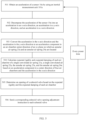
- FIG. 5 is a schematic flowchart of a vibration isolation control method of a vibration isolation apparatus 20a corresponding to the vibration isolation apparatus 20a and FIG. 4 according to some embodiments of this application.
- the procedure may be executed by an electronic control unit (Electronic Control Unit, ECU) 30.
- ECU Electronic Control Unit
- the procedure includes the following steps.
- An acceleration of a laser radar in this embodiment of this application is used to indicate a current vibration status of the laser radar.
- the acceleration may be decomposed in a vibration direction of the laser radar, to determine vibration reduction degrees of a first air spring 21a, a second air spring 22a, a third air spring 23a, and a third air spring 24a for the sensor 10a. Therefore, a coordinate system needs to be established for an air chamber.
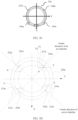
- four air chambers in the third air springs 23a and the third air springs 24a are distributed based on orthogonal coordinate system xy axes.
- the third air spring 23a is used as an example.
- a direction of a center line between a midpoint of a connection line between an intake valve 232a and an exhaust valve 233a and a circle center of the third air spring 23a is a positive direction of the x-axis, and a direction of an axis upward from a bottom to a top of the third air spring 23a is a positive direction of a z-axis (as shown in FIG. 6 below, and not shown in FIG. 3A to FIG. 3D ).
- a direction from a left side to a right side of the third air spring 23a is a positive direction of the y-axis, to establish an xyz spatial rectangular coordinate system, and is used for parameter calibration in actual use.
- the intake valve 232a is located in a first quadrant of the xy orthogonal coordinate system
- the exhaust valve 233a is located in a second quadrant of the orthogonal coordinate system.
- External vibrations conducted to the sensor 10a in different directions are decomposed along the xyz axes, so that the vibrations are converted to central directions of the four air chambers corresponding to the third air spring 23a to meet a lateral vibration isolation requirement.
- a part of the external vibration that is decomposed to the z-axis is converted to the first air spring 21a and the second air spring 22a, so that a vertical vibration isolation requirement is met.
- FIG. 6 is a schematic diagram of a principle in which the electronic control unit 30 decomposes the acceleration of the sensor 10a to components in directions of an x-axis, a y-axis, and a z-axis.
- the electronic control unit 30 obtains the acceleration a of the sensor 10a by using the inertial measurement unit 101a, where the acceleration a has a specific angle with the x-axis, the y-axis, and the z-axis.
- the vibration is transmitted to the sensor 10a, and a vibration state of the sensor 10a may be reflected by the acceleration of the sensor 10a. Therefore, after the vehicle 1 is started, the inertial measurement unit 101 may measure the acceleration of the sensor 10a, and send the acceleration to the electronic control unit 30. In this way, the electronic control unit 30 may determine, based on the acceleration of the sensor 10a, expected damping and expected rigidity of each air chamber in response to the vibration state, to reduce the vibration of the sensor 10a, reduce mechanical fatigue of the sensor 10a, reduce a structural fracture risk and a performance degradation speed of the sensor 10a, and prolong a service life of the sensor.
- the electronic control unit 30 Before the electronic control unit 30 performs this step, the electronic control unit 30 has controlled control valves 202 of air chambers in the first air spring 21a, the second air spring 22a, the third air spring 23a, and the third air spring 24a to supply a preset volume of air to the air chambers, so that internal pressures of the air chambers reach a preset value.
- the first air spring 21a, the second air spring 22a, the third air spring 23a, and the third air spring 24a filled with the preset volume of air can have a vibration isolation effect on the laser radar 10.
- the electronic control unit 30 decomposes the acceleration of the sensor 10a into an xy plane, and then decomposes force decomposed into the xy plane into the x-axis, to obtain an acceleration component ax1 of the acceleration a in the x-axis direction.
- the electronic control unit 30 decomposes the acceleration of the sensor 10a into an xz plane, then decomposes force decomposed into the xz plane into the x-axis, to obtain an acceleration component ax2 of the acceleration a in the x-axis direction, and finally adds ax1 and ax2 to obtain a total acceleration component ax on the x-axis.
- the electronic control unit 30 decomposes the acceleration of the sensor 10a into the y-axis, to obtain a total acceleration component ay of the acceleration a in the y-axis direction; and the electronic control unit 30 decomposes the acceleration of the sensor 10a into the z-axis, to obtain a total acceleration component az of the acceleration a in the z-axis direction.
- FIG. 7 is a schematic diagram of a principle of converting the acceleration in the x-axis direction and the acceleration in the y-axis direction to the acceleration component in the air chamber center direction of the xy plane on which the third air spring 23a is located according to some embodiments of this application. As shown in FIG.
- the electronic control unit 30 obtains, based on the acceleration ax in the x-axis direction, the acceleration component ay in the y-axis direction, and an included angle between an acceleration a1 and a center direction of an air chamber, components a131, a132, a133, and a134 in a central line direction of each air chamber of the third air spring 23a and the third air spring 24a.
- the expected rigidity of each air chamber is a capability of each air chamber in the first air spring 21a, the second air spring 22a, the third air spring 23a, and the third air spring 24a to resist elastic deformation when force is applied.
- the damping refers to a gradual decrease in vibration amplitude of any vibration system due to external actions or inherent reasons of the system. The damping helps reduce a resonance amplitude of a mechanical structure, to avoid mechanical damage caused by a vibration stress reaching a limit of the structure.
- the damping of each air chamber helps the sensor 10a quickly restore to a stable state after being subjected to an instantaneous impact, and vibration isolation and vibration reduction effects are high.
- the electronic control unit 30 calculates the expected damping and rigidity of each air chamber based on the acceleration component in the center direction of the four air chambers, the acceleration in the z-axis direction, and a preset collaborative control algorithm.
- the preset collaborative control algorithm may be a ceiling damping algorithm, a linear quadratic regulator (Linear Quadratic Regulator, LQR), or a model predictive control (Model Predictive Control, MPC) algorithm, but is not limited thereto.
- the expected rigidity and expected damping of each air chamber correspond to the expected barometric pressure of each air chamber.
- the expected barometric pressure of each air chamber and the fixed parameter of each air chamber may be converted into the expected rigidity and expected damping of each air chamber through theoretical calculation and experimental test calibration.
- the barometric pressure of each air chamber may be measured in real time by using a barometric pressure sensor. Therefore, the opening of the control valve 202 of each air chamber may be adjusted, so that the barometric pressure of each air chamber reaches the expected barometric pressure, and damping and rigidity of each air chamber reach an expected value.
- the electronic control unit 30 may search, based on the expected rigidity and the expected damping of each air chamber, a mapping table of the rigidity, the damping, the opening of the control valve, and the barometric pressure, for the opening of the control valve of each air chamber and the expected barometric pressure of each air chamber.
- step 506 Send a corresponding control valve opening adjustment instruction to each control valve, and then continue to perform step 501 at each preset time.
- the control valve opening adjustment instruction carries the opening of the control valve of each air chamber and expected barometric pressure information of each air chamber.
- the electronic control unit 30 controls the barometric pressure of each air chamber to reach the expected rigidity and damping, and reduces vertical (z-axis) and lateral (xy plane) vibration of the sensor 10a based on collaborative control based on closed-loop feedback.
- An embodiment of this application provides a computer-readable storage medium.
- the computer-readable storage medium stores instructions, and when the instructions are executed on an electronic device, the electronic device is enabled to perform the steps in the foregoing method embodiments.
- the disclosed embodiments may be implemented by hardware, firmware, software, or any combination thereof.
- the disclosed embodiments may be alternatively implemented as instructions carried by or stored on one or more temporary or non-temporary machine-readable (for example, computer-readable) storage media, and the instructions may be read and executed by one or more processors.
- the instructions may be distributed through a network or another computer-readable medium.
- the computer-readable medium may include any mechanism for storing or transmitting information in a computer (for example, a computer) readable form, including but not limited to a floppy disk, a compact disc, an optical disc, a read-only memory (CD-ROM), a magneto-optical disc, a read-only memory (Read-Only Memory, ROM), a random access memory (Random Access Memory, RAM), an erasable programmable read-only memory (Erasable Programmable Read-Only Memory, EPROM), an electrically erasable programmable read-only memory (Electrically Erasable Programmable Read-Only Memory, EEPROM), a magnetic card or an optical card, a flash memory, or a tangible computer-readable memory that transmits information (for example, a carrier wave, an infrared signal, a digital signal, or the like) through an internet through electrical, optical, acoustic, or other forms of transmission signals. Therefore, the computer-readable medium includes any type of computer-readable medium suitable
- FIG. 8 is a schematic diagram of a principle of adjusting a barometric pressure of an air chamber according to a control valve opening adjustment instruction according to some embodiments of this application.
- the air chamber in FIG. 8 may be any one of the first air spring 21a, the second air spring 22a, the third air spring 23a, and the third air spring 24a.
- the barometric pressure sensor 201a may measure a barometric pressure of an air chamber in real time.
- a comparator compares the barometric pressure measured in real time with an expected barometric pressure. If the barometric pressure is not equal to the expected barometric pressure, the electronic control unit 30 adjusts the opening of the control valve 202 based on the unequal comparison result and the determined opening of the control valve obtained in step 705, to adjust an air amount in the air chamber, so that the air chamber meets the expected barometric pressure as much as possible. In this way, the air chamber meets the expected damping and rigidity as much as possible.
- the electronic control unit 30 needs to periodically perform the control method of the vibration isolation apparatus 20a provided in this embodiment of this application, to slow down the vibration of the sensor 10a in real time, so as to improve an effect of slowing down the vibration of the sensor 10a.
- the air spring, the vibration isolation apparatus, or the sensor assembly may not only be applied to an unmanned mining vehicle in the field of large-scale unmanned driving engineering operation, but also may be applied to another vehicle.
- the vehicle in this application is a vehicle in a broad sense, and may be a vehicle (for example, a car, a truck, a motorcycle, a train, an airplane, or a ship), an industrial vehicle (for example, a forklift, a trailer, or a tractor), an engineering vehicle (for example, an excavator, a bulldozer, or a crane), an agricultural device (for example, a lawn mower or a harvester), a recreation device, or a toy vehicle.
- a type of the vehicle is not limited in this application.
- FIG. 9 is a top view of an unmanned mining vehicle according to some embodiments of this application.
- an unmanned mining vehicle 1 includes three groups of laser radars: a laser radar 10a, a laser radar 10b, and a laser radar 10c.
- the three groups of laser radars are respectively disposed at different positions on the unmanned mining vehicle 1.
- the laser radar 10a and the laser radar 10b are respectively disposed at two ends of a vehicle head of the unmanned mining vehicle 1, and the laser radar 10c is disposed at a rear of the unmanned mining vehicle 1.
- the three groups of laser radars are respectively configured to scan different areas.
- the laser radar 10a is configured to scan a sector area a at a left end of the vehicle head that uses the laser radar 10a as a circle center and whose preset radius is r1
- the laser radar 10b is configured to scan a sector area b at a right end of the vehicle head that uses the laser radar 10b as a circle center and whose preset radius is r2
- the laser radar 10c is configured to scan a sector area c at the rear of the vehicle that uses the laser radar 10c as a circle center and whose preset radius is r3.
- a type of the laser radar may be a mechanical laser radar or a solid-state laser radar, but is not limited thereto.
- FIG. 10 is a schematic diagram of a structure of a connection among a laser radar 10a, a vibration isolation apparatus 20a, and an unmanned mining vehicle 1 according to some embodiments of this application.
- the unmanned mining vehicle 1 includes a vehicle head 50, an iron frame 30, a support suspension beam 60, a laser radar 10a, and a vibration isolation apparatus 20a.
- the support suspension beam 60 is extended on the vehicle head of the unmanned mining vehicle 1
- the iron frame 30 is vertically disposed on the support suspension beam 60
- the iron frame 30 is fixedly connected to the support suspension beam 60.
- An upper surface of the vibration isolation apparatus 20a is fixedly connected to the iron frame 30, and a lower surface of the vibration isolation apparatus 20a is fixedly connected to the iron frame 30.
- the laser radar 10b and the vibration isolation apparatus 20b shown in FIG. 9 may alternatively be fixedly connected to the unmanned mining vehicle 1 by using the foregoing connection structure of the iron frame and the support suspension beam, and the laser radar 10c and the vibration isolation apparatus 20c may alternatively be fixedly connected to the unmanned mining vehicle 1 by using the foregoing connection structure of the iron frame and the support suspension beam. Details are not described herein again.
- the laser radar 10a is installed on the support suspension beam 60 of the unmanned mining vehicle 1.
- the support suspension beam 60 is also referred to as a suspension beam structural part.
- the suspension beam has an inherent vibration frequency, and when a road surface is not evenly and conducted to the suspension beam, a first-order bending vibration pattern exists in a vibration mode of the suspension beam. Based on different parameters such as a material, a cross section, an inertial moment, and a height, there may also be second-order and third-order bending vibration patterns, and the stability of the sensor is affected. Even with vertical steel plate reinforcement, it is difficult to ensure that it is not affected by the vibration of the suspension beam in some vibration directions and frequencies.
- the laser radar 10a uses the vibration isolation apparatus 20a provided in this embodiment of this application, when the unmanned mining vehicle 1 travels on an unstructured road and is vibrated, because the first air spring 21a, the second air spring 22a, the third air spring 23a, and the third air spring 24a have damping, the damping helps reduce an amplitude of a deviation from an initial position generated due to vibration after the laser radar 10a is vibrated, so that the laser radar 10a recovers to a stable state as quickly as possible.
- the vibration isolation apparatus 20a performs vibration isolation in a vertical direction (for example, a direction perpendicular to a road surface) on the laser radar 10a by using the damping feature of the first air spring 21a and the second air spring 22a on the laser radar 10a, and performs vibration isolation in a horizontal direction perpendicular to an axial direction on the laser radar 10a by using the damping feature of the third air spring 23a and the third air spring 24a on the laser radar 10a.
- a vertical direction for example, a direction perpendicular to a road surface
- the vibration of the laser radar 10a in a vertical direction (a y-axis direction) and a lateral direction (a non-y-axis direction) is reduced, mechanical fatigue of the laser radar 10a is reduced, a structural fracture risk and a performance degradation speed of the laser radar 10a are reduced, and a service life of the laser radar 10a is prolonged.
- the vibration isolation apparatus in embodiments of this application can effectively resolve a multi-dimensional vibration isolation problem of a sensor of a large engineering vehicle (for example, a mining vehicle) on a complex road surface such as a mine or a sensor on a suspension with poor performance, or prolong a life cycle of a precision sensor, to reduce costs.
- a large engineering vehicle for example, a mining vehicle
- a complex road surface such as a mine or a sensor on a suspension with poor performance
- prolong a life cycle of a precision sensor to reduce costs.
- the vibration isolation apparatus in embodiments of this application can reduce measurement precision of a vibration-sensitive sensor.
Landscapes
- Engineering & Computer Science (AREA)
- General Engineering & Computer Science (AREA)
- Mechanical Engineering (AREA)
- Physics & Mathematics (AREA)
- Acoustics & Sound (AREA)
- Aviation & Aerospace Engineering (AREA)
- Computer Networks & Wireless Communication (AREA)
- General Physics & Mathematics (AREA)
- Radar, Positioning & Navigation (AREA)
- Remote Sensing (AREA)
- Vibration Prevention Devices (AREA)
Abstract
Description
- This application relates to the vibration control field, and in particular, to an air spring, a vibration isolation apparatus, a sensor assembly, a vibration isolation control method, and a vehicle.
- Currently, sensors used to sense a surrounding environment in an unmanned driving process are usually disposed on a self-driving vehicle. In this way, the vehicle may automatically adjust a driving status of the vehicle based on sensor data obtained by the sensors. The sensors may be laser radars or the like.
- A large-scale unmanned engineering operation vehicle often travels on unstructured roads such as field roads, wading mud roads, and mining roads. A road surface of an unstructured road is not even, and the vehicle vibrates or even vibrates violently due to the uneven road surface. In addition, currently, most sensors are directly connected to a body or an external support suspension beam of the large-scale unmanned engineering operation vehicle. Therefore, the sensors on the vehicle also vibrate with vibration of the vehicle. In this way, long-time mechanical vibration causes problems such as mechanical fatigue, structural fracture, and performance degradation of the sensors. As a result, service lives of the sensors are shortened, and measurement precision of the sensors is reduced.
- For example, a traveling environment of an unmanned mining vehicle (such as a wide-body dump truck) in a mine is poor. The wide-body dump truck vibrates under external force. Sensors on the wide-body dump truck are directly connected to a steel plate of a body of the wide-body dump truck. A suspension system of the wide-body dump truck is a steel spring, with poor shock-absorbing performance. The sensors, especially built-in mechanical elements such as a laser radar and a millimeter-wave radar, and a micro-electro-mechanical system (Micro-Electro-Mechanical System, MEMS) element are likely affected by vibration. The sensors on the wide-body dump truck also vibrate with vibration of the wide-body dump truck, and detection precision of the sensors, especially the laser radar, is affected by the vibration. Long-time vibration may cause problems such as mechanical fatigue, structural fracture, and performance degradation of the sensors. As a result, service lives of the sensors are shortened, and replacement costs of the sensors are increased.
- Embodiments of this application provide an air spring, a vibration isolation apparatus, a sensor assembly, a vibration isolation control method, and a vehicle.
- According to a first aspect, an embodiment of this application provides an air spring, including an airway and at least two air chambers, where the at least two air chambers include a first air chamber and a second air chamber, the first air chamber and the second air chamber are distributed at an interval along the airway, the first air chamber is connected to the airway by using a first control valve, and the second air chamber is connected to the airway by using a second control valve.
- The air spring may be a third air spring in a specific embodiment, for example, a
third air spring 23a and athird air spring 24a. - According to the air spring in this embodiment of this application, when a target object such as a sensor is vibrated, the air spring can slow down lateral vibration of the target object such as the sensor, to reduce mechanical fatigue of the sensor, reduce a fracture risk and a performance degradation speed of the sensor assembly, prolong a service life of the sensor, reduce a quantity of replacement times, reduce replacement costs, and reduce impact of vibration on measurement precision of the sensor.
- In a possible implementation of the first aspect, the at least two air chambers further include a third air chamber and a fourth air chamber, where the first air chamber, the second air chamber, the third air chamber, and the fourth air chamber are evenly distributed along the airway, the third air chamber is connected to the airway by using a third control valve, and the fourth air chamber is connected to the airway by using a fourth control valve.
- In this embodiment of this application, the first air chamber, the second air chamber, the third air chamber, and the fourth air chamber are evenly distributed along the airway, to facilitate decomposition and calculation of a physical quantity in a vibration control process, effectively improve vibration control precision, and further improve calibration efficiency of the vibration isolation apparatus or the air spring.
- In a possible implementation of the first aspect, the airway is annular, and the first air chamber, the second air chamber, and the third air chamber are evenly distributed along a circumferential direction of the airway.
- In a possible implementation of the first aspect, the airway is further provided with an intake valve and an exhaust valve, and the intake valve and the exhaust valve are disposed on a same side of a circumferential diameter of the airway.
- The intake valve and the exhaust valve are disposed on the same side of the circumferential diameter of the airway, which helps reduce a volume of the apparatus and simplify and install intake and exhaust pipes.
- For example, an
intake valve 232a and anexhaust valve 233a are disposed on a same side of a diameter of thethird air spring 23a. In this way, to some extent, a connection distance between theintake valve 232a and an air supply apparatus and a connection distance between theexhaust valve 233a and the air supply apparatus may be shortened, a volume of the vibration isolation apparatus is reduced, and installation is convenient. - In a possible implementation of the first aspect, each of the at least two air chambers is provided with a barometric pressure sensor.
- The barometric pressure sensor is configured to measure a barometric pressure of each air chamber.
- In a possible implementation of the first aspect, the apparatus further includes a groove part, where the groove part is disposed on a perpendicular bisector between two adjacent air chambers in the at least two air chambers.
- Wiring harness of the sensor may pass through the groove part and disposed on the perpendicular bisector, to simplify a calibration parameter, improve calibration efficiency, simplify a vibration control calculation parameter, and improve vibration control precision.
- According to a second aspect, an embodiment of this application provides a vibration isolation apparatus, where the vibration isolation apparatus includes a first air spring and a second air spring, where the first air spring includes a first airway, a first air chamber, and a second air chamber, where the first air chamber and the second air chamber are distributed at an interval along the first airway; the first air chamber is connected to the first airway by using a first control valve, and the second air chamber is connected to the first airway by using a second control valve; and the second air spring is configured to attenuate a vibration component perpendicular to a plane on which the first air spring is located.
- The first air spring may be a third air spring in a specific embodiment, for example, a
third air spring 24a. - The second air spring may be a first air spring and a second air spring in a specific embodiment, for example, a
first air spring 21a and asecond air spring 22a. - In a possible implementation of the first aspect, the first air spring further includes a third air chamber and a fourth air chamber.
- The third air chamber is connected to the first airway by using a third control valve, and the fourth air chamber is connected to the first airway by using a fourth control valve; the first airway is annular, and the first air chamber, the second air chamber, the third air chamber, and the fourth air chamber are evenly distributed along a circumferential direction of the first airway; and the first air chamber, the second air chamber, the third air chamber, and the fourth air chamber are all provided with a barometric pressure sensor.
- In a possible implementation of the first aspect, the first airway is further provided with a first intake valve and a first exhaust valve, and the first intake valve and the first exhaust valve are disposed on a same side of a circumferential diameter of the first airway.
- In a possible implementation of the first aspect, the first air spring and the second air spring are of an integral structure; or the first air spring is fixedly connected to the second air spring.
- A manner of the fastened connection may include a detachable fastened connection and a non-detachable fastened connection. The detachable fastened connection may be a bolt connection, and the non-detachable fastened connection may be adhesive, but is not limited thereto.
- The integral structure can improve connection reliability, and reduce a volume and costs of a connection part. The detachable fastened connection may flexibly replace types of the first air spring, the second air spring, and the third air spring, and has better adaptability. For the non-detachable fastened connection, in a manufacturing stage before the vibration isolation apparatus is delivered from a factory, types of the first air spring, the second air spring, and the third air spring are determined.
- In a possible implementation of the first aspect, the apparatus further includes a third air spring, a fourth air spring, and a bracket, where the second spring, the first spring, the third spring, and the fourth spring are sequentially arranged, the second air spring is fixedly connected to the bracket, and the fourth air spring is fixedly connected to the bracket; the third air spring includes a second airway, a fifth air chamber, a sixth air chamber, a seventh air chamber, and an eighth air chamber, where the second airway is annular, the second airway is further provided with a second intake valve and a second exhaust valve, and the second intake valve and the second exhaust valve are disposed on a same side of a circumferential diameter of the second airway; the fifth air chamber, the sixth air chamber, the seventh air chamber, and the eighth air chamber are evenly distributed along a circumferential direction of the second airway, and the fifth air chamber, the sixth air chamber, the seventh air chamber, and the eighth air chamber are all provided with a barometric pressure sensor; and the fourth air spring is configured to attenuate a vibration component perpendicular to a plane on which the third air spring is located, and the third air spring is fixedly connected to the fourth air spring.
- In some implementations, the bracket may include a structure formed by an iron frame and a support suspension beam, but is not limited to the.
- The third air spring may be a third air spring in a specific embodiment, for example, a
third air spring 24a. - The fourth air spring may be a first air spring and a second air spring in a specific embodiment, for example, a
first air spring 21a and asecond air spring 22a. - In a possible implementation of the first aspect, the bracket is configured to fixedly connect the vibration isolation apparatus to a vehicle.
- In a possible implementation of the first aspect, both the second air spring and the fourth air spring are single convoluted air springs.
- According to a third aspect, an embodiment of this application provides a sensor assembly, including a vibration isolation apparatus and a sensor.
- The vibration isolation apparatus includes a first air spring and a second air spring, the first air spring is sleeved on a side surface of the sensor, the second air spring is disposed on a first end of the sensor, and the second air spring is configured to attenuate a vibration component perpendicular to a plane on which the first air spring is located; the first air spring includes a first airway, a first air chamber, a second air chamber, a third air chamber, and a fourth air chamber, where the first air chamber, the second air chamber, the third air chamber, and the fourth air chamber are evenly distributed along the airway; and the first air chamber is connected to the first airway by using a first control valve, the second air chamber is connected to the first airway by using a second control valve, the third air chamber is connected to the airway by using a third control valve, and the fourth air chamber is connected to the airway by using a fourth control valve.
- The first air spring may be a third air spring in a specific embodiment, for example, a
third air spring 24a. - The second air spring may be a first air spring and a second air spring in a specific embodiment, for example, a
first air spring 21a and asecond air spring 22a. - In a possible implementation of the first aspect, a third air spring and a fourth air spring are further included, where the second spring, the first spring, the third spring, and the fourth spring are sequentially arranged, the third air spring is sleeved on a side surface of the sensor, and the fourth air spring is disposed on a second end of the sensor; the third air spring includes a second airway, a fifth air chamber, a sixth air chamber, a seventh air chamber, and an eighth air chamber, where the second airway is annular, the second airway is further provided with a second intake valve and a second exhaust valve, and the second intake valve and the second exhaust valve are disposed on a same side of a circumferential diameter of the second airway; the fifth air chamber, the sixth air chamber, the seventh air chamber, and the eighth air chamber are evenly distributed along a circumferential direction of the second airway, and the fifth air chamber, the sixth air chamber, the seventh air chamber, and the eighth air chamber are all provided with a barometric pressure sensor; and the fourth air spring is configured to attenuate a vibration component perpendicular to a plane on which the third air spring is located, and the third air spring is fixedly connected to the fourth air spring.
- The third air spring may be a third air spring in a specific embodiment, for example, a
third air spring 24a. The fourth air spring may be a first air spring and a second air spring in a specific embodiment, for example, afirst air spring 21a and asecond air spring 22a. - According to a fourth aspect, an embodiment of this application provides a vibration isolation control method, where the method is applied to a vibration isolation control system, the vibration isolation control system includes an electronic control unit and an air spring, and the air spring includes an airway and at least two air chambers, where the at least two air chambers include a first air chamber and a second air chamber; the first air chamber and the second air chamber are distributed at an interval along the airway; and the first air chamber is connected to the airway by using a first control valve, and the second air chamber is connected to the airway by using a second control valve.
- The method includes:
- obtaining, by the electronic control unit, an acceleration of the sensor;
- decomposing, by the electronic control unit, the acceleration to a component in a preset direction, and determining, by the electronic control unit, expected rigidity and damping of the air chamber based on the component in the preset direction;
- determining an expected opening of each solenoid valve based on the expected rigidity and the damping; and
- sending a corresponding solenoid valve opening adjustment instruction to each solenoid valve based on the expected opening.
- According to a fourth aspect, an embodiment of this application provides a vehicle. An air spring is disposed on the vehicle, and the air spring is the air spring in any one of the possible implementations of the first aspect.
- According to a fifth aspect, an embodiment of this application provides a computer-readable storage medium. The computer-readable storage medium stores instructions, and when the instructions are executed on an electronic device, the electronic device is enabled to perform the vibration isolation control method in the possible implementations of the fourth aspect.
-
-
FIG. 1 is a schematic exploded diagram of a sensor assembly according to some embodiments of this application; -
FIG. 2A is a front view of an assembly state of a sensor assembly shown inFIG. 1 according to some embodiments of this application; -
FIG. 2B is a left view of an assembly state of a sensor assembly shown inFIG. 1 according to some embodiments of this application; -
FIG. 2C is a top view of an assembly state of a sensor assembly shown inFIG. 1 according to some embodiments of this application; -
FIG. 3A is a top view of athird air spring 23a inFIG. 1 ; -
FIG. 3B is a sectional view of athird air spring 23a in a direction A-A inFIG. 1 according to some embodiments of this application; -
FIG. 3C is a top view of athird air spring 24a inFIG. 1 ; -
FIG. 3D is a schematic diagram of a vibration reduction principle of athird air spring 24a inFIG. 3C ; -
FIG. 4 is a schematic diagram of a vibration isolation system according to some embodiments of this application; -
FIG. 5 is a schematic flowchart of a vibration isolation control method of avibration isolation apparatus 20a corresponding to thevibration isolation apparatus 20a andFIG. 4 according to some embodiments of this application; -
FIG. 6 is a schematic diagram of a principle in which anelectronic control unit 30 decomposes an acceleration of asensor 10a to components in directions of an x-axis, a y-axis, and a z-axis; -
FIG. 7 is a schematic diagram of a principle of converting an acceleration in an x-axis direction and an acceleration in a y-axis direction to an acceleration component in an air chamber center direction of an xy plane on which athird air spring 23a is located according to some embodiments of this application; -
FIG. 8 is a schematic diagram of a principle of adjusting a barometric pressure of an air chamber according to a control valve opening adjustment instruction according to some embodiments of this application; -
FIG. 9 is a top view of an unmanned mining vehicle according to some embodiments of this application; and -
FIG. 10 is a schematic diagram of a structure of a connection among alaser radar 10a, avibration isolation apparatus 20a, and anunmanned mining vehicle 1 according to some embodiments of this application. - 20a: vibration isolation apparatus; 21a: first air spring; 22a: second air spring; 23a: third air spring; 24a: third air spring; 211a: positioning hole; 212a: positioning hole; 213a: intake valve; 232a: intake valve; 102a: top protective cover; 103a: laser radar operating area; 104a: harness plug; 105a: bottom protective cover; 241a: connection part; 242a: opening; 243a: exhaust valve; 221a: positioning hole; 222a: positioning hole; 223a: intake valve; 214a: positioning hole; 234a: third air chamber; 235a: third air chamber; 236a: third air chamber; 237a: third air chamber; 238a: airway; 202a: control valve; 245a: third air chamber; 246a: third air chamber; 247a: third air chamber; 248a: third air chamber; 30: electronic control unit; 201a: barometric pressure sensor; 40: air supply apparatus; 10a: sensor; 101a: inertial measurement unit; 231a: connection part; 214a: exhaust valve; 1: unmanned mining vehicle; 50: vehicle head; 30: iron frame; 60: support suspension beam.
- The following describes implementations of this application by using specific embodiments. A person skilled in the art may easily learn of other advantages and effects of this application based on content disclosed in this specification.
- Although this application is described with reference to some embodiments, it does not mean that a characteristic of this application is limited only to this implementation. On the contrary, a purpose of describing this application with reference to an implementation is to cover another option or modification that may be derived based on claims of this application. To provide an in-depth understanding of this application, the following descriptions include a plurality of specific details. This application may be alternatively implemented without using these details. In addition, to avoid confusion or blurring a focus of this application, some specific details are omitted from the description. It should be noted that embodiments in this application and the features in embodiments may be mutually combined in the case of no conflict.
- It should be noted that, in descriptions of embodiments of this application, it should be noted that, unless otherwise specified and limited, terms "installation" and "connection" should be understood in a broad sense. For example, the "connection" may be a detachable connection, or may be a non-detachable connection, or may be a direct connection, or may be an indirect connection through an intermediary. It should be noted that, in this specification, reference numerals and letters in the following accompanying drawings represent similar items. Therefore, once an item is defined in an accompanying drawing, the item does not need to be further defined or interpreted in the following accompanying drawings. In descriptions of this application, it should be noted that orientation or location relationships indicated by terms "center", "above", "below", "left", "right", "vertical", "horizontal", "inner", "outer", and the like are orientation or location relationships based on the accompanying drawings, and are merely intended for conveniently describing this application and simplifying descriptions, rather than indicating or implying that an apparatus or an element in question needs to have a specific orientation or needs to be constructed and operated in a specific orientation, and therefore cannot be construed as a limitation on this application. In addition, terms "first" and "second" are merely used for a purpose of description, and shall not be understood as an indication or implication of relative importance.
- To resolve the technical problem in the background, an embodiment of this application provides a vibration isolation apparatus. The vibration isolation apparatus includes a first vibration isolation apparatus and a second vibration isolation apparatus. The first vibration isolation apparatus is configured to be disposed in a first direction of a target object, and the first vibration isolation apparatus is configured to slow down a vibration component of the target object in the first direction. The second vibration isolation apparatus is configured to be disposed in a second direction of the target object, and the second vibration isolation apparatus is configured to slow down a vibration component of the target object in the second direction.
- Based on the foregoing vibration isolation apparatus, when the target object is vibrated, the vibration isolation apparatus may simultaneously slow down the vibration in the first direction and the vibration in the second direction of the target object, to reduce mechanical fatigue of the target object, reduce a structural fracture risk and a performance degradation speed of the target object, and improve a service life of the target object.
- In some embodiments, the first vibration isolation apparatus may include a first air spring and a second air spring. The first air spring is configured to be disposed on a top and a bottom of the target object, and the first air spring is configured to slow down a vibration component in a direction from the top to the bottom of the target object. The second vibration isolation apparatus may include at least one third air spring, the at least one third air spring is disposed around a side surface of the target object, and the at least one third air spring is configured to slow down a lateral vibration component of the target object.
- The first air spring and a third air spring that is close to the first air spring may be an integral structure; or the first air spring may be fixedly connected to the third air spring that is close to the first air spring. A fastened connection manner may be bolt connection, or may be adhesive, but is not limited thereto.
- Similarly, the second air spring and a third air spring that is close to the second air spring may be an integral structure; or the second air spring may be fixedly connected to the third air spring that is close to the second air spring. A manner of the fastened connection may include a detachable fastened connection and a non-detachable fastened connection. The detachable fastened connection may be a bolt connection, and the non-detachable fastened connection may be adhesive, but is not limited thereto.
- The integral structure can improve connection reliability, and reduce a volume and costs of a connection part. The detachable fastened connection may flexibly replace types of the first air spring, the second air spring, and the third air spring, and has better adaptability. For the non-detachable fastened connection, in a manufacturing stage before the vibration isolation apparatus is delivered from a factory, types of the first air spring, the second air spring, and the third air spring are determined.
- Based on the foregoing vibration isolation apparatus, when a sensor is vibrated, the vibration isolation apparatus may slow down vibration from a top to a bottom of the sensor and lateral vibration, to reduce mechanical fatigue of the sensor, reduce a fracture risk and a performance degradation speed of a sensor assembly, prolong a service life of the sensor, reduce a quantity of replacement times, reduce replacement costs, and also reduce impact of vibration on measurement precision of the sensor.
- In some embodiments, the target object may be a sensor, for example, a laser radar. The first vibration isolation apparatus may include a first air spring and a second air spring. The first air spring is configured to be disposed on the top of the sensor, and the second air spring is configured to be disposed on the bottom of the sensor. The second vibration isolation apparatus may include at least one third air spring, and the at least one third air spring is disposed around a side surface of the sensor.
- In some embodiments, the first air spring may be a single convoluted air spring, a double convoluted air spring, or the like, but is not limited thereto; the second air spring may be a single convoluted air spring, a double convoluted air spring, or the like, but is not limited thereto; and the third air spring is an annular air spring. Each annular air spring is sleeved on the side surface of the sensor.
- In some other embodiments, the vibration isolation apparatus may be a plurality of air springs, and the plurality of air springs are disposed around the side surface of the sensor.
- The air spring refers to a spring that is filled with compressed air in a telescopic sealed container and uses air elasticity, commonly referred to as an airbag or the like.
- The following describes an example of a sensor assembly provided in embodiments of this application.
FIG. 1 is a schematic exploded diagram of a sensor assembly according to some embodiments of this application. As shown inFIG. 1 , the sensor assembly includes asensor 10a and avibration isolation apparatus 20a. Thesensor 10a may be a laser radar. A type of the laser radar may be a millimeter-wave radar, a solid-state laser radar, or the like. - The
vibration isolation apparatus 20a includes a first vibration isolation apparatus and a second vibration isolation apparatus. The first vibration isolation apparatus includes afirst air spring 21a and asecond air spring 22a. The second vibration isolation apparatus includes athird air spring 23a and athird air spring 24a. - The
first air spring 21a is disposed on a top of thesensor 10a, and thesecond air spring 22a is disposed on a bottom of thesensor 10a. Thethird air spring 23a and thethird air spring 24a are disposed around a side surface of thesensor 10a. - A bottom of the
first air spring 21a is fixedly connected to the top of thesensor 10a; a top of thesecond air spring 22a is fixedly connected to the bottom of thesensor 10a; a top of thethird air spring 23a is fixedly connected to the bottom of thefirst air spring 21a; and a bottom of thethird air spring 24a is fixedly connected to the top of thesecond air spring 22a. - A plurality of
positioning holes 211a are disposed on a top of thefirst air spring 21a, and thepositioning holes 211a are configured to fixedly connect thefirst air spring 21a to an external fastening structure. A plurality ofpositioning holes 221a are disposed at the top of thefirst air spring 21a, and thepositioning holes 221a are configured to fixedly connect thesecond air spring 22a to the external fastening structure. - The
third air spring 23a and thethird air spring 24a may be square or annular. - The following shows an example of a schematic assembly diagram of the sensor assembly in
FIG. 1 . For example,FIG. 2A is a front view of an assembly state of the sensor assembly shown inFIG. 1 according to some embodiments of this application. An assembly structure of thesensor 10a installed in thevibration isolation apparatus 20a may be shown inFIG. 2A . - In some embodiments, a
connection part 231a is disposed on a top that is of thethird air spring 23a and that is close to thefirst air spring 21a, a connection part is disposed on a bottom that is of thefirst air spring 21a and that is close to thethird air spring 23a, and theconnection part 231a of thethird air spring 23a is fixedly connected to the connection part of thefirst air spring 21a. - In some embodiments, a
connection part 241a is disposed on a top that is of thethird air spring 24a and that is close to thesecond air spring 22a, a connection part is disposed on a bottom that is of thesecond air spring 22a and that is close to thethird air spring 24a, and theconnection part 241a of thethird air spring 24a is fixedly connected to the connection part of thesecond air spring 22a. - In some embodiments, the connection part may be a screw hole, and the two connection parts are fixedly connected by using a bolt. In some other embodiments, the two connection parts may be fixedly connected through adhesive or integrated molding.
- In some embodiments, the
first air spring 21a may be a single convoluted air spring, thesecond air spring 22a may be a single convoluted air spring, thethird air spring 23a may be an annular air spring, and thethird air spring 24a may be an annular air spring. It may be understood that the single convoluted air spring is merely an example, and the single convoluted air spring may alternatively be replaced with another structure with a same function. This is not limited herein. Similarly, the annular air spring is merely an example, and the annular air spring may be replaced with another structure with a same function. This is not limited herein. - In some embodiments, the annular air spring may be disposed in a non-sensing area of the
sensor 10a, because the sensing area of thesensor 10a is configured to transmit and receive a signal, and if the sensing area is blocked, detection precision of thesensor 10a is affected. If the side surface of thesensor 10a includes a sensing area and two non-sensing areas, and a sensing area is disposed between one non-sensing area and the other non-sensing area, the two annular air springs are respectively disposed in one non-sensing area and the other non-sensing area. - For example, the
laser radar 10a includes a topprotective cover 102a, a laserradar operating area 103a, a bottomprotective cover 105a, and aharness plug 104a. Theharness plug 104a is disposed on the bottomprotective cover 105a. The laserradar operating area 103a is located between the topprotective cover 102a and the bottomprotective cover 105a. The laserradar operating area 103a is an optical path propagation area used to transmit and receive a laser, and obtains sensing data. Thethird air spring 24a is provided with agroove part 242a, and thegroove part 242a is disposed on a perpendicular bisector between two adjacent air chambers in the at least two air chambers. Theharness plug 104a may pass through thegroove part 242a. - Because the laser
radar operating area 103a is the optical path propagation area used to transmit and receive a laser, if another structure is disposed on the laserradar operating area 103a, precision of sensing data of the laserradar operating area 103a is affected. Because in some embodiments, thethird air spring 23a and thethird air spring 24a are sleeved on a part, other than the laserradar operating area 103a, on an outer side surface of thelaser radar 10a, and the laserradar operating area 103a used for optical path propagation is reserved. For example, thefirst air spring 21a is sleeved on an outer side wall in a circumferential direction of the topprotective cover 102a of thelaser radar 10a. Thesecond air spring 22a and thethird air spring 23a are sleeved on an outer side wall in a circumferential direction of the bottomprotective cover 105a of thelaser radar 10a. - The
sensor 10a may be a laser radar, or may be any other types of sensor. - In this embodiment of this application, the
first air spring 21a, thesecond air spring 22a, thethird air spring 23a, and thethird air spring 24a may partially wrap and fasten thelaser radar 10a, and do not block an optical path propagation path of thelaser radar 10a. In this way, the vibration isolation apparatus provided in this embodiment of this application not only can isolate vibration of thelaser radar 10a, but also cannot interfere with measurement of thelaser radar 10a in a vibration isolation process. This reduces mechanical fatigue of thelaser radar 10a, reduces a structural fracture risk and a performance degradation speed of thelaser radar 10a, prolongs a service life of the sensor, and reduces impact of vibration on measurement precision of thelaser radar 10a. - Structures of the
first air spring 21a, thesecond air spring 22a, thethird air spring 23a, and thethird air spring 24a, and connections and position relationships between thefirst air spring 21a, thesecond air spring 22a, thethird air spring 23a, and thethird air spring 24a and thesensor 10a may be changed based on structural features of thesensor 10a, to meet vibration isolation requirements of thefirst air spring 21a, thesecond air spring 22a, thethird air spring 23a, and thethird air spring 24a for thesensor 10a. - In some embodiments, the
sensor 10a is fixedly connected to the external fastening structure, thesensor 10a is disposed between thefirst air spring 21a and thesecond air spring 22a, and thefirst air spring 21a and thesecond air spring 22a clamp thesensor 10a. In this way, a center of gravity of thesensor 10a is effectively prevented from drifting and shaking, and additional vibration caused by an unstable center of gravity is effectively reduced. A fastened connection manner may be fastened connection by using a positioning hole. - For example,
FIG. 2B is a left view of the assembly state of the sensor assembly shown inFIG. 1 according to some embodiments of this application. - As shown in
FIG. 2B , a plurality ofpositioning holes 212a are evenly distributed along an axial direction of thefirst air spring 21a. In some embodiments, thepositioning holes 212a may be bolt holes. A plurality ofpositioning holes 222a are evenly distributed along an axial direction of thesecond air spring 22a. In some embodiments, thepositioning holes 222a may be bolt holes. - In some embodiments, the
first air spring 21a, thesecond air spring 22a, thethird air spring 23a, and thethird air spring 24a may be structures that can be filled with air. - Specifically, the structure that can be filled with air may be an air chamber that can be filled with air. For example, the
first air spring 21a includes a first air chamber that can be filled with air; thesecond air spring 22a includes a second air chamber that can be filled with air; thethird air spring 23a includes a plurality of third air chambers that are isolated from each other in a circumferential direction; and thethird air spring 24a includes a plurality of third air chambers that are isolated from each other in a circumferential direction. The first air chamber, the second air chamber, and the third air chamber are filled with air, and when the sensor is vibrated, the first air chamber, the second air chamber, and the third air chamber can generate damping on the vibration, to slow down the vibration of thesensor 10a. - The
first air spring 21a may be provided with an air supply structure configured to supply air to the first air chamber. For example,FIG. 2C is a top view of the assembly state of the sensor assembly shown inFIG. 1 according to some embodiments of this application. As shown inFIG. 2C , anintake valve 213a and anexhaust valve 214a are disposed on the top of thefirst air spring 21a, and theintake valve 213a is configured to connect to the air supply apparatus, and pass air into the first air chamber of thefirst air spring 21a. An air supply structure in thesecond air spring 22a is the same as the air supply structure in thefirst air spring 21a, and details are not described herein. - In some embodiments of this application, the intake valve and the exhaust valve are disposed on a same side of a circumferential diameter of an airway. In this way, to some extent, a connection distance between the intake valve and the air supply apparatus and a connection distance between the exhaust valve and the air supply apparatus may be shortened, a volume of the vibration isolation apparatus is reduced, and installation is convenient.
- Each time the
sensor 10a vibrates, a vibration direction in a radial direction may be different. Therefore, to facilitate decomposition and calculation of a physical quantity in a vibration control process, for example, to reduce each vibration more precisely and/or more conveniently decompose and calculate an acceleration. A plurality of independent, evenly distributed, and variable vibration isolation structures may be disposed in a circumferential direction of thethird air spring 23a. In some embodiments, the vibration isolation structure is an air chamber. Specifically, thethird air spring 23a includes a plurality of third air chambers that are isolated from each other and evenly distributed in a circumferential direction. In this way, precision of vibration control can be effectively improved, and calibration efficiency of the vibration isolation apparatus or the air spring can be further improved. - For example,
FIG. 3A is a top view of thethird air spring 23a inFIG. 1 . As shown inFIG. 3A , four third air chambers are disposed at even intervals in a circumferential direction of thethird air spring 23a: athird air chamber 234a, athird air chamber 235a, athird air chamber 236a, and athird air chamber 237a. - The
third air chamber 234a, thethird air chamber 235a, thethird air chamber 236a, and thethird air chamber 237a may be in various shapes. For example,FIG. 3B is a sectional view of thethird air spring 23a in a direction A-A inFIG. 1 according to some embodiments of this application. As shown inFIG. 3B , thethird air chamber 234a, thethird air chamber 235a, thethird air chamber 236a, and thethird air chamber 237a have a same structure, and are all sealed chambers surrounded by a part of an inner wall of thethird air spring 23a and an arc surface. The part of the inner wall of thethird air spring 23a that forms thethird air chamber 234a, thethird air chamber 235a, thethird air chamber 236a, and thethird air chamber 237a is A, and an area of the area A is less than a preset area, so that mutual force between thethird air chamber 234a, thethird air chamber 235a, thethird air chamber 236a, and thethird air chamber 237a and thesensor 10a are more concentrated, a vibration reduction response effect of thesensor 10a is improved. - Similarly, a structure of the air chamber in the
third air spring 24a is the same as that of the air chamber in thethird air spring 23a. For example,FIG. 3C is a top view of thethird air spring 24a inFIG. 1 . As shown inFIG. 3C , four third air chambers are disposed at even intervals in a circumferential direction of thethird air spring 24a, and the four third air chambers are vibration isolation structures: athird air chamber 245a, athird air chamber 246a, athird air chamber 247a, and athird air chamber 248a. - To slow down vibration of the
sensor 10a when thesensor 10a is vibrated, barometric pressure values in thethird air chamber 234a, thethird air chamber 235a, thethird air chamber 236a, and thethird air chamber 237a need to be changed. Therefore, as shown inFIG. 3B , anairway 238a may be disposed in the circumferential direction of thethird air spring 23a, and anintake valve 232a and anexhaust valve 233a are disposed on an outer side surface of theairway 238a. Theintake valve 232a is configured to connect to the air supply apparatus, so that the air supply apparatus may inject air into theairway 238a by using theintake valve 232a. - The
intake valve 232a and theexhaust valve 233a are disposed on a same side of a diameter of thethird air spring 23a. In this way, to some extent, a connection distance between theintake valve 232a and an air supply apparatus and a connection distance between theexhaust valve 233a and the air supply apparatus may be shortened, a volume of the vibration isolation apparatus is reduced, and installation is convenient. -
Control valves 202 are disposed between thethird air chamber 234a, thethird air chamber 235a, thethird air chamber 236a, and thethird air chamber 237a and theairway 238a, and acontrol valve 202 of a corresponding air chamber is opened, so that air in theairway 238a flows into the corresponding air chamber. Similarly, thethird air spring 24a may also include a plurality of third air chambers that are isolated from each other in a circumferential direction, and the first air chamber, the second air chamber, and the third air chamber are filled with air. - The airway in this embodiment of this application is a pipe for air supply and exhaust, and may be an annular structure.
- The control valve in this embodiment of this application may include a control valve, and further include another structure that can be used to control a switch. When the control valve is open, the air in the airway can be controlled to enter the air chamber. When the control valve is closed, the air in the airway can be prevented from entering the air chamber.
- In some embodiments, the
intake valve 232a and theexhaust valve 233a are disposed on the same side of the diameter of thethird air spring 23a. In this way, to some extent, a connection distance between theintake valve 232a and an air supply apparatus and a connection distance between theexhaust valve 233a and the air supply apparatus may be shortened, a volume of the vibration isolation apparatus is reduced, and installation is convenient. - A shape of each third air chamber may be a spherical shape, for example, a flat sphere.
- The air supply apparatus includes an air tank, an air pump, and an air path, where the air tank is connected to the air pump through the air path, and the air pump is connected to an intake valve in each vibration isolation apparatus through the air path. The air tank is an air supply source of the foregoing air chambers. The air pump provides power for the air tank and the air path through air supply.
- Structures of the third air chamber, the control valve, the intake valve, the exhaust valve, and the airway in the
third air spring 24a are the same as structures of the third air chamber, the control valve, the intake valve, the exhaust valve, and the airway in thesecond air spring 22a, and details are not described herein again. - To slow down vibration of the
sensor 10a, damping and rigidity of the air spring are adjustable. In this way, when thesensor 10a is vibrated and acts on the air spring, the air spring generates, based on the adjusted damping and rigidity, force opposite to force used to cushion thesensor 10a towards the air spring, to slow down vibration of thesensor 10a. In addition, a larger value of an acceleration representing the vibration of thesensor 10a indicates larger damping and rigidity of the air spring that are adjusted; and on the contrary, a smaller value of an acceleration representing the vibration of thesensor 10a indicates smaller damping and rigidity of the air spring that are adjusted. The air spring may be any one or more of thefirst air spring 21a, thesecond air spring 22a, thethird air spring 23a, and thethird air spring 24a. - For example,
FIG. 3D is a schematic diagram of a vibration reduction principle of thethird air spring 24a inFIG. 3C . As shown inFIG. 3D , to slow down the vibration of thesensor 10a, the damping and rigidity of thethird air spring 24a are adjustable. In this way, when thesensor 10a is vibrated and acts on thethird air spring 24a, thethird air spring 24a generates, based on the adjusted damping and rigidity, force F2 opposite to force F1 used to cushion thesensor 10a towards thethird air spring 24a, to slow down the vibration of thesensor 10a. In addition, a larger value of the acceleration representing the vibration of thesensor 10a indicates larger damping and rigidity of thethird air spring 24a that are adjusted; and on the contrary, a smaller value of the acceleration representing the vibration of thesensor 10a indicates smaller damping and rigidity of thethird air spring 24a that are adjusted. -
FIG. 4 is a schematic diagram of a vibration isolation system according to some embodiments of this application. As shown inFIG. 4 , the vibration isolation system includes anelectronic control unit 30, avibration isolation apparatus 20a, asensor 10a, and an air supply apparatus 40. - The
vibration isolation apparatus 20a includes abarometric pressure sensor 201a and acontrol valve 202a. Thebarometric pressure sensor 201a is configured to measure a barometric pressure of each air chamber in thevibration isolation apparatus 20a. Thecontrol valve 202a is configured to adjust a volume of air entering each air chamber in thevibration isolation apparatus 20a. - An inertial measurement unit (Inertial Measurement Unit, IMU) 101a is built in the
sensor 10a, and theinertial measurement unit 101a is configured to measure an acceleration when thesensor 10a vibrates. In some other embodiments, theinertial measurement unit 101a is disposed on a surface of thesensor 10a. - The
control valve 202a is connected to the air supply apparatus 40. Thebarometric pressure sensor 201a, thecontrol valve 202a, and thesensor 10a are separately connected to theelectronic control unit 30. Theelectronic control unit 30 is configured to receive an acceleration that is sent by the inertial measurement unit 101b and that is generated when alaser radar 10b vibrates. Theelectronic control unit 30 determines, based on the acceleration, expected damping and expected rigidity of each air chamber. Theelectronic control unit 30 then determines an opening of the control valve based on the expected rigidity and expected damping of each air chamber, and sends a corresponding control valve opening adjustment instruction to each control valve. Theelectronic control unit 30 cyclically performs the foregoing steps in a next cycle, to reduce vibration of thesensor 10a in real time. -
FIG. 5 is a schematic flowchart of a vibration isolation control method of avibration isolation apparatus 20a corresponding to thevibration isolation apparatus 20a andFIG. 4 according to some embodiments of this application. The procedure may be executed by an electronic control unit (Electronic Control Unit, ECU) 30. - As shown in
FIG. 5 , the procedure includes the following steps. - 501: Obtain an acceleration of a
sensor 10a by using aninertial measurement unit 101a. - An acceleration of a laser radar in this embodiment of this application is used to indicate a current vibration status of the laser radar. In this embodiment of this application, the acceleration may be decomposed in a vibration direction of the laser radar, to determine vibration reduction degrees of a
first air spring 21a, asecond air spring 22a, athird air spring 23a, and athird air spring 24a for thesensor 10a. Therefore, a coordinate system needs to be established for an air chamber. - For example, as shown in
FIG. 3A to FIG. 3D , four air chambers in the third air springs 23a and the third air springs 24a are distributed based on orthogonal coordinate system xy axes. - The
third air spring 23a is used as an example. A direction of a center line between a midpoint of a connection line between anintake valve 232a and anexhaust valve 233a and a circle center of thethird air spring 23a is a positive direction of the x-axis, and a direction of an axis upward from a bottom to a top of thethird air spring 23a is a positive direction of a z-axis (as shown inFIG. 6 below, and not shown inFIG. 3A to FIG. 3D ). A direction from a left side to a right side of thethird air spring 23a is a positive direction of the y-axis, to establish an xyz spatial rectangular coordinate system, and is used for parameter calibration in actual use. Correspondingly, theintake valve 232a is located in a first quadrant of the xy orthogonal coordinate system, and theexhaust valve 233a is located in a second quadrant of the orthogonal coordinate system. - External vibrations conducted to the
sensor 10a in different directions are decomposed along the xyz axes, so that the vibrations are converted to central directions of the four air chambers corresponding to thethird air spring 23a to meet a lateral vibration isolation requirement. A part of the external vibration that is decomposed to the z-axis is converted to thefirst air spring 21a and thesecond air spring 22a, so that a vertical vibration isolation requirement is met. - For example,
FIG. 6 is a schematic diagram of a principle in which theelectronic control unit 30 decomposes the acceleration of thesensor 10a to components in directions of an x-axis, a y-axis, and a z-axis. As shown inFIG. 6 , theelectronic control unit 30 obtains the acceleration a of thesensor 10a by using theinertial measurement unit 101a, where the acceleration a has a specific angle with the x-axis, the y-axis, and the z-axis. - After a
vehicle 1 is vibrated, the vibration is transmitted to thesensor 10a, and a vibration state of thesensor 10a may be reflected by the acceleration of thesensor 10a. Therefore, after thevehicle 1 is started, the inertial measurement unit 101 may measure the acceleration of thesensor 10a, and send the acceleration to theelectronic control unit 30. In this way, theelectronic control unit 30 may determine, based on the acceleration of thesensor 10a, expected damping and expected rigidity of each air chamber in response to the vibration state, to reduce the vibration of thesensor 10a, reduce mechanical fatigue of thesensor 10a, reduce a structural fracture risk and a performance degradation speed of thesensor 10a, and prolong a service life of the sensor. - Before the
electronic control unit 30 performs this step, theelectronic control unit 30 has controlledcontrol valves 202 of air chambers in thefirst air spring 21a, thesecond air spring 22a, thethird air spring 23a, and thethird air spring 24a to supply a preset volume of air to the air chambers, so that internal pressures of the air chambers reach a preset value. In this way, when thevehicle 1 is vibrated and the vibration is transmitted to thesensor 10a, thefirst air spring 21a, thesecond air spring 22a, thethird air spring 23a, and thethird air spring 24a filled with the preset volume of air can have a vibration isolation effect on the laser radar 10. - 502: Decompose the acceleration of the
sensor 10a into an acceleration in an x-axis direction, an acceleration in a y-axis direction, and an acceleration in a z-axis direction. - For example, as shown in
FIG. 6 , theelectronic control unit 30 decomposes the acceleration of thesensor 10a into an xy plane, and then decomposes force decomposed into the xy plane into the x-axis, to obtain an acceleration component ax1 of the acceleration a in the x-axis direction. Similarly, theelectronic control unit 30 decomposes the acceleration of thesensor 10a into an xz plane, then decomposes force decomposed into the xz plane into the x-axis, to obtain an acceleration component ax2 of the acceleration a in the x-axis direction, and finally adds ax1 and ax2 to obtain a total acceleration component ax on the x-axis. By analogy, theelectronic control unit 30 decomposes the acceleration of thesensor 10a into the y-axis, to obtain a total acceleration component ay of the acceleration a in the y-axis direction; and theelectronic control unit 30 decomposes the acceleration of thesensor 10a into the z-axis, to obtain a total acceleration component az of the acceleration a in the z-axis direction. - 503: Convert the acceleration in the x-axis direction and the acceleration in the y-axis direction to an acceleration component in an air chamber center direction of an xy plane on which the
third air spring 23a and thethird air spring 24a are located. - For example, according to some embodiments of this application,
FIG. 7 is a schematic diagram of a principle of converting the acceleration in the x-axis direction and the acceleration in the y-axis direction to the acceleration component in the air chamber center direction of the xy plane on which thethird air spring 23a is located according to some embodiments of this application. As shown inFIG. 7 , theelectronic control unit 30 obtains, based on the acceleration ax in the x-axis direction, the acceleration component ay in the y-axis direction, and an included angle between an acceleration a1 and a center direction of an air chamber, components a131, a132, a133, and a134 in a central line direction of each air chamber of thethird air spring 23a and thethird air spring 24a. - 504: Calculate expected rigidity and expected damping of each air chamber of the
first air spring 21a, thesecond air spring 22a, thethird air spring 23a, and thethird air spring 24a based on an acceleration component in a center direction of four air chambers and the acceleration in the z-axis direction. - As shown in
FIG. 7 , the four air chambers are evenly distributed along a circumferential direction. In this way, it is more convenient to decompose the acceleration to the x-axis and the y-axis, and perform acceleration decomposition calculation. - In this embodiment of this application, the expected rigidity of each air chamber is a capability of each air chamber in the
first air spring 21a, thesecond air spring 22a, thethird air spring 23a, and thethird air spring 24a to resist elastic deformation when force is applied. The damping refers to a gradual decrease in vibration amplitude of any vibration system due to external actions or inherent reasons of the system. The damping helps reduce a resonance amplitude of a mechanical structure, to avoid mechanical damage caused by a vibration stress reaching a limit of the structure. In this embodiment of this application, the damping of each air chamber helps thesensor 10a quickly restore to a stable state after being subjected to an instantaneous impact, and vibration isolation and vibration reduction effects are high. - In some embodiments, the
electronic control unit 30 calculates the expected damping and rigidity of each air chamber based on the acceleration component in the center direction of the four air chambers, the acceleration in the z-axis direction, and a preset collaborative control algorithm. The preset collaborative control algorithm may be a ceiling damping algorithm, a linear quadratic regulator (Linear Quadratic Regulator, LQR), or a model predictive control (Model Predictive Control, MPC) algorithm, but is not limited thereto. - 505: Determine, based on the expected rigidity and the expected damping of each air chamber, an expected barometric pressure of each air chamber and an expected opening of a corresponding control valve.
- Based on features of the air spring, the expected rigidity and expected damping of each air chamber correspond to the expected barometric pressure of each air chamber. To be specific, based on the expected barometric pressure of each air chamber and a fixed parameter of each air chamber, the expected barometric pressure of each air chamber and the fixed parameter of each air chamber may be converted into the expected rigidity and expected damping of each air chamber through theoretical calculation and experimental test calibration. In addition, the barometric pressure of each air chamber may be measured in real time by using a barometric pressure sensor. Therefore, the opening of the
control valve 202 of each air chamber may be adjusted, so that the barometric pressure of each air chamber reaches the expected barometric pressure, and damping and rigidity of each air chamber reach an expected value. - The
electronic control unit 30 may search, based on the expected rigidity and the expected damping of each air chamber, a mapping table of the rigidity, the damping, the opening of the control valve, and the barometric pressure, for the opening of the control valve of each air chamber and the expected barometric pressure of each air chamber. - 506: Send a corresponding control valve opening adjustment instruction to each control valve, and then continue to perform step 501 at each preset time.
- The control valve opening adjustment instruction carries the opening of the control valve of each air chamber and expected barometric pressure information of each air chamber. The
electronic control unit 30 controls the barometric pressure of each air chamber to reach the expected rigidity and damping, and reduces vertical (z-axis) and lateral (xy plane) vibration of thesensor 10a based on collaborative control based on closed-loop feedback. - An embodiment of this application provides a computer-readable storage medium. The computer-readable storage medium stores instructions, and when the instructions are executed on an electronic device, the electronic device is enabled to perform the steps in the foregoing method embodiments.
- In some cases, the disclosed embodiments may be implemented by hardware, firmware, software, or any combination thereof. The disclosed embodiments may be alternatively implemented as instructions carried by or stored on one or more temporary or non-temporary machine-readable (for example, computer-readable) storage media, and the instructions may be read and executed by one or more processors. For example, the instructions may be distributed through a network or another computer-readable medium. Therefore, the computer-readable medium may include any mechanism for storing or transmitting information in a computer (for example, a computer) readable form, including but not limited to a floppy disk, a compact disc, an optical disc, a read-only memory (CD-ROM), a magneto-optical disc, a read-only memory (Read-Only Memory, ROM), a random access memory (Random Access Memory, RAM), an erasable programmable read-only memory (Erasable Programmable Read-Only Memory, EPROM), an electrically erasable programmable read-only memory (Electrically Erasable Programmable Read-Only Memory, EEPROM), a magnetic card or an optical card, a flash memory, or a tangible computer-readable memory that transmits information (for example, a carrier wave, an infrared signal, a digital signal, or the like) through an internet through electrical, optical, acoustic, or other forms of transmission signals. Therefore, the computer-readable medium includes any type of computer-readable medium suitable for storing or transmitting electronic instructions or information in a computer-readable form (for example, a computer).
-
FIG. 8 is a schematic diagram of a principle of adjusting a barometric pressure of an air chamber according to a control valve opening adjustment instruction according to some embodiments of this application. - The air chamber in
FIG. 8 may be any one of thefirst air spring 21a, thesecond air spring 22a, thethird air spring 23a, and thethird air spring 24a. - As shown in
FIG. 8 , thebarometric pressure sensor 201a may measure a barometric pressure of an air chamber in real time. A comparator compares the barometric pressure measured in real time with an expected barometric pressure. If the barometric pressure is not equal to the expected barometric pressure, theelectronic control unit 30 adjusts the opening of thecontrol valve 202 based on the unequal comparison result and the determined opening of the control valve obtained in step 705, to adjust an air amount in the air chamber, so that the air chamber meets the expected barometric pressure as much as possible. In this way, the air chamber meets the expected damping and rigidity as much as possible. - If the
vehicle 1 is always in a traveling state, because flatness of the mining road is different, a vibration degree of thevehicle 1 changes, and the acceleration of thesensor 10a also changes accordingly. Therefore, theelectronic control unit 30 needs to periodically perform the control method of thevibration isolation apparatus 20a provided in this embodiment of this application, to slow down the vibration of thesensor 10a in real time, so as to improve an effect of slowing down the vibration of thesensor 10a. - The air spring, the vibration isolation apparatus, or the sensor assembly may not only be applied to an unmanned mining vehicle in the field of large-scale unmanned driving engineering operation, but also may be applied to another vehicle.
- The vehicle in this application is a vehicle in a broad sense, and may be a vehicle (for example, a car, a truck, a motorcycle, a train, an airplane, or a ship), an industrial vehicle (for example, a forklift, a trailer, or a tractor), an engineering vehicle (for example, an excavator, a bulldozer, or a crane), an agricultural device (for example, a lawn mower or a harvester), a recreation device, or a toy vehicle. A type of the vehicle is not limited in this application.
- The following describes the technical solutions of this application by using an example in which a sensor assembly is applied to an unmanned mining vehicle and a sensor is a laser radar.
-
FIG. 9 is a top view of an unmanned mining vehicle according to some embodiments of this application. - As shown in
FIG. 9 , anunmanned mining vehicle 1 includes three groups of laser radars: alaser radar 10a, alaser radar 10b, and alaser radar 10c. The three groups of laser radars are respectively disposed at different positions on theunmanned mining vehicle 1. For example, thelaser radar 10a and thelaser radar 10b are respectively disposed at two ends of a vehicle head of theunmanned mining vehicle 1, and thelaser radar 10c is disposed at a rear of theunmanned mining vehicle 1. - The three groups of laser radars are respectively configured to scan different areas. For example, the
laser radar 10a is configured to scan a sector area a at a left end of the vehicle head that uses thelaser radar 10a as a circle center and whose preset radius is r1, thelaser radar 10b is configured to scan a sector area b at a right end of the vehicle head that uses thelaser radar 10b as a circle center and whose preset radius is r2, and thelaser radar 10c is configured to scan a sector area c at the rear of the vehicle that uses thelaser radar 10c as a circle center and whose preset radius is r3. - A type of the laser radar may be a mechanical laser radar or a solid-state laser radar, but is not limited thereto.
-
FIG. 10 is a schematic diagram of a structure of a connection among alaser radar 10a, avibration isolation apparatus 20a, and anunmanned mining vehicle 1 according to some embodiments of this application. - As shown in
FIG. 10 , theunmanned mining vehicle 1 includes avehicle head 50, aniron frame 30, asupport suspension beam 60, alaser radar 10a, and avibration isolation apparatus 20a. Thesupport suspension beam 60 is extended on the vehicle head of theunmanned mining vehicle 1, theiron frame 30 is vertically disposed on thesupport suspension beam 60, and theiron frame 30 is fixedly connected to thesupport suspension beam 60. An upper surface of thevibration isolation apparatus 20a is fixedly connected to theiron frame 30, and a lower surface of thevibration isolation apparatus 20a is fixedly connected to theiron frame 30. - The
laser radar 10b and the vibration isolation apparatus 20b shown inFIG. 9 may alternatively be fixedly connected to theunmanned mining vehicle 1 by using the foregoing connection structure of the iron frame and the support suspension beam, and thelaser radar 10c and the vibration isolation apparatus 20c may alternatively be fixedly connected to theunmanned mining vehicle 1 by using the foregoing connection structure of the iron frame and the support suspension beam. Details are not described herein again. - The
laser radar 10a is installed on thesupport suspension beam 60 of theunmanned mining vehicle 1. Thesupport suspension beam 60 is also referred to as a suspension beam structural part. Generally, the suspension beam has an inherent vibration frequency, and when a road surface is not evenly and conducted to the suspension beam, a first-order bending vibration pattern exists in a vibration mode of the suspension beam. Based on different parameters such as a material, a cross section, an inertial moment, and a height, there may also be second-order and third-order bending vibration patterns, and the stability of the sensor is affected. Even with vertical steel plate reinforcement, it is difficult to ensure that it is not affected by the vibration of the suspension beam in some vibration directions and frequencies. - However, because the
laser radar 10a uses thevibration isolation apparatus 20a provided in this embodiment of this application, when theunmanned mining vehicle 1 travels on an unstructured road and is vibrated, because thefirst air spring 21a, thesecond air spring 22a, thethird air spring 23a, and thethird air spring 24a have damping, the damping helps reduce an amplitude of a deviation from an initial position generated due to vibration after thelaser radar 10a is vibrated, so that thelaser radar 10a recovers to a stable state as quickly as possible. Thevibration isolation apparatus 20a performs vibration isolation in a vertical direction (for example, a direction perpendicular to a road surface) on thelaser radar 10a by using the damping feature of thefirst air spring 21a and thesecond air spring 22a on thelaser radar 10a, and performs vibration isolation in a horizontal direction perpendicular to an axial direction on thelaser radar 10a by using the damping feature of thethird air spring 23a and thethird air spring 24a on thelaser radar 10a. In this way, to some extent, the vibration of thelaser radar 10a in a vertical direction (a y-axis direction) and a lateral direction (a non-y-axis direction) is reduced, mechanical fatigue of thelaser radar 10a is reduced, a structural fracture risk and a performance degradation speed of thelaser radar 10a are reduced, and a service life of thelaser radar 10a is prolonged. - In conclusion, embodiments of this application have at least the following beneficial effects:
- To some extent, the vibration isolation apparatus in embodiments of this application can effectively resolve a multi-dimensional vibration isolation problem of a sensor of a large engineering vehicle (for example, a mining vehicle) on a complex road surface such as a mine or a sensor on a suspension with poor performance, or prolong a life cycle of a precision sensor, to reduce costs.
- To some extent, the vibration isolation apparatus in embodiments of this application can reduce measurement precision of a vibration-sensitive sensor.
- Reference to "an embodiment", "some embodiments", or the like described in this specification indicates that one or more embodiments of this application include a specific feature, structure, or characteristic described with reference to embodiments. Therefore, statements such as "in an embodiment", "in some embodiments", "in some other embodiments", and "in other embodiments" that appear at different places in this specification do not necessarily mean reference to a same embodiment, instead, they mean "one or more but not all of embodiments", unless otherwise specifically emphasized. The terms "include", "comprise", "have", and their variants all mean "include but are not limited to", unless otherwise specifically emphasized.
- The foregoing descriptions are merely specific embodiments of this application, but are not intended to limit the protection scope of this application. Any variation or replacement readily figured out by a person skilled in the art within the technical scope disclosed in this application shall fall within the protection scope of this application. In a case that no conflict occurs, embodiments of this application and features in embodiments may be mutually combined. Therefore, the protection scope of this application shall be subject to the protection scope of the claims.
Claims (18)
- An air spring, comprising an airway and at least two air chambers, whereinthe at least two air chambers comprise a first air chamber and a second air chamber;the first air chamber and the second air chamber are distributed at an interval along the airway; andthe first air chamber is connected to the airway by using a first control valve, and the second air chamber is connected to the airway by using a second control valve.
- The air spring according to claim 1, wherein the at least two air chambers further comprise a third air chamber and a fourth air chamber, whereinthe first air chamber, the second air chamber, the third air chamber, and the fourth air chamber are evenly distributed along the airway; andthe third air chamber is connected to the airway by using a third control valve, and the fourth air chamber is connected to the airway by using a fourth control valve.
- The air spring according to claim 2, wherein the airway is annular, and the first air chamber, the second air chamber, and the third air chamber are evenly distributed along a circumferential direction of the airway.
- The air spring according to claim 3, wherein the airway is further provided with an intake valve and an exhaust valve, and the intake valve and the exhaust valve are disposed on a same side of a circumferential diameter of the airway.
- The air spring according to any one of claims 1 to 4, wherein each of the at least two air chambers is provided with a barometric pressure sensor.
- The air spring according to any one of claims 1 to 5, further comprising a groove part, wherein the groove part is disposed on a perpendicular bisector between two adjacent air chambers in the at least two air chambers.
- A vibration isolation apparatus, comprising a first air spring and a second air spring, whereinthe first air spring comprises a first airway, a first air chamber, and a second air chamber, wherein the first air chamber and the second air chamber are distributed at an interval along the first airway;the first air chamber is connected to the first airway by using a first control valve, and the second air chamber is connected to the first airway by using a second control valve; andthe second air spring is configured to attenuate a vibration component perpendicular to a plane on which the first air spring is located.
- The apparatus according to claim 7, wherein the first air spring further comprises a third air chamber and a fourth air chamber, whereinthe third air chamber is connected to the first airway by using a third control valve, and the fourth air chamber is connected to the first airway by using a fourth control valve;the first airway is annular, and the first air chamber, the second air chamber, the third air chamber, and the fourth air chamber are evenly distributed along a circumferential direction of the first airway; andthe first air chamber, the second air chamber, the third air chamber, and the fourth air chamber are all provided with a barometric pressure sensor.
- The apparatus according to claim 8, wherein the first airway is further provided with a first intake valve and a first exhaust valve, and the first intake valve and the first exhaust valve are disposed on a same side of a circumferential diameter of the first airway.
- The apparatus according to any one of claims 7 to 9, wherein the first air spring and the second air spring are of an integral structure; or the first air spring is fixedly connected to the second air spring.
- The apparatus according to any one of claims 7 to 10, further comprising a third air spring, a fourth air spring, and a bracket, wherein the second spring, the first spring, the third spring, and the fourth spring are sequentially arranged, the second air spring is fixedly connected to the bracket, and the fourth air spring is fixedly connected to the bracket;the third air spring comprises a second airway, a fifth air chamber, a sixth air chamber, a seventh air chamber, and an eighth air chamber, wherein the second airway is annular, the second airway is further provided with a second intake valve and a second exhaust valve, and the second intake valve and the second exhaust valve are disposed on a same side of a circumferential diameter of the second airway;the fifth air chamber, the sixth air chamber, the seventh air chamber, and the eighth air chamber are evenly distributed along a circumferential direction of the second airway, and the fifth air chamber, the sixth air chamber, the seventh air chamber, and the eighth air chamber are all provided with a barometric pressure sensor; andthe fourth air spring is configured to attenuate a vibration component perpendicular to a plane on which the third air spring is located, and the third air spring is fixedly connected to the fourth air spring.
- The apparatus according to claim 11, wherein the bracket is configured to fixedly connect the vibration isolation apparatus to a vehicle.
- The apparatus according to any one of claims 7 to 12, wherein both the second air spring and the fourth air spring are single convoluted air springs.
- A sensor assembly, comprising a vibration isolation apparatus and a sensor, whereinthe vibration isolation apparatus comprises a first air spring and a second air spring, the first air spring is sleeved on a side surface of the sensor, the second air spring is disposed on a first end of the sensor, and the second air spring is configured to attenuate a vibration component perpendicular to a plane on which the first air spring is located;the first air spring comprises a first airway, a first air chamber, a second air chamber, a third air chamber, and a fourth air chamber, wherein the first air chamber, the second air chamber, the third air chamber, and the fourth air chamber are evenly distributed along the airway; andthe first air chamber is connected to the first airway by using a first control valve, the second air chamber is connected to the first airway by using a second control valve, the third air chamber is connected to the airway by using a third control valve, and the fourth air chamber is connected to the airway by using a fourth control valve.
- The sensor assembly according to claim 14, further comprising a third air spring and a fourth air spring, wherein the second spring, the first spring, the third spring, and the fourth spring are sequentially arranged, the third air spring is sleeved on a side surface of the sensor, and the fourth air spring is disposed on a second end of the sensor;the third air spring comprises a second airway, a fifth air chamber, a sixth air chamber, a seventh air chamber, and an eighth air chamber, wherein the second airway is annular, the second airway is further provided with a second intake valve and a second exhaust valve, and the second intake valve and the second exhaust valve are disposed on a same side of a circumferential diameter of the second airway;the fifth air chamber, the sixth air chamber, the seventh air chamber, and the eighth air chamber are evenly distributed along a circumferential direction of the second airway, and the fifth air chamber, the sixth air chamber, the seventh air chamber, and the eighth air chamber are all provided with a barometric pressure sensor; andthe fourth air spring is configured to attenuate a vibration component perpendicular to a plane on which the third air spring is located, and the third air spring is fixedly connected to the fourth air spring.
- A vibration isolation control method, wherein the method is applied to a vibration isolation control system, the vibration isolation control system comprises an electronic control unit and an air spring, and the air spring comprises an airway and at least two air chambers, whereinthe at least two air chambers comprise a first air chamber and a second air chamber;the first air chamber and the second air chamber are distributed at an interval along the airway; andthe first air chamber is connected to the airway by using a first control valve, and the second air chamber is connected to the airway by using a second control valve; andthe method comprises:obtaining, by the electronic control unit, an acceleration of the sensor;decomposing, by the electronic control unit, the acceleration to a component in a preset direction, and determining, by the electronic control unit, expected rigidity and damping of the air chamber based on the component in the preset direction;determining an expected opening of each solenoid valve based on the expected rigidity and the damping; andsending a corresponding solenoid valve opening adjustment instruction to each solenoid valve based on the expected opening.
- A vehicle, wherein an air spring is disposed on the vehicle, and the air spring is the air spring according to any one of claims 1 to 6.
- A computer-readable storage medium, wherein the computer-readable storage medium stores instructions, and when the instructions are executed on an electronic device, the electronic device is enabled to perform the vibration isolation control method according to claim 16.
Applications Claiming Priority (1)
| Application Number | Priority Date | Filing Date | Title |
|---|---|---|---|
| PCT/CN2022/077074 WO2023155188A1 (en) | 2022-02-21 | 2022-02-21 | Air spring, vibration isolation device, sensor assembly, vibration isolation control method, and vehicle |
Publications (2)
| Publication Number | Publication Date |
|---|---|
| EP4467838A1 true EP4467838A1 (en) | 2024-11-27 |
| EP4467838A4 EP4467838A4 (en) | 2025-10-08 |
Family
ID=87577248
Family Applications (1)
| Application Number | Title | Priority Date | Filing Date |
|---|---|---|---|
| EP22926515.2A Pending EP4467838A4 (en) | 2022-02-21 | 2022-02-21 | AIR SPRING, VIBRATION ISOLATION DEVICE, SENSOR ARRANGEMENT, VIBRATION ISOLATION CONTROL METHOD AND VEHICLE |
Country Status (4)
| Country | Link |
|---|---|
| US (1) | US20240410437A1 (en) |
| EP (1) | EP4467838A4 (en) |
| CN (1) | CN117222824B (en) |
| WO (1) | WO2023155188A1 (en) |
Families Citing this family (1)
| Publication number | Priority date | Publication date | Assignee | Title |
|---|---|---|---|---|
| WO2025107031A1 (en) * | 2023-11-23 | 2025-05-30 | A.C.N. 166 970 627 Pty Ltd | Monitoring system for vibration dampening device |
Family Cites Families (11)
| Publication number | Priority date | Publication date | Assignee | Title |
|---|---|---|---|---|
| JPH11294520A (en) * | 1998-04-08 | 1999-10-29 | Canon Inc | Vibration removing apparatus, exposure apparatus and device manufacturing method using the same, and vibration removing method |
| US6698730B2 (en) * | 2001-10-04 | 2004-03-02 | Bfs Diversified Products, Llc | Dual rate air spring |
| US7114710B2 (en) * | 2004-09-03 | 2006-10-03 | Bilz Schwingungstechnix Gmbh | Pneumatic vibration isolator |
| JP2006151161A (en) * | 2004-11-29 | 2006-06-15 | Kayaba Ind Co Ltd | Air spring and suspension |
| CN102278408B (en) * | 2011-05-05 | 2013-04-17 | 江苏大学 | Coaxial integrated air spring absorber with linkage and controllable rigidity and damping |
| CN102678808A (en) * | 2012-06-12 | 2012-09-19 | 南京农业大学 | Shock absorbing system with combined rigidity and damping adjusting function and shock absorbing method |
| CN108266486A (en) * | 2017-12-18 | 2018-07-10 | 宁波中倚机电科技发展有限公司 | Volume has the adjustable air spring additional air chamber of grade |
| CN208074076U (en) * | 2018-04-16 | 2018-11-09 | 山东交通技师学院 | A kind of band auxiliary chamber stiffness-adjustable air spring assembly |
| CN110873143A (en) * | 2018-08-29 | 2020-03-10 | 郑州宇通客车股份有限公司 | Variable-stiffness air spring system, vehicle and vehicle stability control method |
| CN111810581B (en) * | 2020-05-27 | 2021-05-07 | 厦门大学 | A Large-scale Precision Vibration Isolation Platform Based on Air Springs |
| CN111853415A (en) * | 2020-08-17 | 2020-10-30 | 武汉第二船舶设计研究所(中国船舶重工集团公司第七一九研究所) | Pipe support hanger |
-
2022
- 2022-02-21 EP EP22926515.2A patent/EP4467838A4/en active Pending
- 2022-02-21 CN CN202280004151.7A patent/CN117222824B/en active Active
- 2022-02-21 WO PCT/CN2022/077074 patent/WO2023155188A1/en not_active Ceased
-
2024
- 2024-08-20 US US18/810,234 patent/US20240410437A1/en active Pending
Also Published As
| Publication number | Publication date |
|---|---|
| US20240410437A1 (en) | 2024-12-12 |
| CN117222824A (en) | 2023-12-12 |
| EP4467838A4 (en) | 2025-10-08 |
| WO2023155188A1 (en) | 2023-08-24 |
| CN117222824B (en) | 2026-03-24 |
Similar Documents
| Publication | Publication Date | Title |
|---|---|---|
| US6834736B2 (en) | Active vehicle suspension with a hydraulic spring | |
| AU2020314717B2 (en) | Gas spring sensors using millimeter wavelength radar and gas spring assemblies and suspension systems including same | |
| EP0290181B1 (en) | Vehicle engine suspension systems | |
| US20240410437A1 (en) | Air spring, vibration isolation apparatus, sensor assembly, vibration isolation control method, and vehicle | |
| US20110049774A1 (en) | Shock absorber having compressible fluid | |
| CN101398052A (en) | Heavy load precision damper and vibration reduction system formed thereby | |
| EP1028887A1 (en) | Coordinated control of an active suspension system | |
| EP3436293B1 (en) | Internal gas spring displacement sensors as well as gas spring assemblies and suspension systems including same | |
| EP1028886A1 (en) | Active suspension system for a work vehicle | |
| US20110272229A1 (en) | Vehicle-mounted active vibration reducing device | |
| US6523816B1 (en) | Method of damping vibration, active hydraulic anti-vibration mount and vehicle including such a mount | |
| CN105952836A (en) | Impact resistance minitype inertial measurement unit with adjustable damping | |
| Foumani et al. | Optimization of engine mount characteristics using experimental/numerical analysis | |
| CA2674461C (en) | Reflector and gas spring assembly | |
| CN207814316U (en) | A kind of omnidirectional's shock-damping structure of suspension type MEMS inertial navigation products | |
| CN115010058A (en) | Aerial work platform with leveling function and its attitude adjustment method | |
| JP6634122B1 (en) | Gas spring type anti-vibration device | |
| JP3856676B2 (en) | Active vibration isolation method | |
| KR101288628B1 (en) | Road-arm type dynamic characteristic tester, test method thereof dynamic characteristic testing system | |
| US8812191B2 (en) | Control device for an adjustable chassis system | |
| TW202340623A (en) | Vibration isolator | |
| Rahmfeld et al. | Active vibration damping for off-road vehicles using valveless linear actuators | |
| CN107218341B (en) | Double-layer active control vibration damping device and method | |
| HK1135359B (en) | Reflector and gas spring assembly | |
| JP2004028184A (en) | Bracket for mounting vibration isolator and vibration isolator provided with this bracket |
Legal Events
| Date | Code | Title | Description |
|---|---|---|---|
| STAA | Information on the status of an ep patent application or granted ep patent |
Free format text: STATUS: THE INTERNATIONAL PUBLICATION HAS BEEN MADE |
|
| PUAI | Public reference made under article 153(3) epc to a published international application that has entered the european phase |
Free format text: ORIGINAL CODE: 0009012 |
|
| STAA | Information on the status of an ep patent application or granted ep patent |
Free format text: STATUS: REQUEST FOR EXAMINATION WAS MADE |
|
| 17P | Request for examination filed |
Effective date: 20240822 |
|
| AK | Designated contracting states |
Kind code of ref document: A1 Designated state(s): AL AT BE BG CH CY CZ DE DK EE ES FI FR GB GR HR HU IE IS IT LI LT LU LV MC MK MT NL NO PL PT RO RS SE SI SK SM TR |
|
| RAP1 | Party data changed (applicant data changed or rights of an application transferred) |
Owner name: SHENZHEN YINWANG INTELLIGENTTECHNOLOGIES CO., LTD. |
|
| DAV | Request for validation of the european patent (deleted) | ||
| DAX | Request for extension of the european patent (deleted) | ||
| REG | Reference to a national code |
Ref country code: DE Ref legal event code: R079 Free format text: PREVIOUS MAIN CLASS: F16F0009500000 Ipc: F16F0009040000 |
|
| A4 | Supplementary search report drawn up and despatched |
Effective date: 20250908 |
|
| RIC1 | Information provided on ipc code assigned before grant |
Ipc: F16F 9/04 20060101AFI20250902BHEP Ipc: F16F 15/027 20060101ALI20250902BHEP Ipc: F16F 15/023 20060101ALI20250902BHEP Ipc: G01S 7/02 20060101ALI20250902BHEP Ipc: G01S 13/931 20200101ALN20250902BHEP Ipc: B60R 19/48 20060101ALN20250902BHEP |