EP4467830A1 - Bearing arrangement for a wind turbine and wind turbine - Google Patents
Bearing arrangement for a wind turbine and wind turbine Download PDFInfo
- Publication number
- EP4467830A1 EP4467830A1 EP23174816.1A EP23174816A EP4467830A1 EP 4467830 A1 EP4467830 A1 EP 4467830A1 EP 23174816 A EP23174816 A EP 23174816A EP 4467830 A1 EP4467830 A1 EP 4467830A1
- Authority
- EP
- European Patent Office
- Prior art keywords
- chamber
- bearing
- bearing arrangement
- opening
- lubricant
- Prior art date
- Legal status (The legal status is an assumption and is not a legal conclusion. Google has not performed a legal analysis and makes no representation as to the accuracy of the status listed.)
- Granted
Links
Images




Classifications
-
- F—MECHANICAL ENGINEERING; LIGHTING; HEATING; WEAPONS; BLASTING
- F16—ENGINEERING ELEMENTS AND UNITS; GENERAL MEASURES FOR PRODUCING AND MAINTAINING EFFECTIVE FUNCTIONING OF MACHINES OR INSTALLATIONS; THERMAL INSULATION IN GENERAL
- F16C—SHAFTS; FLEXIBLE SHAFTS; ELEMENTS OR CRANKSHAFT MECHANISMS; ROTARY BODIES OTHER THAN GEARING ELEMENTS; BEARINGS
- F16C23/00—Bearings for exclusively rotary movement adjustable for aligning or positioning
- F16C23/06—Ball or roller bearings
- F16C23/08—Ball or roller bearings self-adjusting
- F16C23/082—Ball or roller bearings self-adjusting by means of at least one substantially spherical surface
- F16C23/086—Ball or roller bearings self-adjusting by means of at least one substantially spherical surface forming a track for rolling elements
-
- F—MECHANICAL ENGINEERING; LIGHTING; HEATING; WEAPONS; BLASTING
- F03—MACHINES OR ENGINES FOR LIQUIDS; WIND, SPRING, OR WEIGHT MOTORS; PRODUCING MECHANICAL POWER OR A REACTIVE PROPULSIVE THRUST, NOT OTHERWISE PROVIDED FOR
- F03D—WIND MOTORS
- F03D80/00—Details, components or accessories not provided for in groups F03D1/00 - F03D17/00
- F03D80/70—Bearing or lubricating arrangements
- F03D80/705—Lubrication circuits; Lubrication delivery means
- F03D80/709—Bearing lubrication
-
- F—MECHANICAL ENGINEERING; LIGHTING; HEATING; WEAPONS; BLASTING
- F03—MACHINES OR ENGINES FOR LIQUIDS; WIND, SPRING, OR WEIGHT MOTORS; PRODUCING MECHANICAL POWER OR A REACTIVE PROPULSIVE THRUST, NOT OTHERWISE PROVIDED FOR
- F03D—WIND MOTORS
- F03D80/00—Details, components or accessories not provided for in groups F03D1/00 - F03D17/00
- F03D80/80—Arrangement of components within nacelles or towers
- F03D80/88—Arrangement of components within nacelles or towers of mechanical components
- F03D80/881—Arrangement of components within nacelles or towers of mechanical components within nacelles
-
- F—MECHANICAL ENGINEERING; LIGHTING; HEATING; WEAPONS; BLASTING
- F16—ENGINEERING ELEMENTS AND UNITS; GENERAL MEASURES FOR PRODUCING AND MAINTAINING EFFECTIVE FUNCTIONING OF MACHINES OR INSTALLATIONS; THERMAL INSULATION IN GENERAL
- F16C—SHAFTS; FLEXIBLE SHAFTS; ELEMENTS OR CRANKSHAFT MECHANISMS; ROTARY BODIES OTHER THAN GEARING ELEMENTS; BEARINGS
- F16C19/00—Bearings with rolling contact, for exclusively rotary movement
- F16C19/52—Bearings with rolling contact, for exclusively rotary movement with devices affected by abnormal or undesired conditions
- F16C19/525—Bearings with rolling contact, for exclusively rotary movement with devices affected by abnormal or undesired conditions related to temperature and heat, e.g. insulation
-
- F—MECHANICAL ENGINEERING; LIGHTING; HEATING; WEAPONS; BLASTING
- F16—ENGINEERING ELEMENTS AND UNITS; GENERAL MEASURES FOR PRODUCING AND MAINTAINING EFFECTIVE FUNCTIONING OF MACHINES OR INSTALLATIONS; THERMAL INSULATION IN GENERAL
- F16C—SHAFTS; FLEXIBLE SHAFTS; ELEMENTS OR CRANKSHAFT MECHANISMS; ROTARY BODIES OTHER THAN GEARING ELEMENTS; BEARINGS
- F16C33/00—Parts of bearings; Special methods for making bearings or parts thereof
- F16C33/30—Parts of ball or roller bearings
- F16C33/66—Special parts or details in view of lubrication
- F16C33/6603—Special parts or details in view of lubrication with grease as lubricant
- F16C33/6622—Details of supply and/or removal of the grease, e.g. purging grease
- F16C33/6625—Controlling or conditioning the grease supply
-
- F—MECHANICAL ENGINEERING; LIGHTING; HEATING; WEAPONS; BLASTING
- F16—ENGINEERING ELEMENTS AND UNITS; GENERAL MEASURES FOR PRODUCING AND MAINTAINING EFFECTIVE FUNCTIONING OF MACHINES OR INSTALLATIONS; THERMAL INSULATION IN GENERAL
- F16C—SHAFTS; FLEXIBLE SHAFTS; ELEMENTS OR CRANKSHAFT MECHANISMS; ROTARY BODIES OTHER THAN GEARING ELEMENTS; BEARINGS
- F16C33/00—Parts of bearings; Special methods for making bearings or parts thereof
- F16C33/30—Parts of ball or roller bearings
- F16C33/66—Special parts or details in view of lubrication
- F16C33/6637—Special parts or details in view of lubrication with liquid lubricant
- F16C33/6685—Details of collecting or draining, e.g. returning the liquid to a sump
-
- F—MECHANICAL ENGINEERING; LIGHTING; HEATING; WEAPONS; BLASTING
- F05—INDEXING SCHEMES RELATING TO ENGINES OR PUMPS IN VARIOUS SUBCLASSES OF CLASSES F01-F04
- F05B—INDEXING SCHEME RELATING TO WIND, SPRING, WEIGHT, INERTIA OR LIKE MOTORS, TO MACHINES OR ENGINES FOR LIQUIDS COVERED BY SUBCLASSES F03B, F03D AND F03G
- F05B2240/00—Components
- F05B2240/50—Bearings
-
- F—MECHANICAL ENGINEERING; LIGHTING; HEATING; WEAPONS; BLASTING
- F05—INDEXING SCHEMES RELATING TO ENGINES OR PUMPS IN VARIOUS SUBCLASSES OF CLASSES F01-F04
- F05B—INDEXING SCHEME RELATING TO WIND, SPRING, WEIGHT, INERTIA OR LIKE MOTORS, TO MACHINES OR ENGINES FOR LIQUIDS COVERED BY SUBCLASSES F03B, F03D AND F03G
- F05B2260/00—Function
- F05B2260/98—Lubrication
-
- F—MECHANICAL ENGINEERING; LIGHTING; HEATING; WEAPONS; BLASTING
- F16—ENGINEERING ELEMENTS AND UNITS; GENERAL MEASURES FOR PRODUCING AND MAINTAINING EFFECTIVE FUNCTIONING OF MACHINES OR INSTALLATIONS; THERMAL INSULATION IN GENERAL
- F16C—SHAFTS; FLEXIBLE SHAFTS; ELEMENTS OR CRANKSHAFT MECHANISMS; ROTARY BODIES OTHER THAN GEARING ELEMENTS; BEARINGS
- F16C2233/00—Monitoring condition, e.g. temperature, load, vibration
-
- F—MECHANICAL ENGINEERING; LIGHTING; HEATING; WEAPONS; BLASTING
- F16—ENGINEERING ELEMENTS AND UNITS; GENERAL MEASURES FOR PRODUCING AND MAINTAINING EFFECTIVE FUNCTIONING OF MACHINES OR INSTALLATIONS; THERMAL INSULATION IN GENERAL
- F16C—SHAFTS; FLEXIBLE SHAFTS; ELEMENTS OR CRANKSHAFT MECHANISMS; ROTARY BODIES OTHER THAN GEARING ELEMENTS; BEARINGS
- F16C2360/00—Engines or pumps
- F16C2360/31—Wind motors
-
- Y—GENERAL TAGGING OF NEW TECHNOLOGICAL DEVELOPMENTS; GENERAL TAGGING OF CROSS-SECTIONAL TECHNOLOGIES SPANNING OVER SEVERAL SECTIONS OF THE IPC; TECHNICAL SUBJECTS COVERED BY FORMER USPC CROSS-REFERENCE ART COLLECTIONS [XRACs] AND DIGESTS
- Y02—TECHNOLOGIES OR APPLICATIONS FOR MITIGATION OR ADAPTATION AGAINST CLIMATE CHANGE
- Y02E—REDUCTION OF GREENHOUSE GAS [GHG] EMISSIONS, RELATED TO ENERGY GENERATION, TRANSMISSION OR DISTRIBUTION
- Y02E10/00—Energy generation through renewable energy sources
- Y02E10/70—Wind energy
- Y02E10/72—Wind turbines with rotation axis in wind direction
Definitions
- the disclosure relates to a bearing arrangement for a wind turbine, in particular to a rotor bearing arrangement.
- the disclosure further relates to a wind turbine, in particular to a wind turbine which comprises a bearing arrangement as described herein.
- a wind turbine may include a rotor that includes a rotatable rotor assembly having multiple rotor blades.
- the rotor blades transform wind energy into a drive torque that drives the generator via a drive train.
- Embodiments of the disclosure provide a bearing arrangement for a wind turbine.
- the bearing arrangement comprises a bearing.
- the bearing arrangement comprises a bearing housing.
- the bearing housing houses an interior space in which the bearing is arranged.
- the bearing housing comprises an opening configured to drain lubricant from the interior space.
- the bearing arrangement comprises a chamber.
- the chamber comprises a fluidic connection with the opening.
- a damping space is formed inside the chamber.
- the damping space is arranged inside the chamber.
- the damping space is defined by the chamber.
- the damping space is arranged inside the chamber to throttle a lubricant flow out of the interior space.
- the bearing arrangement is a rotor bearing arrangement of a wind turbine.
- the rotor bearing arrangement comprising the chamber to throttle a lubricant flow out of the interior space may correspond to both the rotor side bearing and the gearbox side bearing.
- the bearing arrangement and in particular the bearing is, for example, lubricated with grease or another lubricant, like an oil. It is important to contain a desired amount of lubricant inside the bearing housing in the interior space. Insufficient amount of lubricant in the bearing leads to higher wear and premature failure. On the other hand, high splashing losses lead to temperature raise and therefore reduced base viscosity which leads to lower film thickness, and eventually, to premature failure.
- the chamber with the damping space of the disclosure acts like a choke or a throttle to dampen the outflow of the lubricant.
- the lubricant as it flows through the chamber, loses its momentum and/or energy.
- the lubricant settles down and forms a kind of a barrier for lubricant coming out of the interior space.
- the lubricant in particular, is not flowing like a Newtoninan fluid, but rather like a structural viscous or even plastic fluid. This means, for example, that the lubricant is able to stay in a certain form and position without flowing away until a sufficient impulse or momentum occurs that triggers the movement.
- the chamber allows an outflow of lubricant in a controlled manner, wherein an undesirably high outflow of lubricant can be avoided.
- the amount of lubricant inside the bearing can be reliably kept within given thresholds.
- the choice of shape and dimensions of the chamber may depend on the capacity of the bearing housing, such that the impulses generated in the lubricant by the rotating bearing may be minimized to desired extents based on operational characteristics.
- the chamber is arranged at least partly outside of the bearing housing.
- the chamber is arranged at least partly inside the bearing housing. It is possible to arrange the chamber at a free space of the bearing housing depending on the design of the bearing housing and the bearing arrangement. Thus, available space can be used efficiently.
- the chamber comprises an inlet opening and an outlet opening.
- the inlet opening is connectable to the opening.
- Lubricant which flows out of the interior space can be reliably transferred to the chamber via the inlet opening.
- Lubricant which exits the chamber can be reliably guided to a collection container via the outlet opening.
- a cross-section of the inlet opening of the chamber is different from a cross-section of the damping space. It is possible that the cross-section of the inlet opening is smaller than the cross-section of the damping space. Alternatively, the cross-section of the inlet opening is larger than the cross-section of the damping space.
- the chamber comprises a first tube. The first tube is connectable to one of the inlet opening and the outlet opening. The other of the inlet opening and the outlet opening is in fluid communication with the damping space. The first tube comprises a cross-section that is different from the cross-section of the damping space.
- the chamber can be designed like a siphon.
- the bearing arrangement comprises a hose.
- the hose is fluidically connectable between the chamber and the opening. This allows freedom for the arrangement of the chamber relative to the opening and the bearing housing.
- the bearing arrangement comprises an outlet hose.
- the outlet hose is fluidically connectable to the chamber at a first end.
- the outlet hose comprises a second end for releasing the lubricant into the collection container. This allows an arrangement of the outlet opening at a distance from the collection container.
- At least one aperture is defined in the bearing housing.
- the opening is in fluid communication with the chamber through the at least one aperture.
- the aperture is a hole in the bearing housing.
- the chamber comprises a vent.
- the chamber can be vented in a controlled manner by the use of the vent.
- the bearing arrangement comprises a thermal control module for regulating a chamber temperature.
- the thermal control module comprises an insulation for insulating the chamber such that the interior of the chamber can be kept warmer than the outside.
- the thermal control module comprises a heater for heating the chamber.
- the thermal control module comprises a cooler for cooling the chamber.
- the thermal control module allows control of the temperature of the chamber depending on external environmental conditions in order to maintain at least one of a desired density, viscosity and other properties of the lubricant.
- the bearing arrangement comprises a damper.
- the damper is arranged inside the chamber.
- the damper comprises at least one of a baffle, an orifice plate, a mesh, a gap, a deflector plate, and a guide vane.
- a desired damping effect and throttle of the lubricant flow can be realized with the damper.
- the damper for example, is selected dependent on environmental conditions at the installation side of the wind turbine and/or the type of lubricant used.
- the damper comprises a plurality of dampers which are arranged inside the chamber.
- the dampers can be of the same type or of different types.
- the dampers can have different shapes or the same shape.
- the dampers can be arranged in parallel, in series and/or inclined relative to one another.
- the dampers can be arranged in a staggered, eclipsed and/or inclined manner.
- the damper comprises a spring that is biased towards the opening.
- the spring provides a resisting force acting against the lubricant flow out of the interior space.
- the pressure and momentum of the lubricant can be controlled by the spring.
- the damper comprises a baffle or a plurality of baffles that can be moved to control a resisting force against the lubricant flow.
- the baffle is connected to the spring and pivotable around a pin joint.
- the baffles are moved such that a gap for the lubricant flow is smaller or even closed to stop the lubricant flow.
- control of the lubricant flow is possible by adjusting the degree of deflection of the buffer.
- wind turbine wherein the wind turbine comprises a nacelle.
- the wind turbine comprises a bearing arrangement according to one of the described embodiments.
- the bearing arrangement is arranged within the nacelle.
- a wind turbine 100 comprises a tower 102.
- the tower 102 is connected to a foundation 104 fixed on a ground.
- the foundation 104 is formed in and supported by the ground.
- a nacelle 106 is arranged on a top end of the tower 102 opposite to the foundation 104.
- the nacelle 106 houses the drive train, among other components and subassemblies.
- a generator is arranged which is connected via the drive train to a rotor 108.
- the drive train comprises, for example, a gearbox and a rotor shaft 105 ( Figure 3 ).
- the rotor 108 comprises several rotor blades 110.
- the rotor blades 110 are mounted on a rotor hub 112.
- the rotor hub 112 is connected to the rotor shaft 105.
- the rotor 108 is driven in operation by an airflow, for example wind.
- the rotational movement of the rotor 108 is transmitted via the drive train to the generator.
- the generator converts the mechanical output of the rotor 108 into electrical energy.
- the wind turbine 100 comprises a bearing arrangement 200.
- the bearing arrangement 200 is a rotor bearing arrangement.
- the rotor shaft 105 is rotatably supported by the bearing arrangement 200.
- the rotor bearing arrangement 200 may correspond to both the rotor side bearing arrangement and the gearbox side bearing arrangement, supporting the shaft at the rotor side and the gearbox side, respectively.
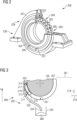
- FIG. 2 shows a bearing arrangement 200 according to an embodiment.
- the bearing arrangement 200 comprises a bearing housing 201.
- the bearing housing 201 houses an interior space 203.
- a bearing 204 is located in the interior space 203.
- the interior space 203 may receive a lubricant, including, but not limited to grease and/or a lubricating oil from a lubricant source.
- the bearing 204 comprises an inner ring, an outer ring and rolling elements 205 which enable the relative rotation between the inner ring and the outer ring.
- the inner ring may be connected to the shaft 105 and the outer ring may be connected to the bearing housing 201.
- the interior space 203 is sealed by a bearing cover 202 on the front side and/or on the rear side of the bearing housing 201 during operation, wherein the front side corresponds, for example, to a side facing or proximal to the gearbox (not explicitly shown and the rear side corresponds, for example, to the side opposite to or distant from the gearbox.
- the front side corresponds to a side facing or proximal to the rotor 108 and the rear side corresponds, for example, to the side opposite to or distant from the rotor 108.
- the bearing housing 201 and in particular the bearing cover 202, comprises an opening 206.
- the opening 206 which may be a drain hole defined in the bearing housing, provides a passage through the bearing housing 201.
- the opening 206 in particular, may be arranged in a lower half of the bearing housing 201 which is next to a bottom 231 of the interior space 203. In one embodiment, the opening 206 may serve as a passageway between the bearing interior space 203 and the bearing exterior.
- the lubricant 300 is provided in the interior space 203 for lubricating the bearing 204 and in particular the rolling elements 205.
- the lubricant 300 in particular comprises grease.
- the lubricant 300 is provided in the interior space 203 with a desired lubricant level 301 ( Figure 3 ).
- the desired lubricant level 301 reaches an upper hemispherical part 229 of the bearing housing 201, which is arranged between the center and the top 232.
- Old or dirty lubricant 300 can be drained via the opening 206 out of the interior space 203. Alternatively or in addition, if too much lubricant 300 is present in the interior space 203, this lubricant 300 can be released through the opening 206 in a controlled manner. With the opening 206, which can also be referred to as "drain hole 206", uncontrolled outflow of the lubricant 300 out of the interior space 203 is avoidable according to embodiments of the disclosure. Further, it can be ensured that a sufficient amount of lubricant 300 is maintained inside the interior space 203 by a chamber 210 which provides a damping effect, thereby throttling the lubricant flow, which will be explained in more detail below. The chamber 210 can also be referred to as sedation chamber 210.
- Figure 3 shows a first example of the chamber 210 which comprises an inlet opening 213 and an outlet opening 214.
- the inlet opening 213 may be fluidically connected to the opening 206.
- the lubricant 300 reaches a damping space 217 ( Figure 5 ) of the chamber 210 via the opening 206 and the inlet opening 213 of the chamber 210.
- the chamber 210 comprises a fluidic connection 211 with the opening 206 such that the opening 206 is in fluidic communication with the damping space 217. This provides a fluidic communication between the interior space 203 and the damping space 217.
- an outlet hose 222 is connected to the outlet opening 214 of the chamber 210.
- a first end 223 of the outlet hose 222 is connected with the outlet opening 214.
- An opposite second end 224 of the outlet hose 222 is in fluidic communication with a collection container 225.
- the collection container 225 is provided for collecting lubricant 300 which gets drained out of the interior space 203 via the chamber 210 and the outlet hose 222.
- the chamber 210 comprises a chamber housing 216 which surrounds the damping space 217.
- the chamber housing 216 defines the damping space 217.
- the chamber housing 216 demarcates the shape of the damping space 217 inside the chamber 210.
- the outlet opening 214 may be located above the inlet opening 213 in a vertical direction. This allows the lubricant entering the chamber 210 via the inlet opening 213 settle inside the chamber 210, thereby losing its momentum and/or energy, resulting in damping. When lubricant fills to a predetermined level inside the chamber 210, it flows out of the outlet opening 214 into the outlet hose 222.
- a cross-section 219 of the damping space 217 is larger than a cross-section 218 of the inlet opening 213.
- the cross-section of the inlet opening 218 is larger than the damping space 219.
- the opening 206 may be located at a lower hemispherical part 230 of the bearing housing 201, which is arranged between the center and the bottom 231.
- the lubricant 300 exits the interior space 203 and enters the damping space 217 via the opening 206 and the inlet opening 213.
- the opening 206 and the inlet opening 213 may serve as a nozzle and/or a throttle.
- the lubricant 300 loses its momentum while it flows from the interior space 203 into the damping space 217.
- the lubricant 300 settles inside the damping space 217.
- the lubricant 300 may lose its momentum and/or energy as it flows through or settles inside the damping space 217.
- the lubricant 300 so collected/settling inside the damping space 217 acts as a barrier for additional lubricant 300 which tries to exit the interior space 203.
- the lubricant 300 If the lubricant 300 reaches the height of the outlet opening 214, which is arranged above the inlet opening 213, the lubricant 300 exits through the outlet hose 222. Because the lubricant 300 has a low viscosity like a plastic fluid, it stays in the damping space 217 if there is no additional impulse or momentum. In other words, the lubricant settled inside the damping space 217 which does not have sufficient momentum and/or energy exhibits resistance to flow out through the outlet hose 222, unless there is additional impulse or momentum. This way, throttling the flow of the lubricant out of the interior space 203 may be attained. In an embodiment, the lubricant 300 does not flow back into the interior space 203.
- the free space in the interior space 203 can be reduced because a higher impulse created by the closed wall next to the moving bearing 204 can be compensated by the chamber 210.
- the reduced free space allows a reduction of the amount of lubricant 300 for the initial filling, which enables cost savings.
- the reduced free space also leads to more movement of the lubricant 300 during operation.
- the lubricant 300 is mixed better and stays more agile. Back-feeding is improved and the overall lubrication regime is improved. This reduces the risk of failure and leads to a higher lifetime of the bearing arrangement 200 and reduces service costs.
- the size of the chamber 200, in particular of the cross-section 218 of the inlet opening 213 and the cross-section 219 of the damping space 217 can be easily adapted, depending on different climates or different types of lubricant 300. Refitting or changes during operation, for example due to field experience, can also be easily carried out.
- the chamber 300 is easily accessible in those examples in which the chamber 210 is arranged at an outside 207 of the bearing housing 201. This allows, for example, lubricant samples to be taken in a more controlled and reproducible way by taking them out of a defined area of the chamber 210 where particles, especially larger ones, will settle down in the damping space 217. These particles, for example, can be collected by a magnet or otherwise out of the chamber 210.
- Figure 4 shows a cross-section of a detail of the bearing arrangement 200.
- the chamber 210 is arranged on a side of the bearing housing 201 which faces the gearbox (not explicitly shown), for example.
- a sealing 233 is arranged to seal the interior space 203 such that the lubricant 300 stays in the interior space 203.
- the chamber 210 is arranged outside of the sealing 233.
- the sealing 233 may be a touch seal which is in direct contact with the shaft 105.
- the sealing 233 can have a shape that reduces the free space between the rolling element 205 and the sealing 233 because the chamber 210 damps pressure fluctuations.
- Figure 5 shows the chamber 210 according to an embodiment.
- Dampers 212 are arranged inside the chamber housing 216 to throttle the lubricant flow through the damping space 217 from the inlet opening 213 to the outlet opening 214.
- Figure 5 shows three dampers 212.
- the number of dampers 212 can be different, for example there is just one single damper 212 provided, two dampers 212 or more than three dampers 212.
- the number of dampers 212 is dependent on a desired damping effect.
- the damper 212 for example, is a baffle. Alternatively, or in addition, the damper 212 is an orifice plate. Alternatively or in addition, the damper 212 is a mesh. Alternatively or in addition, the damper 212 is a gap. Alternatively, or in addition, the damper 212 is a deflector plate. Alternatively, or in addition, the damper 212 is a guide vane. Alternatively, or in addition, the damper 212 may be supported by a spring. Other forms, designs or types of dampers 212 are possible, which are configured and arranged for damping the lubricant flow through the damping space 217.
- dampers 212 inside the chamber 210 can be of the same type or different types of dampers 212 can be arranged inside the chamber 210.
- the damper 212 is aligned transverse to the flow directions of the lubricant.
- the dampers can have different shapes or the same shape.
- the dampers may be plate like having straight edges, or vane like having curved geometry.
- the dampers can be arranged in parallel, in series and/or inclined relative to one another.
- the dampers can be arranged in a staggered, eclipsed and/or inclined manner relative to one another.
- the damping space 217 may be defined by the flow path formed between successive dampers.
- the lubricant flowing through said flow path lose momentum and/or energy leading to damping of pulsations in the lubricant.
- the inlet opening 213 and the outlet opening 214 are arranged spaced apart from one another at a distance 215.
- the outlet opening 214 is arranged above the inlet opening 213.
- FIG. 6 shows a further example of the bearing arrangement 200.
- the chamber 210 comprises a first tube 220 which comprises the inlet opening 213 adjoining the opening 206.
- the first tube 220 comprises a cross-section 221 which is smaller than the cross-section 219 of the damping space 217.
- the first tube 220 is arranged inside the chamber housing 216.
- lubricant 300 enters the damping space 217 via the first tube 220.
- the first tube 220 and the chamber 210 are arranged like a siphon.
- the outlet opening 214 is arranged at the chamber housing 216.
- Dampers 212 are arranged in the damping space 217 between the first tube 220 and the chamber housing 216.
- a vent 227 is provided at a top of the chamber 210, in particular at a top of the chamber housing 216. According to further examples, there is no specific vent 227 provided.
- the vent 227 is provided for evacuating and removing air which, for example, comes out of the interior space 203 into the chamber 210. Air which is transported out of the interior space 203 can be collected and separated inside the chamber housing 216 and eventually evacuated by the vent 227. Thus, too much lubricant outflow due to trapped air can be avoided.
- a main longitudinal extension direction of the chamber housing 216 and the first tube 220 runs along a vertical direction Z.
- the inlet opening 213 and the outlet opening 214 are arranged along a horizontal direction.
- the inlet opening 213 and the outlet opening 214 are arranged opposite to each other along the horizontal direction.
- the outlet opening 214 may be at a different height than the inlet opening 213, for example, slightly above or below the location of the inlet opening 213.
- damping of pulsations in the lubricant may be effectuated by flow of lubricant through the first tube 220 and/or rise of lubricant in the damping space 217 across the dampers 212.
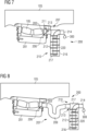
- Figure 7 shows a further example of the bearing arrangement 200.
- the inlet opening 213 is arranged at the chamber housing 216 to adjoin the chamber 210 at one end and to adjoin the opening 206 at the opposite end.
- the first tube 220 housed in the chamber 210 comprises the outlet opening 214.
- lubricant 300 enters the damping space 217 via the inlet opening 213 and rises inside the first tube 220 while it also rises inside the chamber 210 passing through the dampers 212.
- the lubricant 300 exits the chamber housing 216 through the first tube 220 from the outlet opening 214 after passing the dampers 212.
- a hose 209 may be provided between the opening 206 and the inlet opening 213. This is possible in the shown example, according to which the inlet opening 213 is formed in the chamber housing 216.
- the hose 209 can also be provided in the other described examples, for example as shown in Figures 3 and 6 .
- the hose 209 is a flexible hose which is connected between the damping space 217 and the opening 206.
- the hose 209 allows an arrangement of the chamber housing 216 spaced apart from the opening 206 of the bearing housing 201.
- the bearing arrangement 200 may comprise a thermal control module 228.
- the thermal control module 228 comprises a passive thermal insulation.
- the thermal control module 228 comprises an electrical heating and/or cooling.
- the thermal control module 228 is arranged for controlling the temperature inside the chamber housing 216, in particular the temperature of the lubricant 300 in the damping space 217. By controlling the temperature, a desired viscosity and/or other properties of the lubricant 300 can be realized.
- the thermal control module 228 can be provided at the different examples of the bearing arrangement 200 as, for example, shown in the other figures.
- the longitudinal main extension of the chamber 210 may be arranged more horizontal than vertical.
- the chamber housing 216 for example, is connected to the bearing housing 201 at a bottom side of the bearing housing 201.
- the bearing housing 201 comprises one or more apertures 206, 226 which are arranged along the vertical direction Z to connect the interior space 203 with the damping space 217.
- the inlet opening 213 is fluidically connected to the aperture 226.
- Figures 11 to 13 show examples according to which the chamber 210 is arranged inside interior space 203.
- the chamber 210 is integrated in the bearing cover 202. Free space inside the bearing housing 201 can be used as the chamber 210.
- the inlet opening 213 is part of the bearing cover 202 and the lubricant 300 is guided between the inlet opening 213 and the outlet opening 214 along the bearing cover 202. It is also possible to arrange the chamber 210 in the bearing cover 202 at a side opposite to the rolling elements 205 along the horizontal direction.
- a lubricant flow direction 302 of the lubricant 300 is first directed to the left of Figure 13 and then changes such that the lubricant flow direction 302 is directed to the right of Figure 13 before the lubricant 300 exits the damping space 217 through the outlet opening 214.
- Figure 14 shows an embodiment of the bearing arrangement 200 in which the chamber 210 is arranged along an axial direction of the shaft 105.
- the chamber housing 216 can be arranged independent from the bearing housing 201, spaced apart from the bearing housing 201.
- the chamber 210 can be formed in the style of a muffler, wherein the cross-section 219 of the damping space 217 is larger than the cross-section 218 of the inlet opening 213 and, for example, of the hose 209.
- the bearing arrangement 200 with the chamber 210, provides the damping space 217. This reduces the risk of failure of the bearing 204. Outflow of the lubricant 300 can be controlled and thereby the amount of lubricant 300 can be increased and the lubricant level 301 can be kept at a desired height.
Landscapes
- Engineering & Computer Science (AREA)
- General Engineering & Computer Science (AREA)
- Mechanical Engineering (AREA)
- Life Sciences & Earth Sciences (AREA)
- Sustainable Development (AREA)
- Sustainable Energy (AREA)
- Chemical & Material Sciences (AREA)
- Combustion & Propulsion (AREA)
- Support Of The Bearing (AREA)
Abstract
- a bearing (204),
- a bearing housing (201), wherein the bearing housing (201) houses an interior space (203) in which the bearing (204) is arranged, and wherein the bearing housing (201) comprises an opening (206) for draining lubricant (300) from the interior space (203),
- a chamber (210), wherein the chamber (210) comprises a fluidic connection (211) with the opening (206), wherein a damping space (217) is formed inside the chamber (210) to throttle a lubricant flow out of the interior space (203).
Description
- The disclosure relates to a bearing arrangement for a wind turbine, in particular to a rotor bearing arrangement. The disclosure further relates to a wind turbine, in particular to a wind turbine which comprises a bearing arrangement as described herein.
- A wind turbine may include a rotor that includes a rotatable rotor assembly having multiple rotor blades. The rotor blades transform wind energy into a drive torque that drives the generator via a drive train.
- It is desirable to provide a bearing arrangement which provides a reliable operation. It is further desirable to provide a wind turbine which provides a reliable operation.
- Embodiments of the disclosure provide a bearing arrangement for a wind turbine. The bearing arrangement comprises a bearing. The bearing arrangement comprises a bearing housing. The bearing housing houses an interior space in which the bearing is arranged. The bearing housing comprises an opening configured to drain lubricant from the interior space. The bearing arrangement comprises a chamber. The chamber comprises a fluidic connection with the opening. A damping space is formed inside the chamber. In particular, the damping space is arranged inside the chamber. In particular, the damping space is defined by the chamber. The damping space is arranged inside the chamber to throttle a lubricant flow out of the interior space.
- For example, the bearing arrangement is a rotor bearing arrangement of a wind turbine. In one embodiment, the rotor bearing arrangement comprising the chamber to throttle a lubricant flow out of the interior space may correspond to both the rotor side bearing and the gearbox side bearing. The bearing arrangement and in particular the bearing is, for example, lubricated with grease or another lubricant, like an oil. It is important to contain a desired amount of lubricant inside the bearing housing in the interior space. Insufficient amount of lubricant in the bearing leads to higher wear and premature failure. On the other hand, high splashing losses lead to temperature raise and therefore reduced base viscosity which leads to lower film thickness, and eventually, to premature failure. Thus, it is important to ensure sufficient lubrication and to avoid lubricant starvation and to keep splashing losses low. An uncontrolled lubricant leakage should be avoided, in particular a leakage through a sealing of the bearing arrangement. Therefore, the opening is provided to allow a controlled draining of the lubricant.
- The chamber with the damping space of the disclosure acts like a choke or a throttle to dampen the outflow of the lubricant. During operation, thelubricant, as it flows through the chamber, loses its momentum and/or energy. The lubricant settles down and forms a kind of a barrier for lubricant coming out of the interior space. The lubricant, in particular, is not flowing like a Newtoninan fluid, but rather like a structural viscous or even plastic fluid. This means, for example, that the lubricant is able to stay in a certain form and position without flowing away until a sufficient impulse or momentum occurs that triggers the movement. Thus, the chamber allows an outflow of lubricant in a controlled manner, wherein an undesirably high outflow of lubricant can be avoided. The amount of lubricant inside the bearing can be reliably kept within given thresholds. The choice of shape and dimensions of the chamber may depend on the capacity of the bearing housing, such that the impulses generated in the lubricant by the rotating bearing may be minimized to desired extents based on operational characteristics.
- According to an embodiment, the chamber is arranged at least partly outside of the bearing housing. Alternatively or in addition, the chamber is arranged at least partly inside the bearing housing. It is possible to arrange the chamber at a free space of the bearing housing depending on the design of the bearing housing and the bearing arrangement. Thus, available space can be used efficiently.
- According to an embodiment, the chamber comprises an inlet opening and an outlet opening. The inlet opening is connectable to the opening. Lubricant which flows out of the interior space can be reliably transferred to the chamber via the inlet opening. Lubricant which exits the chamber can be reliably guided to a collection container via the outlet opening.
- According to an embodiment, a cross-section of the inlet opening of the chamber is different from a cross-section of the damping space. It is possible that the cross-section of the inlet opening is smaller than the cross-section of the damping space. Alternatively, the cross-section of the inlet opening is larger than the cross-section of the damping space. According to an embodiment, the chamber comprises a first tube. The first tube is connectable to one of the inlet opening and the outlet opening. The other of the inlet opening and the outlet opening is in fluid communication with the damping space. The first tube comprises a cross-section that is different from the cross-section of the damping space. Thus, the chamber can be designed like a siphon.
- According to embodiments, the bearing arrangement comprises a hose. The hose is fluidically connectable between the chamber and the opening. This allows freedom for the arrangement of the chamber relative to the opening and the bearing housing.
- According to embodiments, the bearing arrangement comprises an outlet hose. The outlet hose is fluidically connectable to the chamber at a first end. The outlet hose comprises a second end for releasing the lubricant into the collection container. This allows an arrangement of the outlet opening at a distance from the collection container.
- According to an embodiment, at least one aperture is defined in the bearing housing. The opening is in fluid communication with the chamber through the at least one aperture. For example, the aperture is a hole in the bearing housing.
- According to an embodiment, the chamber comprises a vent. The chamber can be vented in a controlled manner by the use of the vent.
- According to an embodiment, the bearing arrangement comprises a thermal control module for regulating a chamber temperature. For example, the thermal control module comprises an insulation for insulating the chamber such that the interior of the chamber can be kept warmer than the outside. Alternatively or in addition, the thermal control module comprises a heater for heating the chamber. Alternatively or in addition, the thermal control module comprises a cooler for cooling the chamber. Thus, the thermal control module allows control of the temperature of the chamber depending on external environmental conditions in order to maintain at least one of a desired density, viscosity and other properties of the lubricant.
- According to embodiments, the bearing arrangement comprises a damper. The damper is arranged inside the chamber. For example, the damper comprises at least one of a baffle, an orifice plate, a mesh, a gap, a deflector plate, and a guide vane. A desired damping effect and throttle of the lubricant flow can be realized with the damper. The damper, for example, is selected dependent on environmental conditions at the installation side of the wind turbine and/or the type of lubricant used.
- According to embodiments, the damper comprises a plurality of dampers which are arranged inside the chamber. The dampers can be of the same type or of different types. The dampers can have different shapes or the same shape. The dampers can be arranged in parallel, in series and/or inclined relative to one another. The dampers can be arranged in a staggered, eclipsed and/or inclined manner.
- According to embodiments, the damper comprises a spring that is biased towards the opening. The spring provides a resisting force acting against the lubricant flow out of the interior space. Thus, the pressure and momentum of the lubricant can be controlled by the spring. It is possible to have a spring with an adjustable preload such that the bias of the spring is controllable and adjustable during operation. Alternatively or in addition, the damper comprises a baffle or a plurality of baffles that can be moved to control a resisting force against the lubricant flow. For example, the baffle is connected to the spring and pivotable around a pin joint. If the flow and/or the pressure is high, for example, the baffles are moved such that a gap for the lubricant flow is smaller or even closed to stop the lubricant flow. Thus, control of the lubricant flow is possible by adjusting the degree of deflection of the buffer.
- Further embodiments of the disclosure provide a wind turbine, wherein the wind turbine comprises a nacelle. The wind turbine comprises a bearing arrangement according to one of the described embodiments. The bearing arrangement is arranged within the nacelle.
- The present invention will be further described with reference to the accompanying drawings. In the drawings, elements of the same structure and/or functionality may be referred to by the same reference signs. It is to be understood that embodiments showing the figures are illustrative representations and are not necessarily drawn to scale.
-
Figure 1 is a schematic view of a wind turbine according to an embodiment. -
Figures 2 to 14 are schematic views of rotor bearing arrangements and details thereof according to different embodiments. - While the invention is amenable to various modifications and alternative forms, specifics thereof have been shown by way of examples in the drawings and will be described in detail. It should be understood, however, that the intention is not to limit the invention to the particular embodiments described. On the contrary, the intention is to cover all modifications, equivalents, and alternatives falling within the scope of the invention defining by the appended claims.
- As shown in
Figure 1 , awind turbine 100 comprises atower 102. Thetower 102 is connected to afoundation 104 fixed on a ground. Thefoundation 104 is formed in and supported by the ground. Anacelle 106 is arranged on a top end of thetower 102 opposite to thefoundation 104. Thenacelle 106 houses the drive train, among other components and subassemblies. Inside thenacelle 106, for example, a generator is arranged which is connected via the drive train to arotor 108. The drive train comprises, for example, a gearbox and a rotor shaft 105 (Figure 3 ). Therotor 108 comprisesseveral rotor blades 110. Therotor blades 110 are mounted on arotor hub 112. Therotor hub 112 is connected to therotor shaft 105. - The
rotor 108 is driven in operation by an airflow, for example wind. The rotational movement of therotor 108 is transmitted via the drive train to the generator. The generator converts the mechanical output of therotor 108 into electrical energy. - The
wind turbine 100 comprises abearing arrangement 200. According to the shown embodiments thebearing arrangement 200 is a rotor bearing arrangement. Therotor shaft 105 is rotatably supported by thebearing arrangement 200. In one embodiment, therotor bearing arrangement 200 may correspond to both the rotor side bearing arrangement and the gearbox side bearing arrangement, supporting the shaft at the rotor side and the gearbox side, respectively. -
Figure 2 shows abearing arrangement 200 according to an embodiment. Thebearing arrangement 200 comprises a bearinghousing 201. The bearinghousing 201 houses aninterior space 203. Abearing 204 is located in theinterior space 203. Theinterior space 203 may receive a lubricant, including, but not limited to grease and/or a lubricating oil from a lubricant source. - The
bearing 204 comprises an inner ring, an outer ring and rollingelements 205 which enable the relative rotation between the inner ring and the outer ring. The inner ring may be connected to theshaft 105 and the outer ring may be connected to the bearinghousing 201. - The
interior space 203 is sealed by abearing cover 202 on the front side and/or on the rear side of the bearinghousing 201 during operation, wherein the front side corresponds, for example, to a side facing or proximal to the gearbox (not explicitly shown and the rear side corresponds, for example, to the side opposite to or distant from the gearbox. According to a further example, the front side corresponds to a side facing or proximal to therotor 108 and the rear side corresponds, for example, to the side opposite to or distant from therotor 108. - The bearing
housing 201, and in particular thebearing cover 202, comprises anopening 206. Theopening 206, which may be a drain hole defined in the bearing housing, provides a passage through the bearinghousing 201. Theopening 206, in particular, may be arranged in a lower half of the bearinghousing 201 which is next to abottom 231 of theinterior space 203. In one embodiment, theopening 206 may serve as a passageway between the bearinginterior space 203 and the bearing exterior. - The
lubricant 300 is provided in theinterior space 203 for lubricating thebearing 204 and in particular the rollingelements 205. Thelubricant 300 in particular comprises grease. - The
lubricant 300 is provided in theinterior space 203 with a desired lubricant level 301 (Figure 3 ). In particular, the desiredlubricant level 301 reaches an upperhemispherical part 229 of the bearinghousing 201, which is arranged between the center and the top 232. - Old or
dirty lubricant 300 can be drained via theopening 206 out of theinterior space 203. Alternatively or in addition, if toomuch lubricant 300 is present in theinterior space 203, thislubricant 300 can be released through theopening 206 in a controlled manner. With theopening 206, which can also be referred to as "drain hole 206", uncontrolled outflow of thelubricant 300 out of theinterior space 203 is avoidable according to embodiments of the disclosure. Further, it can be ensured that a sufficient amount oflubricant 300 is maintained inside theinterior space 203 by achamber 210 which provides a damping effect, thereby throttling the lubricant flow, which will be explained in more detail below. Thechamber 210 can also be referred to assedation chamber 210. -
Figure 3 shows a first example of thechamber 210 which comprises aninlet opening 213 and anoutlet opening 214. Theinlet opening 213 may be fluidically connected to theopening 206. Thus, thelubricant 300 reaches a damping space 217 (Figure 5 ) of thechamber 210 via theopening 206 and the inlet opening 213 of thechamber 210. Thechamber 210 comprises afluidic connection 211 with theopening 206 such that theopening 206 is in fluidic communication with the dampingspace 217. This provides a fluidic communication between theinterior space 203 and the dampingspace 217. - For example, an
outlet hose 222 is connected to the outlet opening 214 of thechamber 210. Afirst end 223 of theoutlet hose 222 is connected with theoutlet opening 214. An oppositesecond end 224 of theoutlet hose 222 is in fluidic communication with acollection container 225. Thecollection container 225 is provided for collectinglubricant 300 which gets drained out of theinterior space 203 via thechamber 210 and theoutlet hose 222. - The
chamber 210 comprises achamber housing 216 which surrounds the dampingspace 217. Thechamber housing 216 defines the dampingspace 217. In an embodiment, thechamber housing 216 demarcates the shape of the dampingspace 217 inside thechamber 210. Further, in the exemplary embodiment shown inFIG. 3 , theoutlet opening 214 may be located above the inlet opening 213 in a vertical direction. This allows the lubricant entering thechamber 210 via theinlet opening 213 settle inside thechamber 210, thereby losing its momentum and/or energy, resulting in damping. When lubricant fills to a predetermined level inside thechamber 210, it flows out of theoutlet opening 214 into theoutlet hose 222. - According to the example of
Figure 3 , across-section 219 of the dampingspace 217 is larger than across-section 218 of theinlet opening 213. According to further examples, the cross-section of theinlet opening 218 is larger than the dampingspace 219. - The
opening 206 may be located at a lowerhemispherical part 230 of the bearinghousing 201, which is arranged between the center and the bottom 231. - During operation, the
lubricant 300 exits theinterior space 203 and enters the dampingspace 217 via theopening 206 and theinlet opening 213. Theopening 206 and theinlet opening 213 may serve as a nozzle and/or a throttle. Thelubricant 300 loses its momentum while it flows from theinterior space 203 into the dampingspace 217. Thelubricant 300 settles inside the dampingspace 217. In an embodiment, thelubricant 300 may lose its momentum and/or energy as it flows through or settles inside the dampingspace 217. Thelubricant 300 so collected/settling inside the dampingspace 217 acts as a barrier foradditional lubricant 300 which tries to exit theinterior space 203. If thelubricant 300 reaches the height of theoutlet opening 214, which is arranged above theinlet opening 213, thelubricant 300 exits through theoutlet hose 222. Because thelubricant 300 has a low viscosity like a plastic fluid, it stays in the dampingspace 217 if there is no additional impulse or momentum. In other words, the lubricant settled inside the dampingspace 217 which does not have sufficient momentum and/or energy exhibits resistance to flow out through theoutlet hose 222, unless there is additional impulse or momentum. This way, throttling the flow of the lubricant out of theinterior space 203 may be attained. In an embodiment, thelubricant 300 does not flow back into theinterior space 203. - By entering the comparatively large damping
space 217 with thecross-section 219 through the comparablysmall openings cross-section 218, the impulses provided by the movingbearing 204 are significantly choked. Thus, an outflow oflubricant 300 caused by these impulses is damped. - With the
chamber 210, the free space in theinterior space 203 can be reduced because a higher impulse created by the closed wall next to the movingbearing 204 can be compensated by thechamber 210. The reduced free space allows a reduction of the amount oflubricant 300 for the initial filling, which enables cost savings. The reduced free space also leads to more movement of thelubricant 300 during operation. Thus, thelubricant 300 is mixed better and stays more agile. Back-feeding is improved and the overall lubrication regime is improved. This reduces the risk of failure and leads to a higher lifetime of thebearing arrangement 200 and reduces service costs. - The size of the
chamber 200, in particular of thecross-section 218 of theinlet opening 213 and thecross-section 219 of the dampingspace 217 can be easily adapted, depending on different climates or different types oflubricant 300. Refitting or changes during operation, for example due to field experience, can also be easily carried out. Thechamber 300 is easily accessible in those examples in which thechamber 210 is arranged at an outside 207 of the bearinghousing 201. This allows, for example, lubricant samples to be taken in a more controlled and reproducible way by taking them out of a defined area of thechamber 210 where particles, especially larger ones, will settle down in the dampingspace 217. These particles, for example, can be collected by a magnet or otherwise out of thechamber 210. -
Figure 4 shows a cross-section of a detail of thebearing arrangement 200. Thechamber 210 is arranged on a side of the bearinghousing 201 which faces the gearbox (not explicitly shown), for example. A sealing 233 is arranged to seal theinterior space 203 such that thelubricant 300 stays in theinterior space 203. Thechamber 210 is arranged outside of the sealing 233. In particular, the sealing 233 may be a touch seal which is in direct contact with theshaft 105. The sealing 233 can have a shape that reduces the free space between the rollingelement 205 and the sealing 233 because thechamber 210 damps pressure fluctuations. -
Figure 5 shows thechamber 210 according to an embodiment.Dampers 212 are arranged inside thechamber housing 216 to throttle the lubricant flow through the dampingspace 217 from the inlet opening 213 to theoutlet opening 214.Figure 5 shows threedampers 212. The number ofdampers 212 can be different, for example there is just onesingle damper 212 provided, twodampers 212 or more than threedampers 212. The number ofdampers 212 is dependent on a desired damping effect. - The
damper 212, for example, is a baffle. Alternatively, or in addition, thedamper 212 is an orifice plate. Alternatively or in addition, thedamper 212 is a mesh. Alternatively or in addition, thedamper 212 is a gap. Alternatively, or in addition, thedamper 212 is a deflector plate. Alternatively, or in addition, thedamper 212 is a guide vane. Alternatively, or in addition, thedamper 212 may be supported by a spring. Other forms, designs or types ofdampers 212 are possible, which are configured and arranged for damping the lubricant flow through the dampingspace 217. Alldampers 212 inside thechamber 210 can be of the same type or different types ofdampers 212 can be arranged inside thechamber 210. For example, thedamper 212 is aligned transverse to the flow directions of the lubricant. The dampers can have different shapes or the same shape. For instance, the dampers may be plate like having straight edges, or vane like having curved geometry. Further, the dampers can be arranged in parallel, in series and/or inclined relative to one another. Furthermore, the dampers can be arranged in a staggered, eclipsed and/or inclined manner relative to one another. - In an embodiment, the damping
space 217 may be defined by the flow path formed between successive dampers. The lubricant flowing through said flow path lose momentum and/or energy leading to damping of pulsations in the lubricant. - The
inlet opening 213 and theoutlet opening 214 are arranged spaced apart from one another at adistance 215. In particular, theoutlet opening 214 is arranged above theinlet opening 213. -
Figure 6 shows a further example of thebearing arrangement 200. Thechamber 210 comprises afirst tube 220 which comprises the inlet opening 213 adjoining theopening 206. Thefirst tube 220 comprises across-section 221 which is smaller than thecross-section 219 of the dampingspace 217. Thefirst tube 220 is arranged inside thechamber housing 216. During operation,lubricant 300 enters the dampingspace 217 via thefirst tube 220. Thefirst tube 220 and thechamber 210 are arranged like a siphon. Theoutlet opening 214 is arranged at thechamber housing 216.Dampers 212 are arranged in the dampingspace 217 between thefirst tube 220 and thechamber housing 216. - A
vent 227 is provided at a top of thechamber 210, in particular at a top of thechamber housing 216. According to further examples, there is nospecific vent 227 provided. Thevent 227 is provided for evacuating and removing air which, for example, comes out of theinterior space 203 into thechamber 210. Air which is transported out of theinterior space 203 can be collected and separated inside thechamber housing 216 and eventually evacuated by thevent 227. Thus, too much lubricant outflow due to trapped air can be avoided. - A main longitudinal extension direction of the
chamber housing 216 and thefirst tube 220 runs along a vertical direction Z. Theinlet opening 213 and theoutlet opening 214 are arranged along a horizontal direction. Theinlet opening 213 and theoutlet opening 214 are arranged opposite to each other along the horizontal direction. In an embodiment, theoutlet opening 214 may be at a different height than theinlet opening 213, for example, slightly above or below the location of theinlet opening 213. In another embodiment, damping of pulsations in the lubricant may be effectuated by flow of lubricant through thefirst tube 220 and/or rise of lubricant in the dampingspace 217 across thedampers 212. -
Figure 7 shows a further example of thebearing arrangement 200. Theinlet opening 213 is arranged at thechamber housing 216 to adjoin thechamber 210 at one end and to adjoin theopening 206 at the opposite end. Thefirst tube 220 housed in thechamber 210 comprises theoutlet opening 214. During operation,lubricant 300 enters the dampingspace 217 via theinlet opening 213 and rises inside thefirst tube 220 while it also rises inside thechamber 210 passing through thedampers 212. Thelubricant 300 exits thechamber housing 216 through thefirst tube 220 from theoutlet opening 214 after passing thedampers 212. - In a further embodiment shown in
Figure 8 , ahose 209 may be provided between theopening 206 and theinlet opening 213. This is possible in the shown example, according to which theinlet opening 213 is formed in thechamber housing 216. Thehose 209 can also be provided in the other described examples, for example as shown inFigures 3 and6 . - In particular, the
hose 209 is a flexible hose which is connected between the dampingspace 217 and theopening 206. Thehose 209 allows an arrangement of thechamber housing 216 spaced apart from theopening 206 of the bearinghousing 201. - As shown in
Figure 9 , thebearing arrangement 200 may comprise athermal control module 228. According to embodiments, thethermal control module 228 comprises a passive thermal insulation. Alternatively or in addition, thethermal control module 228 comprises an electrical heating and/or cooling. Thethermal control module 228 is arranged for controlling the temperature inside thechamber housing 216, in particular the temperature of thelubricant 300 in the dampingspace 217. By controlling the temperature, a desired viscosity and/or other properties of thelubricant 300 can be realized. Thethermal control module 228 can be provided at the different examples of thebearing arrangement 200 as, for example, shown in the other figures. - As shown in
Figure 10 , the longitudinal main extension of thechamber 210 may be arranged more horizontal than vertical. Thechamber housing 216, for example, is connected to the bearinghousing 201 at a bottom side of the bearinghousing 201. - The bearing
housing 201 comprises one ormore apertures 206, 226 which are arranged along the vertical direction Z to connect theinterior space 203 with the dampingspace 217. Theinlet opening 213 is fluidically connected to the aperture 226. -
Figures 11 to 13 show examples according to which thechamber 210 is arranged insideinterior space 203. For example, thechamber 210 is integrated in thebearing cover 202. Free space inside the bearinghousing 201 can be used as thechamber 210. Theinlet opening 213 is part of thebearing cover 202 and thelubricant 300 is guided between theinlet opening 213 and theoutlet opening 214 along thebearing cover 202. It is also possible to arrange thechamber 210 in thebearing cover 202 at a side opposite to the rollingelements 205 along the horizontal direction. - As shown in
Figure 13 , it is also possible to increase the length of the dampingspace 217 inside thebearing cover 202 by providing a channel design which comprises a direction change or a plurality of direction changes. Starting at theinlet opening 213, alubricant flow direction 302 of thelubricant 300 is first directed to the left ofFigure 13 and then changes such that thelubricant flow direction 302 is directed to the right ofFigure 13 before thelubricant 300 exits the dampingspace 217 through theoutlet opening 214. -
Figure 14 shows an embodiment of thebearing arrangement 200 in which thechamber 210 is arranged along an axial direction of theshaft 105. Thechamber housing 216 can be arranged independent from the bearinghousing 201, spaced apart from the bearinghousing 201. Thechamber 210 can be formed in the style of a muffler, wherein thecross-section 219 of the dampingspace 217 is larger than thecross-section 218 of theinlet opening 213 and, for example, of thehose 209. - The
bearing arrangement 200, with thechamber 210, provides the dampingspace 217. This reduces the risk of failure of thebearing 204. Outflow of thelubricant 300 can be controlled and thereby the amount oflubricant 300 can be increased and thelubricant level 301 can be kept at a desired height. -
- 100
- wind turbine
- 102
- tower
- 104
- foundation
- 105
- shaft
- 106
- nacelle
- 108
- rotor
- 110
- rotor blade
- 112
- rotor hub
- 200
- bearing arrangement
- 201
- bearing housing
- 202
- bearing cover
- 203
- interior space
- 204
- bearing
- 205
- rolling element
- 206
- opening
- 207
- outside
- 209
- hose
- 210
- chamber
- 211
- fluidic connection
- 212
- damper
- 213
- inlet opening
- 214
- outlet opening
- 215
- distance between openings
- 216
- chamber housing
- 217
- damping space
- 218
- cross-section of inlet opening
- 219
- cross-section of damping space
- 220
- first tube
- 221
- cross-section of inner tube
- 222
- outlet hose
- 223
- first end
- 224
- second end
- 225
- collection container
- 226
- aperture
- 227
- vent
- 228
- thermal control module
- 229
- upper part
- 230
- lower part
- 231
- bottom
- 232
- top
- 233
- sealing
- 300
- lubricant
- 301
- lubricant level
- 302
- lubricant flow direction
- Z
- vertical direction
Claims (15)
- Bearing arrangement (200) for a wind turbine (100), comprising- a bearing (204),- a bearing housing (201), wherein the bearing housing (201) houses an interior space (203) in which the bearing (204) is arranged, and wherein the bearing housing (201) comprises an opening (206) for draining lubricant (300) from the interior space (203),- a chamber (210), wherein the chamber (210) comprises a fluidic connection (211) with the opening (206), wherein a damping space (217) is formed inside the chamber (210) to throttle a lubricant flow out of the interior space (203).
- Bearing arrangement according to claim 1, wherein the chamber (210) is arranged outside (207) of the bearing housing (201) and/or inside the bearing housing (201).
- Bearing arrangement according to claim 1 or 2, wherein the chamber (210) comprises an inlet opening (213) and an outlet opening (214), wherein the inlet opening (213) is connectable to the opening (206).
- Bearing arrangement according to claim 3, wherein a cross-section (218) of the inlet opening (213) of the chamber (210) is different from a cross-section (219) of the damping space (217) .
- Bearing arrangement according to claim 3 or 4, wherein the chamber (210) comprises a first tube (220) connectable to one of the inlet opening (213) and the outlet opening (214), such that the damping space (217) is in fluid communication with other of the inlet opening (213) and the outlet opening (214), and wherein the first tube (220) comprises a cross-section (221) that is different from the cross-section (219) of the damping space (217).
- Bearing arrangement according to any one of claims 1 to 5, comprising a hose (209), wherein the hose (209) is fluidically connectable between the chamber (210) and the opening (206).
- Bearing arrangement according to any one of claims 1 to 6, comprising an outlet hose (222), wherein the outlet hose (222) is fluidically connectable to the chamber (210) at a first end (223), and comprises a second end (224) for releasing the lubricant into a collection container (225).
- Bearing arrangement according to any one of claims 1 to 7, wherein the opening (206) is in fluid communication with the chamber (210) through at least one aperture (226) defined in the bearing housing (201).
- Bearing arrangement according to any one of claims 1 to 8, wherein the chamber (210) comprises a vent (227).
- Bearing arrangement according to any one of claims 1 to 9, comprising a thermal control module (228) for regulating a chamber (210) temperature.
- Bearing arrangement according to any one of claims 1 to 10, comprising a damper (212), wherein the damper (212) is arranged inside the chamber (210) and comprises at least one of a baffle, an orifice plate, a mesh, a gap, a deflector plate, and a guide vane.
- Bearing arrangement according to claim 11, wherein the damper (212) comprises a spring that is biased towards the opening (206).
- Bearing arrangement according to claim 11 or 12, wherein the damper (212) is movably arranged inside the chamber (210) for adjusting the throttle depending on the position of the damper (212).
- Bearing arrangement according to any one of claims 1 to 13, wherein a plurality of dampers (212) is arranged inside the chamber (210), wherein the dampers are arranged in parallel, in series and/or inclined relative to one another.
- Wind turbine, comprising- a nacelle (106);- a bearing arrangement (200) according to any one of claims 1 to 14 which is arranged within the nacelle (106).
Priority Applications (2)
| Application Number | Priority Date | Filing Date | Title |
|---|---|---|---|
| EP23174816.1A EP4467830B1 (en) | 2023-05-23 | 2023-05-23 | Bearing arrangement for a wind turbine and wind turbine |
| US18/669,260 US20240392756A1 (en) | 2023-05-23 | 2024-05-20 | Bearing arrangement for a wind turbine and wind turbine |
Applications Claiming Priority (1)
| Application Number | Priority Date | Filing Date | Title |
|---|---|---|---|
| EP23174816.1A EP4467830B1 (en) | 2023-05-23 | 2023-05-23 | Bearing arrangement for a wind turbine and wind turbine |
Publications (3)
| Publication Number | Publication Date |
|---|---|
| EP4467830A1 true EP4467830A1 (en) | 2024-11-27 |
| EP4467830B1 EP4467830B1 (en) | 2026-04-08 |
| EP4467830C0 EP4467830C0 (en) | 2026-04-08 |
Family
ID=86497670
Family Applications (1)
| Application Number | Title | Priority Date | Filing Date |
|---|---|---|---|
| EP23174816.1A Active EP4467830B1 (en) | 2023-05-23 | 2023-05-23 | Bearing arrangement for a wind turbine and wind turbine |
Country Status (2)
| Country | Link |
|---|---|
| US (1) | US20240392756A1 (en) |
| EP (1) | EP4467830B1 (en) |
Citations (5)
| Publication number | Priority date | Publication date | Assignee | Title |
|---|---|---|---|---|
| EP1710432A1 (en) * | 2000-09-25 | 2006-10-11 | Harakosan Co. Ltd. | Wind power generator |
| US20100322543A1 (en) * | 2006-05-23 | 2010-12-23 | Lincoln Gmbh | Bearing arrangement and metering valve and suction device therefor |
| EP2657556A2 (en) * | 2012-04-26 | 2013-10-30 | Jtekt Corporation | Grease supply system for rolling bearing |
| US20220042592A1 (en) * | 2018-09-27 | 2022-02-10 | Zf Friedrichshafen Ag | Measuring arrangement for lubricant |
| EP4166802A1 (en) * | 2021-10-18 | 2023-04-19 | Siemens Gamesa Renewable Energy A/S | Fluid container for bearings |
Family Cites Families (3)
| Publication number | Priority date | Publication date | Assignee | Title |
|---|---|---|---|---|
| US3683673A (en) * | 1971-04-29 | 1972-08-15 | Gen Motors Corp | Non-destructive test apparatus and method for grease packed bearings |
| JP5053719B2 (en) * | 2007-06-07 | 2012-10-17 | オークマ株式会社 | Bearing lubrication equipment |
| FR3071548B1 (en) * | 2017-09-22 | 2021-09-10 | Safran Trans Systems | TURBOMACHINE BEARING LUBRICATION AND COOLING DEVICE |
-
2023
- 2023-05-23 EP EP23174816.1A patent/EP4467830B1/en active Active
-
2024
- 2024-05-20 US US18/669,260 patent/US20240392756A1/en active Pending
Patent Citations (5)
| Publication number | Priority date | Publication date | Assignee | Title |
|---|---|---|---|---|
| EP1710432A1 (en) * | 2000-09-25 | 2006-10-11 | Harakosan Co. Ltd. | Wind power generator |
| US20100322543A1 (en) * | 2006-05-23 | 2010-12-23 | Lincoln Gmbh | Bearing arrangement and metering valve and suction device therefor |
| EP2657556A2 (en) * | 2012-04-26 | 2013-10-30 | Jtekt Corporation | Grease supply system for rolling bearing |
| US20220042592A1 (en) * | 2018-09-27 | 2022-02-10 | Zf Friedrichshafen Ag | Measuring arrangement for lubricant |
| EP4166802A1 (en) * | 2021-10-18 | 2023-04-19 | Siemens Gamesa Renewable Energy A/S | Fluid container for bearings |
Also Published As
| Publication number | Publication date |
|---|---|
| EP4467830B1 (en) | 2026-04-08 |
| US20240392756A1 (en) | 2024-11-28 |
| EP4467830C0 (en) | 2026-04-08 |
Similar Documents
| Publication | Publication Date | Title |
|---|---|---|
| CN102439333B (en) | Lubricating oil supply device | |
| DE112007000304B4 (en) | Clutch unit with wet-running clutch | |
| EP2538055B1 (en) | Oil bypass channel deaerator for a geared turbofan engine | |
| JP5031031B2 (en) | Wind power generator | |
| JP4581583B2 (en) | Transmission lubrication structure | |
| EP3808976B1 (en) | A gearbox system for a wind turbine, wind turbine with a gearbox system, and method for operating a gearbox system | |
| CN102362102A (en) | reducer | |
| CN102365476A (en) | Transmission | |
| CN102362101A (en) | reducer | |
| KR102179740B1 (en) | Separator device for separating lubricant from coolant fluid | |
| US9816601B2 (en) | Lubrication system with passive valve | |
| US8425394B2 (en) | Centrifugal separator with lubrication device | |
| CN102365475A (en) | Reducer at least partially filled with oil | |
| CN219119448U (en) | Fluid guide member for compressor and compressor | |
| EP3739205B1 (en) | Bearing arrangement for a wind turbine and wind turbine | |
| EP4467830B1 (en) | Bearing arrangement for a wind turbine and wind turbine | |
| JP3969742B2 (en) | Apparatus and method for discharging liquid lubricant from bearing apparatus | |
| EP2778478B1 (en) | Lubrication system with passive drain valve | |
| US12422037B2 (en) | Drive assembly and vehicle having such a drive assembly | |
| EP4467808A1 (en) | Bearing arrangement for a wind turbine and wind turbine | |
| WO2019147778A1 (en) | Journal bearing assembly with drainage facilitation element | |
| WO2003006828A1 (en) | Compressor | |
| WO2023160769A1 (en) | An oil cooler, a wind turbine comprising an oil cooler and a method for cooling oil | |
| CN103958896A (en) | Compressors, engines or pumps with pistons moving in translation along an annular path | |
| EP3656995B1 (en) | Turbocharger |
Legal Events
| Date | Code | Title | Description |
|---|---|---|---|
| PUAI | Public reference made under article 153(3) epc to a published international application that has entered the european phase |
Free format text: ORIGINAL CODE: 0009012 |
|
| STAA | Information on the status of an ep patent application or granted ep patent |
Free format text: STATUS: THE APPLICATION HAS BEEN PUBLISHED |
|
| AK | Designated contracting states |
Kind code of ref document: A1 Designated state(s): AL AT BE BG CH CY CZ DE DK EE ES FI FR GB GR HR HU IE IS IT LI LT LU LV MC ME MK MT NL NO PL PT RO RS SE SI SK SM TR |
|
| STAA | Information on the status of an ep patent application or granted ep patent |
Free format text: STATUS: REQUEST FOR EXAMINATION WAS MADE |
|
| 17P | Request for examination filed |
Effective date: 20250522 |
|
| GRAP | Despatch of communication of intention to grant a patent |
Free format text: ORIGINAL CODE: EPIDOSNIGR1 |
|
| STAA | Information on the status of an ep patent application or granted ep patent |
Free format text: STATUS: GRANT OF PATENT IS INTENDED |
|
| RIC1 | Information provided on ipc code assigned before grant |
Ipc: F16C 19/52 20060101AFI20251203BHEP Ipc: F03D 80/70 20160101ALI20251203BHEP Ipc: F16C 23/08 20060101ALI20251203BHEP Ipc: F16C 33/66 20060101ALI20251203BHEP |
|
| INTG | Intention to grant announced |
Effective date: 20251218 |
|
| GRAS | Grant fee paid |
Free format text: ORIGINAL CODE: EPIDOSNIGR3 |
|
| GRAA | (expected) grant |
Free format text: ORIGINAL CODE: 0009210 |
|
| STAA | Information on the status of an ep patent application or granted ep patent |
Free format text: STATUS: THE PATENT HAS BEEN GRANTED |
|
| AK | Designated contracting states |
Kind code of ref document: B1 Designated state(s): AL AT BE BG CH CY CZ DE DK EE ES FI FR GB GR HR HU IE IS IT LI LT LU LV MC ME MK MT NL NO PL PT RO RS SE SI SK SM TR |
|
| REG | Reference to a national code |
Ref country code: CH Ref legal event code: F10 Free format text: ST27 STATUS EVENT CODE: U-0-0-F10-F00 (AS PROVIDED BY THE NATIONAL OFFICE) Effective date: 20260408 Ref country code: GB Ref legal event code: FG4D |
|
| REG | Reference to a national code |
Ref country code: DE Ref legal event code: R096 Ref document number: 602023014721 Country of ref document: DE |
|
| REG | Reference to a national code |
Ref country code: IE Ref legal event code: FG4D |
|
| U01 | Request for unitary effect filed |
Effective date: 20260504 |
|
| U07 | Unitary effect registered |
Designated state(s): AT BE BG DE DK EE FI FR IT LT LU LV MT NL PT RO SE SI Effective date: 20260511 |