EP4467823A1 - Screw comprising root and crest serrations - Google Patents
Screw comprising root and crest serrations Download PDFInfo
- Publication number
- EP4467823A1 EP4467823A1 EP23175608.1A EP23175608A EP4467823A1 EP 4467823 A1 EP4467823 A1 EP 4467823A1 EP 23175608 A EP23175608 A EP 23175608A EP 4467823 A1 EP4467823 A1 EP 4467823A1
- Authority
- EP
- European Patent Office
- Prior art keywords
- shaft
- serration
- root
- helix element
- screw
- Prior art date
- Legal status (The legal status is an assumption and is not a legal conclusion. Google has not performed a legal analysis and makes no representation as to the accuracy of the status listed.)
- Withdrawn
Links
Images


Classifications
-
- F—MECHANICAL ENGINEERING; LIGHTING; HEATING; WEAPONS; BLASTING
- F16—ENGINEERING ELEMENTS AND UNITS; GENERAL MEASURES FOR PRODUCING AND MAINTAINING EFFECTIVE FUNCTIONING OF MACHINES OR INSTALLATIONS; THERMAL INSULATION IN GENERAL
- F16B—DEVICES FOR FASTENING OR SECURING CONSTRUCTIONAL ELEMENTS OR MACHINE PARTS TOGETHER, e.g. NAILS, BOLTS, CIRCLIPS, CLAMPS, CLIPS OR WEDGES; JOINTS OR JOINTING
- F16B25/00—Screws that cut thread in the body into which they are screwed, e.g. wood screws
- F16B25/001—Screws that cut thread in the body into which they are screwed, e.g. wood screws characterised by the material of the body into which the screw is screwed
- F16B25/0026—Screws that cut thread in the body into which they are screwed, e.g. wood screws characterised by the material of the body into which the screw is screwed the material being a hard non-organic material, e.g. stone, concrete or drywall
-
- F—MECHANICAL ENGINEERING; LIGHTING; HEATING; WEAPONS; BLASTING
- F16—ENGINEERING ELEMENTS AND UNITS; GENERAL MEASURES FOR PRODUCING AND MAINTAINING EFFECTIVE FUNCTIONING OF MACHINES OR INSTALLATIONS; THERMAL INSULATION IN GENERAL
- F16B—DEVICES FOR FASTENING OR SECURING CONSTRUCTIONAL ELEMENTS OR MACHINE PARTS TOGETHER, e.g. NAILS, BOLTS, CIRCLIPS, CLAMPS, CLIPS OR WEDGES; JOINTS OR JOINTING
- F16B25/00—Screws that cut thread in the body into which they are screwed, e.g. wood screws
- F16B25/0036—Screws that cut thread in the body into which they are screwed, e.g. wood screws characterised by geometric details of the screw
- F16B25/0042—Screws that cut thread in the body into which they are screwed, e.g. wood screws characterised by geometric details of the screw characterised by the geometry of the thread, the thread being a ridge wrapped around the shaft of the screw
- F16B25/0047—Screws that cut thread in the body into which they are screwed, e.g. wood screws characterised by geometric details of the screw characterised by the geometry of the thread, the thread being a ridge wrapped around the shaft of the screw the ridge being characterised by its cross-section in the plane of the shaft axis
-
- F—MECHANICAL ENGINEERING; LIGHTING; HEATING; WEAPONS; BLASTING
- F16—ENGINEERING ELEMENTS AND UNITS; GENERAL MEASURES FOR PRODUCING AND MAINTAINING EFFECTIVE FUNCTIONING OF MACHINES OR INSTALLATIONS; THERMAL INSULATION IN GENERAL
- F16B—DEVICES FOR FASTENING OR SECURING CONSTRUCTIONAL ELEMENTS OR MACHINE PARTS TOGETHER, e.g. NAILS, BOLTS, CIRCLIPS, CLAMPS, CLIPS OR WEDGES; JOINTS OR JOINTING
- F16B25/00—Screws that cut thread in the body into which they are screwed, e.g. wood screws
- F16B25/0036—Screws that cut thread in the body into which they are screwed, e.g. wood screws characterised by geometric details of the screw
- F16B25/0042—Screws that cut thread in the body into which they are screwed, e.g. wood screws characterised by geometric details of the screw characterised by the geometry of the thread, the thread being a ridge wrapped around the shaft of the screw
- F16B25/0052—Screws that cut thread in the body into which they are screwed, e.g. wood screws characterised by geometric details of the screw characterised by the geometry of the thread, the thread being a ridge wrapped around the shaft of the screw the ridge having indentations, notches or the like in order to improve the cutting behaviour
-
- F—MECHANICAL ENGINEERING; LIGHTING; HEATING; WEAPONS; BLASTING
- F16—ENGINEERING ELEMENTS AND UNITS; GENERAL MEASURES FOR PRODUCING AND MAINTAINING EFFECTIVE FUNCTIONING OF MACHINES OR INSTALLATIONS; THERMAL INSULATION IN GENERAL
- F16B—DEVICES FOR FASTENING OR SECURING CONSTRUCTIONAL ELEMENTS OR MACHINE PARTS TOGETHER, e.g. NAILS, BOLTS, CIRCLIPS, CLAMPS, CLIPS OR WEDGES; JOINTS OR JOINTING
- F16B25/00—Screws that cut thread in the body into which they are screwed, e.g. wood screws
- F16B25/0036—Screws that cut thread in the body into which they are screwed, e.g. wood screws characterised by geometric details of the screw
- F16B25/0094—Screws that cut thread in the body into which they are screwed, e.g. wood screws characterised by geometric details of the screw the screw being assembled or manufactured from several components, e.g. a tip out of a first material welded to shaft of a second material
-
- B—PERFORMING OPERATIONS; TRANSPORTING
- B23—MACHINE TOOLS; METAL-WORKING NOT OTHERWISE PROVIDED FOR
- B23G—THREAD CUTTING; WORKING OF SCREWS, BOLT HEADS, OR NUTS, IN CONJUNCTION THEREWITH
- B23G9/00—Working screws, bolt heads, or nuts in conjunction with thread cutting, e.g. slotting screw heads or shanks, removing burrs from screw heads or shanks; Finishing, e.g. polishing, any screw-thread
- B23G9/001—Working screws
-
- B—PERFORMING OPERATIONS; TRANSPORTING
- B23—MACHINE TOOLS; METAL-WORKING NOT OTHERWISE PROVIDED FOR
- B23K—SOLDERING OR UNSOLDERING; WELDING; CLADDING OR PLATING BY SOLDERING OR WELDING; CUTTING BY APPLYING HEAT LOCALLY, e.g. FLAME CUTTING; WORKING BY LASER BEAM
- B23K26/00—Working by laser beam, e.g. welding, cutting or boring
- B23K26/36—Removing material
- B23K26/38—Removing material by boring or cutting
Definitions
- the invention relates to a concrete screw according to the preamble of claim 1.
- EP3916246 A1 discloses a concrete screw provided with a separate helix element that comprises a crest and a root, wherein the root engages two facing toothings provided in the shaft.
- EP2501944 B1 describes another concrete screw provided with a separate helix element attached to the shaft.
- the separate helix element of EP2501944 B1 might be provided with recesses to form cutting teeth.
- WO22231920 A1 , EP3380737 B1 and EP2980424 A1 relate to monolithic concrete screws, in which the respective threads are provided with cutting teeth.
- the invention provides a concrete screw comprising
- the separate helix element is provided with an at least double serration, one being located at the crest and the other at the root of the separate helix element.
- the invention is based on the finding that the installation process of a concrete screw with a separate helix element leads to significant torsional forces, which tend to unwind the separate helix element from the shaft.
- the described concrete screw counteracts this tendency by at least two serrations, namely at least one root serration, which is engaged by corresponding shaft structures such as embossments, thereby providing particularly good torsional interlock, and a crest serration, which on the one hand provides pre-determined weakening points, but which on the other hand provides relief structures for concrete debris, as well as cutting structures, which both can reduce torsional forces during installation. Accordingly, torsional resistance can be increased while decreasing torsional loading, which in total can provide particularly good screw performance.
- the inventive screw is a concrete screw, i.e. the screw, in particular the screw thread thereof, is able to, at least partly, tap its mating internal screw thread groove in a concrete substrate.
- the shaft is an elongate member and can, in particular, be generally cylindrical, more preferably circular cylindrical, possibly including a groove that accommodates the separate helix element.
- the shaft has a tip end, a rear end, which is located opposite the tip end, and a longitudinal axis, which extends through the rear end and through the tip end.
- the shaft can have, for example, a shaft diameter ranging from 8 mm to 14 mm, inclusive.
- Various shaft lengths can be provided.
- the tip end and the rear end, respectively, constitute opposite ends of the shaft.
- the tip end is that end of the shaft that is intended to be inserted first into a borehole when the screw is installed.
- the shaft might be pointed at the tip end, but is preferably blunt at the tip end.
- the screw can also comprise a drive for imparting torque on the shaft.
- the drive could be located at the rear end of the shaft, for example if the drive is a head, but it could also be located within the shaft, for example if the screw is a headless screw. If a head is provided, it could be e.g. a hex head, a countersunk head, a hex head provided with an additional threaded stud, or others.
- the at least one screw thread is usually generally helical, but could deviate from a strict mathematical helix, e.g. in order to provide additional functionality.
- the at least one screw thread winds around the shaft and the longitudinal axis of the shaft, i.e. it turns helically around the shaft, in particular by one or more turns, more preferably by at least two or three turns.
- the screw thread is an external thread. It radially protrudes from the shaft and can engage a mating internal thread.
- the screw can comprise only a single screw thread.
- additional screw threads might also be provided, e.g. for additional functionality.
- These additional screw threads might be axially overlapping or non-overlapping with respect to the at least one screw thread and might be designed differently from the at least one screw thread or in analogy thereto.
- the separate helix element and the shaft are non-monolithic with respect to one another. Accordingly, they are separate pieces, and/or at least one joint or seam is provided between them.
- the separate helix element and the shaft respectively, can be manufactured from different pieces of material and/or separately from one another, and joined afterwards.
- the separate helix element is non-monolithically connected to the shaft, in particular so as to transfer tensile pull-out forces directed along the longitudinal axis of the shaft from the shaft into the separate helix element, so that pull-out load can be transferred from the shaft via the separate helix element into the surrounding substrate. Pull-out forces, in this connection, are rearwardly directed axial forces.
- Joining of the separate helix element and the shaft could e.g. include embossing the anchor shaft, more particularly embossing the shaft material around the separate helix element so as to provide a mechanical interlock, in particular between the shaft and the at least one root serration.
- joining might also include alternative joining methods such as welding.
- the separate helix element extends along the longitudinal axis of the shaft.
- the separate helix element is usually generally helical, but could deviate from a strict mathematical helix, e.g. in order to provide additional functionality.
- the separate helix element winds around the shaft and the longitudinal axis of the shaft, i.e. it turns helically around the shaft, in particular by one or more turns.
- the separate helix element constitutes at least a section, in particular at least a helical section, of the at least one screw thread.
- the screw thread could also have additional helical sections, which are not formed by the separate helix element, and which could be located in front of the separate helix element (i.e. tipwardly) and/or rearwardly thereof.
- the separate helix element could also constitute the entirety of the at least one screw thread, which can be preferred.
- the separate helix element has a crest, which radially protrudes from the shaft, which constitutes the screw thread, and/or which is intended for, at least partial, engagement of the surrounding substrate.
- the separate helix element also has a root, which is radially closer to the shaft than the crest.
- the root can in particular be, at least partly, embedded in the shaft, preferably in a groove that is, advantageously, provided in the shaft.
- the first root serration is engaged by the shaft at least in parts, i.e. the shaft is provided with a corresponding shaft serration that interlocks with the first root serration. This shaft serration can in particular be provided at an embossment of the shaft.
- the directions “axial”, “longitudinal”, “radial” and “circumferential” can refer, in particular, to the longitudinal axis of the shaft, which might coincide with the longitudinal axis of the entire screw.
- the separate helix element has, at least regionally, generally triangular cross section, more preferably isosceles triangular cross section, at least in some regions of the separate helix element.
- the first root serration is arranged at a first edge, in particular at a first vertex edge, of the separate helix element, and/or that the crest serration is arranged at a third edge, in particular at a third vertex edge, of the separate helix element.
- the first root serration and crest serration are located at vertices of the triangular cross section of the separate helix element. This can be advantageous in view of manufacturing and load transfer.
- the separate helix element has generally isosceles triangular cross section at least regionally, the crest serration can in particular be provided at that edge that is enclosed by two triangular sides of equal length.
- the first root serration could be provided on a tipwardly facing edge of the separate helix element (i.e. at an edge that faces the tip end of the shaft) or at a rearwardly facing edge of the separate helix element (i.e. at an edge that faces the rear end of the shaft).
- the root is provided with a second root serration that is engaged, at least partly, by the shaft.
- the second root serration is, in particular, spaced from the first root serration, i.e. said root serrations do not intersperse.
- the second root serration is preferably arranged at a second edge, in particular second vertex edge, of the separate helix element. Accordingly, the second root serration as well is located at a vertex of the triangular cross section of the separate helix element. This can be again advantageous in view of manufacturing and load transfer.
- the separate helix element thus has an at least triple serration, including serrations and corresponding recesses on three vertex edges, which can all contribute to the torsional resistance.
- the first and second root serrations can both create an interlock between the separate helix element and the shaft (e.g. by allowing shaft material to flow in during an embossing process), whereas the crest serration can improve the concrete cutting performance, and therefore reduce the torsional force imparted on the joint between the separate helix element and the shaft during installation.
- the first root serration comprises at least one first root serration recess having a length l 41 , and preferably a plurality of first root serration recesses having length l 41 .
- the crest serration comprises at least one crest serration recess having length l 43 , and preferably a plurality of crest serration recesses having length l 43 .
- the second root serration comprises at least one second root serration recess having length l 42 , and preferably a plurality of second root serration recesses having length l 42 .
- the respective first root serration recess and/or the respective second root serration recess is significantly shorter in length than the respective crest serration recess. This can provide for particular good shaft engagement and cutting action. In all cases, the length can be given alongside the separate helix element, i.e. in a helical direction defined by the separate helix element.
- all first root serration recesses have the same length. However, the length of the first root serration recesses might also vary.
- all second root serration recesses have the same length. However, the length of the second root serration recesses might also vary.
- all crest serration recesses have the same length. However, the length of the crest serration recesses might also vary.
- first root serration recesses In addition to the first root serration recesses, second root serration recesses and the crest serration recesses, additional recesses might be provided in the separate helix element, e.g. in order to further improve functionality.
- the separate helix element can preferably be connected to the shaft by means of embossing. It is thus particularly preferred that the shaft comprises a first embossment that engages the first root serration. If a second root serration is provided, it can also be preferred that the shaft comprises a second embossment that engages the second root serration.
- the shaft consists of a first material and the separate helix element consists of a second material, wherein the first material and the second material are different materials.
- the first material and the second material are different materials.
- both the first material and the second material are metals, in particular steels, more particular stainless steels.
- One or more coating might be provided on the shaft and/or the sperate helix element.
- a ratio of the maximum outer thread diameter of the screw thread to the pitch of the screw thread can be between 1 and 2, in particular between 1,2 and 1,6, at least in some regions of the screw thread, more preferably at least in some regions of the screw thread located near the tip end, most preferably throughout the screw thread.
- At least some of the first root serration recesses of the first root serration, at least some of the second root serration recesses of the second root serration and/or at least some of the crest serration recesses of the crest serration are formed by means of a cutting process, preferably by means of laser cutting process. This can permit particularly efficient manufacturing.
- FIGS 1 to 5 illustrate an embodiment of a concrete screw.
- the screw comprises an elongate shaft 10, which has a tip end 11.
- the tip end 11 is the leading end of the shaft 10 and the shaft 10 is intended to be inserted with the tip end 11 first into a borehole when the screw is installed.
- the shaft 10 also has rear end 18, which is located on the shaft 10 opposite the tip end 11.
- the screw furthermore has a screw drive 19 that is provided on the shaft 10, for applying torque to the shaft 10.
- the screw drive 19 is a hex head located at the rear end 18, and monolithically connected to the shaft 10, but this is an example only.
- screw drive 19 can be used, such as an external type, for example hex, line (ALH), square, or a socket head, for example Bristol, clutch, double hex, hex socket, hexalobular socket, line (ALR), polydrive, Robertson, spline, TP3, and others.
- the screw drive 19 could also be located within the shaft 10 and/or remote from the rear end 18, in particular if the screw is headless and/or internally threaded.
- the elongate shaft 10 comprises a longitudinal axis 99, extending in the longitudinal direction of the shaft 10 and through both the tip end 11 and through the rear end 18.
- the screw furthermore comprises a separate helix element 37, which is located on the shaft 10, and which winds around the shaft 10 and/or the longitudinal axis 99.
- the separate helix element 37 is arranged coaxially with respect to the shaft 10.
- the separate helix element 37 comprises a crest 39 and a root 34.
- the crest 39 is helical and radially adjoins the root 34, which is also helical.
- the root 34 is located on the radial inside of the separate helix element 37, i.e. it is located closer to the longitudinal axis 99 of the shaft 10 than is the adjacent crest 39.
- the separate helix element 37 in particular the crest 39 thereof, constitutes at least a helical section of a screw thread 30 of the screw.
- the separate helix element 37 in particular the crest 39 thereof, constitutes all of the screw thread 30 of the screw, but this is an example only, and the screw thread 30 might have additional helical sections.
- the screw thread 30 is located on the shaft 10, winds around the shaft 10 and/or the longitudinal axis 99, and projects radially, with respect to the longitudinal axis 99, from the shaft 10.
- the screw thread 30 is an external screw thread.
- the separate helix element 37 and the shaft 10 are non-monolithic with respect to one another. Due to the latter, the screw thread 30 and the shaft 10 are also non-monolithic with respect to one another, at least regionally.
- the shaft 10 consists of a first material.
- the separate helix element 37 consists of a second material.
- the first material and the second material are different materials.
- the first material can in particular be a metal material, preferably a steel material, most preferably a stainless steel.
- the second material can in particular be a metal material, preferably a steel material, most preferably a stainless steel.
- the shaft 10 and/or the separate helix element 37 could also be provided with a respective coating, comprising one or more layers.
- the separate helix element 37 and/or the screw thread 30 has a plurality of turns, namely approximately 7,5 turns. Preferably, at least two turns are provided.
- the screw might also have additional screw threads, formed monolithically or non-monolithically with respect to the shaft 10.
- the screw is a concrete screw, i.e. the screw thread 30 is able to tap, in particular cut, a corresponding mating thread in a concrete substrate.
- the crest 39 of the separate helix element 37 is able to cut into a concrete substrate and/or to form a positive interlock with the concrete substrate.
- the screw thread 30 has an outer thread diameter. At least near the tip end 11 of the non-installed screw, a ratio of the maximum outer thread diameter of the screw thread 30 to the pitch of the screw thread 30 is between 1 and 2, in particular between 1,2 and 1,6.
- the screw thread 30 might be strictly mathematically helical, but might also deviate from a helical form, which can e.g. provide additional functionality.
- the shaft 10 is provided with a helical groove 80, which winds around the longitudinal axis 99 of the shaft 10, and which projects, on the lateral surface of the shaft 10, radially into the shaft 10.
- the separate helix element 37 in particular the root 34 thereof, is arranged within the groove 80, whereas its crest 39 projects from the shaft 10.
- the shaft 10 is provided with a first lateral embossment 81 and a second lateral embossment 82, wherein both the first embossment 81 and the second embossment 82 secure the separate helix element 37 on the shaft 10, in particular they secure the separate helix element 37, in particular its root 34, within the groove 80 in a claw-like manner.
- Both the first embossment 81 and the second embossment 82 have both axial (with respect to the longitudinal axis 99) overlap and radial (with respect to the longitudinal axis 99) overlap with the adjacent separate helix element 37, in particular with the root 34 thereof.
- Both the first embossment 81 and the second embossment 82 clamp the separate helix element 37, in particular the root 34 thereof, against the shaft 10. In particular, they clamp the separate helix element 37, in particular the root 34 thereof, in the radial and axial directions (with respect to the longitudinal axis 99).
- the second embossment 82 projects forwardly, i.e. tipwardly, i.e. towards the tip end 11, whereas the first embossment 81 projects rearwardly, i.e. towards the rear end 18, in particular headwardly.
- the second embossment 82 clamps a rearwardly facing flank of the separate helix element 37, whereas the first embossment 81 clamps a forwardly facing, i.e. tipwardly facing, flank of the separate helix element 37.
- the first embossment 81 and the second embossment 82 extend all along the separate helix element 37, i.e. both the first embossment 81 and the second embossment 82 have the same number of turns as the separate helix element 37 has, wherein the first embossment 81 and the second embossment 82 subduct near the tip end 11. But this is an example only.
- Both the first embossment 81 and the second embossment 82 face, and preferably adjoin, the separate helix element 37. Both the first embossment 81 and the second embossment 82 adjoin the groove 80, and the first embossment 81 delimits the groove 80 rearwardly, and the second embossment 82 delimits the groove forwardly (i.e. tipwardly), i.e. the first embossment 81 forms a forwardly facing (i.e. tipwardly facing) flank of the groove 80, and the second embossment 82 forms a rearwardly facing flank of the groove 80.
- the first embossment 81 and the second embossment 82 form an undercut structure at the groove 80, and the groove is thus an undercut groove 80.
- the undercut structure of the groove 80 extends all along the separate helix element 37, but this is an example only.
- the first embossment 81, the second embossment 82 and the undercut groove 80 are shown to be continuous, but could also be provided with discontinuities, e.g. voids.
- the undercut structure of the groove 80 secures the separate helix element 37, in particular the root 34 thereof, on the shaft 10.
- the bottom of the groove 80 is formed by the shaft 10, in particular by the lateral surface thereof.
- first embossment 81 and the second embossment 82 form the primary connection between the separate helix element 37 and the shaft 10.
- An additional material connection for example gluing, or material connections based on heat input, such as brazing or welding
- the first embossment 81 and the second embossment 82 radially project over the adjacent lateral surface of the shaft 10, i.e. they each form a raised shoulder that radially projects from the shaft 10.
- the separate helix element 37 has generally triangular cross-section, namely that of an isosceles triangle, wherein the two sides of equal length are provided by the forwardly facing flank and the rearwardly facing flank of the separate helix element 37, respectively.
- a crest serration 53 comprising a plurality of crest serration recesses 43, each having length l 43 , is provided in the separate helix element 37, namely in the crest 39, at a crest vertex edge of the separate helix element 37.
- a first root serration 51 comprising a plurality of first root serration recesses 41, each having length l 41 , is provided in the separate helix element 37, namely in the root 34, at a (forwardly facing) first root vertex edge of the separate helix element 37.
- a second root serration 52 comprising a plurality of second root serration recess 42, each having length l 42 , is provided in the separate helix element 37, namely in the root 34, at a (rearwardly facing) second root vertex edge of the separate helix element 37.
- the first embossment 81 of the shaft 10 engages the first root serration 51, whereas the second embossment 82 engages the second root serration 52.
- the crest serration recesses 43 are, when regarded along the separate helix element 37, longer than the root serration recesses 42 and 43. In particular, the following holds:
- root serration recesses 42 and 43 are symmetrical about the vertical centroid of the profile of the separate helix element 37.
- h 2 is the width of the root 34.
- h 1 is the heigh of the separate helix element 37 in the radial direction.
- a borehole is drilled in a concrete substrate according to the nominal diameter of the concrete screw.
- a baseplate that is to be attached might be present during drilling or might be positioned relatively to the borehole later.
- the drilled borehole has smaller diameter than the outer diameter of the screw thread 30 of the concrete screw. This allows the concrete screw to engage the concrete with an undercutting at the screw thread 30 when the concrete screw is subsequently screwed into the borehole, e.g. with an impact wrench.
Landscapes
- Engineering & Computer Science (AREA)
- General Engineering & Computer Science (AREA)
- Mechanical Engineering (AREA)
- Physics & Mathematics (AREA)
- Geometry (AREA)
- Joining Of Building Structures In Genera (AREA)
- Forging (AREA)
Abstract
Concrete screw comprising a shaft 10, at least one screw thread 30, which is arranged on the shaft, winds around the shaft and protrudes from the shaft, and a separate helix element 37, which is arranged non-monolithically on the shaft, wherein the separate helix element winds around the shaft, protrudes from the shaft, and constitutes at least a section of the at least one screw thread, wherein the separate helix element comprises a crest 39 and a root 34, and wherein the root is provided with a first root serration 51 that is engaged, at least partly, by the shaft, characterized in that the crest is provided with a crest serration 53.
Description
- The invention relates to a concrete screw according to the preamble of
claim 1. -
EP3916246 A1 discloses a concrete screw provided with a separate helix element that comprises a crest and a root, wherein the root engages two facing toothings provided in the shaft. -
EP2501944 B1 describes another concrete screw provided with a separate helix element attached to the shaft. The separate helix element ofEP2501944 B1 might be provided with recesses to form cutting teeth. -
WO22231920 A1 EP3380737 B1 andEP2980424 A1 relate to monolithic concrete screws, in which the respective threads are provided with cutting teeth. - It is an object of the invention to provide a concrete screw that is able to provide particularly good performance, reliability and/or durability.
- This object is achieved by a screw according to
claim 1. Dependent claims refer to preferred embodiments of the invention. - The invention provides a concrete screw comprising
- a shaft,
- at least one screw thread, which is arranged on the shaft, winds around the shaft and protrudes from the shaft, and
- a separate helix element, which is arranged non-monolithically on the shaft, wherein the separate helix element winds around the shaft, protrudes from the shaft, and constitutes at least a section of the at least one screw thread,
- wherein the separate helix element comprises a crest and a root, and
- wherein the root is provided with a first root serration that is engaged, at least partly, by the shaft,
- the crest is provided with a crest serration.
- According to the invention, the separate helix element is provided with an at least double serration, one being located at the crest and the other at the root of the separate helix element.
- The invention is based on the finding that the installation process of a concrete screw with a separate helix element leads to significant torsional forces, which tend to unwind the separate helix element from the shaft. The described concrete screw counteracts this tendency by at least two serrations, namely at least one root serration, which is engaged by corresponding shaft structures such as embossments, thereby providing particularly good torsional interlock, and a crest serration, which on the one hand provides pre-determined weakening points, but which on the other hand provides relief structures for concrete debris, as well as cutting structures, which both can reduce torsional forces during installation. Accordingly, torsional resistance can be increased while decreasing torsional loading, which in total can provide particularly good screw performance.
- The inventive screw is a concrete screw, i.e. the screw, in particular the screw thread thereof, is able to, at least partly, tap its mating internal screw thread groove in a concrete substrate.
- The shaft is an elongate member and can, in particular, be generally cylindrical, more preferably circular cylindrical, possibly including a groove that accommodates the separate helix element. The shaft has a tip end, a rear end, which is located opposite the tip end, and a longitudinal axis, which extends through the rear end and through the tip end. The shaft can have, for example, a shaft diameter ranging from 8 mm to 14 mm, inclusive. Various shaft lengths can be provided.
- The tip end and the rear end, respectively, constitute opposite ends of the shaft. The tip end is that end of the shaft that is intended to be inserted first into a borehole when the screw is installed. The shaft might be pointed at the tip end, but is preferably blunt at the tip end. The screw can also comprise a drive for imparting torque on the shaft. The drive could be located at the rear end of the shaft, for example if the drive is a head, but it could also be located within the shaft, for example if the screw is a headless screw. If a head is provided, it could be e.g. a hex head, a countersunk head, a hex head provided with an additional threaded stud, or others.
- The at least one screw thread is usually generally helical, but could deviate from a strict mathematical helix, e.g. in order to provide additional functionality. The at least one screw thread winds around the shaft and the longitudinal axis of the shaft, i.e. it turns helically around the shaft, in particular by one or more turns, more preferably by at least two or three turns. The screw thread is an external thread. It radially protrudes from the shaft and can engage a mating internal thread.
- For a particular straightforward design, the screw can comprise only a single screw thread. However, additional screw threads might also be provided, e.g. for additional functionality. These additional screw threads might be axially overlapping or non-overlapping with respect to the at least one screw thread and might be designed differently from the at least one screw thread or in analogy thereto.
- The separate helix element and the shaft are non-monolithic with respect to one another. Accordingly, they are separate pieces, and/or at least one joint or seam is provided between them. In particular, the separate helix element and the shaft, respectively, can be manufactured from different pieces of material and/or separately from one another, and joined afterwards. In particular, the separate helix element is non-monolithically connected to the shaft, in particular so as to transfer tensile pull-out forces directed along the longitudinal axis of the shaft from the shaft into the separate helix element, so that pull-out load can be transferred from the shaft via the separate helix element into the surrounding substrate. Pull-out forces, in this connection, are rearwardly directed axial forces.
- The separate helix element and the shaft are joined to give the concrete screw. Joining of the separate helix element and the shaft could e.g. include embossing the anchor shaft, more particularly embossing the shaft material around the separate helix element so as to provide a mechanical interlock, in particular between the shaft and the at least one root serration. In alternative embodiments, joining might also include alternative joining methods such as welding.
- The separate helix element extends along the longitudinal axis of the shaft. The separate helix element is usually generally helical, but could deviate from a strict mathematical helix, e.g. in order to provide additional functionality. The separate helix element winds around the shaft and the longitudinal axis of the shaft, i.e. it turns helically around the shaft, in particular by one or more turns.
- The separate helix element constitutes at least a section, in particular at least a helical section, of the at least one screw thread. Thus, the screw thread could also have additional helical sections, which are not formed by the separate helix element, and which could be located in front of the separate helix element (i.e. tipwardly) and/or rearwardly thereof. However, the separate helix element could also constitute the entirety of the at least one screw thread, which can be preferred.
- The separate helix element has a crest, which radially protrudes from the shaft, which constitutes the screw thread, and/or which is intended for, at least partial, engagement of the surrounding substrate. The separate helix element also has a root, which is radially closer to the shaft than the crest. The root can in particular be, at least partly, embedded in the shaft, preferably in a groove that is, advantageously, provided in the shaft. The first root serration is engaged by the shaft at least in parts, i.e. the shaft is provided with a corresponding shaft serration that interlocks with the first root serration. This shaft serration can in particular be provided at an embossment of the shaft.
- Whenever used in this document, the directions "axial", "longitudinal", "radial" and "circumferential" can refer, in particular, to the longitudinal axis of the shaft, which might coincide with the longitudinal axis of the entire screw.
- Preferably, the separate helix element has, at least regionally, generally triangular cross section, more preferably isosceles triangular cross section, at least in some regions of the separate helix element. It is especially preferred that the first root serration is arranged at a first edge, in particular at a first vertex edge, of the separate helix element, and/or that the crest serration is arranged at a third edge, in particular at a third vertex edge, of the separate helix element. Accordingly, the first root serration and crest serration are located at vertices of the triangular cross section of the separate helix element. This can be advantageous in view of manufacturing and load transfer. If, optionally, the separate helix element has generally isosceles triangular cross section at least regionally, the crest serration can in particular be provided at that edge that is enclosed by two triangular sides of equal length.
- The first root serration could be provided on a tipwardly facing edge of the separate helix element (i.e. at an edge that faces the tip end of the shaft) or at a rearwardly facing edge of the separate helix element (i.e. at an edge that faces the rear end of the shaft).
- According to another preferred embodiment of the invention, the root is provided with a second root serration that is engaged, at least partly, by the shaft. This can further improve torsional resistance. The second root serration is, in particular, spaced from the first root serration, i.e. said root serrations do not intersperse. The second root serration is preferably arranged at a second edge, in particular second vertex edge, of the separate helix element. Accordingly, the second root serration as well is located at a vertex of the triangular cross section of the separate helix element. This can be again advantageous in view of manufacturing and load transfer. In particular, the separate helix element thus has an at least triple serration, including serrations and corresponding recesses on three vertex edges, which can all contribute to the torsional resistance. In particular, the first and second root serrations can both create an interlock between the separate helix element and the shaft (e.g. by allowing shaft material to flow in during an embossing process), whereas the crest serration can improve the concrete cutting performance, and therefore reduce the torsional force imparted on the joint between the separate helix element and the shaft during installation.
- The first root serration comprises at least one first root serration recess having a length l41, and preferably a plurality of first root serration recesses having length l41. The crest serration comprises at least one crest serration recess having length l43, and preferably a plurality of crest serration recesses having length l43. If present, the second root serration comprises at least one second root serration recess having length l42, and preferably a plurality of second root serration recesses having length l42.
- It is particular preferred that the following holds
- ∘

- ∘

- Accordingly, the respective first root serration recess and/or the respective second root serration recess is significantly shorter in length than the respective crest serration recess. This can provide for particular good shaft engagement and cutting action. In all cases, the length can be given alongside the separate helix element, i.e. in a helical direction defined by the separate helix element.
- Preferably, all first root serration recesses have the same length. However, the length of the first root serration recesses might also vary. Preferably, all second root serration recesses have the same length. However, the length of the second root serration recesses might also vary. Preferably, all crest serration recesses have the same length. However, the length of the crest serration recesses might also vary.
- In addition to the first root serration recesses, second root serration recesses and the crest serration recesses, additional recesses might be provided in the separate helix element, e.g. in order to further improve functionality.
- As already mentioned above, the separate helix element can preferably be connected to the shaft by means of embossing. It is thus particularly preferred that the shaft comprises a first embossment that engages the first root serration. If a second root serration is provided, it can also be preferred that the shaft comprises a second embossment that engages the second root serration.
- It is particularly preferred that the shaft consists of a first material and the separate helix element consists of a second material, wherein the first material and the second material are different materials. Employing different materials for the different elements allows to resolve conflicting objectives regarding the materials in a particular easy manner.
- Preferably, both the first material and the second material are metals, in particular steels, more particular stainless steels. One or more coating might be provided on the shaft and/or the sperate helix element.
- In particular, a ratio of the maximum outer thread diameter of the screw thread to the pitch of the screw thread can be between 1 and 2, in particular between 1,2 and 1,6, at least in some regions of the screw thread, more preferably at least in some regions of the screw thread located near the tip end, most preferably throughout the screw thread. These are typical dimensions for concrete screws.
- According to another preferred embodiment, at least some of the first root serration recesses of the first root serration, at least some of the second root serration recesses of the second root serration and/or at least some of the crest serration recesses of the crest serration are formed by means of a cutting process, preferably by means of laser cutting process. This can permit particularly efficient manufacturing.
- The invention is explained in greater detail below with reference to preferred exemplary embodiments, which are depicted schematically in the accompanying drawings. Individual features of the exemplary embodiments presented below can be implemented either individually or in any combination within the scope of the present invention.
-
Figure 1 is a somewhat simplified perspective view of a concrete screw. -
Figure 2 is an exploded view of the screw offigure 1 . -
Figure 3 is a detail view of the separate helix element of the screw offigure 1 , near the tip of the screw. -
Figure 4 is a detail side view of the of the separate helix element of the screw offigure 1 , near the tip of the screw. -
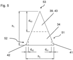
Figure 5 is a cross-sectional view of the of the separate helix element of the screw offigure 1 , near the tip of the screw. -
Figures 1 to 5 illustrate an embodiment of a concrete screw. The screw comprises anelongate shaft 10, which has atip end 11. Thetip end 11 is the leading end of theshaft 10 and theshaft 10 is intended to be inserted with thetip end 11 first into a borehole when the screw is installed. Theshaft 10 also hasrear end 18, which is located on theshaft 10 opposite thetip end 11. The screw furthermore has ascrew drive 19 that is provided on theshaft 10, for applying torque to theshaft 10. In the shown embodiment, thescrew drive 19 is a hex head located at therear end 18, and monolithically connected to theshaft 10, but this is an example only. Any other type ofscrew drive 19 can be used, such as an external type, for example hex, line (ALH), square, or a socket head, for example Bristol, clutch, double hex, hex socket, hexalobular socket, line (ALR), polydrive, Robertson, spline, TP3, and others. Thescrew drive 19 could also be located within theshaft 10 and/or remote from therear end 18, in particular if the screw is headless and/or internally threaded. - The
elongate shaft 10 comprises alongitudinal axis 99, extending in the longitudinal direction of theshaft 10 and through both thetip end 11 and through therear end 18. - The screw furthermore comprises a separate helix element 37, which is located on the
shaft 10, and which winds around theshaft 10 and/or thelongitudinal axis 99. In particular, the separate helix element 37 is arranged coaxially with respect to theshaft 10. The separate helix element 37 comprises a crest 39 and aroot 34. In particular, the crest 39 is helical and radially adjoins theroot 34, which is also helical. Theroot 34 is located on the radial inside of the separate helix element 37, i.e. it is located closer to thelongitudinal axis 99 of theshaft 10 than is the adjacent crest 39. - The separate helix element 37, in particular the crest 39 thereof, constitutes at least a helical section of a
screw thread 30 of the screw. In the shown embodiment, the separate helix element 37, in particular the crest 39 thereof, constitutes all of thescrew thread 30 of the screw, but this is an example only, and thescrew thread 30 might have additional helical sections. Thescrew thread 30 is located on theshaft 10, winds around theshaft 10 and/or thelongitudinal axis 99, and projects radially, with respect to thelongitudinal axis 99, from theshaft 10. Thescrew thread 30 is an external screw thread. - The separate helix element 37 and the
shaft 10 are non-monolithic with respect to one another. Due to the latter, thescrew thread 30 and theshaft 10 are also non-monolithic with respect to one another, at least regionally. - The
shaft 10 consists of a first material. The separate helix element 37 consists of a second material. In the present embodiment, the first material and the second material are different materials. The first material can in particular be a metal material, preferably a steel material, most preferably a stainless steel. The second material can in particular be a metal material, preferably a steel material, most preferably a stainless steel. Theshaft 10 and/or the separate helix element 37 could also be provided with a respective coating, comprising one or more layers. - In the present embodiment, the separate helix element 37 and/or the
screw thread 30 has a plurality of turns, namely approximately 7,5 turns. Preferably, at least two turns are provided. - Whereas in the shown embodiment, no additional screw threads are shown, the screw might also have additional screw threads, formed monolithically or non-monolithically with respect to the
shaft 10. - The screw is a concrete screw, i.e. the
screw thread 30 is able to tap, in particular cut, a corresponding mating thread in a concrete substrate. In particular, the crest 39 of the separate helix element 37 is able to cut into a concrete substrate and/or to form a positive interlock with the concrete substrate. Thescrew thread 30 has an outer thread diameter. At least near thetip end 11 of the non-installed screw, a ratio of the maximum outer thread diameter of thescrew thread 30 to the pitch of thescrew thread 30 is between 1 and 2, in particular between 1,2 and 1,6. - The
screw thread 30 might be strictly mathematically helical, but might also deviate from a helical form, which can e.g. provide additional functionality. - The
shaft 10 is provided with ahelical groove 80, which winds around thelongitudinal axis 99 of theshaft 10, and which projects, on the lateral surface of theshaft 10, radially into theshaft 10. The separate helix element 37, in particular theroot 34 thereof, is arranged within thegroove 80, whereas its crest 39 projects from theshaft 10. - The
shaft 10 is provided with a firstlateral embossment 81 and a secondlateral embossment 82, wherein both thefirst embossment 81 and thesecond embossment 82 secure the separate helix element 37 on theshaft 10, in particular they secure the separate helix element 37, in particular itsroot 34, within thegroove 80 in a claw-like manner. Both thefirst embossment 81 and thesecond embossment 82 have both axial (with respect to the longitudinal axis 99) overlap and radial (with respect to the longitudinal axis 99) overlap with the adjacent separate helix element 37, in particular with theroot 34 thereof. Both thefirst embossment 81 and thesecond embossment 82 clamp the separate helix element 37, in particular theroot 34 thereof, against theshaft 10. In particular, they clamp the separate helix element 37, in particular theroot 34 thereof, in the radial and axial directions (with respect to the longitudinal axis 99). - The
second embossment 82 projects forwardly, i.e. tipwardly, i.e. towards thetip end 11, whereas thefirst embossment 81 projects rearwardly, i.e. towards therear end 18, in particular headwardly. Thesecond embossment 82 clamps a rearwardly facing flank of the separate helix element 37, whereas thefirst embossment 81 clamps a forwardly facing, i.e. tipwardly facing, flank of the separate helix element 37. - In the present embodiment, the
first embossment 81 and thesecond embossment 82 extend all along the separate helix element 37, i.e. both thefirst embossment 81 and thesecond embossment 82 have the same number of turns as the separate helix element 37 has, wherein thefirst embossment 81 and thesecond embossment 82 subduct near thetip end 11. But this is an example only. - Both the
first embossment 81 and thesecond embossment 82 face, and preferably adjoin, the separate helix element 37. Both thefirst embossment 81 and thesecond embossment 82 adjoin thegroove 80, and thefirst embossment 81 delimits thegroove 80 rearwardly, and thesecond embossment 82 delimits the groove forwardly (i.e. tipwardly), i.e. thefirst embossment 81 forms a forwardly facing (i.e. tipwardly facing) flank of thegroove 80, and thesecond embossment 82 forms a rearwardly facing flank of thegroove 80. Thefirst embossment 81 and thesecond embossment 82 form an undercut structure at thegroove 80, and the groove is thus an undercutgroove 80. In the present embodiment, the undercut structure of thegroove 80 extends all along the separate helix element 37, but this is an example only. Thefirst embossment 81, thesecond embossment 82 and the undercutgroove 80 are shown to be continuous, but could also be provided with discontinuities, e.g. voids. The undercut structure of thegroove 80 secures the separate helix element 37, in particular theroot 34 thereof, on theshaft 10. The bottom of thegroove 80 is formed by theshaft 10, in particular by the lateral surface thereof. - Preferably, the
first embossment 81 and thesecond embossment 82 form the primary connection between the separate helix element 37 and theshaft 10. An additional material connection (for example gluing, or material connections based on heat input, such as brazing or welding) could also be provided, but are preferably absent. - The
first embossment 81 and thesecond embossment 82 radially project over the adjacent lateral surface of theshaft 10, i.e. they each form a raised shoulder that radially projects from theshaft 10. - The separate helix element 37 has generally triangular cross-section, namely that of an isosceles triangle, wherein the two sides of equal length are provided by the forwardly facing flank and the rearwardly facing flank of the separate helix element 37, respectively.
- A
crest serration 53 comprising a plurality of crest serration recesses 43, each having length l43, is provided in the separate helix element 37, namely in the crest 39, at a crest vertex edge of the separate helix element 37. Afirst root serration 51 comprising a plurality of first root serration recesses 41, each having length l41, is provided in the separate helix element 37, namely in theroot 34, at a (forwardly facing) first root vertex edge of the separate helix element 37. Asecond root serration 52 comprising a plurality of secondroot serration recess 42, each having length l42, is provided in the separate helix element 37, namely in theroot 34, at a (rearwardly facing) second root vertex edge of the separate helix element 37. Thefirst embossment 81 of theshaft 10 engages thefirst root serration 51, whereas thesecond embossment 82 engages thesecond root serration 52. - The crest serration recesses 43 are, when regarded along the separate helix element 37, longer than the root serration recesses 42 and 43. In particular, the following holds:
- ∘

- ∘

- In particular, the root serration recesses 42 and 43 are symmetrical about the vertical centroid of the profile of the separate helix element 37.
- As indicated in
figure 5 , the following holds for the depth d41 of the first root serration recesses 41 and the depth d42 of the second root serration recesses 42 (wherein depth can be in particular considered perpendicular to the centroid): -

-

- Wherein h2 is the width of the
root 34. - And the following holds for the depth d43 of the crest serration recesses 43
-

-

- Wherein h1 is the heigh of the separate helix element 37 in the radial direction.
- When the concrete screw is installed, a borehole is drilled in a concrete substrate according to the nominal diameter of the concrete screw. A baseplate that is to be attached might be present during drilling or might be positioned relatively to the borehole later. The drilled borehole has smaller diameter than the outer diameter of the
screw thread 30 of the concrete screw. This allows the concrete screw to engage the concrete with an undercutting at thescrew thread 30 when the concrete screw is subsequently screwed into the borehole, e.g. with an impact wrench.
Claims (11)
- Concrete screw comprising- a shaft (10),- at least one screw thread (30), which is arranged on the shaft (10), winds around the shaft (10) and protrudes from the shaft (10), and- a separate helix element (37), which is arranged non-monolithically on the shaft (10), wherein the separate helix element (37) winds around the shaft (10), protrudes from the shaft (10), and constitutes at least a section of the at least one screw thread (30),- wherein the separate helix element (37) comprises a crest (39) and a root (34), and- wherein the root (34) is provided with a first root serration (51) that is engaged, at least partly, by the shaft (10),characterized in that- the crest (39) is provided with a crest serration (53).
- Screw according to claim 1,
characterized in that
the separate helix element (37) has, at least regionally, generally triangular cross section, wherein the first root serration (51) is arranged at a first edge of the separate helix element (37), and wherein the crest serration (53) is arranged at a third edge of the separate helix element (37). - Screw according to claim 2,
characterized in that
the separate helix element (37) has, at least regionally, generally isosceles triangular cross section. - Screw according to any of the preceding claims,
characterized in that
the root (34) is provided with a second root serration (52) that is engaged, at least partly, by the shaft (10). - Screw according to claim 4 in connection with any of the claims 2 or 3,
characterized in that
the second root serration (52) is arranged at a second edge of the separate helix element (37). - Screw according to any of the preceding claims,characterized in thatthe first root serration (51) comprises at least one first root serration recess (41) having length l41, andthe crest serration (53) comprises at least one crest serration recess (43) having length l43,wherein the following holds:∘

- Screw according to any of the preceding claims,
characterized in that
the shaft (10) comprises a first embossment (81) that engages the first root serration (51). - Screw according to any of the proceeding claims,
characterized in that
the shaft (10) consists of a first material and the separate helix element (37) consists of a second material, wherein the first material and the second material are different materials. - Screw according to claim 8,
characterized in that
both the first material and the second material are metals, in particular stainless steels. - Screw according to any of the proceeding claims,
characterized in that
a ratio of the maximum outer thread diameter of the screw thread (30) to the pitch of the screw thread (30) is between 1 and 2, in particular between 1,2 and 1,6, at least in some regions of the screw thread (30). - Method for manufacturing a screw according to any of the preceding claims,
characterized in that
at least some of the first root serration recesses (41) of the first root serration (51) and/or at least some of the crest serration recesses (43) of the crest serration (53) are formed by means of a cutting process, preferably by means of laser cutting process.
Priority Applications (3)
| Application Number | Priority Date | Filing Date | Title |
|---|---|---|---|
| EP23175608.1A EP4467823A1 (en) | 2023-05-26 | 2023-05-26 | Screw comprising root and crest serrations |
| PCT/EP2024/063020 WO2024245720A1 (en) | 2023-05-26 | 2024-05-13 | Screw comprising root and crest serrations |
| EP24725861.9A EP4720531A1 (en) | 2023-05-26 | 2024-05-13 | Screw comprising root and crest serrations |
Applications Claiming Priority (1)
| Application Number | Priority Date | Filing Date | Title |
|---|---|---|---|
| EP23175608.1A EP4467823A1 (en) | 2023-05-26 | 2023-05-26 | Screw comprising root and crest serrations |
Publications (1)
| Publication Number | Publication Date |
|---|---|
| EP4467823A1 true EP4467823A1 (en) | 2024-11-27 |
Family
ID=86604950
Family Applications (2)
| Application Number | Title | Priority Date | Filing Date |
|---|---|---|---|
| EP23175608.1A Withdrawn EP4467823A1 (en) | 2023-05-26 | 2023-05-26 | Screw comprising root and crest serrations |
| EP24725861.9A Pending EP4720531A1 (en) | 2023-05-26 | 2024-05-13 | Screw comprising root and crest serrations |
Family Applications After (1)
| Application Number | Title | Priority Date | Filing Date |
|---|---|---|---|
| EP24725861.9A Pending EP4720531A1 (en) | 2023-05-26 | 2024-05-13 | Screw comprising root and crest serrations |
Country Status (2)
| Country | Link |
|---|---|
| EP (2) | EP4467823A1 (en) |
| WO (1) | WO2024245720A1 (en) |
Citations (9)
| Publication number | Priority date | Publication date | Assignee | Title |
|---|---|---|---|---|
| WO2011005379A1 (en) * | 2009-07-06 | 2011-01-13 | Illinois Tool Works Inc. | Threaded concrete anchor |
| EP2501944B1 (en) | 2009-11-18 | 2014-10-22 | Simpson Strong-Tie Company, Inc. | Fastener with hardened threads |
| EP2980424A1 (en) | 2014-07-31 | 2016-02-03 | King Point Enterprise Co., Ltd | Fastening bolt for use in concrete |
| US20160223006A1 (en) * | 2013-09-11 | 2016-08-04 | Ludwig Hettich Holding Gmbh & Co. Kg | Coil for a Threaded Insert |
| US20190240753A1 (en) * | 2016-10-14 | 2019-08-08 | Liberty Performance Steels Limited | Method and apparatus for producing toothed blades |
| EP3380737B1 (en) | 2015-11-26 | 2021-05-05 | fischerwerke GmbH & Co. KG | Concrete screw |
| EP3916246A1 (en) | 2020-05-28 | 2021-12-01 | Hilti Aktiengesellschaft | Separate screw thread helix fixed by means of claws |
| WO2021239518A1 (en) * | 2020-05-28 | 2021-12-02 | Hilti Aktiengesellschaft | Screw with separate thread helix and integral thread start |
| WO2022231920A1 (en) | 2021-04-30 | 2022-11-03 | Simpson Strong-Tie Company Inc. | Concrete fastener |
-
2023
- 2023-05-26 EP EP23175608.1A patent/EP4467823A1/en not_active Withdrawn
-
2024
- 2024-05-13 WO PCT/EP2024/063020 patent/WO2024245720A1/en not_active Ceased
- 2024-05-13 EP EP24725861.9A patent/EP4720531A1/en active Pending
Patent Citations (9)
| Publication number | Priority date | Publication date | Assignee | Title |
|---|---|---|---|---|
| WO2011005379A1 (en) * | 2009-07-06 | 2011-01-13 | Illinois Tool Works Inc. | Threaded concrete anchor |
| EP2501944B1 (en) | 2009-11-18 | 2014-10-22 | Simpson Strong-Tie Company, Inc. | Fastener with hardened threads |
| US20160223006A1 (en) * | 2013-09-11 | 2016-08-04 | Ludwig Hettich Holding Gmbh & Co. Kg | Coil for a Threaded Insert |
| EP2980424A1 (en) | 2014-07-31 | 2016-02-03 | King Point Enterprise Co., Ltd | Fastening bolt for use in concrete |
| EP3380737B1 (en) | 2015-11-26 | 2021-05-05 | fischerwerke GmbH & Co. KG | Concrete screw |
| US20190240753A1 (en) * | 2016-10-14 | 2019-08-08 | Liberty Performance Steels Limited | Method and apparatus for producing toothed blades |
| EP3916246A1 (en) | 2020-05-28 | 2021-12-01 | Hilti Aktiengesellschaft | Separate screw thread helix fixed by means of claws |
| WO2021239518A1 (en) * | 2020-05-28 | 2021-12-02 | Hilti Aktiengesellschaft | Screw with separate thread helix and integral thread start |
| WO2022231920A1 (en) | 2021-04-30 | 2022-11-03 | Simpson Strong-Tie Company Inc. | Concrete fastener |
Also Published As
| Publication number | Publication date |
|---|---|
| EP4720531A1 (en) | 2026-04-08 |
| WO2024245720A1 (en) | 2024-12-05 |
Similar Documents
| Publication | Publication Date | Title |
|---|---|---|
| EP4158208B1 (en) | Separate screw thread helix fixed by means of claws | |
| AU2016334696B2 (en) | Thread-forming screw with separate thread spiral and different part flank angles | |
| AU2017323389B2 (en) | A coupling device, associated parts and a method of use thereof | |
| EP4158209B1 (en) | Screw with separate thread helix and integral thread start | |
| US8920093B2 (en) | Thread-furrowing screw | |
| AU2020363401B2 (en) | Thread forming and thread locking fastener | |
| US11111943B2 (en) | Grooved nut for blind fastening, rivet and assembly comprising such a nut | |
| US6599072B1 (en) | Corrosion resisting screw with cutting insert | |
| MXPA05001729A (en) | Tapping assist fastening element and method. | |
| US20170266794A1 (en) | Drive Element for Transmitting a Torque to a Threaded Insert Sleeve | |
| EP1403537A1 (en) | Shaft with spline and stress relief groove and manufacturing method thereof | |
| WO2024245720A1 (en) | Screw comprising root and crest serrations | |
| EP4686842A1 (en) | Self-drilling self-tapping fastener | |
| EP4215765A1 (en) | Screw with subducting screw thread element | |
| JPH08177837A (en) | High strength torque type blind bolt with anti-rotation device | |
| AU2024329162A1 (en) | Concrete fastener |
Legal Events
| Date | Code | Title | Description |
|---|---|---|---|
| PUAI | Public reference made under article 153(3) epc to a published international application that has entered the european phase |
Free format text: ORIGINAL CODE: 0009012 |
|
| STAA | Information on the status of an ep patent application or granted ep patent |
Free format text: STATUS: THE APPLICATION HAS BEEN PUBLISHED |
|
| AK | Designated contracting states |
Kind code of ref document: A1 Designated state(s): AL AT BE BG CH CY CZ DE DK EE ES FI FR GB GR HR HU IE IS IT LI LT LU LV MC ME MK MT NL NO PL PT RO RS SE SI SK SM TR |
|
| STAA | Information on the status of an ep patent application or granted ep patent |
Free format text: STATUS: THE APPLICATION IS DEEMED TO BE WITHDRAWN |
|
| 18D | Application deemed to be withdrawn |
Effective date: 20250528 |