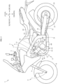
Technical Field
-
The present invention relates to an engine control method.
Prior Art
-
Japanese Unexamined Patent Publication S61-55323 A discloses a vehicle. A vehicle includes an engine, a first fuel injection device, and a second fuel injection device. The engine includes a first cylinder and a second cylinder. The first fuel injection device supplies fuel to the first cylinder. The second fuel injection device supplies fuel to the second cylinder. As the fuel burns in the first cylinder and the second cylinder, the engine rotates, and the engine outputs torque.
-
A vehicle includes a fuel cut control device. The fuel cut control device controls the first fuel injection device and the second fuel injection device on the basis of the rotation speed of the engine. Specifically, the fuel cut control device executes a first step, a second step, and a third step.
-
When the rotation speed of the engine is equal to or less than the first reference value, the first step is executed. In the first step, the fuel cut control device does not cut the fuel supply to the first cylinder and does not cut the fuel supply to the second cylinder. That is, in the first step, the fuel cut control device supplies fuel to the first cylinder and supplies fuel to the second cylinder.
-
When the rotation speed of the engine is larger than the first reference value and equal to or less than the second reference value, the second step is executed. In the second step, the fuel cut control device cuts the fuel supply to the first cylinder and does not cut the fuel supply to the second cylinder. That is, in the second step, the fuel cut control device stops to supply fuel to the first cylinder and supplies fuel to the second cylinder. Therefore, in the second step, it is difficult to increase the rotation speed of the engine.
-
When the rotation speed of the engine is larger than the second reference value, the third step is executed. In the third step, the fuel cut control device cuts the fuel supply to the first cylinder and cuts the fuel supply to the second cylinder. That is, in the third step, the fuel cut control device stops to supply fuel to the first cylinder and stops to supply fuel to the second cylinder. Therefore, in the third step, it is more difficult to increase the rotation speed of the engine.
-
In summary, the fuel cut control device includes the second step and the third step. Therefore, the rotation speed of the engine is less likely to be excessively high. That is, the fuel cut control device prevents over speed of the engine.
-
In the fuel cut control device of
Japanese Unexamined Patent Publication S61-55323 A , a difference between the amount of fuel supplied to the first cylinder in the first step and the amount of fuel supplied to the first cylinder in the second step is large. Therefore, when the step proceeds from the first step to the second step, the torque of the engine changes drastically.
-
In the fuel cut control device of
Japanese Unexamined Patent Publication S61-55323 A , a decrease amount of the fuel supplied to the first cylinder is large when the step proceeds from the first step to the second step. Therefore, when the step proceeds from the first step to the second step, the amount of decrease in the torque of the engine is large.
-
For the same reason, when the step proceeds from the second step to the third step, the torque of the engine changes drastically. When the step proceeds from the second step to the third step, the amount of decrease in the torque of the engine is large.
-
When the change in the torque of the engine is drastic, the change in the behavior of the vehicle is drastic. For example, when the amount of decrease in the torque of the engine is large, the vehicle decelerates significantly.
-
When the change in the behavior of the vehicle is drastic, the drivability of the vehicle tends to deteriorate. When the change in the behavior of the vehicle is drastic, the ride comfort of the driver tends to deteriorate.
-
The present invention has been made in view of such circumstances, and an object thereof is to provide an engine control method for preventing over speed of an engine while mitigating a change in torque of the engine.
Description of the Invention
-
In order to achieve such an object, the present invention has the following configuration.
-
That is, the present invention provides an engine control method for controlling an engine including a first cylinder and a second cylinder, the engine control method including:
- a first step of controlling a first amount that is an amount of fuel supplied to the first cylinder so that a first air-fuel ratio that is an air-fuel ratio of an air-fuel mixture supplied to the first cylinder is leaner than a theoretical air-fuel ratio and controlling a second amount that is an amount of fuel supplied to the second cylinder so that a second air-fuel ratio that is an air-fuel ratio of an air-fuel mixture supplied to the second cylinder is leaner than the theoretical air-fuel ratio when a rotation speed of the engine is equal to or more than a first reference value and less than a second reference value that is larger than the first reference value;
- a second step of controlling the first amount to zero and controlling the second amount so that the second air-fuel ratio is leaner than the theoretical air-fuel ratio when the rotation speed of the engine is equal to or more than the second reference value and less than a third reference value that is larger than the second reference value; and
- a third step of controlling the first amount to zero and controlling the second amount to zero when the rotation speed of the engine is equal to or more than the third reference value.
-
The engine control method is for controlling an engine. The engine includes a first cylinder and a second cylinder. The engine control method includes a first step, a second step, and a third step. When the rotation speed of the engine is equal to or more than the first reference value and less than the second reference value, the first step is executed. When the rotation speed of the engine is equal to or more than the second reference value and less than the third reference value, the second step is executed. When the rotation speed of the engine is equal to or more than the third reference value, the third step is executed. The second reference value is larger than the first reference value. The third reference value is larger than the second reference value.
-
In the first step, the second step, and the third step, the first amount and the second amount are controlled. The first amount is the amount of fuel supplied to the first cylinder. The second amount is the amount of fuel supplied to the second cylinder.
-
In the first step, the first amount is controlled so that the first air-fuel ratio is leaner than the theoretical air-fuel ratio. The first air-fuel ratio is an air-fuel ratio of an air-fuel mixture supplied to the first cylinder. Therefore, the first amount of the first step is relatively small. The first amount in the first step is larger than zero. In the first step, the second amount is controlled so that the second air-fuel ratio is leaner than the theoretical air-fuel ratio. The second air-fuel ratio is an air-fuel ratio of the air-fuel mixture supplied to the second cylinder. Therefore, the second amount in the first step is relatively small. The second amount in the first step is larger than zero.
-
In the second step, the first amount is controlled to zero. Therefore, the first amount of the second step is zero. In the second step, the supply of fuel to the first cylinder is stopped. In the second step, the second amount is controlled so that the second air-fuel ratio is leaner than the theoretical air-fuel ratio. Therefore, the second amount in the second step is relatively small. The second amount in the second step is larger than zero.
-
In the third step, the first amount is controlled to zero. Therefore, the first amount of the third step is zero. In the third step, the supply of fuel to the first cylinder is stopped. In the third step, the second amount is controlled to zero. Therefore, the second amount of the third step is zero. In the third step, the supply of fuel to the second cylinder is stopped.
-
As described above, the first amount in the first step is relatively small. The second amount in the first step is relatively small. Therefore, in the first step, it is slightly difficult to increase the rotation speed of the engine.
-
As described above, the first amount in the second step is zero. The second amount in the second step is relatively small. Therefore, in the second step, it is difficult to increase the rotation speed of the engine.
-
As described above, the first amount in the third step is zero. The second amount of the third step is zero. Therefore, in the third step, it is more difficult to increase the rotation speed of the engine.
-
As described above, the first amount in the first step is relatively small. The first amount of the second step is zero. Therefore, when the step proceeds from the first step to the second step, the first amount decreases. The difference between the first amount in the first step and the first amount in the second step is relatively small. When the step proceeds from the first step to the second step, the decrease amount of the first amount is relatively small. As described above, the second amount in the first step is relatively small. The second amount in the second step is relatively small. Therefore, the difference between the second amount in the first step and the second amount in the second step is very small. When the step proceeds from the first step to the second step, the decrease amount of the second amount is very small. Therefore, when the step proceeds from the first step to the second step, the change in the torque of the engine is moderate. When the step proceeds from the first step to the second step, the amount of decrease in the torque of the engine is small.
-
As described above, the first amount in the second step is zero. The first amount of the third step is zero. Therefore, there is no difference between the first amount in the second step and the first amount in the third step. When the step proceeds from the second step to the third step, the first amount does not increase or decrease. When the step proceeds from the second step to the third step, the decrease amount of the first amount is zero. As described above, the second amount in the second step is relatively small. The second amount of the third step is zero. Therefore, when the step proceeds from the second step to the third step, the second amount decreases. The difference between the second amount in the second step and the second amount in the third step is relatively small. When the step proceeds from the second step to the third step, the decrease amount of the second amount is relatively small. Therefore, when the step proceeds from the second step to the third step, the change in the torque of the engine is moderate. When the step proceeds from the second step to the third step, the amount of decrease in the torque of the engine is small.
-
In summary, in the engine control method, the first amount and the second amount gradually decrease as the rotation speed of the engine increases. In other words, as the rotation speed of the engine increases, the engine control method gradually cuts off the first amount and the second amount. Therefore, the engine control method prevents over speed of the engine while mitigating a change in torque of the engine. The engine control method prevents an excessive increase in the rotation speed of the engine while mitigating a change in the torque of the engine.
-
It is preferred in the above-described engine control method that,
- in the first step, the first amount is controlled so that the first air-fuel ratio is 16 or more and 20 or less, and the second amount is controlled so that the second air-fuel ratio is 16 or more and 20 or less, and
- in the second step, the second amount is controlled so that the second air-fuel ratio is 16 or more and 20 or less.
-
In the first step, the first amount is controlled so that the first air-fuel ratio is 16 or more and 20 or less. Therefore, it is easy to make the first air-fuel ratio of the first step leaner than the theoretical air-fuel ratio.
-
In the first step, the first amount is controlled so that the first air-fuel ratio is 16 or more and 20 or less. Therefore, the first amount in the first step is smaller. Therefore, the difference between the first amount in the first step and the first amount in the second step is smaller. When the step proceeds from the first step to the second step, the decrease amount of the first amount is smaller. Therefore, when the step proceeds from the first step to the second step, the change in the torque of the engine is more moderate. When the step proceeds from the first step to the second step, the amount of decrease in the torque of the engine is smaller.
-
In the first step, the second amount is controlled so that the second air-fuel ratio is 16 or more and 20 or less. Therefore, it is easy to make the second air-fuel ratio of the first step leaner than the theoretical air-fuel ratio.
-
In the second step, the second amount is controlled so that the second air-fuel ratio is 16 or more and 20 or less. Therefore, it is easy to make the second air-fuel ratio of the second step leaner than the theoretical air-fuel ratio.
-
In the second step, the second amount is controlled so that the second air-fuel ratio is 16 or more and 20 or less. Therefore, the second amount in the second step is smaller. Therefore, the difference between the second amount in the second step and the second amount in the third step is relatively small. When the step proceeds from the second step to the third step, the decrease amount of the second amount is smaller. Therefore, when the step proceeds from the second step to the third step, the change in the torque of the engine is more moderate. When the step proceeds from the second step to the third step, the amount of decrease in the torque of the engine is smaller.
-
It is preferred in the above-described engine control method that,
- the engine control method further comprises a fourth step for controlling the first amount and the second amount when the rotation speed of the engine is equal to or more than a fourth reference value that is smaller than the first reference value, and less than the first reference value, and
- in the fourth step, the first amount is controlled so that the first air-fuel ratio in the fourth step is richer than the first air-fuel ratio in the first step, and the second amount is controlled so that the second air-fuel ratio in the fourth step is richer than the second air-fuel ratio in the first step.
-
The engine control method includes a fourth step. When the rotation speed of the engine is equal to or more than the fourth reference value and less than the first reference value, the fourth step is executed. The fourth reference value is smaller than the first reference value. In the fourth step, the first amount and the second amount are controlled.
-
In the fourth step, the first amount is controlled so that the first air-fuel ratio of the fourth step is richer than the first air-fuel ratio of the first step. Therefore, the first amount of the fourth step is relatively large. In the fourth step, the second amount is controlled so that the second air-fuel ratio of the fourth step is richer than the second air-fuel ratio of the first step. Therefore, the second amount of the fourth step is relatively large.
-
As described above, the first amount in the first step is larger than zero. Therefore, the difference between the first amount in the fourth step and the first amount in the first step is relatively small. As described above, the second amount in the first step is larger than zero. Therefore, the difference between the second amount in the fourth step and the second amount in the first step is relatively small. Therefore, when the step proceeds from the fourth step to the first step, the change in the torque of the engine is moderate.
-
It is preferred in the above-described engine control method that,
in the fourth step, the first amount is controlled so that the first air-fuel ratio is less than 16, and the second amount is controlled so that the second air-fuel ratio is less than 16.
-
Therefore, it is easy to make the first air-fuel ratio of the fourth step richer than the first air-fuel ratio of the first step. It is easy to make the second air-fuel ratio of the fourth step richer than the second air-fuel ratio of the first step.
-
It is preferred in the above-described engine control method that,
in the fourth step, the first amount is controlled so that the first air-fuel ratio is 15 or less, and the second amount is controlled so that the second air-fuel ratio is 15 or less.
-
Therefore, it is easier to make the first air-fuel ratio of the fourth step richer than the first air-fuel ratio of the first step. It is easier to make the second air-fuel ratio of the fourth step richer than the second air-fuel ratio of the first step.
-
It is preferred in the above-described engine control method that,
in the fourth step, the first amount is controlled so that the first air-fuel ratio is 13 or less, and the second amount is controlled so that the second air-fuel ratio is 13 or less.
-
Therefore, it is easier to make the first air-fuel ratio of the fourth step richer than the first air-fuel ratio of the first step. It is easier to make the second air-fuel ratio of the fourth step richer than the second air-fuel ratio of the first step.
-
It is preferred in the above-described engine control method that,
in the fourth step, the first amount is controlled so that the first air-fuel ratio is 12 or less, and the second amount is controlled so that the second air-fuel ratio is 12 or less.
-
Therefore, it is easier to make the first air-fuel ratio of the fourth step richer than the first air-fuel ratio of the first step. It is easier to make the second air-fuel ratio of the fourth step richer than the second air-fuel ratio of the first step.
-
It is preferred in the above-described engine control method that,
the first amount decreases and the second amount decreases when the step proceeds from the fourth step to the first step.
-
When the step proceeds from the fourth step to the first step, the first amount decreases. As described above, the difference between the first amount in the fourth step and the first amount in the first step is relatively small. Therefore, when the step proceeds from the fourth step to the first step, the decrease amount of the first amount is relatively small. When the step proceeds from the fourth step to the first step, the second amount decreases. As described above, the difference between the second amount in the fourth step and the second amount in the first step is relatively small. Therefore, when the step proceeds from the fourth step to the first step, the decrease amount of the second amount is relatively small. Therefore, when the step proceeds from the fourth step to the first step, the amount of decrease in the torque of the engine is small.
-
As described above, when the step proceeds from the fourth step to the first step, the first amount decreases. Therefore, in the first step, it is easy to make the first air-fuel ratio leaner than the theoretical air-fuel ratio.
-
As described above, when the step proceeds from the fourth step to the first step, the second amount decreases. Therefore, in the first step, it is easy to make the second air-fuel ratio leaner than the theoretical air-fuel ratio.
-
It is preferred in the above-described engine control method that,
in the fourth step, the first amount is controlled so that the first air-fuel ratio is 5 or more, and the second amount is controlled so that the second air-fuel ratio is 5 or more.
-
In the fourth step, the first amount is controlled so that the first air-fuel ratio is 5 or more. Therefore, the first amount of the fourth step is not excessively large. The difference between the first amount in the fourth step and the first amount in the first step is not excessively large. When the step proceeds from the fourth step to the first step, the decrease amount of the first amount is not excessively large. In the fourth step, the second amount is controlled so that the second air-fuel ratio is 5 or more. Therefore, the second amount of the fourth step is not excessively large. The difference between the second amount in the fourth step and the second amount in the first step is not excessively large. When the step proceeds from the fourth step to the first step, the decrease amount of the second amount is not excessively large. Therefore, when the step proceeds from the fourth step to the first step, the change in the torque of the engine is not excessively drastic. When the step proceeds from the fourth step to the first step, the amount of decrease in the torque of the engine is not excessively large.
-
It is preferred in the above-described engine control method that,
- the first amount in the first step is 70% or more and 90% or less of the first amount in the fourth step, and
- the second amount in the first step is 70% or more and 90% or less of the second amount in the fourth step.
-
Therefore, when the step proceeds from the fourth step to the first step, it is easy to reduce the first amount. When the step proceeds from the fourth step to the first step, it is easy to reduce the second amount.
-
It is preferred in the above-described engine control method that,
a difference between the fourth reference value and the first reference value is 100 rpm or less.
-
As described above, the range of the rotation speed at which the fourth step is executed may be narrow.
-
It is preferred in the above-described engine control method that,
in the first step, the second air-fuel ratio is equal to the first air-fuel ratio.
-
Therefore, in the first step, the control of the second air-fuel ratio is common to the control of the first air-fuel ratio. Therefore, the control of the first step is simple.
-
It is preferred in the above-described engine control method that,
in the first step, the second amount is equal to the first amount.
-
Therefore, in the first step, it is easy to make the second air-fuel ratio equal to the first air-fuel ratio.
-
It is preferred in the above-described engine control method that,
the first reference value is 7,000 rpm or more.
-
Therefore, when the rotation speed of the engine is 7,000 rpm or more, the first step is started. In other words, when the rotation speed of the engine is less than 7,000 rpm, the first step is not executed. When the rotation speed of the engine is less than 7,000 rpm, also the second step is not executed. When the rotation speed of the engine is less than 7,000 rpm, also the third step is not executed. Therefore, when the rotation speed of the engine is less than 7,000 rpm, the engine control method does not cut the first amount. When the rotation speed of the engine is less than 7,000 rpm, the engine control method does not cut the second amount. Therefore, when the rotation speed of the engine is less than 7,000 rpm, the engine control method does not change the torque of the engine. When the rotation speed of the engine is less than 7,000 rpm, the engine control method does not intervene.
-
It is preferred in the above-described engine control method that,
the first reference value is 8,000 rpm or more.
-
Therefore, when the rotation speed of the engine is less than 8,000 rpm, the engine control method does not change the torque of the engine.
-
It is preferred in the above-described engine control method that,
the first reference value is 9,000 rpm or more.
-
Therefore, when the rotation speed of the engine is less than 9,000 rpm, the engine control method does not change the torque of the engine.
-
It is preferred in the above-described engine control method that,
a difference between the second reference value and the first reference value is smaller than a difference between the third reference value and the second reference value.
-
The difference between the second reference value and the first reference value corresponds to a range of the rotation speed of the engine in which the first step is executed. The difference between the third reference value and the second reference value corresponds to a range of the rotation speed of the engine in which the second step is executed. Therefore, the range of the rotation speed of the engine in which the first step is executed is narrower than the range of the rotation speed of the engine in which the second step is executed. Therefore, the period of the first step is relatively short. Therefore, it is easy to quickly shift the step from the first step to the second step. As a result, it is easy to quickly prevent over speed of the engine.
-
It is preferred in the above-described engine control method that,
a difference between the third reference value and the second reference value is equal to or more than twice of a difference between the second reference value and the first reference value.
-
Therefore, it is easy to make the difference between the second reference value and the first reference value smaller than the difference between the third reference value and the second reference value.
-
It is preferred in the above-described engine control method that,
a difference between the second reference value and the first reference value is 200 rpm or less.
-
Therefore, it is easy to make the difference between the second reference value and the first reference value smaller than the difference between the third reference value and the second reference value.
-
It is preferred in the above-described engine control method that,
a difference between the third reference value and the second reference value is 100 rpm or more.
-
Therefore, it is easy to make the difference between the second reference value and the first reference value smaller than the difference between the third reference value and the second reference value.
-
It is preferred in the above-described engine control method that,
a difference between the third reference value and the second reference value is 200 rpm or more.
-
Therefore, it is easier to make the difference between the second reference value and the first reference value smaller than the difference between the third reference value and the second reference value.
-
It is preferred in the above-described engine control method that
a difference between the third reference value and the second reference value is 500 rpm or less.
-
Therefore, the difference between the third reference value and the second reference value is not excessively wide. Therefore, the period of the second step is not excessively long. Therefore, the second step proceeds to the third step at an appropriate timing. As a result, it is easy to properly prevent over speed of the engine.
-
It is preferred in the above-described engine control method that,
- the first amount is controlled by controlling a first fuel injection device provided in a first intake portion communicating with the first cylinder, and
- the second amount is controlled by controlling a second fuel injection device provided in a second intake portion communicating with the second cylinder.
-
The first intake portion communicates with the first cylinder. The first fuel injection device is provided in the first intake portion. The first amount is controlled by controlling the first fuel injection device. Here, the first fuel injection device supplies fuel to the first cylinder through the first intake portion. Therefore, it is easy to control the first amount. Similarly, the second intake portion communicates with the second cylinder. The second fuel injection device is provided in the second intake portion. The second amount is controlled by controlling the second fuel injection device. Here, the second fuel injection device supplies fuel to the second cylinder through the second intake portion. Therefore, it is easy to control the second amount.
-
It is preferred in the above-described engine control method that,
- the first amount is controlled by controlling a fuel injection time of the first fuel injection device, and
- the second amount is controlled by controlling a fuel injection time of the second fuel injection device.
-
Therefore, it is easier to control the first amount. It is easier to control the second amount.
-
It is preferred in the above-described engine control method that,
the engine is mounted on a straddled vehicle.
-
When the change in the torque of the engine is moderate, the change in the behavior of the straddled vehicle is moderate. For example, when the amount of decrease in the torque of the engine is small, the straddled vehicle decelerates gently. When the change in the behavior of the straddled vehicle is moderate, the drivability of the straddled vehicle is unlikely to deteriorate. When the change in the behavior of the straddled vehicle is moderate, the ride comfort of the driver is unlikely to deteriorate.
Brief Description of the Drawings
-
For the purpose of illustrating the invention, there are shown in the drawings several forms which are presently preferred, it being understood, however, that the invention is not limited to the precise arrangement and instrumentalities shown.
- Fig. 1 is a left side view of a straddled vehicle according to an embodiment.
- Fig. 2 is a conceptual diagram schematically illustrating a part of the straddled vehicle.
- Fig. 3 is a graph schematically illustrating an engine control method.
Embodiments of the invention
-
A straddled vehicle 1 according to this invention will be described hereinafter with reference to the drawings.
1. Outline Construction of Straddled Vehicle 1
-
Fig. 1 is a left side view of a straddled vehicle 1 according to an embodiment. The straddled vehicle 1 is classified as a street-type vehicle, for example.
-
Fig. 1 shows a longitudinal direction X, a transverse direction Y, and an up-down direction Z of the straddled vehicle 1. The longitudinal direction X, transverse direction Y, and up-down direction Z are defined with reference to a driver (also called a rider) riding the straddled vehicle 1. The longitudinal direction X, transverse direction Y, and up-down direction Z are perpendicular to one another. The longitudinal direction X and transverse direction Y are horizontal. The up-down direction Z is vertical.
-
The terms "forward", "rearward", "upward", "downward", "rightward", and "leftward", respectively, mean "forward", "rearward", "upward", "downward", "rightward", and "leftward" as seen from the driver mounted on the straddled vehicle 1. Unless otherwise stated in this specification, "forward" and "rearward" include not only directions parallel to the longitudinal direction X but also directions close to the longitudinal direction X. The directions close to the longitudinal direction X are, for example, directions at angles not exceeding 45 degrees to the longitudinal direction X. Similarly, unless otherwise specified, "rightward" and "leftward" include not only directions parallel to the transverse direction Y but also directions close to the transverse direction Y. Unless otherwise specified, "upward" and "downward" include not only directions parallel to the up-down direction Z but also directions close to the up-down direction Z. For reference, the drawings show the terms FRONT, REAR, UP and DOWN, as appropriate.
-
In the present specification, "in side view of the straddled vehicle 1" is appropriately referred to as "in vehicle side view".
-
The straddled vehicle 1 includes a vehicle body frame 2. The vehicle body frame 2 includes a main frame 3. The main frame 3 extends rearward from the front part of the straddled vehicle 1. More specifically, the main frame 3 extends rearward and downward.
-
The straddled vehicle 1 includes a steering device 4 and a front wheel 8. The steering device 4 is provided at the front part of the straddled vehicle 1. The steering device 4 is supported by the vehicle body frame 2. The steering device 4 is rotatable with respect to the vehicle body frame 2. The front wheel 8 is supported by the steering device 4.
-
The steering device 4 includes a handlebar 5, a front suspension 6, and a front axle 7. The handlebar 5 includes, for example, an accelerator operator (not illustrated). The accelerator operator is, for example, an accelerator grip. The front suspension 6 extends downward from the handlebar 5. The front axle 7 is supported by a lower portion of the front suspension 6. The front wheel 8 is supported by the front axle 7. The front wheel 8 is rotatable about the front axle 7.
-
The straddled vehicle 1 includes a fuel tank 9. The fuel tank 9 is disposed above the main frame 3 in vehicle side view. The fuel tank 9 is disposed behind the steering device 4. The fuel tank 9 stores fuel.
-
The straddled vehicle 1 includes a seat 10. The seat 10 is disposed above the main frame 3 in vehicle side view. The seat 10 is disposed behind the fuel tank 9. The entire of the seat 10 is disposed lower than the upper end of the fuel tank 9. A part of the seat 10 is disposed at the same height position as the fuel tank 9.
-
The straddled vehicle 1 includes an engine 11. At least a part of the engine 11 is disposed below the main frame 3 in vehicle side view. The engine 11 is disposed behind the steering device 4. The engine 11 is disposed below the fuel tank 9 and the seat 10. The engine 11 rotates and produces torque by burning fuel.
-
The engine 11 is mounted on the straddled vehicle 1. The engine 11 is supported by the vehicle body frame 2. For example, the engine 11 is supported by the main frame 3. The engine 11 is rigidly supported by the vehicle body frame 2. The engine 11 is fixed to the vehicle body frame 2. The engine 11 is not swingable with respect to the vehicle body frame 2. The engine 11 is not rotatable with respect to the vehicle body frame 2. The engine 11 is classified as a rigid mount engine.
-
The straddled vehicle 1 includes a pivot shaft 21, a swing arm 22, a rear axle 23, and a rear wheel 24. The pivot shaft 21 is disposed below the fuel tank 9 and the seat 10. The pivot shaft 21 is disposed behind the engine 11. The pivot shaft 21 is supported by the vehicle body frame 2. The swing arm 22 is supported by the pivot shaft 21. The swing arm 22 is swingable about the pivot shaft 21. The swing arm 22 extends rearward from the pivot shaft 21. The rear axle 23 is supported by the rear part of the swing arm 22. The rear wheel 24 is supported by the rear axle 23. The rear wheel 24 is rotatable about the rear axle 23.
-
The straddled vehicle 1 includes a chain 25. The chain 25 couples the engine 11 and the rear wheel 24. The chain 25 transmits torque from the engine 11 to the rear wheel 24. The engine 11 drives the rear wheels 24 via the chain 25. Specifically, the engine 11 rotates the rear wheel 24 about the rear axle 23.
-
A driver of the straddled vehicle 1 sits astride the seat 10 and performs a knee grip. The knee grip is to sandwich a part of the straddled vehicle 1 between both legs of the driver. The part of the straddled vehicle 1 is, for example, at least a part of the main frame 3 and the fuel tank 9. The driver grips the handlebar 5 and steers the steering device 4. The driver operates the accelerator operator provided on the handlebar 5.
2. Details of engine 11 and configuration related to engine 11
-
Refer to Fig. 1. The engine 11 includes a crankcase 12 and a cylinder unit 13. The cylinder unit 13 is provided above the crankcase 12.
-
Refer to Figs. 1 and 2. Fig. 2 is a conceptual diagram schematically illustrating a part of the straddled vehicle 1.
-
The engine 11 is classified as a multi-cylinder engine. For example, the engine 11 is classified as a two-cylinder engine.
-
The engine 11 includes a first cylinder 15a and a second cylinder 15b. Each of the first cylinder 15a and the second cylinder 15b is a space. Each of the first cylinder 15a and the second cylinder 15b is located in the engine 11. Each of the first cylinder 15a and the second cylinder 15b is located in the cylinder unit 13.
-
The engine 11 includes a first piston 16a and a second piston 16b. The first piston 16a is disposed in the first cylinder 15a. The first piston 16a moves in the first cylinder 15a. The second piston 16b is located in the second cylinder 15b. The second piston 16b moves in the second cylinder 15b.
-
The first cylinder 15a and the first piston 16a define a first combustion chamber. The first combustion chamber is a part of the first cylinder 15a. The second cylinder 15b and the second piston 16b define a second combustion chamber. The second combustion chamber is a part of the second cylinder 15b.
-
The engine 11 includes a crankshaft 17. The crankshaft 17 is installed in the engine 11. The crankshaft 17 is installed in the crankcase 12. The crankshaft 17 is coupled to the first piston 16a and the second piston 16b.
-
The engine 11 includes a first intake port 18a and a second intake port 18b. Each of the first intake port 18a and the second intake port 18b is a space. Each of the first intake port 18a and the second intake port 18b is located in the engine 11. Each of the first intake port 18a and the second intake port 18b is located in the cylinder unit 13. The first intake port 18a communicates with the first cylinder 15a. The first intake port 18a sends air to the first cylinder 15a. The second intake port 18b communicates with the second cylinder 15b. The second intake port 18b sends air to the second cylinder 15b.
-
The engine 11 includes a first intake valve and a second intake valve (not illustrated). The first intake valve is provided in the first intake port 18a. The first intake valve opens and closes the first intake port 18a. When the first intake valve opens the first intake port 18a, the first cylinder 15a communicates with the first intake port 18a. When the first intake valve opens the first intake port 18a, the first intake valve allows the first cylinder 15a to take in air from the first intake port 18a. When the first intake valve closes the first intake port 18a, the first cylinder 15a is blocked from the first intake port 18a. When the first intake valve closes the first intake port 18a, the first intake valve prohibits the first cylinder 15a from taking in air from the first intake port 18a. The second intake valve is provided in the second intake port 18b. The second intake valve opens and closes the second intake port 18b.
-
The engine 11 includes a first exhaust port 19a and a second exhaust port 19b. Each of the first exhaust port 19a and the second exhaust port 19b is a space. The first exhaust port 19a and the second exhaust port 19b are located inside the engine 11. Each of the first exhaust port 19a and the second exhaust port 19b is located inside the cylinder unit 13. The first exhaust port 19a communicates with the first cylinder 15a. The first cylinder 15a discharges exhaust gas to the first exhaust port 19a. The second exhaust port 19b communicates with the second cylinder 15b. The second cylinder 15b discharges exhaust gas to the second exhaust port 19b.
-
The engine 11 includes a first exhaust valve and a second exhaust valve (not illustrated). The first exhaust valve is provided in the first exhaust port 19a. The first exhaust valve opens and closes the first exhaust port 19a. When the first exhaust valve opens the first exhaust port 19a, the first cylinder 15a communicates with the first exhaust port 19a. When the first exhaust valve opens the first exhaust port 19a, the first exhaust valve allows the first cylinder 15a to discharge the exhaust gas to the first exhaust port 19a. When the first exhaust valve closes the first exhaust port 19a, the first cylinder 15a is blocked from the first exhaust port 19a. When the first exhaust valve closes the first exhaust port 19a, the first exhaust valve prohibits the first cylinder 15a from discharging the exhaust gas to the first exhaust port 19a. The second exhaust valve is provided in the second exhaust port 19b. The second exhaust valve opens and closes the second exhaust port 19b.
-
The straddled vehicle 1 includes an intake pipe 31. The intake pipe 31 is connected to the engine 11. The intake pipe 31 supplies air to the engine 11.
-
Specifically, the intake pipe 31 is connected to the cylinder unit 13.
-
More specifically, the intake pipe 31 is connected to the first intake port 18a and the second intake port 18b. The intake pipe 31 communicates with the first intake port 18a and the second intake port 18b. The intake pipe 31 communicates with the first cylinder 15a and the second cylinder 15b through the first intake port 18a and the second intake port 18b. The intake pipe 31 supplies air to the first intake port 18a and the second intake port 18b. The intake pipe 31 supplies air to the first cylinder 15a and the second cylinder 15b through the first intake port 18a and the second intake port 18b.
-
For example, the intake pipe 31 includes a first intake portion 32a and a second intake portion 32b. The first intake portion 32a is connected to the first intake port 18a. The first intake portion 32a communicates with the first intake port 18a. The first intake portion 32a communicates with the first cylinder 15a through the first intake port 18a. The first intake portion 32a supplies air to the first intake port 18a. The first intake portion 32a supplies air to the first cylinder 15a through the first intake port 18a. The second intake portion 32b is connected to the second intake port 18b. The second intake portion 32b communicates with the second intake port 18b. The second intake portion 32b communicates with the second cylinder 15b through the second intake port 18b. The second intake portion 32b supplies air to the second intake port 18b. The second intake portion 32b supplies air to the second cylinder 15b through the second intake port 18b.
-
For example, the intake pipe 31 includes a collective intake portion 33. The collective intake portion 33 is connected to the first intake portion 32a and the second intake portion 32b. The collective intake portion 33 collects the first intake portion 32a and the second intake portion 32b. In other words, the first intake portion 32a and the second intake portion 32b branch from the collective intake portion 33. The collective intake portion 33 supplies air to the first intake portion 32a and the second intake portion 32b.
-
The straddled vehicle 1 includes an air cleaner 34. The air cleaner 34 is connected to the intake pipe 31. The air cleaner 34 supplies air to the intake pipe 31.
-
For example, the air cleaner 34 is connected to the collective intake portion 33. The air cleaner 34 supplies air to the collective intake portion 33.
-
The straddled vehicle 1 includes a throttle 35. The throttle 35 is provided in the intake pipe 31. The throttle 35 opens and closes the intake pipe 31. The throttle 35 adjusts the amount of air flowing through the intake pipe 31.
-
The amount of air flowing through the intake pipe 31 corresponds to the amount of intake air of the engine 11. Therefore, the throttle 35 adjusts an intake amount of the engine 11.
-
The amount of air flowing through the intake pipe 31 corresponds to the intake amount of the first cylinder 15a and the second cylinder 15b. Therefore, the throttle 35 adjusts the intake amount of the first cylinder 15a and the second cylinder 15b.
-
The throttle 35 is operated in accordance with the operation of the accelerator operator by the driver.
-
For example, the throttle 35 is classified as a mechanical throttle. The straddled vehicle 1 includes a coupling member (not illustrated). The coupling member mechanically couples the accelerator operator and the throttle 35. The coupling member includes, for example, at least one of a wire, a cable, and a linkage mechanism.
-
For example, the throttle 35 includes a first throttle 36a and a second throttle 36b. The first throttle 36a is provided in the first intake portion 32a. The first throttle 36a opens and closes the first intake portion 32a. The first throttle 36a adjusts the amount of air flowing through the first intake portion 32a. The second throttle 36b is provided in the second intake portion 32b. The second throttle 36b opens and closes the second intake portion 32b. The second throttle 36b adjusts the amount of air flowing through the second intake portion 32b.
-
The amount of air flowing through the first intake portion 32a corresponds to the intake amount of the first cylinder 15a. Therefore, the first throttle 36a adjusts the intake amount of the first cylinder 15a. The amount of air flowing through the second intake portion 32b corresponds to the intake amount of the second cylinder 15b. Therefore, the second throttle 36b adjusts the intake amount of the second cylinder 15b.
-
The first throttle 36a includes, for example, a throttle valve. The second throttle 36b includes, for example, a throttle valve.
-
For example, the first throttle 36a and the second throttle 36b are coupled to each other. The throttle valve of the first throttle 36a and the throttle valve of the second throttle 36b are fixed to a common valve shaft.
-
For example, the first throttle 36a and the second throttle 36b operate integrally. The first throttle 36a and the second throttle 36b are integrally opened and closed. Therefore, the position of the second throttle 36b is equal to the position of the first throttle 36a. The opening degree of the second throttle 36b is equal to the opening degree of the first throttle 36a. Therefore, the intake amount of the second cylinder 15b is substantially equal to the intake amount of the first cylinder 15a.
-
The straddled vehicle 1 includes a fuel injection device 37. The fuel tank 9 supplies fuel to the fuel injection device 37. The fuel injection device 37 supplies fuel to the engine 11.
-
For example, the fuel injection device 37 is provided in the intake pipe 31. The fuel injection device 37 injects fuel into the intake pipe 31. The intake pipe 31 sends fuel to the engine 11. The fuel injection device 37 supplies fuel to the engine 11 through the intake pipe 31.
-
More specifically, the intake pipe 31 sends fuel to the first intake port 18a and the second intake port 18b. For example, the first intake portion 32a sends fuel to the first intake port 18a. The second intake portion 32b sends fuel to the second intake port 18b. The first intake port 18a sends fuel to the first cylinder 15a. The second intake port 18b sends fuel to the second cylinder 15b. The fuel injection device 37 supplies fuel to the first cylinder 15a and the second cylinder 15b through the intake pipe 31, the first intake port 18a, and the second intake port 18b.
-
For example, the fuel injection device 37 is disposed downstream of the throttle 35 in the air flow direction. The fuel injection device 37 is provided in a portion of the intake pipe 31 located between the engine 11 and the throttle 35.
-
For example, the fuel injection device 37 includes a first fuel injection device 38a and a second fuel injection device 38b. The first fuel injection device 38a is provided in the first intake portion 32a. The first fuel injection device 38a injects fuel into the first intake portion 32a. The first fuel injection device 38a supplies fuel to the first cylinder 15a through the first intake portion 32a and the first intake port 18a. The second fuel injection device 38b is provided in the second intake portion 32b. The second fuel injection device 38b injects fuel into the second intake portion 32b. The second fuel injection device 38b supplies fuel to the second cylinder 15b through the second intake portion 32b and the second intake port 18b.
-
For example, the first fuel injection device 38a is disposed downstream of the first throttle 36a in the air flow direction. The first fuel injection device 38a is provided in a portion of the first intake portion 32a located between the engine 11 and the first throttle 36a. The second fuel injection device 38b is disposed downstream of the second throttle 36b in the air flow direction. The second fuel injection device 38b is provided in a portion of the second intake portion 32b located between the engine 11 and the second throttle 36b.
-
When fuel is injected, the air becomes a fuel-containing mixture. Therefore, when the fuel is supplied to the first cylinder 15a, the air-fuel mixture is supplied to the first cylinder 15a. When fuel is not supplied to the first cylinder 15a, only air is supplied to the first cylinder 15a. When the fuel is supplied to the second cylinder 15b, the air-fuel mixture is supplied to the second cylinder 15b. When fuel is not supplied to the second cylinder 15b, only air is supplied to the second cylinder 15b.
-
The straddled vehicle 1 includes an ignition device 41. The ignition device 41 is attached to the engine 11. The ignition device 41 ignites the air-fuel mixture in the engine 11. The air-fuel mixture burns in the engine 11.
-
For example, the ignition device 41 is attached to the cylinder unit 13.
-
The ignition device 41 ignites the air-fuel mixture in the first cylinder 15a and the second cylinder 15b. The air-fuel mixture burns in the first cylinder 15a and the second cylinder 15b.
-
For example, the ignition device 41 includes a first ignition device 42a and a second ignition device 42b. The first ignition device 42a ignites the air-fuel mixture in the first cylinder 15a. The air-fuel mixture burns in the first cylinder 15a. The second ignition device 41b ignites the air-fuel mixture in the second cylinder 15b. The air-fuel mixture burns in the second cylinder 15b.
-
The first ignition device 42a is provided in the first cylinder 15a. The first ignition device 42a extends to the first cylinder 15a. The second ignition device 42b is provided in the second cylinder 15b. The second ignition device 42b extends to the second cylinder 15b.
-
The first ignition device 42a includes, for example, an ignition plug. The second ignition device 42b includes, for example, an ignition plug.
-
The combustion of the air-fuel mixture in the first cylinder 15a causes the first piston 16a to reciprocate in the first cylinder 15a. The combustion of the air-fuel mixture in the second cylinder 15b causes the second piston 16b to reciprocate in the second cylinder 15b. The first piston 16a and the second piston 16b drive the crankshaft 17. When the first piston 16a and the second piston 16b reciprocate, the crankshaft 17 rotates.
-
In short, the combustion of the air-fuel mixture rotates the crankshaft 17. The combustion of the air-fuel mixture rotates the engine 11. Combustion of the air-fuel mixture causes the engine 11 to produce torque.
-
The air-fuel mixture burns and becomes exhaust gas. For example, the exhaust gas is generated in the first cylinder 15a by combustion of the air-fuel mixture in the first cylinder 15a. Exhaust gas is generated in the second cylinder 15b by combustion of the air-fuel mixture in the second cylinder 15b.
-
The straddled vehicle 1 includes an exhaust pipe 45. The exhaust pipe 45 is connected to the engine 11. The engine 11 discharges exhaust gas to the exhaust pipe 45. The exhaust pipe 45 conveys exhaust gas.
-
The exhaust pipe 45 is connected to the cylinder unit 13.
-
The exhaust pipe 45 is connected to the first exhaust port 19a and the second exhaust port 19b. The exhaust pipe 45 communicates with the first exhaust port 19a and the second exhaust port 19b. The exhaust pipe 45 communicates with the first cylinder 15a and the second cylinder 15b through the first exhaust port 19a and the second exhaust port 19b. The first exhaust port 19a sends exhaust gas to the exhaust pipe 45. The second exhaust port 19b sends the exhaust gas to the exhaust pipe 45. The first cylinder 15a and the second cylinder 15b discharge exhaust gas to the exhaust pipe 45 through the first exhaust port 19a and the second exhaust port 19b.
-
For example, the exhaust pipe 45 includes a first exhaust portion 46a and a second exhaust portion 46b. The first exhaust portion 46a is connected to the first exhaust port 19a. The first exhaust portion 46a communicates with the first exhaust port 19a. The first exhaust portion 46a communicates with the first cylinder 15a through the first exhaust port 19a. The first cylinder 15a discharges exhaust gas to the first exhaust portion 46a through the first exhaust port 19a. The second exhaust portion 46b is connected to the second exhaust port 19b. The second exhaust portion 46b communicates with the second exhaust port 19b. The second exhaust portion 46b communicates with the second cylinder 15b through the second exhaust port 19b. The second cylinder 15b discharges the exhaust gas to the second exhaust portion 46b through the second exhaust port 19b.
-
For example, the exhaust pipe 45 includes a collective exhaust portion 47. The collective exhaust portion 47 is connected to the first exhaust portion 46a and the second exhaust portion 46b. The collective exhaust portion 47 collects the first exhaust portion 46a and the second exhaust portion 46b. The first exhaust portion 46a sends the exhaust gas to the collective exhaust portion 47. The second exhaust portion 46b sends the exhaust gas to the collective exhaust portion 47.
-
The straddled vehicle 1 includes a catalyst 48. The catalyst 48 is provided in the exhaust pipe 45. The exhaust gas passes through the catalyst 48. The catalyst 48 purifies the exhaust gas.
-
For example, the catalyst 48 is provided in the collective exhaust portion 47.
-
For example, the catalyst 48 is a three-way catalyst.
-
After the catalyst 48 purifies the exhaust gas, the exhaust pipe 45 releases the exhaust gas. The exhaust pipe 45 releases the exhaust gas to the outside of the straddled vehicle 1.
-
For example, the collective exhaust portion 47 releases exhaust gas.
-
The straddled vehicle 1 includes a rotation speed sensor 51. The rotation speed sensor 51 is attached to the engine 11. The rotation speed sensor 51 detects the rotation speed of the engine 11.
-
The rotation speed sensor 51 is attached to, for example, the crankcase 12. The rotation speed sensor 51 is attached to, for example, the crankshaft 17. The rotation speed sensor 51 detects, for example, the rotation speed of the crankshaft 17.
-
The straddled vehicle 1 includes a throttle sensor 52. The throttle sensor 52 is attached to the throttle 35. The throttle sensor 52 is attached to, for example, a valve shaft. The throttle sensor 52 detects the amount of air flowing through the intake pipe 31.
-
For example, the throttle sensor 52 detects a throttle position. The throttle position is a position of the throttle 35. For example, the throttle position is an opening degree of the throttle 35.
-
The straddled vehicle 1 includes an air-fuel ratio sensor 53. The air-fuel ratio sensor 53 detects the air-fuel ratio of the air-fuel mixture.
-
The air-fuel ratio of the air-fuel mixture is a mass ratio of air and fuel in the air-fuel mixture. The air-fuel ratio of the air-fuel mixture is a value obtained by dividing the mass of air in the air-fuel mixture by the mass of fuel in the air-fuel mixture.
-
More specifically, the air-fuel ratio sensor 53 detects the air-fuel ratio of the air-fuel mixture supplied to the first cylinder 15a and the second cylinder 15b. The air-fuel ratio sensor 53 detects the air-fuel ratio of the air-fuel mixture before combustion.
-
For example, the air-fuel ratio sensor 53 is provided in the exhaust pipe 45. The air-fuel ratio sensor 53 detects the concentration of oxygen in the exhaust gas. The concentration of oxygen in the exhaust gas is an index indicating the air-fuel ratio of the air-fuel mixture. The air-fuel ratio of the air-fuel mixture is specified on the basis of the concentration of oxygen in the exhaust gas.
-
For example, the air-fuel ratio sensor 53 is disposed upstream of the catalyst 48 in the direction in which the exhaust gas flows. The air-fuel ratio sensor 53 is provided in a portion of the exhaust pipe 45 located between the engine 11 and the catalyst 48. The air-fuel ratio sensor 53 is provided in the collective exhaust portion 47.
-
The straddled vehicle 1 includes a controller 61. The controller 61 includes, for example, a read-only memory (ROM), a processor, and a random-access memory (RAM). The ROM stores various programs. The program stored in the ROM includes, for example, an engine control program. The processor performs arithmetic processing. The processor executes the program stored in the ROM. As a result, the processor realizes various functions. The processor is, for example, a central processing unit (CPU). The RAM temporarily stores various types of information. The RAM is used as a work area of the processor.
-
The controller 61 includes a storage 62. The storage 62 may include a part of the ROM and the RAM described above. The storage 62 may include components other than the ROM and the RAM described above. The storage 62 may be at least one of a semiconductor memory and a hard disk.
-
The controller 61 may be an electric control unit (ECU) provided in the straddled vehicle 1.
-
The controller 61 controls the engine 11.
-
The controller 61 is electrically connected to the fuel injection device 37, the ignition device 41, the rotation speed sensor 51, the throttle sensor 52, and the air-fuel ratio sensor 53. The controller 61 communicates with the fuel injection device 37, the ignition device 41, the rotation speed sensor 51, the throttle sensor 52, and the air-fuel ratio sensor 53.
-
The controller 61 controls the fuel injection device 37. The fuel injection device 37 operates according to the control of the controller 61.
-
The controller 61 controls the first fuel injection device 38a and the second fuel injection device 38b. The first fuel injection device 38a and the second fuel injection device 38b operate under the control of the controller 61.
-
The controller 61 controls a first amount Q1 and a second amount Q2. The first amount Q1 is an amount of fuel supplied to the first cylinder 15a. The second amount Q2 is an amount of fuel supplied to the second cylinder 15b.
-
For example, the first amount Q1 corresponds to the amount of fuel injected by the first fuel injection device 38a. The second amount Q2 corresponds to the amount of fuel injected by the second fuel injection device 38b. Therefore, the controller 61 controls the first amount Q1 by controlling the first fuel injection device 38a. The controller 61 controls the second amount Q2 by controlling the second fuel injection device 38b.
-
The first amount Q1 depends on, for example, the fuel injection time of the first fuel injection device 38a. The second amount Q2 depends on, for example, the fuel injection time of the second fuel injection device 38b. Therefore, the controller 61 controls the first amount Q1 by controlling the fuel injection time of the first fuel injection device 38a. The controller 61 controls the second amount Q2 by controlling the fuel injection time of the second fuel injection device 38b.
-
The controller 61 controls the ignition device 41. The ignition device 41 operates according to the control of the controller 61.
-
The rotation speed sensor 51 outputs a detection result of the rotation speed sensor 51 to the controller 61. The controller 61 acquires a detection result of the rotation speed sensor 51.
-
The throttle sensor 52 outputs a detection result of the throttle sensor 52 to the controller 61. The controller 61 acquires a detection result of the throttle sensor 52.
-
The air-fuel ratio sensor 53 outputs a detection result of the air-fuel ratio sensor 53 to the controller 61. The controller 61 acquires a detection result of the air-fuel ratio sensor 53.
-
The storage 62 stores the fuel amount condition information E. The fuel amount condition information E is information for determining the first amount Q1 and the second amount Q2. The fuel amount condition information E defines, for example, a relationship between the rotation speed A of the engine 11, the first amount Q1, and the second amount Q2.
3. Operation example of engine control method
-
An operation of the engine control method will be described. Fig. 3 is a graph schematically illustrating an engine control method. Fig. 3 illustrates a relationship among the rotation speed A of the engine 11, the first amount Q1, and the second amount Q2.
-
The controller 61 acquires the rotation speed A on the basis of the detection result of the rotation speed sensor 51. The rotation speed A is a rotation speed of the engine 11. Specifically, the rotation speed A is a measurement value of the rotation speed of the engine 11. The rotation speed A is measured by the rotation speed sensor 51. The unit of the rotation speed A is, for example, [rpm].
-
The controller 61 controls the first amount Q1 and the second amount Q2 on the basis of the rotation speed A. The controller 61 controls the first amount Q1 and the second amount Q2 on the basis of the rotation speed A and the fuel amount condition information E. As a result, the first amount Q1 changes according to the rotation speed A. The second amount Q2 changes according to the rotation speed A.
-
The engine control method is divided into a first step, a second step, a third step, and a fourth step according to the rotation speed A.
-
When the rotation speed A is equal to or more than the first reference value B 1 and less than the second reference value B2, the first step is executed. When the rotation speed A is equal to or more than the second reference value B2 and less than the third reference value B3, the second step is executed. When the rotation speed A is equal to or more than the third reference value B3, the third step is executed. When the rotation speed A is equal to or more than the fourth reference value B4 and less than the first reference value B1, the fourth step is executed.
-
In the first step, the controller 61 controls the first amount Q1 and the second amount Q2. In the second step, the controller 61 controls the first amount Q1 and the second amount Q2. In the third step, the controller 61 controls the first amount Q1 and the second amount Q2. In the fourth step, the controller 61 controls the first amount Q1 and the second amount Q2.
-
Each of the first to fourth reference values B1 to B4 is a reference value of the rotation speed A. Each of the first to fourth reference values B 1 to B4 is, for example, a constant.
-
For example, the first reference value B 1 is 7,000 rpm or more. For example, the first reference value B 1 is 8,000 rpm or more. For example, the first reference value B 1 is 9,000 rpm or more.
-
The second reference value B2 is larger than the first reference value B 1. The third reference value B3 is larger than the second reference value B2. The fourth reference value B4 is smaller than the first reference value B 1.
-
The difference between the second reference value B2 and the first reference value B 1 corresponds to a range of the rotation speed A in which the first step is executed. The difference between the second reference value B2 and the first reference value B 1 is referred to as a "difference C1".
-
The difference between the third reference value B3 and the second reference value B2 corresponds to the range of the rotation speed A in which the second step is executed. The difference between the third reference value B3 and the second reference value B2 is referred to as a "difference C2".
-
The difference between the fourth reference value B4 and the first reference value B1 corresponds to the range of the rotation speed A in which the fourth step is executed. The difference between the fourth reference value B4 and the first reference value B1 is referred to as a "difference C4".
-
For example, the difference C1 is smaller than the difference C2. For example, the difference C2 is equal to or more than twice of the difference C 1.
-
For example, the difference C1 is 200 rpm or less. For example, the difference C1 is 100 rpm or less.
-
For example, the difference C2 is 100 rpm or more. For example, the difference C2 is 200 rpm or more.
-
For example, the difference C2 is 500 rpm or less.
-
The difference C4 may be small. For example, the difference C4 is smaller than the difference C1. For example, the difference C4 is smaller than the difference C2. For example, the difference C4 is 100 rpm or less.
-
Alternatively, the difference C4 may be large. For example, the difference C4 is larger than the difference C1. For example, the difference C4 is larger than the difference C2. For example, the difference C4 is larger than 100 rpm.
-
For example, the fourth reference value B4 may be 0 rpm.
-
For example, the first reference value B1 is 9,450 rpm. The second reference value B2 is 9,600 rpm. The third reference value B3 is 10,000 rpm. The fourth reference value B4 is 9,400 rpm. The difference C1 is 150 rpm. The difference C2 is 400 rpm. The difference C4 is 50 rpm.
-
Hereinafter, the first step, the fourth step, the second step, and the third step will be described in this order.
-
The first step will be described. In the first step, the first amount Q1 is controlled so that the first air-fuel ratio D1 is leaner than a theoretical air-fuel ratio. In the first step, the second amount Q2 is controlled so that the second air-fuel ratio D2 is leaner than the theoretical air-fuel ratio.
-
The first air-fuel ratio D1 is an air-fuel ratio of an air-fuel mixture supplied to the first cylinder 15a. The second air-fuel ratio D2 is an air-fuel ratio of an air-fuel mixture supplied to the second cylinder 15b. When the fuel is gasoline, the theoretical air-fuel ratio is, for example, 14.7. "The first air-fuel ratio D1 is leaner than the theoretical air-fuel ratio" means, for example, that "the first air-fuel ratio D1 is larger than 14.7". "The second air-fuel ratio D2 is leaner than the theoretical air-fuel ratio" means, for example, that "the second air-fuel ratio D2 is larger than 14.7".
-
For example, in the first step, the first amount Q1 is controlled so that the first air-fuel ratio D1 is 16 or more and 20 or less. In the first step, the second amount Q2 is controlled so that the second air-fuel ratio D2 is 16 or more and 20 or less.
-
For example, in the first step, the first amount Q1 and the second amount Q2 are controlled so that the second air-fuel ratio D2 is equal to the first air-fuel ratio D1.
-
For example, in the first step, the first amount Q1 and the second amount Q2 are controlled so that the second amount Q2 is equal to the first amount Q1.
-
The first amount Q1 and the second amount Q2 of the first step are defined in the fuel amount condition information E.
-
As a result, the first amount Q1 of the first step is the first amount Q1b. The first amount Q1b is defined in the fuel amount condition information E. The first amount Q1b is defined in the fuel amount condition information E as the first amount Q1 of the first step. The first amount Q1b is larger than zero. In the first step, the first amount Q1b of fuel is supplied to the first cylinder 15a. For example, the fuel injection device 37 supplies the first amount Q1b of fuel to the first cylinder 15a. The first fuel injection device 38a injects the fuel of the first amount Q1b.
-
The second amount Q2 of the first step is the second amount Q2b. The second amount Q2b is defined in the fuel amount condition information E. The second amount Q2b is defined in the fuel amount condition information E as the second amount Q2 of the first step. The second amount Q2b is larger than zero. In the first step, the second amount Q2b of fuel is supplied to the second cylinder 15b. For example, the fuel injection device 37 supplies the second cylinder 15b with the second amount Q2b of fuel. The second fuel injection device 38b injects the fuel of the second amount Q2b.
-
For example, in the first step, the second amount Q2b is equal to the first amount Q1b. That is, the second amount Q2b of the first step is equal to the first amount Q1b of the first step.
-
Fig. 3 further illustrates the relationship among the rotation speed A of the engine 11, the first air-fuel ratio D1, and the second air-fuel ratio D2. As a result, the first air-fuel ratio D1 in the first step is the first air-fuel ratio D1b. That is, in the first step, the air-fuel mixture of the first air-fuel ratio D1b burns in the first cylinder 15a. The first air-fuel ratio D1b is leaner than the theoretical air-fuel ratio. The combustion of the air-fuel mixture having the first air-fuel ratio D1b is sometimes referred to as "lean burn".
-
The second air-fuel ratio D2 in the first step is the second air-fuel ratio D2b. That is, in the first step, the air-fuel mixture of the second air-fuel ratio D2b burns in the second cylinder 15b. The second air-fuel ratio D2b is leaner than the theoretical air-fuel ratio. The combustion of the air-fuel mixture having the second air-fuel ratio D2b is sometimes referred to as "lean burn".
-
For example, the first air-fuel ratio D1b is 16 or more and 20 or less. The second air-fuel ratio D2b is 16 or more and 20 or less.
-
For example, the second air-fuel ratio D2b is equal to the first air-fuel ratio D1b.
-
The fourth step will be described. In the fourth step, the first amount Q1 is controlled so that the first air-fuel ratio D1 of the fourth step is richer than the first air-fuel ratio D1b of the first step. In the fourth step, the second amount Q2 is controlled so that the second air-fuel ratio D2 in the fourth step is richer than the second air-fuel ratio D2b in the first step.
-
"The first air-fuel ratio D1 of the fourth step is richer than the first air-fuel ratio D1b of the first step" means that "the first air-fuel ratio D1 of the fourth step is smaller than the first air-fuel ratio D1b of the first step". "The second air-fuel ratio D2 of the fourth step is richer than the second air-fuel ratio D2b of the first step" means that "the second air-fuel ratio D2 of the fourth step is smaller than the second air-fuel ratio D2b of the first step".
-
For example, in the fourth step, the first amount Q1 is controlled so that the first air-fuel ratio D1 is less than 16. In the fourth step, the second amount Q2 is controlled so that the second air-fuel ratio D2 is less than 16.
-
For example, in the fourth step, the first amount Q1 is controlled so that the first air-fuel ratio D1 is 15 or less. In the fourth step, the second amount Q2 is controlled so that the second air-fuel ratio D2 is 15 or less.
-
For example, in the fourth step, the first amount Q1 is controlled so that the first air-fuel ratio D1 is 13 or less. In the fourth step, the second amount Q2 is controlled so that the second air-fuel ratio D2 is 13 or less.
-
For example, in the fourth step, the first amount Q1 is controlled so that the first air-fuel ratio D1 is 12 or less. In the fourth step, the second amount Q2 is controlled so that the second air-fuel ratio D2 is 12 or less.
-
For example, in the fourth step, the first amount Q1 is controlled so that the first air-fuel ratio D1 is 5 or more. In the fourth step, the second amount Q2 is controlled so that the second air-fuel ratio D2 is 5 or more.
-
For example, in the fourth step, the first amount Q1 is controlled so that the first air-fuel ratio D1 is 11.5. In the fourth step, the second amount Q2 is controlled so that the second air-fuel ratio D2 is 11.5.
-
For example, in the fourth step, the first amount Q1 is controlled so that the first air-fuel ratio D1 is an output air-fuel ratio. In the fourth step, the second amount Q2 is controlled so that the second air-fuel ratio D2 is the output air-fuel ratio.
-
The output air-fuel ratio is an air-fuel ratio that maximizes the output of the engine 11.
-
For example, in the fourth step, the first amount Q1 and the second amount Q2 are controlled so that the second air-fuel ratio D2 is equal to the first air-fuel ratio D1.
-
For example, in the fourth step, the first amount Q1 and the second amount Q2 are controlled so that the second amount Q2 is equal to the first amount Q1.
-
The first amount Q1 and the second amount Q2 of the fourth step are defined in the fuel amount condition information E.
-
As a result, the first amount Q1 of the fourth step is the first amount Q1a. The first amount Q1a is defined in the fuel amount condition information E. The first amount Q1a is defined in the fuel amount condition information E as the first amount Q1 of the fourth step. The first amount Q1a is larger than zero. In the fourth step, the fuel of the first amount Q1a is supplied to the first cylinder 15a.
-
The second amount Q2 of the fourth step is the second amount Q2a. The second amount Q2a is defined in the fuel amount condition information E. The second amount Q2a is defined in the fuel amount condition information E as the second amount Q2 of the fourth step. The second amount Q2a is larger than zero. In the fourth step, the fuel of the second amount Q2a is supplied to the second cylinder 15b.
-
For example, in the fourth step, the second amount Q2a is equal to the first amount Q1a.
-
For example, the first amount Q1a of the fourth step is larger than the first amount Q1b of the first step. Therefore, when the step proceeds from the first step to the fourth step, the first amount Q1 increases. On the contrary, when the step proceeds from the fourth step to the first step, the first amount Q1 decreases.
-
For example, the second amount Q2a in the fourth step is larger than the second amount Q2b in the first step. Therefore, when the step proceeds from the first step to the fourth step, the second amount Q2 increases. On the contrary, when the step proceeds from the fourth step to the first step, the second amount Q2 decreases.
-
For example, the first amount Q1b of the first step is 70% or more and 90% or less of the first amount Q1a of the fourth step.
-
For example, the second amount Q2b in the first step is 70% or more and 90% or less of the second amount Q2a in the fourth step.
-
As a result, the first air-fuel ratio D1 in the fourth step is the first air-fuel ratio D1a. That is, in the fourth step, the air-fuel mixture having the first air-fuel ratio D1a burns in the first cylinder 15a. The first air-fuel ratio D1a of the fourth step is richer than the first air-fuel ratio D1b of the first step. The first air-fuel ratio D1a of the fourth step is smaller than the first air-fuel ratio D1b of the first step.
-
The second air-fuel ratio D2 in the fourth step is the second air-fuel ratio D2a. That is, in the fourth step, the air-fuel mixture of the second air-fuel ratio D2a burns in the second cylinder 15b. The second air-fuel ratio D2a in the fourth step is richer than the second air-fuel ratio D2b in the first step. The second air-fuel ratio D2a in the fourth step is smaller than the second air-fuel ratio D2b in the first step.
-
For example, the first air-fuel ratio D1a is less than 16. The second air-fuel ratio D2a is less than 16.
-
For example, the first air-fuel ratio D1a is 15 or less. The second air-fuel ratio D2a is 15 or less.
-
For example, the first air-fuel ratio D1a is 13 or less. The second air-fuel ratio D2a is 13 or less.
-
For example, the first air-fuel ratio D1a is 12 or less. The second air-fuel ratio D2a is 12 or less.
-
For example, the first air-fuel ratio D1a is 5 or more. The second air-fuel ratio D2a is 5 or more.
-
For example, the first air-fuel ratio D1a is 11.5. The second air-fuel ratio D2a is 11.5.
-
For example, the first air-fuel ratio D1a is equal to the output air-fuel ratio. The second air-fuel ratio D2a is equal to the output air-fuel ratio.
-
For example, the second air-fuel ratio D2a is equal to the first air-fuel ratio D1a.
-
The second step will be described. In the second step, the first amount Q1 is controlled to zero. In the second step, the second amount Q2 is controlled so that the second air-fuel ratio D2 is leaner than the theoretical air-fuel ratio.
-
For example, in the second step, the second amount Q2 is controlled so that the second air-fuel ratio D2 is 16 or more and 20 or less.
-
The first amount Q1 and the second amount Q2 of the second step are defined in the fuel amount condition information E.
-
As a result, the first amount Q1 of the second step is the first amount Q1c. The first amount Q1c is defined in the fuel amount condition information E. The first amount Q1c is defined in the fuel amount condition information E as the first amount Q1 of the second step. The first amount Q1c is zero. In the second step, the supply of fuel to the first cylinder 15a is stopped. For example, the fuel injection device 37 does not supply fuel to the first cylinder 15a. The first fuel injection device 38a does not inject fuel.
-
The second amount Q2 of the second step is the second amount Q2b. The second amount Q2b is defined in the fuel amount condition information E. The second amount Q2b is defined in the fuel amount condition information E as the second amount Q2 of the second step. The second amount Q2b in the second step is larger than zero. In the second step, the second amount Q2b of fuel is supplied to the second cylinder 15b.
-
The first amount Q1c in the second step is smaller than the first amount Q1b in the first step. Therefore, when the step proceeds from the first step to the second step, the first amount Q1 decreases.
-
The first amount Q1c in the second step is smaller than the first amount Q1a in the fourth step.
-
A difference between the first amount Q1b of the first step and the first amount Q1c of the second step is smaller than a difference between the first amount Q1a of the fourth step and the first amount Q1c of the second step.
-
The second amount Q2b of the second step may be substantially equal to the second amount Q2b of the first step. When the step proceeds from the first step to the second step, the second amount Q2 may not decrease. Alternatively, the second amount Q2b of the second step may be smaller than the second amount Q2b of the first step. When the step proceeds from the first step to the second step, the second amount Q2 may decrease.
-
For example, the second amount Q2b of the second step is smaller than the second amount Q2a of the fourth step.
-
For example, the difference between the second amount Q2b of the first step and the second amount Q2b of the second step is smaller than the difference between the second amount Q2a of the fourth step and the second amount Q2b of the second step.
-
For example, the second amount Q2b in the second step is 70% or more and 90% or less of the second amount Q2a in the fourth step.
-
The second amount Q2b of the second step is more than the first amount Q1c of the second step.
-
As a result, in the second step, the air-fuel mixture is not supplied to the first cylinder 15a. In the second step, only air is supplied to the first cylinder 15a. In the second step, combustion does not occur in the first cylinder 15a. That is, in the second step, the first cylinder 15a is in the non-combustion state. In the second step, the first cylinder 15a is in an unburned state.
-
The second air-fuel ratio D2 in the second step is the second air-fuel ratio D2b. That is, in the second step, the air-fuel mixture of the second air-fuel ratio D2b burns in the second cylinder 15b. The second air-fuel ratio D2b in the second step is leaner than the theoretical air-fuel ratio.
-
For example, the second air-fuel ratio D2b in the second step is 16 or more and 20 or less.
-
The third step will be described. In the third step, the first amount Q1 is controlled to zero. In the third step, the second amount Q2 is controlled to zero.
-
The first amount Q1 and the second amount Q2 of the third step are defined in the fuel amount condition information E.
-
As a result, the first amount Q1 of the third step is the first amount Q1c. The first amount Q1c is defined in the fuel amount condition information E. The first amount Q1c is defined in the fuel amount condition information E as the first amount Q1 of the third step. The first amount Q1c is zero. In the third step, the supply of fuel to the first cylinder 15a is stopped.
-
The second amount Q2 of the third step is the second amount Q2c. The second amount Q2c is defined in the fuel amount condition information E. The second amount Q2c is defined in the fuel amount condition information E as the second amount Q2 of the third step. The second amount Q2c is zero. In the third step, the supply of fuel to the second cylinder 15b is stopped. For example, the fuel injection device 37 does not supply fuel to the second cylinder 15b. The second fuel injection device 38b does not inject fuel.
-
The first amount Q1c of the third step is equal to the first amount Q1c of the second step. When the step proceeds from the second step to the third step, the first amount Q1 does not increase or decrease.
-
The first amount Q1c in the third step is smaller than the first amount Q1b in the first step.
-
The first amount Q1c in the third step is smaller than the first amount Q1a in the fourth step.
-
A difference between the first amount Q1c of the second step and the first amount Q1c of the third step is smaller than a difference between the first amount Q1a of the fourth step and the first amount Q1c of the third step.
-
The second amount Q2c in the third step is smaller than the second amount Q2b in the second step. Therefore, when the step proceeds from the second step to the third step, the second amount Q2 decreases.
-
The second amount Q2c of the third step is smaller than the second amount Q2b of the first step.
-
The second amount Q2c of the third step is smaller than the second amount Q2a of the fourth step.
-
The difference between the second amount Q2b of the second step and the second amount Q2c of the third step is smaller than the difference between the second amount Q2a of the fourth steps and the second amount Q2c of the third step.
-
The second amount Q2c of the third step is equal to the first amount Q1c of the third step.
-
As a result, in the third step, the air-fuel mixture is not supplied to the first cylinder 15a. In the third step, only air is supplied to the first cylinder 15a. In the third step, combustion does not occur in the first cylinder 15a. That is, in the third step, the first cylinder 15a is in the non-combustion state. In the third step, the first cylinder 15a is in an unburned state.
-
In the third step, the air-fuel mixture is not supplied to the second cylinder 15b. In the third step, only air is supplied to the second cylinder 15b. In the third step, combustion does not occur in the second cylinder 15b. That is, in the third step, the second cylinder 15b is in the non-combustion state. In the third step, the second cylinder 15b is in an unburned state.
4. Effects of Embodiment
-
The engine control method is for controlling the engine 11. The engine 11 includes the first cylinder 15a and the second cylinder 15b. The engine control method includes the first step, the second step, and the third step. When the rotation speed A of the engine 11 is equal to or more than the first reference value B1 and less than the second reference value B2, the first step is executed. When the rotation speed A of the engine 11 is equal to or more than the second reference value B2 and less than the third reference value B3, the second step is executed. When the rotation speed A of the engine 11 is equal to or more than the third reference value B3, the third step is executed. The second reference value B2 is larger than the first reference value B1. The third reference value B3 is larger than the second reference value B2.
-
In the first step, the second step, and the third step, the first amount Q1 and the second amount Q2 are controlled. The first amount Q1 is the amount of fuel supplied to the first cylinder 15a. The second amount Q2 is the amount of fuel supplied to the second cylinder 15b.
-
In the first step, the first amount Q1 is controlled so that the first air-fuel ratio D1 is leaner than the theoretical air-fuel ratio. The first air-fuel ratio D1 is the air-fuel ratio of the air-fuel mixture supplied to the first cylinder 15a. Therefore, the first amount Q1b of the first step is relatively small. The first amount Q1b of the first step is larger than zero. In the first step, the second amount Q2 is controlled so that the second air-fuel ratio D2 is leaner than the theoretical air-fuel ratio. The second air-fuel ratio D2 is the air-fuel ratio of the air-fuel mixture supplied to the second cylinder 15b. Therefore, the second amount Q2b of the first step is relatively small. The second amount Q2b in the first step is larger than zero.
-
In the second step, the first amount Q1 is controlled to zero. Therefore, the first amount Q1c of the second step is zero. In the second step, the supply of fuel to the first cylinder 15a is stopped. In the second step, the second amount Q2 is controlled so that the second air-fuel ratio D2 is leaner than the theoretical air-fuel ratio. Therefore, the second amount Q2b of the second step is relatively small. The second amount Q2b in the second step is larger than zero.
-
In the third step, the first amount Q1 is controlled to zero. Therefore, the first amount Q1c of the third step is zero. In the third step, the supply of fuel to the first cylinder 15a is stopped. In the third step, the second amount Q2 is controlled to zero. Therefore, the second amount Q2c of the third step is zero. In the third step, the supply of fuel to the second cylinder 15b is stopped.
-
As described above, the first amount Q1b of the first step is relatively small. The second amount Q2b of the first step is relatively small. Therefore, in the first step, it is slightly difficult to increase the rotation speed A of the engine 11. In the first step, it is slightly easy to decrease the rotation speed A of the engine 11.
-
As described above, the first amount Q1c in the second step is zero. The second amount Q2b of the second step is relatively small. Therefore, in the second step, it is difficult to increase the rotation speed A of the engine 11. In the second step, it is easy to reduce the rotation speed A of the engine 11.
-
As described above, the first amount Q1c in the third step is zero. The second amount Q2c in the third step is zero. Therefore, in the third step, it is more difficult to increase the rotation speed A of the engine 11. In the third step, it is easier to decrease the rotation speed A of the engine 11.
-
As described above, the first amount Q1b of the first step is relatively small. The first amount Q1c in the second step is zero. Therefore, when the step proceeds from the first step to the second step, the first amount Q1 decreases. A difference between the first amount Q1b of the first step and the first amount Q1c of the second step is relatively small. When the step proceeds from the first step to the second step, the decrease amount of the first amount Q1 is relatively small. As described above, the second amount Q2b of the first step is relatively small. The second amount Q2b of the second step is relatively small. Therefore, the difference between the second amount Q2b of the first step and the second amount Q2b of the second step is very small. When the step proceeds from the first step to the second step, the decrease amount of the second amount Q2 is very small. Therefore, when the step proceeds from the first step to the second step, the change in the torque of the engine 11 is moderate. When the step proceeds from the first step to the second step, the amount of decrease in the torque of the engine 11 is small.
-
As described above, the first amount Q1c in the second step is zero. The first amount Q1c in the third step is zero. Therefore, there is no difference between the first amount Q1c of the second step and the first amount Q1c of the third step. When the step proceeds from the second step to the third step, the first amount Q1 does not increase or decrease. When the step proceeds from the second step to the third step, the decrease amount of the first amount Q1 is zero. As described above, the second amount Q2b of the second step is relatively small. The second amount Q2c in the third step is zero. Therefore, when the step proceeds from the second step to the third step, the second amount Q2 decreases. A difference between the second amount Q2b of the second step and the second amount Q2c of the third step is relatively small. When the step proceeds from the second step to the third step, the decrease amount of the second amount Q2 is relatively small. Therefore, when the step proceeds from the second step to the third step, the change in the torque of the engine 11 is moderate. When the step proceeds from the second step to the third step, the amount of decrease in the torque of the engine 11 is small.
-
In summary, in the engine control method, the first amount Q1 and the second amount Q2 gradually decrease as the rotation speed A of the engine 11 increases. In other words, as the rotation speed A of the engine 11 increases, the engine control method gently cuts off the first amount Q1 and the second amount Q2. Therefore, the engine control method prevents over speed of the engine 11 while mitigating a change in torque of the engine 11. The engine control method prevents an excessive increase in the rotation speed A of the engine 11 while mitigating a change in the torque of the engine 11.
-
When the change in the torque of the engine 11 is moderate, the change in the behavior of the straddled vehicle 1 is moderate. For example, when the amount of decrease in the torque of the engine 11 is small, the straddled vehicle 1 decelerates gently. When the change in the behavior of the straddled vehicle 1 is moderate, the drivability of the straddled vehicle 1 is unlikely to deteriorate. When the change in the behavior of the straddled vehicle 1 is moderate, the ride comfort of the driver of the straddled vehicle 1 is unlikely to deteriorate. Therefore, even when the step proceeds from the first step to the second step, the straddled vehicle 1 has excellent drivability. Even when the step proceeds from the first step to the second step, the straddled vehicle 1 is comfortable for the driver.
-
For the same reason, even when the step proceeds from the second step to the third step, the straddled vehicle 1 has excellent drivability. Even when the step proceeds from the second step to the third step, the straddled vehicle 1 is comfortable for the driver.
-
As described above, the first step is executed before the second step and the third step are executed. In the first step, the increase in the rotation speed A of the engine 11 is slightly slowed. Therefore, in the second step and the third step, it is easier to slow the increase in the rotation speed A of the engine 11. In the second step and the third step, it is easier to reduce the rotation speed A of the engine 11. Therefore, it is easy to shorten the time for executing the second step and the third step.
-
In the second step, combustion does not occur in the first cylinder 15a. Therefore, in the second step, unburned fuel may be generated. The unburned fuel means fuel discharged from the engine 11 without burning. For example, in the first step, unburned fuel is injected from the fuel injection device 37, adheres to the first intake portion 32a, and does not enter the first cylinder 15a. Then, in the second step, the unburned fuel enters the first cylinder 15a from the first intake portion 32a. In the second step, the unburned fuel passes through the first cylinder 15a without burning in the first cylinder 15a. In the second step, the unburned fuel flows through the exhaust pipe 45 and reaches the catalyst 48. Unburned fuel adheres to the catalyst 48.
-
As described above, the first amount Q1b of the first step is relatively small. Therefore, in the first step, the amount of fuel adhering to the first intake portion 32a is relatively small. Therefore, the amount of unburned fuel generated in the second step is relatively small. That is, the amount of unburned fuel adhering to the catalyst 48 in the second step is relatively small. Therefore, in the second step, the catalyst 48 is suitably protected. For example, in the second step, the temperature of the catalyst 48 is unlikely to rise excessively high.
-
In the third step, combustion does not occur in the second cylinder 15b. Therefore, in the third step, unburned fuel may be generated. For example, in the second step, unburned fuel is injected from the fuel injection device 37, adheres to the second intake portion 32b, and does not enter the second cylinder 15b. Then, in the third step, the unburned fuel enters the second cylinder 15b from the second intake portion 32b. In the third step, the unburned fuel passes through the second cylinder 15b without burning in the second cylinder 15b. In the third step, the unburned fuel flows through the exhaust pipe 45 and reaches the catalyst 48. Unburned fuel adheres to the catalyst 48.
-
As described above, the second amount Q2b of the second step is relatively small. Therefore, in the second step, the amount of fuel adhering to the second intake portion 32b is relatively small. Therefore, the amount of unburned fuel generated in the third step is relatively small. That is, the amount of unburned fuel adhering to the catalyst 48 in the third step is relatively small. Therefore, in the third step, the catalyst 48 is suitably protected. For example, in the third step, the temperature of the catalyst 48 is unlikely to rise excessively high.
-
In the first step, the first amount Q1 is controlled so that the first air-fuel ratio D1 is 16 or more and 20 or less. Therefore, it is easy to make the first air-fuel ratio D1b of the first step leaner than the theoretical air-fuel ratio.
-
In the first step, the first amount Q1 is controlled so that the first air-fuel ratio D1 is 16 or more and 20 or less. Therefore, the first amount Q1b of the first step is further reduced. Therefore, the difference between the first amount Q1b of the first step and the first amount Q1c of the second step is still smaller. When the step proceeds from the first step to the second step, the decrease amount of the first amount Q1 is still smaller. Therefore, when the step proceeds from the first step to the second step, the change in the torque of the engine 11 is more moderate. When the step proceeds from the first step to the second step, the amount of decrease in the torque of the engine 11 is smaller.
-
In the first step, the second amount Q2 is controlled so that the second air-fuel ratio D2 is 16 or more and 20 or less. Therefore, it is easy to make the second air-fuel ratio D2b of the first step leaner than the theoretical air-fuel ratio.
-
In the second step, the second amount Q2 is controlled so that the second air-fuel ratio D2 is 16 or more and 20 or less. Therefore, it is easy to make the second air-fuel ratio D2b of the second step leaner than the theoretical air-fuel ratio.
-
In the second step, the second amount Q2 is controlled so that the second air-fuel ratio D2 is 16 or more and 20 or less. Therefore, the second amount Q2b of the second step is further reduced. Therefore, the difference between the second amount Q2b of the second step and the second amount Q2c of the third step is relatively small. When the step proceeds from the second step to the third step, the decrease amount of the second amount Q2 is smaller. Therefore, when the step proceeds from the second step to the third step, the change in the torque of the engine 11 is more moderate. When the step proceeds from the second step to the third step, the amount of decrease in the torque of the engine 11 is smaller.
-
The engine control method includes a fourth step. When the rotation speed A of the engine 11 is equal to or more than the fourth reference value B4 and less than the first reference value B1, the fourth step is executed. The fourth reference value B4 is smaller than the first reference value B1. In the fourth step, the first amount Q1 and the second amount Q2 are controlled.
-
In the fourth step, the first amount Q1 is controlled so that the first air-fuel ratio D1 of the fourth step is richer than the first air-fuel ratio D1b of the first step. Therefore, the first amount Q1a of the fourth step is relatively large. In the fourth step, the second amount Q2 is controlled so that the second air-fuel ratio D2 in the fourth step is richer than the second air-fuel ratio D2b in the first step. Therefore, the second amount Q2a in the fourth step is relatively large.
-
As described above, the first amount Q1b of the first step is larger than zero. Therefore, a difference between the first amount Q1a of the fourth step and the first amount Q1b of the first step is relatively small. As described above, the second amount Q2b in the first step is larger than zero. Therefore, the difference between the second amount Q2a in the fourth step and the second amount Q2b in the first step is relatively small. Therefore, when the step proceeds from the fourth step to the first step, the change in the torque of the engine 11 is moderate.
-
Therefore, even when the step proceeds from the fourth step to the first step, the straddled vehicle 1 has excellent drivability. Even when the step proceeds from the fourth step to the first step, the straddled vehicle 1 is comfortable for the driver.
-
In the fourth step, the first amount Q1 is controlled so that the first air-fuel ratio D1 is less than 16. Therefore, it is easy to make the first air-fuel ratio D1a of the fourth step richer than the first air-fuel ratio D1b of the first step.
-
In the fourth step, the second amount Q2 is controlled so that the second air-fuel ratio D2 is less than 16. Therefore, it is easy to make the second air-fuel ratio D2a in the fourth step richer than the second air-fuel ratio D2b in the first step.
-
In the fourth step, the first amount Q1 is controlled so that the first air-fuel ratio D1 is 15 or less. Therefore, it is easier to make the first air-fuel ratio D1a of the fourth step richer than the first air-fuel ratio D1b of the first step.
-
In the fourth step, the second amount Q2 is controlled so that the second air-fuel ratio D2 is 15 or less. Therefore, it is easier to make the second air-fuel ratio D2a in the fourth step richer than the second air-fuel ratio D2b in the first step.
-
In the fourth step, the first amount Q1 is controlled so that the first air-fuel ratio D1 is 13 or less. Therefore, it is easier to make the first air-fuel ratio D1a of the fourth step richer than the first air-fuel ratio D1b of the first step.
-
In the fourth step, the second amount Q2 is controlled so that the second air-fuel ratio D2 is 13 or less. Therefore, it is easier to make the second air-fuel ratio D2a in the fourth step richer than the second air-fuel ratio D2b in the first step.
-
In the fourth step, the first amount Q1 is controlled so that the first air-fuel ratio D1 is 12 or less. Therefore, it is easier to make the first air-fuel ratio D1a of the fourth step richer than the first air-fuel ratio D1b of the first step.
-
In the fourth step, the second amount Q2 is controlled so that the second air-fuel ratio D2 is 12 or less. Therefore, it is easier to make the second air-fuel ratio D2a in the fourth step richer than the second air-fuel ratio D2b in the first step.
-
When the step proceeds from the fourth step to the first step, the first amount Q1 decreases. As described above, the difference between the first amount Q1a of the fourth step and the first amount Q1b of the first step is relatively small. Therefore, when the step proceeds from the fourth step to the first step, the decrease amount of the first amount Q1 is relatively small.
-
When the step proceeds from the fourth step to the first step, the second amount Q2 decreases. As described above, the difference between the second amount Q2a in the fourth step and the second amount Q2b in the first step is relatively small. Therefore, when the step proceeds from the fourth step to the first step, the decrease amount of the second amount Q2 is relatively small.
-
Therefore, when the step proceeds from the fourth step to the first step, the amount of decrease in the torque of the engine 11 is small.
-
As described above, when the step proceeds from the fourth step to the first step, the first amount Q1 decreases. Therefore, in the first step, it is easy to make the first air-fuel ratio D1b leaner than the theoretical air-fuel ratio.
-
As described above, when the step proceeds from the fourth step to the first step, the second amount Q2 decreases. Therefore, in the first step, it is easy to make the second air-fuel ratio D2b leaner than the theoretical air-fuel ratio.
-
In the fourth step, the first amount Q1 is controlled so that the first air-fuel ratio D1 is 5 or more. Therefore, the first amount Q1a of the fourth step is not excessively large. Therefore, the difference between the first amount Q1a of the fourth step and the first amount Q1b of the first step is not excessively large. When the step proceeds from the fourth step to the first step, the decrease amount of the first amount Q1 is not excessively large.
-
In the fourth step, the second amount Q2 is controlled so that the second air-fuel ratio D2 is 5 or more. Therefore, the second amount Q2a in the fourth step is not excessively large. Therefore, the difference between the second amount Q2a in the fourth step and the second amount Q2b in the first step is not excessively large. When the step proceeds from the fourth step to the first step, the decrease amount of the second amount Q2 is not excessively large.
-
Therefore, when the step proceeds from the fourth step to the first step, the change in the torque of the engine 11 is not excessively drastic. When the change in the torque of the engine 11 is not excessively drastic, the change in the behavior of the straddled vehicle 1 is not excessively drastic. For example, when the step proceeds from the fourth step to the first step, the amount of decrease in the torque of the engine 11 is not excessively large. When the amount of decrease in the torque of the engine 11 is not excessively large, the straddled vehicle 1 does not decelerate excessively.
-
The first amount Q1b in the first step is 70% or more and 90% or less of the first amount Q1a in the fourth step. Therefore, when the step proceeds from the fourth step to the first step, it is easy to reduce the first amount Q1.
-
The second amount Q2b in the first step is 70% or more and 90% or less of the second amount Q2a in the fourth step. Therefore, when the step proceeds from the fourth step to the first step, it is easy to reduce the second amount Q2.
-
The difference C4 is, for example, 100 rpm or less. As described above, the range of the rotation speed A at which the fourth step is executed may be narrow.
-
In the first step, the second air-fuel ratio D2b is equal to the first air-fuel ratio D1b. Therefore, in the first step, the control of the second air-fuel ratio D2 is common to the control of the first air-fuel ratio D1. Therefore, the control of the first step is simple.
-
In the first step, the second amount Q2b is equal to the first amount Q1b. Therefore, in the first step, it is easy to make the second air-fuel ratio D2b equal to the first air-fuel ratio D1b.
-
For example, the first reference value B1 is 7,000 rpm or more. Therefore, when the rotation speed A of the engine 11 is 7,000 rpm or more, the first step is started. In other words, when the rotation speed A of the engine 11 is less than 7,000 rpm, the first step is not executed. When the rotation speed A of the engine 11 is less than 7,000 rpm, also the second step is not executed. When the rotation speed A of the engine 11 is less than 7,000 rpm, also the third step is not executed. Therefore, when the rotation speed A of the engine 11 is less than 7,000 rpm, the engine control method does not cut the first amount Q1. When the rotation speed A of the engine 11 is less than 7,000 rpm, the engine control method does not cut the second amount Q2. Therefore, when the rotation speed A of the engine 11 is less than 7,000 rpm, the engine control method does not change the torque of the engine 11. When the rotation speed A of the engine 11 is less than 7,000 rpm, the engine control method does not intervene.
-
Therefore, when the rotation speed A of the engine 11 is less than 7,000 rpm, the engine control method does not deteriorate drivability of the straddled vehicle 1. When the rotation speed A of the engine 11 is less than 7,000 rpm, the engine control method does not lower the ride comfort of the driver.
-
For example, the first reference value B1 is 8,000 rpm or more. Therefore, when the rotation speed A of the engine 11 is less than 8,000 rpm, the engine control method does not change the torque of the engine 11.
-
Therefore, when the rotation speed A of the engine 11 is less than 8,000 rpm, the engine control method does not deteriorate drivability of the straddled vehicle 1. When the rotation speed A of the engine 11 is less than 8,000 rpm, the engine control method does not lower the ride comfort of the driver.
-
For example, the first reference value B1 is 9,000 rpm or more. Therefore, when the rotation speed A of the engine 11 is less than 9,000 rpm, the engine control method does not change the torque of the engine 11.
-
Therefore, when the rotation speed A of the engine 11 is less than 9,000 rpm, the engine control method does not deteriorate drivability of the straddled vehicle 1. When the rotation speed A of the engine 11 is less than 9,000 rpm, the engine control method does not lower the ride comfort of the driver.
-
The difference C1 is smaller than the difference C2. The difference C1 corresponds to a range of the rotation speed A in which the first step is executed. The difference C2 corresponds to a range of the rotation speed A in which the second step is executed. Therefore, the range of the rotation speed A in which the first step is executed is narrower than the range of the rotation speed A in which the second step is executed. Therefore, the period of the first step is relatively short. Therefore, it is easy to quickly shift the step from the first step to the second step. As a result, it is easy to quickly prevent over speed of the engine 11.
-
The difference C2 is equal to or more than twice of the difference C1. Therefore, it is easy to make the difference C1 smaller than the difference C2.
-
The difference C1 is 200 rpm or less. Therefore, it is easy to make the difference C1 smaller than the difference C2.
-
The difference C2 is 100 rpm or more. Therefore, it is easy to make the difference C1 smaller than the difference C2.
-
The difference C2 is 200 rpm or more. Therefore, it is easy to make the difference C1 smaller than the difference C2.
-
The difference C2 is 500 rpm or less. Therefore, the difference C2 is not excessively wide. Therefore, the period of the second step is not excessively long. Therefore, the second step proceeds to the third step at an appropriate timing. As a result, it is easy to properly prevent over speed of the engine 11.
-
The first intake portion 32a communicates with the first cylinder 15a. The first fuel injection device 38a is provided in the first intake portion 32a. The first amount Q1 is controlled by controlling the first fuel injection device 38a. Here, the first fuel injection device 38a supplies fuel to the first cylinder 15a through the first intake portion 32a. Therefore, it is easy to control the first amount Q1.
-
Similarly, the second intake portion 32b communicates with the second cylinder 15b. The second fuel injection device 38b is provided in the second intake portion 32b. The second amount Q2 is controlled by controlling the second fuel injection device 38b. Here, the second fuel injection device 38b supplies fuel to the second cylinder 15b through the second intake portion 32b. Therefore, it is easy to control the second amount Q2.
-
The first amount Q1 is controlled by controlling the fuel injection time of the first fuel injection device 38a. Therefore, it is easier to control the first amount Q1.
-
The second amount Q2 is controlled by controlling the fuel injection time of the second fuel injection device 38b. Therefore, it is easier to control the second amount Q2.
-
The engine 11 is mounted on the straddled vehicle 1. When the change in the torque of the engine 11 is moderate, the change in the behavior of the straddled vehicle 1 is moderate. For example, when the amount of decrease in the torque of the engine
-
11 is small, the straddled vehicle 1 decelerates gently. When the change in the behavior of the straddled vehicle 1 is moderate, the drivability of the straddled vehicle 1 is unlikely to deteriorate. When the change in the behavior of the straddled vehicle 1 is moderate, the ride comfort of the driver is unlikely to deteriorate. Therefore, the straddled vehicle 1 has excellent drivability. The straddled vehicle 1 is comfortable for the driver.
5. Modifications
-
This invention is not limited to the embodiment described above, but may be modified as follows.
- (1) In the embodiment described above, the configuration of the fuel amount condition information E is appropriately selected. For example, the fuel amount condition information E may include fuel amount condition information E1b for determining the first amount Q1b of the first step. Hereinafter, a first example, a second example, and a third example of the fuel amount condition information E1b will be described.
(1-1) First example of fuel amount condition information E1b
-
Although not illustrated, the fuel amount condition information E1b includes a map F1. The map F1 defines a relationship between the rotation speed A and the target value H1. The target value H1 is a target value of the first amount Q1b. In the first step, the controller 61 acquires the target value H1 on the basis of the rotation speed A and the map F1. In the first step, the controller 61 controls the first amount Q1 to the target value H1.
(1-2) Second example of fuel amount condition information E1b
-
Although not illustrated, the fuel amount condition information E1b includes a function G1. The function G1 defines a relationship between the rotation speed A and the target value H2. The target value H2 is a target value of the first amount Q1b. In the first step, the controller 61 acquires the target value H2 on the basis of the rotation speed A and the function G1. In the first step, the controller 61 controls the first amount Q1 to the target value H2.
(1-3) Third example of fuel amount condition information E1b
-
Although not illustrated, the fuel amount condition information E1b includes a map F2 and a function G2. The map F2 defines a relationship between the rotation speed A and the basic value J. The basic value J is, for example, a set value of the first amount Q1 for maximizing the output of the engine 11. The function G2 defines a relationship between the basic value J and the target value H3. The target value H3 is a target value of the first amount Q1b. For example, the function G2 defines that the target value H3 is a product of the basic value J and the coefficient K. The coefficient K is, for example, a value larger than 0 and less than 1. The coefficient K is, for example, 0.7 or more and 0.9 or less. In the first step, the controller 61 acquires the basic value J on the basis of the rotation speed A and the map F2. Then, the controller 61 acquires the target value H3 on the basis of the basic value J and the function G2. In the first step, the controller 61 controls the first amount Q1 to the target value H3.
-
(2) In the embodiment described above, the fuel amount condition information E may include the fuel amount condition information E2b for determining the second amount Q2b of the first step and the second step. The configuration of the fuel amount condition information E2b is appropriately selected, similarly to the fuel amount condition information E1b. Here, at least a part of the fuel amount condition information E2b may be common to the fuel amount condition information E1b. Alternatively, at least a part of the fuel amount condition information E2b may be different from the fuel amount condition information E1b.
-
(3) In the embodiment described above, the fuel amount condition information E may include the fuel amount condition information E1c for determining the first amount Q1c of the second step and the third step. The configuration of the fuel amount condition information E1c is appropriately selected, similarly to the fuel amount condition information E1b. Here, at least a part of the fuel amount condition information E1c may be common to the fuel amount condition information E1b. Alternatively, at least a part of the fuel amount condition information E1c may be different from the fuel amount condition information E1b.
-
The fuel amount condition information E may include fuel amount condition information E2c for determining the second amount Q2c of the third step. The configuration of the fuel amount condition information E2c is appropriately selected, similarly to the fuel amount condition information E1b. Here, at least a part of the fuel amount condition information E2c may be common to the fuel amount condition information E2b. Alternatively, at least a part of the fuel amount condition information E2c may be different from the fuel amount condition information E2b. At least a part of the fuel amount condition information E2c may be common to the fuel amount condition information E1c. Alternatively, at least a part of the fuel amount condition information E2c may be different from the fuel amount condition information E1c.
-
(4) In the embodiment described above, the fuel amount condition information E may include the fuel amount condition information E1a for determining the first amount Q1a of the fourth step. The configuration of the fuel amount condition information E1a is appropriately selected, similarly to the fuel amount condition information E1b. Here, at least a part of the fuel amount condition information E1a may be common to the fuel amount condition information E1b. Alternatively, at least a part of the fuel amount condition information E1a may be different from the fuel amount condition information E1b.
-
The fuel amount condition information E may include fuel amount condition information E2a for determining the second amount Q2a of the fourth step. The configuration of the fuel amount condition information E2a is appropriately selected, similarly to the fuel amount condition information E1b. Here, at least a part of the fuel amount condition information E2a may be common to the fuel amount condition information E2b. Alternatively, at least a part of the fuel amount condition information E2a may be different from the fuel amount condition information E2b. At least a part of the fuel amount condition information E2a may be common to the fuel amount condition information E1a. Alternatively, at least a part of the fuel amount condition information E2a may be different from the fuel amount condition information E1a.
-
(5) In the above-described embodiments, the fuel amount condition information E has defined, for example, a relationship between the rotation speed A of the engine 11, the first amount Q1, and the second amount Q2. As a result, the first amount Q1 changes according to the rotation speed A. The second amount Q2 changes according to the rotation speed A. However, the present invention is not limited to this. Hereinafter, a first example, a second example, and a third example regarding the fuel amount condition information E, the first amount Q1, and the second amount Q2 will be described.
(5-1) First example of fuel amount condition information E, first amount Q1, and second amount Q2
-
The fuel amount condition information E defines a relationship between the rotation speed A of the engine 11, the throttle position L, the first amount Q1, and the second amount Q2. The controller 61 acquires the throttle position L on the basis of the detection result of the throttle sensor 52. The throttle position L is a measurement value of the throttle position. The throttle position L is measured by the throttle sensor 52. The controller 61 controls the first amount Q1 and the second amount Q2 on the basis of the rotation speed A, the throttle position L, and the fuel amount condition information E. As a result, the first amount Q1 changes according to the rotation speed A and the throttle position L. The second amount Q2 changes according to the rotation speed A and the throttle position L.
(5-2) Second example of fuel amount condition information E, first amount Q1, and second amount Q2
-
The fuel amount condition information E defines a relationship between the rotation speed A of the engine 11, the air-fuel ratio M of the air-fuel mixture, the first amount Q1, and the second amount Q2. The controller 61 acquires the air-fuel ratio M on the basis of the detection result of the air-fuel ratio sensor 53. The air-fuel ratio M is a measurement value of the air-fuel ratio of the air-fuel mixture. The air-fuel ratio M is measured by the air-fuel ratio sensor 53. The controller 61 controls the first amount Q1 and the second amount Q2 on the basis of the rotation speed A, the air-fuel ratio M, and the fuel amount condition information E. As a result, the first amount Q1 changes according to the rotation speed A and the air-fuel ratio M. The second amount Q2 changes according to the rotation speed A and the air-fuel ratio M.
(5-3) Third example of fuel amount condition information E, first amount Q1, and second amount Q2
-
The fuel amount condition information E defines a relationship between the rotation speed A of the engine 11, the accelerator operation amount N, the first amount Q1, and the second amount Q2. The accelerator operation amount N is an operation amount of the accelerator operator by the driver. The accelerator operator is, for example, at least one of the accelerator grip and an accelerator pedal. The straddled vehicle 1 includes an accelerator sensor (not illustrated). The accelerator sensor detects the operation amount of the accelerator operator. The controller 61 acquires the accelerator operation amount N on the basis of the detection result of the accelerator sensor. The accelerator operation amount N is a measurement value of the operation amount of the accelerator operator. The accelerator operation amount N is measured by the accelerator sensor. The controller 61 controls the first amount Q1 and the second amount Q2 on the basis of the rotation speed A, the accelerator operation amount N, and the fuel amount condition information E. As a result, the first amount Q1 changes according to the rotation speed A and the accelerator operation amount N. The second amount Q2 changes according to the rotation speed A and the accelerator operation amount N.
-
(6) In the embodiment described above, the engine 11 is classified as a two-cylinder engine. However, the present invention is not limited to this. The number of cylinders included in the engine 11 may be three or more.
-
For example, the engine 11 includes a third cylinder 15c in addition to the first cylinder 15a and the second cylinder 15b. The fuel injection device 37 supplies fuel to the third cylinder 15c. In the first step, the second step, and the third step, the third amount Q3 is controlled. The third amount Q3 is the amount of fuel supplied to the third cylinder 15c. The fuel injection device 37 also supplies fuel to the first cylinder 15a and the second cylinder 15b. In the first step, the second step, and the third step, the first amount Q1 and the second amount Q2 are also controlled.
-
For example, in the first step, the second step, and the third step, the third amount Q3 is controlled in the same manner as the first amount Q1. Specifically, in the first step, the third amount Q3 is controlled so that a third air-fuel ratio D3 is leaner than the theoretical air-fuel ratio. The third air-fuel ratio D3 is an air-fuel ratio of an air-fuel mixture supplied to the third cylinder 15c. In the first step, the third amount Q3 is controlled to be larger than zero. In the second step and the third step, the third amount Q3 is controlled to zero.
-
Alternatively, in the first step, the second step, and the third step, the third amount Q3 is controlled in the same manner as the second amount Q2. Specifically, in the first step and the second step, the third amount Q3 is controlled so that the third air-fuel ratio D3 is leaner than the theoretical air-fuel ratio. In the first step and the second step, the third amount Q3 is controlled to be larger than zero. In the third step, the third amount Q3 is controlled to zero.
-
Furthermore, in the fourth step, the third amount Q3 is controlled. For example, in the fourth step, the third amount Q3 is controlled in the same manner as the first amount Q1. Specifically, in the fourth step, the third amount Q3 is controlled so that the third air-fuel ratio D3 of the fourth step is richer than the third air-fuel ratio D3 of the first step.
-
(7) In the above-described embodiment, the throttle 35 is classified as a mechanical throttle. However, the present invention is not limited to this. For example, the throttle 35 may be classified as an electronically controlled throttle. In the present modification, for example, the straddled vehicle 1 includes an accelerator sensor and an actuator. The accelerator sensor detects an operation amount of an accelerator operator. The accelerator operator is, for example, at least one of an accelerator grip and an accelerator pedal. The actuator drives the throttle 35. The controller 61 acquires the accelerator operation amount on the basis of the detection result of the accelerator sensor. The controller 61 controls the actuator on the basis of the accelerator operation amount.
-
(8) In the embodiment described above, each of the first to fourth reference values B1 to B4 is a constant. However, the present invention is not limited to this. At least one of the first to fourth reference values B1 to B4 may be a variable.
-
(9) In the embodiment, the fuel injection device 37 has been provided in the intake pipe 31. However, the present invention is not limited to this. For example, the fuel injection device 37 may be provided in the throttle 35. The fuel injection device 37 may be attached to the throttle 35.
-
(10) In the above-described embodiment, the throttle 35 has been provided in the first intake portion 32a and the second intake portion 32b. However, the present invention is not limited to this. For example, the throttle 35 may be provided in the collective intake portion 33.
-
(11) In the embodiment described above, the air-fuel ratio sensor 53 is disposed upstream of the catalyst 48 in the direction in which the exhaust gas flows. However, the present invention is not limited thereto. For example, the air-fuel ratio sensor 53 may be disposed downstream of the catalyst 48 in the direction in which the exhaust gas flows. The catalyst 48 may be provided in a portion of the exhaust pipe 45 located between the engine 11 and the air-fuel ratio sensor 53.
-
(12) In the embodiment described above, the control of the ignition device 41 is appropriately selected. For example, the ignition device 41 is controlled so as to ignite in the first cylinder 15a when the first amount Q1 is larger than zero. For example, the ignition device 41 is controlled so as to stop ignition in the first cylinder 15a when the first amount Q1 is zero.
-
For example, in the first step, the ignition device 41 ignites in the first cylinder 15a. For example, in the second step, the ignition device 41 does not ignite in the first cylinder 15a. For example, in the third step, the ignition device 41 does not ignite in the first cylinder 15a.
-
For example, in the fourth step, the ignition device 41 ignites in the first cylinder 15a.
-
For example, the ignition device 41 is controlled so as to ignite in the second cylinder 15b when the second amount Q2 is larger than zero. For example, the ignition device 41 is controlled so as to stop ignition in the second cylinder 15b when the second amount Q2 is zero.
-
For example, in the first step, the ignition device 41 ignites in the second cylinder 15b. For example, in the second step, the ignition device 41 ignites in the second cylinder 15b. For example, in the third step, the ignition device 41 does not ignite in the second cylinder 15b.
-
For example, in the fourth step, the ignition device 41 ignites in the second cylinder 15b.
-
(15) In the present embodiment, the number of front wheels 8 is one. However, the present invention is not limited to this. The number of front wheels 8 may be two. In the embodiment, the number of rear wheels 24 is one. The present invention is not limited to this. The number of rear wheels 24 may be two.
-
(16) In the embodiment, a street type vehicle is exemplified as the straddled vehicle 1. However, the present invention is not limited thereto. For example, the straddled vehicle 1 may be changed to other types of vehicles such as a scooter type, a sports type, an off-road type, and an all-terrain vehicle.
-
(17) The foregoing embodiment and each of the modifications described in paragraphs (1) to (16) above may be further varied as appropriate by replacing or combining their constructions with the constructions of the other modifications.
[Description of Reference Numerals]
-
- 1: Straddled vehicle
- 11: Engine
- 15a: First cylinder
- 15b: Second cylinder
- 31: Intake pipe
- 32a: First intake portion
- 32b: Second intake portion
- 35: Throttle
- 37: Fuel injection device
- 38a: First fuel injection device
- 38b: Second fuel injection device
- 41: Ignition device
- 45: Exhaust pipe
- 48: Catalyst
- 51: Rotation speed sensor
- 52: Throttle sensor
- 53: Air-fuel ratio sensor
- 61: Controller
- A: Rotation speed of engine
- B1: First reference value
- B2: Second reference value
- B3: Third reference value
- B4: Fourth reference value
- C1: Difference between second reference value and first reference value
- C2: Difference between third reference value and second reference value
- C4: Difference between fourth reference value and first reference value
- D1: First air-fuel ratio
- D2: Second air-fuel ratio
- E: Fuel amount condition information
- Q1: First amount
- Q2: Second amount
- X: Longitudinal direction of straddled vehicle
- Y: Transverse direction of straddled vehicle
- Z: Up-down direction of straddled vehicle