EP4467791A1 - Cooling fluid used as secondary fuel source - Google Patents
Cooling fluid used as secondary fuel source Download PDFInfo
- Publication number
- EP4467791A1 EP4467791A1 EP24177773.9A EP24177773A EP4467791A1 EP 4467791 A1 EP4467791 A1 EP 4467791A1 EP 24177773 A EP24177773 A EP 24177773A EP 4467791 A1 EP4467791 A1 EP 4467791A1
- Authority
- EP
- European Patent Office
- Prior art keywords
- fuel
- thermal load
- metering unit
- set forth
- cooling fluid
- Prior art date
- Legal status (The legal status is an assumption and is not a legal conclusion. Google has not performed a legal analysis and makes no representation as to the accuracy of the status listed.)
- Pending
Links
Images

Classifications
-
- F—MECHANICAL ENGINEERING; LIGHTING; HEATING; WEAPONS; BLASTING
- F02—COMBUSTION ENGINES; HOT-GAS OR COMBUSTION-PRODUCT ENGINE PLANTS
- F02C—GAS-TURBINE PLANTS; AIR INTAKES FOR JET-PROPULSION PLANTS; CONTROLLING FUEL SUPPLY IN AIR-BREATHING JET-PROPULSION PLANTS
- F02C7/00—Features, components parts, details or accessories, not provided for in, or of interest apart form groups F02C1/00 - F02C6/00; Air intakes for jet-propulsion plants
- F02C7/12—Cooling of plants
- F02C7/16—Cooling of plants characterised by cooling medium
-
- B—PERFORMING OPERATIONS; TRANSPORTING
- B64—AIRCRAFT; AVIATION; COSMONAUTICS
- B64D—EQUIPMENT FOR FITTING IN OR TO AIRCRAFT; FLIGHT SUITS; PARACHUTES; ARRANGEMENT OR MOUNTING OF POWER PLANTS OR PROPULSION TRANSMISSIONS IN AIRCRAFT
- B64D37/00—Arrangements in connection with fuel supply for power plant
- B64D37/30—Fuel systems for specific fuels
-
- F—MECHANICAL ENGINEERING; LIGHTING; HEATING; WEAPONS; BLASTING
- F02—COMBUSTION ENGINES; HOT-GAS OR COMBUSTION-PRODUCT ENGINE PLANTS
- F02C—GAS-TURBINE PLANTS; AIR INTAKES FOR JET-PROPULSION PLANTS; CONTROLLING FUEL SUPPLY IN AIR-BREATHING JET-PROPULSION PLANTS
- F02C3/00—Gas-turbine plants characterised by the use of combustion products as the working fluid
- F02C3/20—Gas-turbine plants characterised by the use of combustion products as the working fluid using a special fuel, oxidant, or dilution fluid to generate the combustion products
- F02C3/30—Adding water, steam or other fluids for influencing combustion, e.g. to obtain cleaner exhaust gases
-
- F—MECHANICAL ENGINEERING; LIGHTING; HEATING; WEAPONS; BLASTING
- F02—COMBUSTION ENGINES; HOT-GAS OR COMBUSTION-PRODUCT ENGINE PLANTS
- F02C—GAS-TURBINE PLANTS; AIR INTAKES FOR JET-PROPULSION PLANTS; CONTROLLING FUEL SUPPLY IN AIR-BREATHING JET-PROPULSION PLANTS
- F02C7/00—Features, components parts, details or accessories, not provided for in, or of interest apart form groups F02C1/00 - F02C6/00; Air intakes for jet-propulsion plants
- F02C7/22—Fuel supply systems
-
- F—MECHANICAL ENGINEERING; LIGHTING; HEATING; WEAPONS; BLASTING
- F02—COMBUSTION ENGINES; HOT-GAS OR COMBUSTION-PRODUCT ENGINE PLANTS
- F02C—GAS-TURBINE PLANTS; AIR INTAKES FOR JET-PROPULSION PLANTS; CONTROLLING FUEL SUPPLY IN AIR-BREATHING JET-PROPULSION PLANTS
- F02C7/00—Features, components parts, details or accessories, not provided for in, or of interest apart form groups F02C1/00 - F02C6/00; Air intakes for jet-propulsion plants
- F02C7/22—Fuel supply systems
- F02C7/224—Heating fuel before feeding to the burner
-
- F—MECHANICAL ENGINEERING; LIGHTING; HEATING; WEAPONS; BLASTING
- F02—COMBUSTION ENGINES; HOT-GAS OR COMBUSTION-PRODUCT ENGINE PLANTS
- F02C—GAS-TURBINE PLANTS; AIR INTAKES FOR JET-PROPULSION PLANTS; CONTROLLING FUEL SUPPLY IN AIR-BREATHING JET-PROPULSION PLANTS
- F02C9/00—Controlling gas-turbine plants; Controlling fuel supply in air- breathing jet-propulsion plants
- F02C9/26—Control of fuel supply
- F02C9/28—Regulating systems responsive to plant or ambient parameters, e.g. temperature, pressure, rotor speed
-
- F—MECHANICAL ENGINEERING; LIGHTING; HEATING; WEAPONS; BLASTING
- F02—COMBUSTION ENGINES; HOT-GAS OR COMBUSTION-PRODUCT ENGINE PLANTS
- F02C—GAS-TURBINE PLANTS; AIR INTAKES FOR JET-PROPULSION PLANTS; CONTROLLING FUEL SUPPLY IN AIR-BREATHING JET-PROPULSION PLANTS
- F02C9/00—Controlling gas-turbine plants; Controlling fuel supply in air- breathing jet-propulsion plants
- F02C9/26—Control of fuel supply
- F02C9/40—Control of fuel supply specially adapted to the use of a special fuel or a plurality of fuels
Definitions
- This application relates to an aircraft system and method wherein a cooling fluid for a heat load is combusted in a combustor of an engine.
- Aircraft are being provided with increasingly sophisticated systems. Many of these systems create a heat load. As one example, a directed energy weapon or laser, may be used at unpredictable intervals. When used it creates a high heat load on the aircraft.
- a directed energy weapon or laser may be used at unpredictable intervals. When used it creates a high heat load on the aircraft.
- cryogenic liquid While it has been proposed to use a cryogenic liquid as a heat sink, this would add a large parasitic load to the aircraft. It would include the weight of the cryogenic liquid itself, plus the weight of two tanks, one for storage before and another for storage after use. In addition, auxiliary components would be required.
- An aircraft system includes a thermal load, a controller, a tank for storing a cooling liquid, and a supply system for moving the cooling liquid outwardly of the tank and through a control valve to the thermal load.
- a controller is programmed to control the supply system.
- a conduit downstream of the thermal load is configured to communicate the cooling liquid to a fuel metering unit.
- the fuel metering unit also receives fuel from a high pressure pump.
- the fuel metering unit is configured to deliver a mixture of the cooling liquid and the fuel into a combustor on an associated aircraft engine.
- the controller is programmed to determine a percentage solubility of the cooling fluid into the fuel at a detected temperature and pressure of the fuel reaching the fuel metering unit.
- the cooling fluid is combustible and soluble in the fuel.
- Applicant has recognized that certain combustible liquids are soluble in the fuel utilized by aircraft gas turbine engines.
- Aircraft gas turbine engines typically utilize aviation fuel.
- a combustible liquid which is soluble in aviation fuel, may be utilized to cool a thermal load on an aircraft. That liquid can then be sent to mix with the aviation fuel and burned in a combustor of the gas turbine engine. This eliminates any need for storing the cooling fluid after use, and also provides energy benefits.
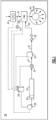
- An aircraft 20 is shown schematically in Figure 1 having a thermal load 22.
- the thermal load 22 is a component on the aircraft which generates a high amount of heat that is desirably cooled.
- the thermal load 22 may be a directed energy weapon, such as a laser.
- a directed energy weapon such as a laser.
- Such a system is operated at unpredictable intervals, and only periodically. However, when used it generates a large amount of heat. The thermal load must then be cooled, not only for the continued operation of the system, but also to reduce the aircraft's heat envelope and potential detection.
- thermal load 22 may be power electronics as associated with any number of components on the aircraft.
- the aircraft 20 is a military aircraft.
- Other systems which have periodic high thermal loads may include communication systems, radar jamming systems, etc.
- the thermal load 22 is provided with a cooling fluid supply system.
- a stepper motor 28 controls the position of a piston 30.
- the piston 30 moves within a storage tank 32 for a cooling liquid.
- the cooling liquid is combustible and is also soluble in the fuel utilized by the aircraft gas turbine engine.
- a controller 26 controls the supply system including the control valve 34 and the stepper motor 28 to deliver a precise volume of the cooling liquid into a line 31 and across the thermal load 22.
- the cooling liquid Downstream of the thermal load 22 the cooling liquid passes into a line 33 and through a check valve 36. The liquid then is delivered into a conduit 42 communicating the cooling liquid into a fuel metering unit 38.
- the fuel metering unit 38 also receives aviation fuel through a line 41 connected to a high pressure pump 40. From the fuel metering unit, the fuel passes into a combustor 44 in the aircraft's gas turbine engine(s). The mixed cooling fluid and aviation fuel flow through fuel injectors 46 into combustor 44.
- Figure 2 is a graph showing the amount of liquid natural gas which is soluble within aviation fuel across a temperature range at a pressure of 100 atm.
- the determination of the volume of liquid natural gas which is soluble in aviation fuel may be determined from a standard test method for estimation of solubility of gasses and petroleum and other organic liquids.
- ASTM D3827-92 is an example of a standard test method.
- liquid natural gas is soluble at 22-24 grams/kilogram of fuel.
- controller 26 may control the stepper motor 28 and control valve 34 along with the fuel metering unit 38 to deliver cooling fluid across the thermal load 22 at those relative weight percentages to the weight of the fuel being delivered into line 41.
- this cooling liquid When this cooling liquid is delivered into the fuel metering unit 38, and eventually the fuel injectors 46, it is combusted and passes outwardly of the gas turbine engine.
- the liquid natural gas provides not only cooling for the thermal load 22, but also provides energy content for the engine 44. Also, no storage for spent cooling fluid is needed.
- liquid natural gas is specifically mentioned, it is known that its main component is methane.
- the cooling fluid is a liquid containing methane.
- pure methane may be utilized.
- ammonia may be utilized as the cooling fluid. While ammonia might have a lower cooling capacity than the liquid natural gas, it still would have a significant cooling capacity.
- ammonia would be soluble to about 2.5 grams/kilogram of aviation fuel.
- a method and data for determining the solubility of ammonia across a pressure and temperature range may be found in Ammonia, Amines, Phosphine, Arsine, Stibine, Silane, Germane and Stannane in Organic Solvents by Young, C. L.; Fogg, P. G. T.
- the liquid natural gas may be cooled to be below 0 °F (-17.8°C). In other applications, it may be cooled to be below -200 °F (-128.9°C).
- the ammonia may also be cooled.
- the controller 26 is shown receiving information from the fuel pump 40. This information would provide the pressure and temperature of the fuel being delivered into line 41.
- the controller is programmed to determine a percentage solubility based upon that pressure and temperature.
- a look up table may be used based upon the included cooling liquid. Of course, other ways of determining a pressure and temperature of the fuel may be used.
- the fuel pump 40 might have embedded sensors for determining the pressure and temperature of the fuel.
- a sensor 43 could be placed on the line 41 downstream of the pump 40.
- the sensor could be embedded within the fuel metering unit 38.
- the controller may be part of a full authority digital electronic controller (“FADEC”) for the entire engine or may be a standalone controller.
- FADEC full authority digital electronic controller
- the cooling fluid is injected into the aviation fuel at less than 5% weight of the aviation fuel. More particularly, the cooling fluid is injected at a percentage which is less than its estimated solubility. Thus, the cooling fluid might be injected in a weight percentage between 0.1% and 2.2%.
- acceptable coolants can be described as a fluid which is a liquid at temperatures ⁇ 0 °F (-17.8°FC) and has a specific heat capacity equal to or greater than the aviation fuel.
- the cooling liquid must also be soluble in the main aircraft fuel and be combustible in the fuel-coolant-air mixture found in the combustor.
- An aircraft system under this disclosure could be said to include a thermal load, a controller, a tank for storing a cooling liquid, and a supply system for moving the cooling liquid outwardly of the tank and through a control valve to the thermal load.
- the controller is programmed to control the supply system.
- a conduit downstream of the thermal load is configured to communicate the cooling liquid to a fuel metering unit.
- the fuel metering unit also receives fuel from a high pressure pump.
- the fuel metering unit is configured to deliver a mixture of the cooling liquid and the fuel into a combustor on an associated aircraft engine.
- the controller is programmed to determine a percentage solubility of the cooling fluid into the fuel at a detected temperature and pressure of the fuel reaching the fuel metering unit.
- the cooling fluid is combustible and soluble in the fuel.
- a method of operating an aircraft system under this disclosure could be said to include moving a cooling liquid through a control valve to a thermal load, and downstream of the thermal load communicating the cooling liquid to a fuel metering unit.
- the fuel metering unit also receiving fuel from a high pressure pump.
- the fuel metering unit delivers a mixture of the cooling liquid and the fuel into a combustor on an associated aircraft engine.
- a percentage solubility of the cooling fluid into the fuel is determined at a temperature and pressure of the fuel reaching the fuel metering unit, and the determined percentage solubility is used to determine an amount of the cooling fluid to be delivered across the heat load.
Landscapes
- Engineering & Computer Science (AREA)
- Chemical & Material Sciences (AREA)
- Combustion & Propulsion (AREA)
- Mechanical Engineering (AREA)
- General Engineering & Computer Science (AREA)
- Aviation & Aerospace Engineering (AREA)
- Fuel-Injection Apparatus (AREA)
- Filling Or Discharging Of Gas Storage Vessels (AREA)
Abstract
An aircraft system includes a thermal load (22), a controller (26), a tank (32) for storing a cooling liquid, and a supply system for moving the cooling liquid outwardly of the tank and through a control valve (34) to the thermal load. A controller is programmed to control the supply system. A conduit (42) downstream of the thermal load is configured to communicate the cooling liquid to a fuel metering unit. The fuel metering unit also receives fuel from a high pressure pump. The fuel metering unit is configured to deliver a mixture of the cooling liquid and the fuel into a combustor on an associated aircraft engine. The controller programmed to determine a percentage solubility of the cooling fluid into the fuel at a detected temperature and pressure of the fuel reaching the fuel metering unit. The cooling fluid is combustible and soluble in the fuel. An aircraft and a method are also disclosed.
Description
- This application relates to an aircraft system and method wherein a cooling fluid for a heat load is combusted in a combustor of an engine.
- Aircraft are being provided with increasingly sophisticated systems. Many of these systems create a heat load. As one example, a directed energy weapon or laser, may be used at unpredictable intervals. When used it creates a high heat load on the aircraft.
- It is desirable to cool the system to preserve its operation. In addition, especially on military aircraft, it is important to mask the heat envelope of the aircraft. As such, cooling for such systems is important.
- Other heat loads that may exist on an aircraft include power electronic controls, communication systems, radar jamming systems, etc.
- While it has been proposed to use a cryogenic liquid as a heat sink, this would add a large parasitic load to the aircraft. It would include the weight of the cryogenic liquid itself, plus the weight of two tanks, one for storage before and another for storage after use. In addition, auxiliary components would be required.
- An aircraft system includes a thermal load, a controller, a tank for storing a cooling liquid, and a supply system for moving the cooling liquid outwardly of the tank and through a control valve to the thermal load. A controller is programmed to control the supply system. A conduit downstream of the thermal load is configured to communicate the cooling liquid to a fuel metering unit. The fuel metering unit also receives fuel from a high pressure pump. The fuel metering unit is configured to deliver a mixture of the cooling liquid and the fuel into a combustor on an associated aircraft engine. The controller is programmed to determine a percentage solubility of the cooling fluid into the fuel at a detected temperature and pressure of the fuel reaching the fuel metering unit. The cooling fluid is combustible and soluble in the fuel.
- An aircraft and a method are also disclosed.
- These and other features will be best understood from the following drawings and specification, the following is a brief description.
-
-
Figure 1 schematically shows an aircraft with a fuel mixture cooling system. -
Figure 2 is a graph showing solubility of liquid natural gas in aviation fuel across a temperature range, and at a particular pressure. - Applicant has recognized that certain combustible liquids are soluble in the fuel utilized by aircraft gas turbine engines. Aircraft gas turbine engines typically utilize aviation fuel.
- A combustible liquid, which is soluble in aviation fuel, may be utilized to cool a thermal load on an aircraft. That liquid can then be sent to mix with the aviation fuel and burned in a combustor of the gas turbine engine. This eliminates any need for storing the cooling fluid after use, and also provides energy benefits.
- An
aircraft 20 is shown schematically inFigure 1 having athermal load 22. Thethermal load 22 is a component on the aircraft which generates a high amount of heat that is desirably cooled. - As one example, the
thermal load 22 may be a directed energy weapon, such as a laser. Such a system is operated at unpredictable intervals, and only periodically. However, when used it generates a large amount of heat. The thermal load must then be cooled, not only for the continued operation of the system, but also to reduce the aircraft's heat envelope and potential detection. - Another application for the
thermal load 22 may be power electronics as associated with any number of components on the aircraft. In one application theaircraft 20 is a military aircraft. - Other systems which have periodic high thermal loads may include communication systems, radar jamming systems, etc.
- As shown in
Figure 1 , thethermal load 22 is provided with a cooling fluid supply system. In one method of driving the cooling fluid a stepper motor 28 controls the position of apiston 30. Thepiston 30 moves within astorage tank 32 for a cooling liquid. The cooling liquid is combustible and is also soluble in the fuel utilized by the aircraft gas turbine engine. - From the
tank 32 the cooling liquid passes through a control valve 34. Acontroller 26 controls the supply system including the control valve 34 and the stepper motor 28 to deliver a precise volume of the cooling liquid into aline 31 and across thethermal load 22. - Downstream of the
thermal load 22 the cooling liquid passes into aline 33 and through acheck valve 36. The liquid then is delivered into a conduit 42 communicating the cooling liquid into afuel metering unit 38. - The
fuel metering unit 38 also receives aviation fuel through aline 41 connected to ahigh pressure pump 40. From the fuel metering unit, the fuel passes into acombustor 44 in the aircraft's gas turbine engine(s). The mixed cooling fluid and aviation fuel flow throughfuel injectors 46 intocombustor 44. - We have recognized there are cooling fluids which are capable of providing a large amount of cooling but are also soluble at small percentages in aviation fuel.
- As an example,
Figure 2 is a graph showing the amount of liquid natural gas which is soluble within aviation fuel across a temperature range at a pressure of 100 atm. - The determination of the volume of liquid natural gas which is soluble in aviation fuel may be determined from a standard test method for estimation of solubility of gasses and petroleum and other organic liquids. ASTM D3827-92 is an example of a standard test method.
- As shown in
Figure 2 at a particular pressure and temperature expected in a fighter jet fuel system downstream ofhigh pressure pump 40, liquid natural gas is soluble at 22-24 grams/kilogram of fuel. - Now,
controller 26 may control the stepper motor 28 and control valve 34 along with thefuel metering unit 38 to deliver cooling fluid across thethermal load 22 at those relative weight percentages to the weight of the fuel being delivered intoline 41. - When this cooling liquid is delivered into the
fuel metering unit 38, and eventually thefuel injectors 46, it is combusted and passes outwardly of the gas turbine engine. Thus, the liquid natural gas provides not only cooling for thethermal load 22, but also provides energy content for theengine 44. Also, no storage for spent cooling fluid is needed. - While liquid natural gas is specifically mentioned, it is known that its main component is methane. Thus, it could be said that the cooling fluid is a liquid containing methane. As an example, perhaps pure methane may be utilized.
- In another embodiment, ammonia may be utilized as the cooling fluid. While ammonia might have a lower cooling capacity than the liquid natural gas, it still would have a significant cooling capacity.
- Also, at the pressures and temperatures expected downstream of the
high pressure pump 40, the ammonia would be soluble to about 2.5 grams/kilogram of aviation fuel. - A method and data for determining the solubility of ammonia across a pressure and temperature range may be found in Ammonia, Amines, Phosphine, Arsine, Stibine, Silane, Germane and Stannane in Organic Solvents by Young, C. L.; Fogg, P. G. T.
- The liquid natural gas may be cooled to be below 0 °F (-17.8°C). In other applications, it may be cooled to be below -200 °F (-128.9°C). The ammonia may also be cooled.
- The
controller 26 is shown receiving information from thefuel pump 40. This information would provide the pressure and temperature of the fuel being delivered intoline 41. The controller is programmed to determine a percentage solubility based upon that pressure and temperature. A look up table may be used based upon the included cooling liquid. Of course, other ways of determining a pressure and temperature of the fuel may be used. - The
fuel pump 40 might have embedded sensors for determining the pressure and temperature of the fuel. Alternatively, asensor 43 could be placed on theline 41 downstream of thepump 40. For that matter the sensor could be embedded within thefuel metering unit 38. - The controller may be part of a full authority digital electronic controller ("FADEC") for the entire engine or may be a standalone controller.
- In general, it could be said that the cooling fluid is injected into the aviation fuel at less than 5% weight of the aviation fuel. More particularly, the cooling fluid is injected at a percentage which is less than its estimated solubility. Thus, the cooling fluid might be injected in a weight percentage between 0.1% and 2.2%.
- Broadly, acceptable coolants can be described as a fluid which is a liquid at temperatures <0 °F (-17.8°FC) and has a specific heat capacity equal to or greater than the aviation fuel. The cooling liquid must also be soluble in the main aircraft fuel and be combustible in the fuel-coolant-air mixture found in the combustor.
- An aircraft system under this disclosure could be said to include a thermal load, a controller, a tank for storing a cooling liquid, and a supply system for moving the cooling liquid outwardly of the tank and through a control valve to the thermal load. The controller is programmed to control the supply system. A conduit downstream of the thermal load is configured to communicate the cooling liquid to a fuel metering unit. The fuel metering unit also receives fuel from a high pressure pump. The fuel metering unit is configured to deliver a mixture of the cooling liquid and the fuel into a combustor on an associated aircraft engine. The controller is programmed to determine a percentage solubility of the cooling fluid into the fuel at a detected temperature and pressure of the fuel reaching the fuel metering unit. The cooling fluid is combustible and soluble in the fuel.
- A method of operating an aircraft system under this disclosure could be said to include moving a cooling liquid through a control valve to a thermal load, and downstream of the thermal load communicating the cooling liquid to a fuel metering unit. The fuel metering unit also receiving fuel from a high pressure pump. The fuel metering unit delivers a mixture of the cooling liquid and the fuel into a combustor on an associated aircraft engine. A percentage solubility of the cooling fluid into the fuel is determined at a temperature and pressure of the fuel reaching the fuel metering unit, and the determined percentage solubility is used to determine an amount of the cooling fluid to be delivered across the heat load.
- Although embodiments have been disclosed, a worker of skill in this art would recognize that certain modifications would come within the scope of the invention as defined by the claims.
Claims (14)
- An aircraft system comprising:a thermal load (22);a controller (26), a tank (32) for storing a cooling liquid, and a supply system for moving the cooling liquid outwardly of the tank and through a control valve (34) to the thermal load, said controller being programmed to control the supply system, a conduit (42) downstream of the thermal load configured to communicate the cooling liquid to a fuel metering unit, the fuel metering unit also receiving fuel from a high pressure pump, and the fuel metering unit configured to deliver a mixture of the cooling liquid and the fuel into a combustor on an associated aircraft engine;the controller being programmed to determine a percentage solubility of the cooling fluid into the fuel at a detected temperature and pressure of the fuel reaching the fuel metering unit; andwherein the cooling fluid is combustible and soluble in the fuel.
- The system as set forth in claim 1, wherein the percentage solubility is less than 5%.
- The system as set forth in claim 2, wherein the percentage solubility is between 0.1% and 2.2%.
- The system as set forth in claim 1, 2 or 3, wherein the cooling liquid at the storage tank is at a temperature below 0 °F (-17.8°C).
- The system as set forth in any preceding claim, wherein the cooling fluid includes methane.
- The system as set forth in any of claims 1 to 4, wherein the cooling fluid is ammonia.
- The system as set forth in any preceding claim, wherein the thermal load (22) is one of a communication system, a directed energy weapon, a radar jamming system, or an electronic control.
- The system as set forth in any preceding claim, wherein the thermal load (22) is created at unpredictable intervals and creates a high cooling load at the thermal load.
- An aircraft comprising:an aircraft body;a system as claimed in any preceding claim, the aircraft body holding the thermal load.
- A method of operating an aircraft system:moving a cooling liquid, that is combustible and soluble in aviation fuel, through a control valve (34) to a thermal load (22), downstream of the thermal load communicating the cooling liquid to a fuel metering unit (38), the fuel metering unit also receiving fuel from a high pressure pump (40), and the fuel metering unit delivering a mixture of the cooling liquid and the fuel into a combustor (44) on an associated aircraft engine; anddetermining a percentage solubility of the cooling fluid into the fuel at a temperature and pressure of the fuel reaching the fuel metering unit and using the determined percentage solubility to determine an amount of the cooling fluid to be delivered across the heat load.
- The method as set forth in claim 10, wherein the solubility of less than 5%.
- The method as set forth in claim 10 or 11, wherein the cooling fluid contains methane.
- The method as set forth in claim 10 or 11, wherein the cooling fluid is ammonia.
- The method as set forth in any of claims 10 to 13, wherein the thermal load is created at unpredictable intervals and creates a high cooling load at the thermal load.
Applications Claiming Priority (1)
| Application Number | Priority Date | Filing Date | Title |
|---|---|---|---|
| US18/202,606 US12221222B2 (en) | 2023-05-26 | 2023-05-26 | Cooling fluid used as secondary fuel source |
Publications (1)
| Publication Number | Publication Date |
|---|---|
| EP4467791A1 true EP4467791A1 (en) | 2024-11-27 |
Family
ID=91248172
Family Applications (1)
| Application Number | Title | Priority Date | Filing Date |
|---|---|---|---|
| EP24177773.9A Pending EP4467791A1 (en) | 2023-05-26 | 2024-05-23 | Cooling fluid used as secondary fuel source |
Country Status (2)
| Country | Link |
|---|---|
| US (1) | US12221222B2 (en) |
| EP (1) | EP4467791A1 (en) |
Citations (3)
| Publication number | Priority date | Publication date | Assignee | Title |
|---|---|---|---|---|
| US20120167547A1 (en) * | 2011-01-03 | 2012-07-05 | Hua Zhang | Combustion turbine purge system and method of assembling same |
| US20150315971A1 (en) * | 2013-10-21 | 2015-11-05 | Government Of The United States As Represented By The Secretary Of The Air Force | High-speed vehicle power and thermal management system and methods of use therefor |
| US20160195013A1 (en) * | 2012-12-28 | 2016-07-07 | General Electric Company | Cryogenic fuel compositions and dual fuel aircraft system |
Family Cites Families (15)
| Publication number | Priority date | Publication date | Assignee | Title |
|---|---|---|---|---|
| AU8122794A (en) * | 1993-10-19 | 1995-05-08 | State Of California Energy Resources Conservation And Development Commission | Performance enhanced gas turbine powerplants |
| JP2015505595A (en) * | 2012-02-01 | 2015-02-23 | ゼネラル・エレクトリック・カンパニイ | Combustor assembly for gas turbomachine with liquid fuel start system |
| US9957892B2 (en) | 2012-06-20 | 2018-05-01 | Daniel POMERLEAU | Jet turbine utilizing a cryogenic fuel |
| US9765691B2 (en) | 2012-12-28 | 2017-09-19 | General Electric Company | Turbine engine assembly and dual fuel aircraft system |
| US20150337730A1 (en) * | 2012-12-28 | 2015-11-26 | General Electric Company | Turbine engine assemblies |
| GB201317731D0 (en) * | 2013-10-08 | 2013-11-20 | Rolls Royce Plc | Fuel delivery system |
| US10100748B2 (en) | 2014-09-15 | 2018-10-16 | The Boeing Company | Dual fuel gas turbine thrust and power control |
| GB201420989D0 (en) * | 2014-11-26 | 2015-01-07 | Rolls Royce Plc | Aircraft engine fuel system |
| CN104948303B (en) | 2015-05-25 | 2017-11-17 | 沈阳航空航天大学 | A kind of fuel system applied to the aero-engine that LNG is fuel |
| US20210229827A1 (en) * | 2015-10-08 | 2021-07-29 | Government Of The United States, As Represented By The Secretary Of The Air Force | Thermal management system and method of using same |
| JP6772925B2 (en) * | 2017-03-27 | 2020-10-21 | 株式会社Ihi | Combustion equipment and gas turbine engine system |
| US11041439B2 (en) | 2018-09-14 | 2021-06-22 | Raytheon Technologies Corporation | Hybrid expander cycle with turbo-generator and cooled power electronics |
| GB2578288B (en) | 2018-10-15 | 2022-04-13 | Gkn Aerospace Services Ltd | Apparatus |
| GB202016379D0 (en) * | 2020-10-15 | 2020-12-02 | Airbus Operations Ltd | Dual fuel aircraft |
| CN115042977B (en) | 2022-07-06 | 2024-12-20 | 北京航空航天大学 | Aircraft thermal management system for megawatt-class heat loads using low-temperature consumable heat sinks |
-
2023
- 2023-05-26 US US18/202,606 patent/US12221222B2/en active Active
-
2024
- 2024-05-23 EP EP24177773.9A patent/EP4467791A1/en active Pending
Patent Citations (3)
| Publication number | Priority date | Publication date | Assignee | Title |
|---|---|---|---|---|
| US20120167547A1 (en) * | 2011-01-03 | 2012-07-05 | Hua Zhang | Combustion turbine purge system and method of assembling same |
| US20160195013A1 (en) * | 2012-12-28 | 2016-07-07 | General Electric Company | Cryogenic fuel compositions and dual fuel aircraft system |
| US20150315971A1 (en) * | 2013-10-21 | 2015-11-05 | Government Of The United States As Represented By The Secretary Of The Air Force | High-speed vehicle power and thermal management system and methods of use therefor |
Also Published As
| Publication number | Publication date |
|---|---|
| US20240391602A1 (en) | 2024-11-28 |
| US12221222B2 (en) | 2025-02-11 |
Similar Documents
| Publication | Publication Date | Title |
|---|---|---|
| EP3102809B1 (en) | Technique for optimizing engine performance using fuel temperature | |
| US9656762B2 (en) | System for temperature and actuation control and method of controlling fluid temperatures in an aircraft | |
| US5918679A (en) | Fire safety system | |
| CN104884766B (en) | Turbine engine components and double fuel aerocraft system | |
| US8430361B2 (en) | Method and device enabling a rocket engine pump to be driven by an internal combustion engine | |
| US20160195013A1 (en) | Cryogenic fuel compositions and dual fuel aircraft system | |
| KR20180075608A (en) | Ship | |
| JP2016502622A (en) | Turbine engine assembly and dual fuel aircraft system | |
| CN104010915A (en) | Method and apparatus for supplying a gaseous fuel to an internal combustion engine | |
| EP3049665B1 (en) | Fuel supply system for an internal combustion engine and relative fuel change over procedure | |
| US7926403B1 (en) | Transient, high rate, closed system cryogenic injection | |
| EP4474628A1 (en) | Gas turbine engine hydrogen supply system and method | |
| US12221222B2 (en) | Cooling fluid used as secondary fuel source | |
| US10415509B2 (en) | Cooling system for cryogenic fuel delivery components | |
| Mangold et al. | Refueling of LH2 aircraft—assessment of turnaround procedures and aircraft design implication. Energies 2022; 15: 2475 | |
| Urbach et al. | Water injection into navy gas-turbine combustors to reduce NOx emissions | |
| Yilanli et al. | Aircraft fuel system energy and exergy analysis under hot day conditions | |
| JP2001115916A (en) | Diesel engine for dimethyl ether | |
| US20250264063A1 (en) | Aircraft comprising a gas turbine engine having primary and secondary fuel-injectors | |
| Langel et al. | Test verification of the cryogenic Vinci thrust chamber | |
| Roberts | Development, Testing, and Validation of a Heat Transfer Model for Bi-Propellant Liquid Rocket Engines | |
| Mccurdy | Model Specification Liquid Propellant Rocket Engine Rocketdyne Model YLR101-NA-15 (VERNIER) | |
| Schneider et al. | Design, Fabrication, and Test of a LOX/LCH4 RCS Igniter at NASA | |
| Boyd et al. | Space tug propulsion system failure mode, effects and criticality analysis | |
| CN121969555A (en) | Fuel conditioning system for supplying fuel from a cryogenic tank to an aircraft propulsion system and related method |
Legal Events
| Date | Code | Title | Description |
|---|---|---|---|
| PUAI | Public reference made under article 153(3) epc to a published international application that has entered the european phase |
Free format text: ORIGINAL CODE: 0009012 |
|
| STAA | Information on the status of an ep patent application or granted ep patent |
Free format text: STATUS: THE APPLICATION HAS BEEN PUBLISHED |
|
| AK | Designated contracting states |
Kind code of ref document: A1 Designated state(s): AL AT BE BG CH CY CZ DE DK EE ES FI FR GB GR HR HU IE IS IT LI LT LU LV MC ME MK MT NL NO PL PT RO RS SE SI SK SM TR |
|
| STAA | Information on the status of an ep patent application or granted ep patent |
Free format text: STATUS: REQUEST FOR EXAMINATION WAS MADE |
|
| 17P | Request for examination filed |
Effective date: 20250527 |