EP4467790A1 - Condenser for steam-injected engine - Google Patents
Condenser for steam-injected engine Download PDFInfo
- Publication number
- EP4467790A1 EP4467790A1 EP24177757.2A EP24177757A EP4467790A1 EP 4467790 A1 EP4467790 A1 EP 4467790A1 EP 24177757 A EP24177757 A EP 24177757A EP 4467790 A1 EP4467790 A1 EP 4467790A1
- Authority
- EP
- European Patent Office
- Prior art keywords
- water
- exhaust gas
- gas flow
- flow
- water tank
- Prior art date
- Legal status (The legal status is an assumption and is not a legal conclusion. Google has not performed a legal analysis and makes no representation as to the accuracy of the status listed.)
- Pending
Links
Images

Classifications
-
- F—MECHANICAL ENGINEERING; LIGHTING; HEATING; WEAPONS; BLASTING
- F02—COMBUSTION ENGINES; HOT-GAS OR COMBUSTION-PRODUCT ENGINE PLANTS
- F02C—GAS-TURBINE PLANTS; AIR INTAKES FOR JET-PROPULSION PLANTS; CONTROLLING FUEL SUPPLY IN AIR-BREATHING JET-PROPULSION PLANTS
- F02C3/00—Gas-turbine plants characterised by the use of combustion products as the working fluid
- F02C3/20—Gas-turbine plants characterised by the use of combustion products as the working fluid using a special fuel, oxidant, or dilution fluid to generate the combustion products
- F02C3/30—Adding water, steam or other fluids for influencing combustion, e.g. to obtain cleaner exhaust gases
-
- F—MECHANICAL ENGINEERING; LIGHTING; HEATING; WEAPONS; BLASTING
- F01—MACHINES OR ENGINES IN GENERAL; ENGINE PLANTS IN GENERAL; STEAM ENGINES
- F01D—NON-POSITIVE DISPLACEMENT MACHINES OR ENGINES, e.g. STEAM TURBINES
- F01D25/00—Component parts, details, or accessories, not provided for in, or of interest apart from, other groups
- F01D25/32—Collecting of condensation water; Drainage ; Removing solid particles
-
- F—MECHANICAL ENGINEERING; LIGHTING; HEATING; WEAPONS; BLASTING
- F01—MACHINES OR ENGINES IN GENERAL; ENGINE PLANTS IN GENERAL; STEAM ENGINES
- F01N—GAS-FLOW SILENCERS OR EXHAUST APPARATUS FOR MACHINES OR ENGINES IN GENERAL; GAS-FLOW SILENCERS OR EXHAUST APPARATUS FOR INTERNAL-COMBUSTION ENGINES
- F01N3/00—Exhaust or silencing apparatus having means for purifying, rendering innocuous, or otherwise treating exhaust
- F01N3/005—Exhaust or silencing apparatus having means for purifying, rendering innocuous, or otherwise treating exhaust for draining or otherwise eliminating condensates or moisture accumulating in the apparatus
-
- F—MECHANICAL ENGINEERING; LIGHTING; HEATING; WEAPONS; BLASTING
- F02—COMBUSTION ENGINES; HOT-GAS OR COMBUSTION-PRODUCT ENGINE PLANTS
- F02C—GAS-TURBINE PLANTS; AIR INTAKES FOR JET-PROPULSION PLANTS; CONTROLLING FUEL SUPPLY IN AIR-BREATHING JET-PROPULSION PLANTS
- F02C3/00—Gas-turbine plants characterised by the use of combustion products as the working fluid
- F02C3/20—Gas-turbine plants characterised by the use of combustion products as the working fluid using a special fuel, oxidant, or dilution fluid to generate the combustion products
- F02C3/22—Gas-turbine plants characterised by the use of combustion products as the working fluid using a special fuel, oxidant, or dilution fluid to generate the combustion products the fuel or oxidant being gaseous at standard temperature and pressure
-
- F—MECHANICAL ENGINEERING; LIGHTING; HEATING; WEAPONS; BLASTING
- F02—COMBUSTION ENGINES; HOT-GAS OR COMBUSTION-PRODUCT ENGINE PLANTS
- F02C—GAS-TURBINE PLANTS; AIR INTAKES FOR JET-PROPULSION PLANTS; CONTROLLING FUEL SUPPLY IN AIR-BREATHING JET-PROPULSION PLANTS
- F02C3/00—Gas-turbine plants characterised by the use of combustion products as the working fluid
- F02C3/20—Gas-turbine plants characterised by the use of combustion products as the working fluid using a special fuel, oxidant, or dilution fluid to generate the combustion products
- F02C3/30—Adding water, steam or other fluids for influencing combustion, e.g. to obtain cleaner exhaust gases
- F02C3/305—Increasing the power, speed, torque or efficiency of a gas turbine or the thrust of a turbojet engine by injecting or adding water, steam or other fluids
-
- F—MECHANICAL ENGINEERING; LIGHTING; HEATING; WEAPONS; BLASTING
- F02—COMBUSTION ENGINES; HOT-GAS OR COMBUSTION-PRODUCT ENGINE PLANTS
- F02C—GAS-TURBINE PLANTS; AIR INTAKES FOR JET-PROPULSION PLANTS; CONTROLLING FUEL SUPPLY IN AIR-BREATHING JET-PROPULSION PLANTS
- F02C6/00—Plural gas-turbine plants; Combinations of gas-turbine plants with other apparatus; Adaptations of gas-turbine plants for special use
- F02C6/04—Gas-turbine plants providing heated or pressurised working fluid for other apparatus, e.g. without mechanical power output
-
- F—MECHANICAL ENGINEERING; LIGHTING; HEATING; WEAPONS; BLASTING
- F02—COMBUSTION ENGINES; HOT-GAS OR COMBUSTION-PRODUCT ENGINE PLANTS
- F02C—GAS-TURBINE PLANTS; AIR INTAKES FOR JET-PROPULSION PLANTS; CONTROLLING FUEL SUPPLY IN AIR-BREATHING JET-PROPULSION PLANTS
- F02C7/00—Features, components parts, details or accessories, not provided for in, or of interest apart form groups F02C1/00 - F02C6/00; Air intakes for jet-propulsion plants
- F02C7/12—Cooling of plants
- F02C7/16—Cooling of plants characterised by cooling medium
-
- F—MECHANICAL ENGINEERING; LIGHTING; HEATING; WEAPONS; BLASTING
- F05—INDEXING SCHEMES RELATING TO ENGINES OR PUMPS IN VARIOUS SUBCLASSES OF CLASSES F01-F04
- F05D—INDEXING SCHEME FOR ASPECTS RELATING TO NON-POSITIVE-DISPLACEMENT MACHINES OR ENGINES, GAS-TURBINES OR JET-PROPULSION PLANTS
- F05D2260/00—Function
- F05D2260/20—Heat transfer, e.g. cooling
- F05D2260/213—Heat transfer, e.g. cooling by the provision of a heat exchanger within the cooling circuit
Definitions
- the present invention relates generally to an aircraft propulsion system that includes a steam generation system transforming recovered water into a steam flow for injection into a core flow.
- Turbine engines compress incoming core airflow, mix the compressed airflow with fuel that is ignited in a combustor to generate an exhaust gas flow.
- Steam injection can provide improved propulsive efficiencies by increasing mass flow without additional work by the compressor section.
- Water recovered from the exhaust gas flow may be transformed into steam using thermal energy from the exhaust gas flow.
- Water recovery and steam generation utilize heat exchangers to condense and vaporize water into steam that are exposed to the high temperatures and pressures of the exhaust gas flow. The high temperature and pressures present challenges to the configuration and operational life of condenser and evaporator heat exchangers.
- a turbine engine assembly includes, among other possible things, a compressor section where an inlet airflow is compressed, a combustor section where the compressed inlet airflow is mixed with fuel and ignited to generate an exhaust gas flow, a turbine section through which the exhaust gas flow is expanded to generate a mechanical power output, a condenser system that includes a water tank that is configured for extracting water from the exhaust gas flow by communicating the exhaust gas flow directly through a volume of water within the water tank, and an evaporator system that is at least partially exposed to the exhaust gas flow where thermal energy from the exhaust gas flow is utilized to generate a steam flow from at least a portion of water that is extracted by the condenser system for injection into a core flow path.
- the turbine engine assembly includes an exhaust gas distribution system within the water tank where the exhaust gas flow entering the water tank is spread out into the volume of water.
- the turbine engine assembly includes a circulation system for cooling the volume of water in the water tank.
- the circulation system includes a heat exchanger where a flow of water from the water tank is placed in thermal communication with a cooling flow.
- the water tank includes baffles for controlling movement of the volume of water within the water tank.
- the water tank includes an annularly shaped portion where the exhaust gas flow and a water flow generate a rotational flow for condensing and separating water from the exhaust gas flow.
- the turbine engine assembly includes at least one liquid collector that is disposed on a radially outer surface of the annular shaped portion of the water tank for collecting liquid from the exhaust as flow.
- the annularly shaped portion includes a gas permeable membrane and a portion of the exhaust gas flow is communicated through the gas permeable membrane and out through a gas outlet.
- the turbine engine assembly includes a nacelle that surrounds the compressor section, combustor section and turbine section and at least a portion of the water tank is disposed in a bottom portion of the nacelle.
- a steam generation system for an aircraft propulsion system includes, among other possible things, a condenser system that includes a water tank where water is extracted from an exhaust gas flow by communication directly through a volume of water within the water tank, and an evaporator system where thermal energy (for example, from the exhaust gas flow) is utilized to generate a steam flow from at least a portion of water that is extracted by the condenser system.
- a condenser system that includes a water tank where water is extracted from an exhaust gas flow by communication directly through a volume of water within the water tank, and an evaporator system where thermal energy (for example, from the exhaust gas flow) is utilized to generate a steam flow from at least a portion of water that is extracted by the condenser system.
- the steam generation system includes a distribution system within the water tank where the exhaust gas flow entering the water tank is spread out within the volume of water.
- the steam generation system includes a circulation system for cooling the volume of water in water tank.
- the circulation system includes a heat exchanger where a flow of water from the water tank is placed in thermal communication with a cooling flow.
- the water tank includes internal baffles for controlling movement of the volume of water within the water tank.
- the water tank includes an annularly shaped portion where at least a portion of the exhaust gas flow and a water flow are introduced tangentially to generate a rotational flow where water from the exhaust gas flow is condensed and separated from the exhaust gas flow.
- the annularly shaped portion includes a gas permeable membrane and the exhaust gas flow is communicated through the gas permeable membrane to separate water from the exhaust gas flow.
- the water containing exhaust gas flow is introduced tangentially into an annularly shaped portion of the water tank to induce a rotational flow and the method further includes separating the liquid water from the gas flow utilizing the rotational flow within the annularly shaped portion of the water tank.
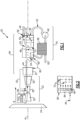
- Figure 1 schematically illustrates an example propulsion system 20 that includes a condenser system 34 including a water tank 36 where at least a portion of a water containing exhaust gas flow is communicated directly into a volume of water for condensing and extracting water for use in generating a steam flow for injection it a core flow path C.
- a condenser system 34 including a water tank 36 where at least a portion of a water containing exhaust gas flow is communicated directly into a volume of water for condensing and extracting water for use in generating a steam flow for injection it a core flow path C.
- the example propulsion system 20 includes a fan section 24 and a core engine 22.
- the core engine 22 includes a compressor section 26, a combustor section 28 and the turbine section 30 disposed along an engine longitudinal axis A.
- the fan section 24 drives inlet airflow along a bypass flow path B, while the compressor section 26 draws inlet air along the core flow path C.
- the inlet airflow is compressed and communicated to the combustor section 28 where the compressed core airflow is mixed with a fuel flow 98 from a fuel system 96 and ignited to generate an exhaust gas flow 44.
- the exhaust gas flow 44 expands through the turbine section 30 where energy is extracted and utilized to drive the fan section 24 and the compressor section 26.
- the example fuel system 96 is configured to provide a hydrogen-based fuel such as a liquid hydrogen (LH 2 ) to the combustor 28.
- a hydrogen-based fuel such as a liquid hydrogen (LH 2 )
- LH 2 liquid hydrogen
- hydrogen is disclosed by way of example, other non-carbon-based fuels, biofuels and/or other sustainable aviation fuels could be utilized and are within the contemplation of this disclosure.
- the disclosed features may also be beneficial in an engine configured to operate with traditional carbon-based fuels.
- a steam generation system 94 includes an evaporator 32 and a condenser system 34 that are disposed downstream of the turbine section 30 and receive the exhaust gas flow 44.
- the evaporator system 32 utilizes thermal energy from the exhaust gas flow 44 to generate a steam flow 52 from a water flow 60 extracted by the condenser system 34
- the condenser system 34 cools the exhaust gas flow 44 to extract water that is gathered in a tank 36 containing a volume of water 48.
- a separator 55 is disposed at the outlet 56 and accumulates any remaining liquid within the exhaust gas flow.
- the separator 55 may be a baffle, screen, grid or any other structure where liquid can coalesce and fall back into the tank 36. Any remaining exhaust gas flow has a reduced moisture content and is referenced as a dry exhaust gas flow 46 that is exhausted from the tank 36 and into the ambient environment.
- a temperature of the volume of water 48 is maintained by a cooling circulation system 42 that includes a pump 40 and a heat exchanger 38.
- a cooling flow 62 is communicated through the heat exchanger 38 to cool the water.
- a portion of the volume of water 48 within the tank 36 is pumped through the heat exchanger 38 and cooled.
- the cooling flow 62 in one example embodiment, is a portion of the inlet airflow through the fan 24.
- the cooling flow 62 may be a fuel flow.
- the example tank 36 includes baffles 72 arranged to reduce any sloshing or internal movement of the volume of water 48 during aircraft operation and maneuvering.
- the baffles 72 are static structures that extend transverse to both water and exhaust gas flow directions to reduce sloshing of the volume of water 48.
- a distributor 64 may be provided within the water tank 36 to distribute inlet exhaust gas flow 44 throughout the water tank 36.
- the example distributor 64 includes a plurality of openings 66 that inject the exhaust gas flow 44 throughout the volume of water 48.
- the distributor 64 may be arranged to communicate exhaust gas flow 44 at different locations within the tank 36.
- a single distributor 64 is shown schematically, several distributors 64 could be arranged throughout the water tank 36 to provide sufficient flow area as needed to condense water and enable sufficient flow through of the exhaust gas flow 44.
- FIG. 3 another example water tank 70 is shown schematically and is located within a bottom portion of a nacelle 68.
- the nacelle 68 includes an interior space 108.
- the water tank 70 may be supported at least partially within the interior space 108.
- a portion of the exhaust gas flow 44 may be communicated through the volume of water 48 contained within the tank 70.
- the water tank 70 is shown in Figure 3 as disposed within the nacelle 68 and operates as described above with regard to the example shown and described in Figure 1 .
- the example water tank 70 is shown and described as being supported in the nacelle 68, it is within the contemplation of this disclosure that the water tank 70 may be supported and located in other locations within the aircraft airframe and/or engine assembly 20.
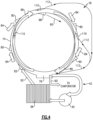
- another condenser system 78 is schematically shown and includes a water tank 76 and an annular portion 74.
- Inlet exhaust gas flows 84 are communicated tangentially into the annular portion 74 through inlets 80 to generate a rotational flow schematically indicated at 86.
- several inlets 80 are arranged about the annular portion 76 to induce rotational flow.
- the rotational flow 86 drives the heavier liquid water radially outward and into the water tank 76.
- the circulation system 42 pumps a portion of flow from the water tank 76 through the heat exchanger 38 and then through a water inlet 82.
- the water inlet 82 is arranged to introduce water inlet flow 92 tangentially into the annular portion 74.
- the cooled water inlet flow 92 mixes with the tangential exhaust gas flow 84 to generate rotation.
- Liquid water condensed out of the exhaust gas flow 84 is combined with the cooled water inlet flow 92 and communicated into the water tank 76.
- at least one water collector 110 is disposed on a radially outer wall for further collecting liquid and water for the exhaust gas flow.
- the liquid collectors 110 may be scoops as shown, grooves or porous regions to further separate liquid from the gas flow 84. Water flow 112 that is exhausted from the liquid collectors 110 is communicated back to the tank 76 as is schematically shown.
- the remaining dry gas flow 90 is exhausted through a radially inner gas outlet 88 and then into the ambient environment.
- the rotational flow about the annular portion 74 provides for both condensing of liquid and separation of water from the remaining gas portion that is exhausted as the dry gas flow 90.
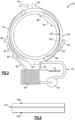
- the condenser system 100 includes the inlets 80 for introducing the exhaust gas flows 84 tangentially into the annular portion 74.
- a gas permeable membrane 102 is provided within the annular portion 74 and provides for separation of any gas flow from condensed liquid.
- the exhaust gas flow 84 is introduced through the inlets 80 and mixed with a cooled inlet water flow 92.
- the cooled inlet water flow 92 cools the exhaust gas flow 84 such that liquid water is condensed.
- the gas permeable membrane 102 provides for gas to pass through to a radially interior side of the annular portion 74. Accordingly, on a radially outer side of the permeable membrane is a mixture of water vapor, condensed water and gas flow as indicated at 106. The radially inner side of the permeable membrane 102 is substantially all a gas flow as indicated at 104. The gas component passes through the permeable membrane 102 and eventually out as the dry gas flow 90 through the outlet 88.
- the permeable membrane 102 may be formed utilizing any material determined to provide the desired separation of gas and water from the rotational mixed flow of water and gas in the annular portion 74. Moreover, the structure of the permeable membrane 102 may include layers of support and permeable material that prevent liquid flow and enable gas flow.
- the annular portion 74 of the example condenser systems 78 and 100 shown schematically in Figures 4 and 5 may be arranged about the longitudinal axis A with appropriate ducting provided for communicating the gas flows 84 into the annular portion 74.
- the annular portion 74 may be arranged and mounted within an engine nacelle 68 or other engine structures and remain within the scope and contemplation of this disclosure.
Landscapes
- Engineering & Computer Science (AREA)
- Chemical & Material Sciences (AREA)
- Combustion & Propulsion (AREA)
- Mechanical Engineering (AREA)
- General Engineering & Computer Science (AREA)
- Engine Equipment That Uses Special Cycles (AREA)
Abstract
A turbine engine assembly includes a compressor section (26), a combustor section (28), a turbine section (30), a condenser system (34) that includes a water tank (36) that is configured for extracting water from the exhaust gas flow (44) by communicating the exhaust gas flow (44) directly through a volume of water (48) within the water tank (36), and an evaporator system (32), that is at least partially exposed to the exhaust gas flow (44), where thermal energy from the exhaust gas flow (44) is utilized to generate a steam flow (52) from at least a portion of water that is extracted by the condenser system (34) for injection into a core flow path (C).
Description
- The present invention relates generally to an aircraft propulsion system that includes a steam generation system transforming recovered water into a steam flow for injection into a core flow.
- Reduction and/or elimination of carbon emissions generated by aircraft operation is a stated goal of aircraft manufacturers and airline operators. Turbine engines compress incoming core airflow, mix the compressed airflow with fuel that is ignited in a combustor to generate an exhaust gas flow. Steam injection can provide improved propulsive efficiencies by increasing mass flow without additional work by the compressor section. Water recovered from the exhaust gas flow may be transformed into steam using thermal energy from the exhaust gas flow. Water recovery and steam generation utilize heat exchangers to condense and vaporize water into steam that are exposed to the high temperatures and pressures of the exhaust gas flow. The high temperature and pressures present challenges to the configuration and operational life of condenser and evaporator heat exchangers.
- A turbine engine assembly according to an aspect of this invention includes, among other possible things, a compressor section where an inlet airflow is compressed, a combustor section where the compressed inlet airflow is mixed with fuel and ignited to generate an exhaust gas flow, a turbine section through which the exhaust gas flow is expanded to generate a mechanical power output, a condenser system that includes a water tank that is configured for extracting water from the exhaust gas flow by communicating the exhaust gas flow directly through a volume of water within the water tank, and an evaporator system that is at least partially exposed to the exhaust gas flow where thermal energy from the exhaust gas flow is utilized to generate a steam flow from at least a portion of water that is extracted by the condenser system for injection into a core flow path.
- Optionally, and in accordance with the above, the water tank includes an inlet for communicating the exhaust gas flow directly into the volume of water and an outlet for exhausting the exhaust gas flow.
- Optionally, and in accordance with any of the above, the turbine engine assembly includes a separator at the outlet for collecting any remaining water from the exhaust gas flow.
- Optionally, and in accordance with any of the above, the turbine engine assembly includes an exhaust gas distribution system within the water tank where the exhaust gas flow entering the water tank is spread out into the volume of water.
- Optionally, and in accordance with any of the above, the turbine engine assembly includes a circulation system for cooling the volume of water in the water tank. The circulation system includes a heat exchanger where a flow of water from the water tank is placed in thermal communication with a cooling flow.
- Optionally, and in accordance with any of the above, the water tank includes baffles for controlling movement of the volume of water within the water tank.
- Optionally, and in accordance with any of the above, the water tank includes an annularly shaped portion where the exhaust gas flow and a water flow generate a rotational flow for condensing and separating water from the exhaust gas flow.
- Optionally, and in accordance with any of the above, the turbine engine assembly includes at least one liquid collector that is disposed on a radially outer surface of the annular shaped portion of the water tank for collecting liquid from the exhaust as flow.
- Optionally, and in accordance with any of the above, the annularly shaped portion includes a gas permeable membrane and a portion of the exhaust gas flow is communicated through the gas permeable membrane and out through a gas outlet.
- Optionally, and in accordance with any of the above, the turbine engine assembly includes a nacelle that surrounds the compressor section, combustor section and turbine section and at least a portion of the water tank is disposed in a bottom portion of the nacelle.
- A steam generation system for an aircraft propulsion system according to another aspect of this invention includes, among other possible things, a condenser system that includes a water tank where water is extracted from an exhaust gas flow by communication directly through a volume of water within the water tank, and an evaporator system where thermal energy (for example, from the exhaust gas flow) is utilized to generate a steam flow from at least a portion of water that is extracted by the condenser system.
- Optionally, and in accordance with any of the above, the water tank includes an inlet for communicating the exhaust gas flow directly into the volume of water and an outlet for exhausting the exhaust gas flow. The outlet for exhausting the exhaust gas flow is in communication with a non-water filled ullage of the water tank.
- Optionally, and in accordance with any of the above, the steam generation system includes a distribution system within the water tank where the exhaust gas flow entering the water tank is spread out within the volume of water.
- Optionally, and in accordance with any of the above, the steam generation system includes a circulation system for cooling the volume of water in water tank. The circulation system includes a heat exchanger where a flow of water from the water tank is placed in thermal communication with a cooling flow.
- Optionally, and in accordance with any of the above, the water tank includes internal baffles for controlling movement of the volume of water within the water tank.
- Optionally, and in accordance with any of the above, the water tank includes an annularly shaped portion where at least a portion of the exhaust gas flow and a water flow are introduced tangentially to generate a rotational flow where water from the exhaust gas flow is condensed and separated from the exhaust gas flow.
- Optionally, and in accordance with any of the above, the annularly shaped portion includes a gas permeable membrane and the exhaust gas flow is communicated through the gas permeable membrane to separate water from the exhaust gas flow.
- A method of generating a steam flow for a turbine engine, the method, according to another aspect of this invention includes, among other possible things, introducing a water containing exhaust gas flow into a volume of water that is contained in a water tank, cooling the exhaust gas flow to condense water with the volume of water, extracting water from the exhaust gas flow into the volume of water, and heating a portion of the water that is extracted from the exhaust gas flow to generate a steam flow.
- Optionally, and in accordance with any of the above, the water containing exhaust gas flow is introduced tangentially into an annularly shaped portion of the water tank to induce a rotational flow and the method further includes separating the liquid water from the gas flow utilizing the rotational flow within the annularly shaped portion of the water tank.
- Optionally, and in accordance with any of the above, the method further includes separating liquid water from the gas flow through a gas permeable membrane.
- Although the different examples have the specific components shown in the illustrations, embodiments of this invention are not limited to those particular combinations. It is possible to use some of the components or features from one of the examples in combination with features or components from another one of the examples.
- These and other features disclosed herein can be best understood from the following specification and drawings, the following of which is a brief description.
-
-
Figure 1 is a schematic view of an example aircraft propulsion system embodiment. -
Figure 2 is a schematic view of portion of a water tank of an example condenser system embodiment. -
Figure 3 is a schematic view of another example aircraft propulsion system embodiment. -
Figure 4 is a schematic view of another example condenser system embodiment. -
Figure 5 is a schematic view of another example condenser system embodiment. -
Figure 6 is a schematic view of a gas permeable membrane of the example condenser system ofFigure 5 . -
Figure 1 schematically illustrates anexample propulsion system 20 that includes acondenser system 34 including awater tank 36 where at least a portion of a water containing exhaust gas flow is communicated directly into a volume of water for condensing and extracting water for use in generating a steam flow for injection it a core flow path C. - The
example propulsion system 20 includes afan section 24 and acore engine 22. Thecore engine 22 includes acompressor section 26, acombustor section 28 and theturbine section 30 disposed along an engine longitudinal axis A. Thefan section 24 drives inlet airflow along a bypass flow path B, while thecompressor section 26 draws inlet air along the core flow path C. The inlet airflow is compressed and communicated to thecombustor section 28 where the compressed core airflow is mixed with afuel flow 98 from afuel system 96 and ignited to generate anexhaust gas flow 44. Theexhaust gas flow 44 expands through theturbine section 30 where energy is extracted and utilized to drive thefan section 24 and thecompressor section 26. - Although an example engine architecture is disclosed by way of example, other turbine engine architectures are within the contemplation and scope of this disclosure. Moreover, although the disclosed non-limiting embodiment depicts a turbofan turbine engine, it should be understood that the concepts described herein are not limited to use with turbofans as the teachings may be applied to other types of turbine engines. Additionally, the features of this disclosure may be applied to other engine configurations utilized to generate shaft power.
- The
example fuel system 96 is configured to provide a hydrogen-based fuel such as a liquid hydrogen (LH2) to thecombustor 28. Although hydrogen is disclosed by way of example, other non-carbon-based fuels, biofuels and/or other sustainable aviation fuels could be utilized and are within the contemplation of this disclosure. Moreover, the disclosed features may also be beneficial in an engine configured to operate with traditional carbon-based fuels. - A
steam generation system 94 includes anevaporator 32 and acondenser system 34 that are disposed downstream of theturbine section 30 and receive theexhaust gas flow 44. Theevaporator system 32 utilizes thermal energy from theexhaust gas flow 44 to generate asteam flow 52 from awater flow 60 extracted by thecondenser system 34 Thecondenser system 34 cools theexhaust gas flow 44 to extract water that is gathered in atank 36 containing a volume ofwater 48. - The
example condenser system 34 uses the volume ofwater 48 contained within thetank 36 to both cool and separate water from theexhaust gas flow 44. Theexhaust gas flow 44 is introduced into thewater tank 36 and into direct contact with the volume ofwater 48. The volume ofwater 48 cools theexhaust gas flow 44 such that water is condensed and remains within the volume ofwater 48 within thetank 36. Any remaining gas of theexhaust gas flow 44 bubbles up through the volume ofwater 48 through anempty ullage 50 of thetank 36 and out through anoutlet 56. - A
separator 55 is disposed at theoutlet 56 and accumulates any remaining liquid within the exhaust gas flow. Theseparator 55 may be a baffle, screen, grid or any other structure where liquid can coalesce and fall back into thetank 36. Any remaining exhaust gas flow has a reduced moisture content and is referenced as a dryexhaust gas flow 46 that is exhausted from thetank 36 and into the ambient environment. - A temperature of the volume of
water 48 is maintained by acooling circulation system 42 that includes apump 40 and aheat exchanger 38. A coolingflow 62 is communicated through theheat exchanger 38 to cool the water. A portion of the volume ofwater 48 within thetank 36 is pumped through theheat exchanger 38 and cooled. The coolingflow 62, in one example embodiment, is a portion of the inlet airflow through thefan 24. In another example embodiment, the coolingflow 62 may be a fuel flow. Although air and fuel are disclosed by way of example as potential cooling flows, other flows such as refrigerant flow or lubricant could be utilized for removing heat from the volume of water and are within the contemplation and scope of this disclosure. - The
example tank 36 includesbaffles 72 arranged to reduce any sloshing or internal movement of the volume ofwater 48 during aircraft operation and maneuvering. Thebaffles 72 are static structures that extend transverse to both water and exhaust gas flow directions to reduce sloshing of the volume ofwater 48. - Referring to
Figure 2 with continued reference toFigure 1 , adistributor 64 may be provided within thewater tank 36 to distribute inletexhaust gas flow 44 throughout thewater tank 36. Theexample distributor 64 includes a plurality ofopenings 66 that inject theexhaust gas flow 44 throughout the volume ofwater 48. Thedistributor 64 may be arranged to communicateexhaust gas flow 44 at different locations within thetank 36. Moreover, although asingle distributor 64 is shown schematically,several distributors 64 could be arranged throughout thewater tank 36 to provide sufficient flow area as needed to condense water and enable sufficient flow through of theexhaust gas flow 44. - Referring to
Figure 3 with continued reference toFigure 1 , anotherexample water tank 70 is shown schematically and is located within a bottom portion of anacelle 68. Thenacelle 68 includes aninterior space 108. Thewater tank 70 may be supported at least partially within theinterior space 108. A portion of theexhaust gas flow 44 may be communicated through the volume ofwater 48 contained within thetank 70. Thewater tank 70 is shown inFigure 3 as disposed within thenacelle 68 and operates as described above with regard to the example shown and described inFigure 1 . Although theexample water tank 70 is shown and described as being supported in thenacelle 68, it is within the contemplation of this disclosure that thewater tank 70 may be supported and located in other locations within the aircraft airframe and/orengine assembly 20. - Referring to
Figure 4 , anothercondenser system 78 is schematically shown and includes awater tank 76 and anannular portion 74. Inlet exhaust gas flows 84 are communicated tangentially into theannular portion 74 throughinlets 80 to generate a rotational flow schematically indicated at 86. In one example embodiment,several inlets 80 are arranged about theannular portion 76 to induce rotational flow. - The
rotational flow 86 drives the heavier liquid water radially outward and into thewater tank 76. Thecirculation system 42 pumps a portion of flow from thewater tank 76 through theheat exchanger 38 and then through awater inlet 82. Thewater inlet 82 is arranged to introducewater inlet flow 92 tangentially into theannular portion 74. The cooledwater inlet flow 92 mixes with the tangentialexhaust gas flow 84 to generate rotation. Liquid water condensed out of theexhaust gas flow 84 is combined with the cooledwater inlet flow 92 and communicated into thewater tank 76. Additionally, at least onewater collector 110 is disposed on a radially outer wall for further collecting liquid and water for the exhaust gas flow. Theliquid collectors 110 may be scoops as shown, grooves or porous regions to further separate liquid from thegas flow 84.Water flow 112 that is exhausted from theliquid collectors 110 is communicated back to thetank 76 as is schematically shown. - The remaining
dry gas flow 90 is exhausted through a radiallyinner gas outlet 88 and then into the ambient environment. The rotational flow about theannular portion 74 provides for both condensing of liquid and separation of water from the remaining gas portion that is exhausted as thedry gas flow 90. - Referring to
Figures 5 and 6 , another example condenser system is schematically shown and generally indicated at 100. Thecondenser system 100 includes theinlets 80 for introducing the exhaust gas flows 84 tangentially into theannular portion 74. A gaspermeable membrane 102 is provided within theannular portion 74 and provides for separation of any gas flow from condensed liquid. In the disclosed example embodiment, theexhaust gas flow 84 is introduced through theinlets 80 and mixed with a cooledinlet water flow 92. The cooledinlet water flow 92 cools theexhaust gas flow 84 such that liquid water is condensed. - The gas
permeable membrane 102 provides for gas to pass through to a radially interior side of theannular portion 74. Accordingly, on a radially outer side of the permeable membrane is a mixture of water vapor, condensed water and gas flow as indicated at 106. The radially inner side of thepermeable membrane 102 is substantially all a gas flow as indicated at 104. The gas component passes through thepermeable membrane 102 and eventually out as thedry gas flow 90 through theoutlet 88. - The
permeable membrane 102 may be formed utilizing any material determined to provide the desired separation of gas and water from the rotational mixed flow of water and gas in theannular portion 74. Moreover, the structure of thepermeable membrane 102 may include layers of support and permeable material that prevent liquid flow and enable gas flow. - The
annular portion 74 of theexample condenser systems Figures 4 and5 may be arranged about the longitudinal axis A with appropriate ducting provided for communicating the gas flows 84 into theannular portion 74. Moreover, theannular portion 74 may be arranged and mounted within anengine nacelle 68 or other engine structures and remain within the scope and contemplation of this disclosure. - Accordingly, the disclosed example condenser systems provide for the extraction and separation of liquid from an exhaust gas flow directly through a volume of water to combine water storage, gas cooling and separation into one robust system.
- Although an example embodiment has been disclosed, a worker of ordinary skill in this art would recognize that certain modifications would come within the scope of this disclosure. For that reason, the following claims should be studied to determine the scope and content of this disclosure.
Claims (15)
- A turbine engine assembly comprising:a compressor section (26) configured to compress an inlet airflow;a combustor section (28) configured to mix the compressed inlet airflow with fuel and ignite the mixture to generate an exhaust gas flow (44;84);a turbine section (30) configured to expand the exhaust gas flow (44;84) to generate a mechanical power output;a condenser system (34;78;100) including a water tank (36;70;76) configured to extract water from the exhaust gas flow (44;84) by communicating the exhaust gas flow (44;84) directly through a volume of water (48) within the water tank (36;70;76); andan evaporator system (32) at least partially exposed to the exhaust gas flow (44;84) and configured to utilize thermal energy from the exhaust gas flow (44;84) to generate a steam flow (52) from at least a portion of water extracted by the condenser system (34;78;100) for injection into a core flow path (C).
- The turbine engine assembly as recited in claim 1, wherein the water tank (36;70;76) includes an inlet (80) for communicating the exhaust gas flow (44;84) directly into the volume of water (48) and an outlet (56;88) for exhausting the exhaust gas flow (44;84).
- The turbine engine assembly as recited in claim 2, including a separator (55) at the outlet (56) for collecting any remaining water from the exhaust gas flow (44;84).
- The turbine engine assembly as recited in claim 2 or 3, including an exhaust gas distribution system (64) within the water tank (36) and configured to spread out the exhaust gas flow (44;84) entering the water tank (36) into the volume of water (48).
- The turbine engine assembly as recited in any preceding claim, wherein the water tank (76) includes an annularly shaped portion (74) configured such that the exhaust gas flow (84) and a water flow (92) generate a rotational flow (86) for condensing and separating water from the exhaust gas flow (84).
- The turbine engine assembly as recited in claim 5, including at least one liquid collector (110) disposed on a radially outer surface of the annular shaped portion (74) of the water tank (76) for collecting liquid from the exhaust as flow (44;84).
- The turbine engine assembly as recited in claim 5 or 6, wherein the annularly shaped portion (74) includes a gas permeable membrane (102) and a portion of the exhaust gas flow (84) is communicated through the gas permeable membrane (102) and out through a gas outlet (88).
- The turbine engine assembly as recited in any preceding claim, including a nacelle (68) surrounding the compressor section (26), combustor section (28) and turbine section (30), wherein at least a portion of the water tank (70) is disposed in a bottom portion of the nacelle (68).
- A steam generation system (94) for an aircraft propulsion system, the steam generation system (94) comprising:a condenser system (34;78;100) including a water tank (36;70;76) configured to extract water from an exhaust gas flow (44;84) by communicating the exhaust gas flow (44;84) directly through a volume of water (48) within the water tank (36; andan evaporator system (32) configured to utilize thermal energy to generate a steam flow (52) from at least a portion of water extracted by the condenser system (34;78;100).
- The steam generation system (94) as recited in claim 9, wherein the water tank (36;70;76) includes an inlet (80) for communicating the exhaust gas flow (44;84) directly into the volume of water (48) and an outlet (56;88) for exhausting the exhaust gas flow (44;84), and the outlet (56;88) is in communication with a non-water filled ullage (50) of the water tank (36;70;76), optionally wherein:
the steam generation system includes a distribution system (64) within the water tank (36) and the distribution system (64) is configured to spread out the exhaust gas flow (44;84) entering the water tank (36) within the volume of water (48). - The turbine engine assembly or steam generation system (94) as recited in any preceding claim, including a circulation system (42) for cooling the volume (48) of water in the water tank (36;70;76), the circulation system (42) including a heat exchanger (38) configured to place a flow of water from the water tank (36;70;76)in thermal contact with a cooling flow (62).
- The turbine engine assembly or steam generation system (94) as recited in any preceding claim, wherein the water tank (36) includes internal baffles (72) for controlling movement of the volume of water (48) within the water tank (36).
- The steam generation system (94) as recited in any of claims 9 to 12, wherein the water tank (76) includes an annularly shaped portion (74) configured such that at least a portion of the exhaust gas flow (84) and a water flow (92) are introduced tangentially to generate a rotational flow (86) for condensing and separating water from the exhaust gas flow (84) from the exhaust gas flow (44;84), optionally wherein:
the annularly shaped portion (74) includes a gas permeable membrane (102) and the exhaust gas flow (84) is communicated through the gas permeable membrane (102) to separate water from the exhaust gas flow (84). - A method of generating a steam flow (52) for a turbine engine, the method comprising:introducing a water containing exhaust gas flow (44; 84) into a volume of water (48) contained in a water tank (36;70;76);cooling the exhaust gas flow (44;84) to condense water from the exhaust gas flow using the volume of water (48);extracting water from the exhaust gas flow (44;84) into the volume of water (48); andheating a portion of the water extracted from the exhaust gas flow (44;84) to generate a steam flow (52).
- The method as recited in claim 14, wherein:
the water containing exhaust gas flow (84) is introduced tangentially into an annularly shaped portion (74) of the water tank (76) to induce a rotational flow (86); and
the method further includes separating the liquid water from the exhaust gas flow (84) utilizing the rotational flow (86) within the annularly shaped portion (74) of the water tank (76), optionally wherein:
the method further comprises separating the liquid water from the exhaust gas flow (84) through a gas permeable membrane (102).
Applications Claiming Priority (1)
| Application Number | Priority Date | Filing Date | Title |
|---|---|---|---|
| US18/322,685 US20240392699A1 (en) | 2023-05-24 | 2023-05-24 | Condenser for steam-injected engine |
Publications (1)
| Publication Number | Publication Date |
|---|---|
| EP4467790A1 true EP4467790A1 (en) | 2024-11-27 |
Family
ID=91248499
Family Applications (1)
| Application Number | Title | Priority Date | Filing Date |
|---|---|---|---|
| EP24177757.2A Pending EP4467790A1 (en) | 2023-05-24 | 2024-05-23 | Condenser for steam-injected engine |
Country Status (2)
| Country | Link |
|---|---|
| US (2) | US20240392699A1 (en) |
| EP (1) | EP4467790A1 (en) |
Citations (3)
| Publication number | Priority date | Publication date | Assignee | Title |
|---|---|---|---|---|
| RU2229030C2 (en) * | 2002-02-20 | 2004-05-20 | Общество с ограниченной ответственностью "Интербизнеспроект" | Method to increase efficiency of gas-turbine plant |
| US20040103637A1 (en) * | 2002-07-20 | 2004-06-03 | Maisotsenko Valeriy Stepanovich | Power system and method |
| US20210207500A1 (en) * | 2018-05-22 | 2021-07-08 | MTU Aero Engines AG | Exhaust-gas treatment device, aircraft propulsion system, and method for treating an exhaust-gas stream |
Family Cites Families (11)
| Publication number | Priority date | Publication date | Assignee | Title |
|---|---|---|---|---|
| US3498062A (en) * | 1966-08-24 | 1970-03-03 | English Electric Co Ltd | Turbine plant |
| US3799249A (en) * | 1969-11-26 | 1974-03-26 | Air Reduction Inc | Hot gas heat exchanger |
| JPS592836B2 (en) * | 1979-02-23 | 1984-01-20 | 富士電機株式会社 | Direct contact multi-stage pressure condensing equipment |
| US4509324A (en) * | 1983-05-09 | 1985-04-09 | Urbach Herman B | Direct open loop Rankine engine system and method of operating same |
| US5925291A (en) * | 1997-03-25 | 1999-07-20 | Midwest Research Institute | Method and apparatus for high-efficiency direct contact condensation |
| US6484503B1 (en) * | 2000-01-12 | 2002-11-26 | Arie Raz | Compression and condensation of turbine exhaust steam |
| JP4343188B2 (en) * | 2006-05-26 | 2009-10-14 | 株式会社日立製作所 | High humidity gas turbine equipment |
| JP6254968B2 (en) * | 2015-03-06 | 2017-12-27 | ヤンマー株式会社 | Power generator |
| JP6407079B2 (en) * | 2015-03-25 | 2018-10-17 | 三菱日立パワーシステムズ株式会社 | Gas turbine system using high-humidity air and its exhaust gas treatment system |
| JP6420729B2 (en) * | 2015-07-02 | 2018-11-07 | 三菱日立パワーシステムズ株式会社 | Thermal power generation facility for recovering moisture from exhaust gas and method for treating recovered water of the thermal power generation facility |
| US11635022B1 (en) * | 2022-02-11 | 2023-04-25 | Raytheon Technologies Corporation | Reducing contrails from an aircraft powerplant |
-
2023
- 2023-05-24 US US18/322,685 patent/US20240392699A1/en active Pending
-
2024
- 2024-05-23 EP EP24177757.2A patent/EP4467790A1/en active Pending
-
2025
- 2025-11-17 US US19/390,792 patent/US20260071571A1/en active Pending
Patent Citations (3)
| Publication number | Priority date | Publication date | Assignee | Title |
|---|---|---|---|---|
| RU2229030C2 (en) * | 2002-02-20 | 2004-05-20 | Общество с ограниченной ответственностью "Интербизнеспроект" | Method to increase efficiency of gas-turbine plant |
| US20040103637A1 (en) * | 2002-07-20 | 2004-06-03 | Maisotsenko Valeriy Stepanovich | Power system and method |
| US20210207500A1 (en) * | 2018-05-22 | 2021-07-08 | MTU Aero Engines AG | Exhaust-gas treatment device, aircraft propulsion system, and method for treating an exhaust-gas stream |
Also Published As
| Publication number | Publication date |
|---|---|
| US20260071571A1 (en) | 2026-03-12 |
| US20240392699A1 (en) | 2024-11-28 |
Similar Documents
| Publication | Publication Date | Title |
|---|---|---|
| EP4227513A1 (en) | Turbine engine with mass rejection | |
| CN110529256B (en) | Air cycle assembly for a gas turbine engine assembly | |
| US12442330B2 (en) | Condenser for hydrogen steam injected turbine engine | |
| EP4656858A2 (en) | Circumferential flow condenser arrangement for an aircraft propulsion system | |
| EP4411122A2 (en) | A propulsion system for an aircraft | |
| EP4276291B1 (en) | Condenser for hydrogen steam injected turbine engine | |
| JP2011508139A (en) | Gas turbine system and method employing vaporizable liquid supply apparatus | |
| JP2016508912A (en) | Method for managing LNG boil-off and management assembly for LNG boil-off | |
| US20260008551A1 (en) | Aircraft propulsion system and method | |
| EP4520934A1 (en) | Partial exhaust gas condensation with inverse brayton control | |
| EP4455465B1 (en) | Offset core with side ejector nacelle nozzles | |
| US11927132B1 (en) | Water separator for hydrogen steam injected turbine engine | |
| EP4656846A2 (en) | Steam-injected engine heat exchanger arrangement | |
| EP4467790A1 (en) | Condenser for steam-injected engine | |
| EP4279719A1 (en) | Hydrogen steam injected turbine engine with cooled cooling air | |
| US20020066267A1 (en) | Process and device for collecting air, and engine associated therewith | |
| EP4517069A1 (en) | Partial exhaust bottoming cycle | |
| US12421873B1 (en) | Propulsion and electrical system for an aircraft including a fuel cell and turbine engine with a steam system | |
| EP4656860A1 (en) | Axial flow tapered condenser arrangement for an aircraft propulsion system | |
| US12510023B1 (en) | Fan case mounted evaporator for aircraft turbine engine | |
| US20250283594A1 (en) | Vapor generation system and apparatus | |
| US20260015095A1 (en) | Aircraft propulsion system and method |
Legal Events
| Date | Code | Title | Description |
|---|---|---|---|
| PUAI | Public reference made under article 153(3) epc to a published international application that has entered the european phase |
Free format text: ORIGINAL CODE: 0009012 |
|
| STAA | Information on the status of an ep patent application or granted ep patent |
Free format text: STATUS: THE APPLICATION HAS BEEN PUBLISHED |
|
| AK | Designated contracting states |
Kind code of ref document: A1 Designated state(s): AL AT BE BG CH CY CZ DE DK EE ES FI FR GB GR HR HU IE IS IT LI LT LU LV MC ME MK MT NL NO PL PT RO RS SE SI SK SM TR |
|
| STAA | Information on the status of an ep patent application or granted ep patent |
Free format text: STATUS: REQUEST FOR EXAMINATION WAS MADE |
|
| 17P | Request for examination filed |
Effective date: 20250527 |