EP4467786A1 - Work vehicle with an improved thermal layout and a control method thereof - Google Patents
Work vehicle with an improved thermal layout and a control method thereof Download PDFInfo
- Publication number
- EP4467786A1 EP4467786A1 EP24177167.4A EP24177167A EP4467786A1 EP 4467786 A1 EP4467786 A1 EP 4467786A1 EP 24177167 A EP24177167 A EP 24177167A EP 4467786 A1 EP4467786 A1 EP 4467786A1
- Authority
- EP
- European Patent Office
- Prior art keywords
- iii
- work vehicle
- pump
- fluid
- inverter
- Prior art date
- Legal status (The legal status is an assumption and is not a legal conclusion. Google has not performed a legal analysis and makes no representation as to the accuracy of the status listed.)
- Granted
Links
Images



Classifications
-
- F—MECHANICAL ENGINEERING; LIGHTING; HEATING; WEAPONS; BLASTING
- F01—MACHINES OR ENGINES IN GENERAL; ENGINE PLANTS IN GENERAL; STEAM ENGINES
- F01P—COOLING OF MACHINES OR ENGINES IN GENERAL; COOLING OF INTERNAL-COMBUSTION ENGINES
- F01P3/00—Liquid cooling
- F01P3/20—Cooling circuits not specific to a single part of engine or machine
-
- B—PERFORMING OPERATIONS; TRANSPORTING
- B60—VEHICLES IN GENERAL
- B60K—ARRANGEMENT OR MOUNTING OF PROPULSION UNITS OR OF TRANSMISSIONS IN VEHICLES; ARRANGEMENT OR MOUNTING OF PLURAL DIVERSE PRIME-MOVERS IN VEHICLES; AUXILIARY DRIVES FOR VEHICLES; INSTRUMENTATION OR DASHBOARDS FOR VEHICLES; ARRANGEMENTS IN CONNECTION WITH COOLING, AIR INTAKE, GAS EXHAUST OR FUEL SUPPLY OF PROPULSION UNITS IN VEHICLES
- B60K11/00—Arrangement in connection with cooling of propulsion units
- B60K11/02—Arrangement in connection with cooling of propulsion units with liquid cooling
-
- B—PERFORMING OPERATIONS; TRANSPORTING
- B60—VEHICLES IN GENERAL
- B60K—ARRANGEMENT OR MOUNTING OF PROPULSION UNITS OR OF TRANSMISSIONS IN VEHICLES; ARRANGEMENT OR MOUNTING OF PLURAL DIVERSE PRIME-MOVERS IN VEHICLES; AUXILIARY DRIVES FOR VEHICLES; INSTRUMENTATION OR DASHBOARDS FOR VEHICLES; ARRANGEMENTS IN CONNECTION WITH COOLING, AIR INTAKE, GAS EXHAUST OR FUEL SUPPLY OF PROPULSION UNITS IN VEHICLES
- B60K11/00—Arrangement in connection with cooling of propulsion units
- B60K11/02—Arrangement in connection with cooling of propulsion units with liquid cooling
- B60K11/04—Arrangement or mounting of radiators, radiator shutters, or radiator blinds
-
- B—PERFORMING OPERATIONS; TRANSPORTING
- B60—VEHICLES IN GENERAL
- B60K—ARRANGEMENT OR MOUNTING OF PROPULSION UNITS OR OF TRANSMISSIONS IN VEHICLES; ARRANGEMENT OR MOUNTING OF PLURAL DIVERSE PRIME-MOVERS IN VEHICLES; AUXILIARY DRIVES FOR VEHICLES; INSTRUMENTATION OR DASHBOARDS FOR VEHICLES; ARRANGEMENTS IN CONNECTION WITH COOLING, AIR INTAKE, GAS EXHAUST OR FUEL SUPPLY OF PROPULSION UNITS IN VEHICLES
- B60K11/00—Arrangement in connection with cooling of propulsion units
- B60K11/06—Arrangement in connection with cooling of propulsion units with air cooling
-
- B—PERFORMING OPERATIONS; TRANSPORTING
- B60—VEHICLES IN GENERAL
- B60K—ARRANGEMENT OR MOUNTING OF PROPULSION UNITS OR OF TRANSMISSIONS IN VEHICLES; ARRANGEMENT OR MOUNTING OF PLURAL DIVERSE PRIME-MOVERS IN VEHICLES; AUXILIARY DRIVES FOR VEHICLES; INSTRUMENTATION OR DASHBOARDS FOR VEHICLES; ARRANGEMENTS IN CONNECTION WITH COOLING, AIR INTAKE, GAS EXHAUST OR FUEL SUPPLY OF PROPULSION UNITS IN VEHICLES
- B60K6/00—Arrangement or mounting of plural diverse prime-movers for mutual or common propulsion, e.g. hybrid propulsion systems comprising electric motors and internal combustion engines
- B60K6/20—Arrangement or mounting of plural diverse prime-movers for mutual or common propulsion, e.g. hybrid propulsion systems comprising electric motors and internal combustion engines the prime-movers consisting of electric motors and internal combustion engines, e.g. HEVs
- B60K6/42—Arrangement or mounting of plural diverse prime-movers for mutual or common propulsion, e.g. hybrid propulsion systems comprising electric motors and internal combustion engines the prime-movers consisting of electric motors and internal combustion engines, e.g. HEVs characterised by the architecture of the hybrid electric vehicle
- B60K6/46—Series type
-
- B—PERFORMING OPERATIONS; TRANSPORTING
- B60—VEHICLES IN GENERAL
- B60W—CONJOINT CONTROL OF VEHICLE SUB-UNITS OF DIFFERENT TYPE OR DIFFERENT FUNCTION; CONTROL SYSTEMS SPECIALLY ADAPTED FOR HYBRID VEHICLES; ROAD VEHICLE DRIVE CONTROL SYSTEMS FOR PURPOSES NOT RELATED TO THE CONTROL OF A PARTICULAR SUB-UNIT
- B60W10/00—Conjoint control of vehicle sub-units of different type or different function
- B60W10/30—Conjoint control of vehicle sub-units of different type or different function including control of auxiliary equipment, e.g. air-conditioning compressors or oil pumps
-
- B—PERFORMING OPERATIONS; TRANSPORTING
- B60—VEHICLES IN GENERAL
- B60W—CONJOINT CONTROL OF VEHICLE SUB-UNITS OF DIFFERENT TYPE OR DIFFERENT FUNCTION; CONTROL SYSTEMS SPECIALLY ADAPTED FOR HYBRID VEHICLES; ROAD VEHICLE DRIVE CONTROL SYSTEMS FOR PURPOSES NOT RELATED TO THE CONTROL OF A PARTICULAR SUB-UNIT
- B60W30/00—Purposes of road vehicle drive control systems not related to the control of a particular sub-unit, e.g. of systems using conjoint control of vehicle sub-units
- B60W30/18—Propelling the vehicle
- B60W30/184—Preventing damage resulting from overload or excessive wear of the driveline
- B60W30/1843—Overheating of driveline components
-
- F—MECHANICAL ENGINEERING; LIGHTING; HEATING; WEAPONS; BLASTING
- F01—MACHINES OR ENGINES IN GENERAL; ENGINE PLANTS IN GENERAL; STEAM ENGINES
- F01P—COOLING OF MACHINES OR ENGINES IN GENERAL; COOLING OF INTERNAL-COMBUSTION ENGINES
- F01P3/00—Liquid cooling
- F01P3/12—Arrangements for cooling other engine or machine parts
-
- F—MECHANICAL ENGINEERING; LIGHTING; HEATING; WEAPONS; BLASTING
- F01—MACHINES OR ENGINES IN GENERAL; ENGINE PLANTS IN GENERAL; STEAM ENGINES
- F01P—COOLING OF MACHINES OR ENGINES IN GENERAL; COOLING OF INTERNAL-COMBUSTION ENGINES
- F01P7/00—Controlling of coolant flow
- F01P7/14—Controlling of coolant flow the coolant being liquid
- F01P7/16—Controlling of coolant flow the coolant being liquid by thermostatic control
-
- F—MECHANICAL ENGINEERING; LIGHTING; HEATING; WEAPONS; BLASTING
- F01—MACHINES OR ENGINES IN GENERAL; ENGINE PLANTS IN GENERAL; STEAM ENGINES
- F01P—COOLING OF MACHINES OR ENGINES IN GENERAL; COOLING OF INTERNAL-COMBUSTION ENGINES
- F01P7/00—Controlling of coolant flow
- F01P7/14—Controlling of coolant flow the coolant being liquid
- F01P7/16—Controlling of coolant flow the coolant being liquid by thermostatic control
- F01P7/162—Controlling of coolant flow the coolant being liquid by thermostatic control by cutting in and out of pumps
-
- F—MECHANICAL ENGINEERING; LIGHTING; HEATING; WEAPONS; BLASTING
- F01—MACHINES OR ENGINES IN GENERAL; ENGINE PLANTS IN GENERAL; STEAM ENGINES
- F01P—COOLING OF MACHINES OR ENGINES IN GENERAL; COOLING OF INTERNAL-COMBUSTION ENGINES
- F01P7/00—Controlling of coolant flow
- F01P7/14—Controlling of coolant flow the coolant being liquid
- F01P7/16—Controlling of coolant flow the coolant being liquid by thermostatic control
- F01P7/164—Controlling of coolant flow the coolant being liquid by thermostatic control by varying pump speed
-
- B—PERFORMING OPERATIONS; TRANSPORTING
- B60—VEHICLES IN GENERAL
- B60K—ARRANGEMENT OR MOUNTING OF PROPULSION UNITS OR OF TRANSMISSIONS IN VEHICLES; ARRANGEMENT OR MOUNTING OF PLURAL DIVERSE PRIME-MOVERS IN VEHICLES; AUXILIARY DRIVES FOR VEHICLES; INSTRUMENTATION OR DASHBOARDS FOR VEHICLES; ARRANGEMENTS IN CONNECTION WITH COOLING, AIR INTAKE, GAS EXHAUST OR FUEL SUPPLY OF PROPULSION UNITS IN VEHICLES
- B60K1/00—Arrangement or mounting of electrical propulsion units
- B60K2001/003—Arrangement or mounting of electrical propulsion units with means for cooling the electrical propulsion units
-
- B—PERFORMING OPERATIONS; TRANSPORTING
- B60—VEHICLES IN GENERAL
- B60K—ARRANGEMENT OR MOUNTING OF PROPULSION UNITS OR OF TRANSMISSIONS IN VEHICLES; ARRANGEMENT OR MOUNTING OF PLURAL DIVERSE PRIME-MOVERS IN VEHICLES; AUXILIARY DRIVES FOR VEHICLES; INSTRUMENTATION OR DASHBOARDS FOR VEHICLES; ARRANGEMENTS IN CONNECTION WITH COOLING, AIR INTAKE, GAS EXHAUST OR FUEL SUPPLY OF PROPULSION UNITS IN VEHICLES
- B60K1/00—Arrangement or mounting of electrical propulsion units
- B60K2001/003—Arrangement or mounting of electrical propulsion units with means for cooling the electrical propulsion units
- B60K2001/005—Arrangement or mounting of electrical propulsion units with means for cooling the electrical propulsion units the electric storage means
-
- B—PERFORMING OPERATIONS; TRANSPORTING
- B60—VEHICLES IN GENERAL
- B60K—ARRANGEMENT OR MOUNTING OF PROPULSION UNITS OR OF TRANSMISSIONS IN VEHICLES; ARRANGEMENT OR MOUNTING OF PLURAL DIVERSE PRIME-MOVERS IN VEHICLES; AUXILIARY DRIVES FOR VEHICLES; INSTRUMENTATION OR DASHBOARDS FOR VEHICLES; ARRANGEMENTS IN CONNECTION WITH COOLING, AIR INTAKE, GAS EXHAUST OR FUEL SUPPLY OF PROPULSION UNITS IN VEHICLES
- B60K1/00—Arrangement or mounting of electrical propulsion units
- B60K2001/003—Arrangement or mounting of electrical propulsion units with means for cooling the electrical propulsion units
- B60K2001/006—Arrangement or mounting of electrical propulsion units with means for cooling the electrical propulsion units the electric motors
-
- B—PERFORMING OPERATIONS; TRANSPORTING
- B60—VEHICLES IN GENERAL
- B60W—CONJOINT CONTROL OF VEHICLE SUB-UNITS OF DIFFERENT TYPE OR DIFFERENT FUNCTION; CONTROL SYSTEMS SPECIALLY ADAPTED FOR HYBRID VEHICLES; ROAD VEHICLE DRIVE CONTROL SYSTEMS FOR PURPOSES NOT RELATED TO THE CONTROL OF A PARTICULAR SUB-UNIT
- B60W2510/00—Input parameters relating to a particular sub-units
- B60W2510/06—Combustion engines, Gas turbines
- B60W2510/0676—Engine temperature
-
- B—PERFORMING OPERATIONS; TRANSPORTING
- B60—VEHICLES IN GENERAL
- B60W—CONJOINT CONTROL OF VEHICLE SUB-UNITS OF DIFFERENT TYPE OR DIFFERENT FUNCTION; CONTROL SYSTEMS SPECIALLY ADAPTED FOR HYBRID VEHICLES; ROAD VEHICLE DRIVE CONTROL SYSTEMS FOR PURPOSES NOT RELATED TO THE CONTROL OF A PARTICULAR SUB-UNIT
- B60W2510/00—Input parameters relating to a particular sub-units
- B60W2510/10—Change speed gearings
- B60W2510/107—Temperature
-
- B—PERFORMING OPERATIONS; TRANSPORTING
- B60—VEHICLES IN GENERAL
- B60W—CONJOINT CONTROL OF VEHICLE SUB-UNITS OF DIFFERENT TYPE OR DIFFERENT FUNCTION; CONTROL SYSTEMS SPECIALLY ADAPTED FOR HYBRID VEHICLES; ROAD VEHICLE DRIVE CONTROL SYSTEMS FOR PURPOSES NOT RELATED TO THE CONTROL OF A PARTICULAR SUB-UNIT
- B60W2510/00—Input parameters relating to a particular sub-units
- B60W2510/24—Energy storage means
- B60W2510/242—Energy storage means for electrical energy
- B60W2510/246—Temperature
-
- B—PERFORMING OPERATIONS; TRANSPORTING
- B60—VEHICLES IN GENERAL
- B60W—CONJOINT CONTROL OF VEHICLE SUB-UNITS OF DIFFERENT TYPE OR DIFFERENT FUNCTION; CONTROL SYSTEMS SPECIALLY ADAPTED FOR HYBRID VEHICLES; ROAD VEHICLE DRIVE CONTROL SYSTEMS FOR PURPOSES NOT RELATED TO THE CONTROL OF A PARTICULAR SUB-UNIT
- B60W2555/00—Input parameters relating to exterior conditions, not covered by groups B60W2552/00, B60W2554/00
- B60W2555/20—Ambient conditions, e.g. wind or rain
-
- B—PERFORMING OPERATIONS; TRANSPORTING
- B60—VEHICLES IN GENERAL
- B60Y—INDEXING SCHEME RELATING TO ASPECTS CROSS-CUTTING VEHICLE TECHNOLOGY
- B60Y2300/00—Purposes or special features of road vehicle drive control systems
- B60Y2300/18—Propelling the vehicle
- B60Y2300/184—Preventing damage resulting from overload or excessive wear of the driveline
- B60Y2300/186—Excessive wear or burn out of friction elements, e.g. clutches
- B60Y2300/1865—Overheating of driveline components
-
- B—PERFORMING OPERATIONS; TRANSPORTING
- B60—VEHICLES IN GENERAL
- B60Y—INDEXING SCHEME RELATING TO ASPECTS CROSS-CUTTING VEHICLE TECHNOLOGY
- B60Y2306/00—Other features of vehicle sub-units
- B60Y2306/05—Cooling
-
- B—PERFORMING OPERATIONS; TRANSPORTING
- B60—VEHICLES IN GENERAL
- B60Y—INDEXING SCHEME RELATING TO ASPECTS CROSS-CUTTING VEHICLE TECHNOLOGY
- B60Y2400/00—Special features of vehicle units
- B60Y2400/87—Auxiliary drives
- B60Y2400/89—Cooling systems, e.g. fan drives
-
- F—MECHANICAL ENGINEERING; LIGHTING; HEATING; WEAPONS; BLASTING
- F01—MACHINES OR ENGINES IN GENERAL; ENGINE PLANTS IN GENERAL; STEAM ENGINES
- F01P—COOLING OF MACHINES OR ENGINES IN GENERAL; COOLING OF INTERNAL-COMBUSTION ENGINES
- F01P2050/00—Applications
- F01P2050/24—Hybrid vehicles
Definitions
- the present invention relates to a work vehicle comprising an improved thermal layout and to a related control method.
- Work vehicles comprising a main body, a plurality of wheels or tracks adapted to move the main body relative to a reference system, a hybrid propulsion system adapted to generate mechanical power and a transmission adapted to transmit motion from the hybrid propulsion system to the wheels or tracks.
- the hybrid propulsion system comprises one or more thermal engines and one or more electrical motors, which may be operated singularly or simultaneously according to various configurations.
- components and systems generally need to be cooled down during operation.
- components and systems include, by way of example, the thermal engine, the electrical motor, the transmission, hydraulic systems, batteries and other electrical or electronic devices (inverters, DC/DC converters, generators, hydraulic pump motor, etc.).
- the work vehicles are usually equipped with a cooling assembly comprising a plurality of pumps, heat exchangers, and fans.
- the energy consumption associated with the cooling assembly is sometimes very high and is not always optimized.
- the cooling assembly of the known vehicles is configured to carry out the cooling of certain components, even when some conditions occur that make cooling unnecessary. As a result, the amount of electrical energy available to be used on board the work vehicle, such as to power electrical or electronic devices of the work vehicle, is significantly reduced.
- An aim of the present invention is to satisfy the above mentioned need in a cost-effective and optimized manner.
- numeral 1 schematically indicates a work vehicle, by way of example a telescopic handler.
- Work vehicle 1 comprises a main body 2 and locomotion means 3, such as wheels or tracks, which are adapted to move main body 2 relative to a reference system.
- locomotion means 3 such as wheels or tracks, which are adapted to move main body 2 relative to a reference system.
- the reference system is fixed to the ground.
- Work vehicle 1 further comprises a thermal engine 4, such as an internal combustion engine, and an electrical motor 5, which are adapted to generate mechanical power for operating locomotion means 3.
- a thermal engine 4 such as an internal combustion engine
- an electrical motor 5 which are adapted to generate mechanical power for operating locomotion means 3.
- work vehicle 1 comprises a transmission 7, which is adapted to transmit motion from electrical motor 5 to locomotion means 3.
- Work vehicle 1 also comprises electrical energy storage means 6 electrically connected to electrical motor 5 and adapted to supply electrical energy to electrical motor 5.
- electrical energy storage means 6 comprise two batteries 60, 61.
- Work vehicle 1 further comprises an electrical generator 8, which is operatively connected to thermal engine 4 and electrically connected to electrical energy storage means 6.
- Generator 8 is adapted to convert at least part of the motive power of thermal engine 4 into electric power, which may be stored into electrical energy storage means 6.
- work vehicle 1 comprises an on-board charger 57, which is electrically connected to energy storage means 6 and which is adapted to be electrically connected to the electric grid.
- work vehicle 1 is settable to:
- work vehicle 1 comprises one or more of an inverter 52 electrically connected to generator 8, a hydraulic system, an air system configured to cool down thermal engine 4, an inverter 53 electrically connected to electrical motor 5, a hydraulic pump motor 54, an inverter 55 electrically connected to hydraulic pump motor 54, a DC/DC converter 56.
- Work vehicle 1 also comprises a first system 10 and a second system 20 to be cooled down, which comprise each a plurality of components of work vehicle 1.
- each component to be cooled of work vehicle 1 is preferably associated with a nominal cooling flow rate range, which is a range of the flow rate of a cooling fluid adapted to remove heat from the component without causing damages to the component.
- a nominal cooling flow rate range which is a range of the flow rate of a cooling fluid adapted to remove heat from the component without causing damages to the component.
- work vehicle 1 comprises a first cooling assembly 100 and a second cooling assembly 200, which are respectively configured to cool down first system 10 and second system 20.
- First cooling assembly 100 comprises a circuit 101 adapted to be crossed by a fluid, a pump 102 configured to circulate the fluid within circuit 101 and a heat exchanger 103.
- Second cooling assembly 200 comprises a circuit 201 adapted to be crossed by a fluid, a pump 202 configured to circulate the fluid within circuit 201 and a heat exchanger 203 ( Figure 2 ).
- Pumps 102 and 202 are controllable independently of each other.
- the rotational speed of pump 102 and/or the flow rate of the fluid crossing pump 102 may be varied independently of the rotational speed of pump 202 and/or the flow rate of the fluid crossing pump 202.
- Circuits 101 and 201 are adapted to cross at least in part or are arranged in close proximity to the components to be cooled of the respective first system 10 and second system 20. Accordingly, the fluid flowing through the respective circuit 101, 201 is adapted to remove heat from the components traversed by or placed in close proximity to the circuit 101, 201.
- the fluid flowing within circuit 101 may be equal to or different from the fluid flowing within circuit 201.
- heat exchangers 103 and 203 are radiators.
- Work vehicle 1 further comprises a control unit 500, which is configured to control first cooling assembly 100 and second cooling assembly 200.
- control unit 500 is operatively connected to pumps 102 and 202.
- First cooling assembly 100 also comprises a fan 104, which is adapted to increase the kinetic energy of the air impinging first heat exchanger 103 and second cooling assembly 200 comprises a fan 204, which is adapted to increase the kinetic energy of the air impinging heat exchanger 203 ( Figure 2 ).
- Fan 104 and fan 204 are operatively connected to control unit 500 and controllable independently of each other. In detail, the rotational speed of fan 104 and fan 204 are variable.
- First system 10 and second system 20 comprise each at least two components of work vehicle 1 having respective nominal flow rate ranges at least partially overlapping.
- the at least two components can be cooled down by a flow rate of the fluid flowing within the respective circuit 101, 201 that falls within the nominal flow rate ranges of all components in the same system 10, 20.
- the at least two components have respective nominal flow rate ranges that are identical to one another.
- first system 10 comprises hydraulic pump motor 54, electrical motor 5, transmission 7, inverter 53 and inverter 55 and second system 20 comprises inverter 52 and generator 8.
- first cooling assembly 100 is adapted to cool down hydraulic pump motor 54
- second cooling assembly 200 is adapted to cool down inverter 52 and generator 8.
- circuit 101 comprises:
- first cooling assembly 100 is adapted to cool down inverter 55 and inverter 53 in parallel to hydraulic pump motor 54, electrical motor 5 and transmission 7.
- second cooling assembly 200 is adapted to cool down inverter 52 and generator 8 in series.
- Circuit 101 further comprises a branch 101c extending between branch 101a and branch 101b.
- branch 101c fluidly connects branch 101a to branch 101b at a portion of branch 101a interposed between the stretch of branch 101a passing through or in proximity to electrical motor 5 and the stretch of branch 101a passing through or in proximity to transmission 7.
- First cooling assembly 100 also comprises a by-pass valve 105, which is fluidly connected to both branch 101a and branch 101c.
- by-pass valve 105 is fluidly interposed between the stretch of branch 101a passing through or in proximity to electrical motor 5 and the stretch of branch 101a passing through or in proximity to transmission 7.
- By-pass valve 105 is settable to:
- Control unit 500 is operatively connected to by-pass valve 105 and is configured to set by-pass valve 105 to the first configuration when a temperature of transmission 7 is greater than a temperature threshold and to set by-pass valve 105 to the second configuration when the temperature of transmission 7 is lower than the temperature threshold.
- the temperature of transmission 7 shall mean a mean temperature of transmission 7 or a temperature in proximity to transmission 7 or a temperature of a specific region or a specific component of transmission 7.
- work vehicle 1 comprises a third system 30 and a fourth system 40 to be cooled down, which comprise each a plurality of components of work vehicle 1.
- Work vehicle 1 also comprises a third cooling assembly 300 and a fourth cooling assembly 400, which are respectively configured to cool down third system 30 and fourth system 40.
- Third cooling assembly 300 comprises a circuit 301 adapted to be crossed by a fluid, a pump 302 configured to circulate the fluid within circuit 301 and a heat exchanger 303.
- Fourth cooling assembly 400 comprises a circuit 401 adapted to be crossed by a fluid, a pump 402 configured to circulate the fluid within circuit 401 and a heat exchanger 403.
- Pumps 302 and 402 are operatively connected to control unit 500 and controllable independently of each other and independently of pumps 102 and 202.
- the rotational speed of pumps 302, 402 and/or the flow rate of the fluid crossing pumps 302, 402 are variable.
- Circuits 301 and 401 are adapted to cross at least in part or are arranged in close proximity to the components to be cooled of the respective third system 30 and fourth system 40. Accordingly, the fluid flowing through the respective circuit 301, 401 is adapted to remove heat from the components traversed by or placed in close proximity to the circuit 301, 401.
- the fluid flowing within circuit 301 may be equal to or different from the fluid flowing within circuits 101, 201, 401.
- heat exchanger 303 is a radiator.
- Third cooling assembly 300 also comprises a fan 304, which is adapted to increase the kinetic energy of the air impinging heat exchanger 303.
- Fan 304 is controllable independently of fans 104, 204 ( Figure 2 ). In detail, fan 304 is operatively connected to control unit 500.
- third system 30 comprises DC/DC converter 56 and on-board charger 57.
- third cooling assembly 300 is adapted to cool down DC/DC converter 56 and on-board charger 57 in series.
- fourth system 40 comprises electrical energy storage means 6.
- fourth cooling assembly 400 is adapted to cool down electrical energy storage means 6.
- heat exchanger 403 is a chiller, which comprises, in turn, an evaporator 403a, a compressor 403b, a condenser 403c and a thermal expansion valve 403d.
- evaporator 403a is adapted to be crossed by the fluid flowing within circuit 401.
- circuit 401 comprises:
- fourth cooling assembly 400 is adapted to undercool electrical energy storage means 6. In further detail, fourth cooling assembly 400 is adapted to cool down batteries 60, 61 in parallel.
- Fourth system 40 further comprises a fan 404, which is adapted to increase the kinetic energy of the air impinging condenser 403c.
- Fan 404 is controllable independently of fan 104, 204 and/or 404.
- fan 404 is operatively connected to control unit 500.
- circuit 401 also comprises a heater 58, which is arranged at branch 401c and adapted to increase the temperature of the fluid flowing though circuit 401.
- Heater 58 is operatively connected to control unit 500.
- heat exchangers 103, 203 and 303 are arranged adjacent to one another, in contact with one another or in close proximity to one another.
- heat exchanger 103 is interposed between heat exchanger 203 and heat exchanger 303.
- control unit 500 is configured to activate pump 202 and/or fan 204 when work vehicle 1 is set to the hybrid mode and to deactivate pump 202 and fan 204 when work vehicle 1 is set to the plug-in charging mode or the electric mode.
- Control unit 500 is also configured to activate pump 302 and fan 304 and to deactivate pumps 102 and 202, when work vehicle 1 is set to the plug-in charging mode. In addition, preferably, control unit 500 is also configured to deactivate fans 104 and 204, when work vehicle 1 is set to the plug-in charging mode.
- control unit 500 When work vehicle 1 is set to the hybrid mode, control unit 500 is configured to activate cooling assemblies 100, 200 and 300; when work vehicle 1 is set to the plug-in charging mode, control unit 500 is configured to activate cooling assembly 300 and to deactivate cooling assemblies 100 and 200; when work vehicle 1 is set to the electric mode, control unit 500 is configured to activate cooling assemblies 100 and 300 and to deactivate cooling assembly 200.
- activating a cooling assembly means activating the pump(s) and/or the fan(s) of the relative cooling assembly.
- activating a pump means commanding the pump to transfer energy to the fluid; the expression “activating a fan” means driving the fan in rotation.
- control unit 500 is configured to activate cooling assembly 300 as soon as work vehicle 1 is started, i.e., as soon as electrical motor 5 and/or thermal engine 4 are turned on or any electric or electronic device of work vehicle 1 is switched on. More preferably, control unit 500 is configured to activate cooling assembly 300 as soon as work vehicle 1 is started, even if work vehicle 1 is stationary with respect to the reference system. This allows DC/DC converter 56 to be cooled under all operating modes of work vehicle 1.
- Control unit 500 is further configured to:
- the temperature of electrical energy storage means is a temperature of battery 60 and/or battery 61.
- locomotion means 6 receive mechanical power from electrical motor 5, thermal engine 4 recharges electrical energy storage means 6 by means of generator 8 and control unit 500 activates cooling assemblies 100, 200 and 300.
- control unit 500 activates pump 102 and fan 104 and the fluid contained within circuit 101 flows from pump 102 along branches 101a and 101e.
- the fluid flows along branch 101e, it cools down inverter 55 and inverter 53; when the fluid flows along branch 101a, it cools down hydraulic pump motor 54 and electric motor 5.
- control unit 500 sets by-pass valve 105 to the first configuration and the fluid also cools down transmission 7; if the temperature of transmission 7 is lower than the temperature threshold, control unit 500 sets by-pass valve 105 to the second configuration and the fluid flows through branch 101c, thus impeding the cooling of transmission 7.
- control unit 500 activates pump 202 and fan 204 and the fluid contained within circuit 201 cools down inverter 52 and generator 8.
- control unit 500 activates pump 302 and fan 304 and the fluid contained within circuit 301 cools down DC/DC converter 56 and on-board charger 57.
- control unit 500 activates cooling assembly 300 and deactivates cooling assemblies 100 and 200.
- control unit 500 activates cooling assemblies 100 and 300 and deactivates cooling assembly 200.
- control unit 500 activates pump 402 and chiller 403, when the temperature of electrical energy storage means 6 is greater than the first temperature threshold and deactivates pump 402 and chiller 403 and/or activates heater 58 when the temperature of electrical energy storage means 6 is lower than the second temperature threshold.
- 1 I denotes a work vehicle according to a second embodiment of the present invention.
- Work vehicle 1 I is similar to work vehicle 1 and will be described hereinafter only insofar as it differs therefrom; equal or equivalent parts of work vehicles 1; 1 I will be marked, where possible, by the same reference numerals.
- Work vehicle 1 I differs from work vehicle 1 in that it does not comprise a fourth system and a fourth cooling assembly.
- third system 30 I comprises DC/DC converter 56, on-board charger 57 and electrical energy storage means 6.
- third cooling assembly 300 I is adapted to cool down not only DC/DC converter 56 and on-board charger 57, but also electrical energy storage means 6.
- third cooling assembly 300 I comprises a chiller 4030, which analogously to chiller 403, comprises an evaporator 4030a, a compressor 4030b, a condenser 4030c and a thermal expansion valve 4030d.
- evaporator 4030a is adapted to be crossed by the fluid flowing within circuit 301 I .
- circuit 301 I comprises:
- chiller 4030 is adapted to undercool electrical energy storage means 6.
- Chiller 4030 further comprises a fan 4040, which is adapted to increase the kinetic energy of the air impinging heat exchanger 4030c.
- Fan 4040 is controllable independently of fan 104 I , 204 I and/or 304 I .
- fan 4040 is operatively connected to control unit 500 I .
- circuit 301 I also comprises heater 58.
- control unit 500 I is configured to activate cooling assembly 300 I as soon as work vehicle 1 I is started, even if work vehicle 1 is stationary.
- Cooling assembly 300 I further comprises a three-way valve 305 I , which is operatively connected to control unit 500 I and is settable to:
- Circuit 301 I further comprises:
- three-way valve 305 I when three-way valve 305 I is set to the first configuration, it is adapted to allow the passage of the fluid from branch 301e I towards branch 301f I and to deny the passage of the fluid from branch 301e I towards branch 301h I ; when three-way valve 305 I is set to the second configuration, it is adapted to deny the passage of the fluid from branch 301e I towards branch 301f I and to allow the passage of the fluid from branch 301e I towards branch 301h I .
- control unit 500 I is configured to activate fan 304 I , to deactivate or to keep deactivated chiller 4030 and to set three-way valve 305 I to the first configuration.
- a temperature threshold e.g., a temperature greater than but close to preferred operating temperature of batteries 60 and 61
- control unit 500 I is configured to activate fan 304 I , to deactivate or to keep deactivated chiller 4030 and to set three-way valve 305 I to the first configuration.
- batteries 60 and 61, DC/DC converter 56 and on-board charger 57 may be cooled down without the intervention of compressor 4030b.
- control unit 500 I is configured to deactivate fan 304 I , to activate chiller 4030 and to set three-way valve 305 I to the second configuration. This prevents the heat exchanger 303 I from heating the fluid circulating in the circuit 301 I .
- Control unit 500 I may also configured to activate simultaneously both fan 304 I and chiller 4030 and to set three-way valve 305 I to the first configuration.
- the environmental temperature is the temperature of the air surrounding work vehicle 1 I or electrical energy storage means 6 or heat exchanger 303 I .
- 1 II denotes a work vehicle according to a third embodiment of the present invention.
- Work vehicle 1 II is similar to work vehicle 1 and will be described hereinafter only insofar as it differs therefrom; equal or equivalent parts of work vehicles 1; 1 II will be marked, where possible, by the same reference numerals.
- Work vehicle 1 II differs from work vehicle 1 in that it does not comprise the third system and the third cooling assembly.
- second system 20 II comprises DC/DC converter 56 and on-board charger 57, in addition to inverter 52 and generator 8.
- second cooling assembly 200 II is adapted to cool down in succession converter 56, on-board charger 57, inverter 52 and generator 8.
- the nominal flow rate ranges of DC/DC converter 56, on-board charger 57, inverter 52 and generator 8 at least partially overlap.
- control unit 500 II is configured to activate cooling assembly 200 II as soon as work vehicle 1 II is started, even if work vehicle 1 II is stationary.
- control unit 500 II when work vehicle 1 II is set to the hybrid mode or the electric mode, control unit 500 II is configured to activate both cooling assemblies 100 II and 200 II ; when work vehicle 1 II is set to the plug-in charging mode, control unit 500 II is configured to activate cooling assembly 200 II and to deactivate cooling assembly 100 II .
- 1 III denotes a work vehicle according to a fourth embodiment of the present invention.
- Work vehicle 1 III is similar to work vehicle 1 and will be described hereinafter only insofar as it differs therefrom; equal or equivalent parts of work vehicles 1; 1 III will be marked, where possible, by the same reference numerals.
- Work vehicle 1 III differs from work vehicle 1 in that second system 20 III comprises on-board charger 57, in addition to inverter 52 and generator 8.
- circuit 201 III comprises:
- second cooling assembly 200 III comprises a three-way valve 205 III , which is settable to:
- third system 30 III comprises DC/DC converter 56 only and does not comprise on-board charger 57.
- control unit 500 III when work vehicle 1 III is set to the hybrid mode, control unit 500 III is configured to activate cooling assemblies 100 III , 200 III and 300 III and to set three-way valve 205 III to the first configuration; when work vehicle 1 III is set to the plug-in charging mode, control unit 500 is configured to activate cooling assemblies 200 III , 300 III , to deactivate cooling assembly 100 III and to set the three-way valve 205 III to the second configuration; when work vehicle 1 III is set to the electric mode, control unit 500 III is configured to activate cooling assemblies 100 and 300 and to deactivate cooling assembly 200.
- control unit 500 III is configured to activate cooling assembly 300 III as soon as work vehicle 1 III is started. More preferably, control unit 500 III is configured to activate cooling assembly 300 III as soon as work vehicle 1 III is started, even if work vehicle 1 III is stationary.
- 1 IV denotes a work vehicle according to a fifth embodiment of the present invention.
- Work vehicle 1 IV is similar to work vehicle 1 and will be described hereinafter only insofar as it differs therefrom; equal or equivalent parts of work vehicles 1; 1 IV will be marked, where possible, by the same reference numerals.
- Work vehicle 1 IV differs from work vehicle 1 in that it does not comprise the third system and the third cooling assembly.
- first system 10 IV comprises DC/DC converter 56, in addition to inverter 55, inverter 53, hydraulic pump motor 54, electrical motor 5 and transmission 7.
- circuit 101 IV comprises a branch 101f IV extending from pump 102 IV and adapted to guide the fluid across on in proximity to DC/DC converter 56.
- branch 101b IV fluidly connects branches 101a IV , 101e IV and 101f IV to heat exchanger 103 IV .
- Second system 20 IV comprises on-board charger 57, in addition to inverter 52 and generator 8, and circuit 201 IV comprises:
- second cooling assembly 200 IV comprises a three-way valve 205 IV , which is settable to:
- control unit 500 IV when work vehicle 1 IV is set to the hybrid mode, control unit 500 IV is configured to activate cooling assemblies 100 IV and 200 IV and to set three-way valve 205 III to the first configuration; when work vehicle 1 IV is set to the plug-in charging mode, control unit 500 is configured to activate cooling assemblies 100 IV and 200 IV and to set the three-way valve 205 IV to the second configuration; when work vehicle 1 III is set to the electric mode, control unit 500 IV is configured to activate cooling assembly 100 IV and to deactivate cooling assembly 200 IV .
- control unit 500 V is configured to activate cooling assembly 100 IV as soon as work vehicle 1 IV is started, even if work vehicle 1 IV is stationary.
- the invention further relates to a method of controlling work vehicle 1; 1 I ; 1 II ; I III ; 1 IV comprising the step of controlling pump 102; 102 I ; 102 II ; 102 III ; 102 IV and pump 202; 202 I ; 202 II ; 202 III ; 202 IV independently of each other by means of control unit 500; 500 I ; 500 II ; 500 III ; 500 IV .
- the method further comprises the step of controlling fan 104; 104 I ; 104 II ; 104 III ; 104 IV and fan 204; 204 I ; 204 II ; 204 III ; 204 IV independently of each other by means of control unit 500; 500 I ; 500 II ; 500 III ; 500 IV .
- the method also comprises the step of activating pump 202; 202 I ; 202 III ; 202 IV and/or fan 204; 204 I ; 204 III ; 204 IV when work vehicle 1; 1 I ; I III ; 1 IV is set to the hybrid mode and to deactivate second pump 202; 202 I ; 202 III ; 202 IV and/or second fan 204; 204 I ; 204 III ; 204 IV when work vehicle 1; 1 I ; I III ; 1 IV is set to the plug-in charging mode or the electric mode.
- the method also comprises the step of controlling pump 302 and pump 402 independently of each other and independently of pumps 102 and 202.
- the method also comprises the step of controlling pump 302 I ; 302 III independently of pumps 102 I ; 102 III and 202 I ; 202 III .
- the method also comprises the step of activating pump 302 and/or fan 304 and to deactivate pumps 102, 202 and/or fans 104, 204 when work vehicle 1 is set to the plug-in charging mode.
- the method also comprises the step of activating fan 304 I , of deactivating chiller 4030 and of setting three-way valve 305 I to the first configuration, by means of control unit 500 I , when the environmental temperature is lower than the temperature threshold; and the step of deactivating fan 304 I , of activating chiller 4030 and of setting three-way valve 305 I to the second configuration, when the environmental temperature is greater than the temperature threshold.
- work vehicle 1; 1 I ; 1 II ; I III ; 1 IV comprises at least two different cooling assemblies 100; 100 I ; 100 II ; 100 III ; 100 IV , 200; 200 I ; 200 II ; 200 III ; 200 IV , which are independently controllable of one another, the total amount of electrical power required to cool the components to be cooled of the work vehicle is optimized. In particular, the number of components that are cooled when cooling is not needed is minimized. As a result, the amount of electrical energy available to be used on board work vehicle 1; 1 I ; 1 II ; 1 III ; 1 IV is maximized.
- first system 10; 10 I ; 10 II ; 10 III ; 10 IV second system 20; 20 I ; 20 II ; 20 III ; 20 IV , third system 30; 30 I ; 30 III and/or fourth system 40; 40 II ; 40 III ; 40 IV may share one or more components.
- one or more components to be cooled down of work vehicle 1; 1 I ; 1 II ; I III ; 1 IV may be adapted to be cooled down by more than one of first cooling assembly 100; 100 I ; 100 II ; 100 III ; 100 IV , second cooling assembly 200; 200 I ; 200 II ; 200 III ; 200 IV , third cooling assembly 300; 300 I ; 300 III and fourth system 400; 400 II ; 400 III ; 400 IV .
- Electrical energy storage means 6 may comprise only one battery 60, 61.
- First system, second system, third system and/or fourth system may comprise one or more of thermal engine 4, generator 8, inverter 52, hydraulic system, air system, transmission 7, inverter 53, hydraulic pump motor 54, inverter 55, DC/DC converter 56, electrical energy storage means 6 and on-board charger 57.
- both electrical motor 5 and thermal engine 4 are adapted to supply mechanical energy to locomotion means 6.
Landscapes
- Engineering & Computer Science (AREA)
- Mechanical Engineering (AREA)
- Chemical & Material Sciences (AREA)
- Combustion & Propulsion (AREA)
- Transportation (AREA)
- General Engineering & Computer Science (AREA)
- Automation & Control Theory (AREA)
- Hybrid Electric Vehicles (AREA)
- Electric Propulsion And Braking For Vehicles (AREA)
Abstract
Description
- The present invention relates to a work vehicle comprising an improved thermal layout and to a related control method.
- Work vehicles are known comprising a main body, a plurality of wheels or tracks adapted to move the main body relative to a reference system, a hybrid propulsion system adapted to generate mechanical power and a transmission adapted to transmit motion from the hybrid propulsion system to the wheels or tracks. In detail, the hybrid propulsion system comprises one or more thermal engines and one or more electrical motors, which may be operated singularly or simultaneously according to various configurations.
- In such known work vehicles, several components and systems generally need to be cooled down during operation. These components and systems include, by way of example, the thermal engine, the electrical motor, the transmission, hydraulic systems, batteries and other electrical or electronic devices (inverters, DC/DC converters, generators, hydraulic pump motor, etc.).
- In order to control the temperature of these components, the work vehicles are usually equipped with a cooling assembly comprising a plurality of pumps, heat exchangers, and fans. The energy consumption associated with the cooling assembly is sometimes very high and is not always optimized. In particular, in some cases, the cooling assembly of the known vehicles is configured to carry out the cooling of certain components, even when some conditions occur that make cooling unnecessary. As a result, the amount of electrical energy available to be used on board the work vehicle, such as to power electrical or electronic devices of the work vehicle, is significantly reduced.
- Therefore, there is a need within the industry for a work vehicle capable of optimizing the amount of electrical power required to cool down the components to be cooled of the work vehicle.
- An aim of the present invention is to satisfy the above mentioned need in a cost-effective and optimized manner.
- The aforementioned aim is reached by a work vehicle and by a control method for a work vehicle as claimed in the appended independent claims.
- Preferred embodiments of the invention are realized according to the claims dependent or related to the above independent claims.
- For a better understanding of the present invention, one preferred embodiment is described in the following, by way of a non-limiting example, with reference to the attached drawings wherein:
-
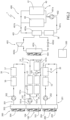
Figure 1 is a block diagram of a work vehicle according to a first embodiment of the present invention and with parts removed for clarity; -
Figure 2 is a block diagram of a portion of the work vehicle ofFigure 1 ; -
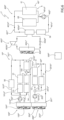
Figure 3 is a block diagram of a portion of a work vehicle according to a second embodiment of the present invention; -
Figure 4 is a block diagram of a portion of a work vehicle according to a third embodiment of the present invention; -
Figure 5 is a block diagram of a portion of a work vehicle according to a fourth embodiment of the present invention; and -
Figure 6 is a block diagram of a portion of a work vehicle according to a fifth embodiment of the present invention. - With reference to
figure 1 ,numeral 1 schematically indicates a work vehicle, by way of example a telescopic handler. -
Work vehicle 1 comprises amain body 2 and locomotion means 3, such as wheels or tracks, which are adapted to movemain body 2 relative to a reference system. By way of example, the reference system is fixed to the ground. -
Work vehicle 1 further comprises athermal engine 4, such as an internal combustion engine, and anelectrical motor 5, which are adapted to generate mechanical power for operating locomotion means 3. In detail,work vehicle 1 comprises atransmission 7, which is adapted to transmit motion fromelectrical motor 5 to locomotion means 3. -
Work vehicle 1 also comprises electrical energy storage means 6 electrically connected toelectrical motor 5 and adapted to supply electrical energy toelectrical motor 5. In the embodiment shown, electrical energy storage means 6 comprise twobatteries -
Work vehicle 1 further comprises anelectrical generator 8, which is operatively connected tothermal engine 4 and electrically connected to electrical energy storage means 6.Generator 8 is adapted to convert at least part of the motive power ofthermal engine 4 into electric power, which may be stored into electrical energy storage means 6. - Furthermore,
work vehicle 1 comprises an on-board charger 57, which is electrically connected to energy storage means 6 and which is adapted to be electrically connected to the electric grid. - In detail,
work vehicle 1 is settable to: - a plug-in charging mode, wherein
work vehicle 1 is electrically connected to the electric grid and electrical energy storage means 6 are charged; - an electric mode, wherein
electrical motor 5 is adapted to supply mechanical energy to locomotion means 6 andthermal engine 4 is idle; and - a hybrid mode, wherein
electrical motor 5 is adapted to supply mechanical energy to locomotion means 6 andthermal engine 4 is adapted to supply mechanical energy togenerator 8. - Furthermore,
work vehicle 1 comprises one or more of aninverter 52 electrically connected togenerator 8, a hydraulic system, an air system configured to cool downthermal engine 4, aninverter 53 electrically connected toelectrical motor 5, ahydraulic pump motor 54, aninverter 55 electrically connected tohydraulic pump motor 54, a DC/DC converter 56. -
Work vehicle 1 also comprises afirst system 10 and asecond system 20 to be cooled down, which comprise each a plurality of components ofwork vehicle 1. - In general, each component to be cooled of
work vehicle 1 is preferably associated with a nominal cooling flow rate range, which is a range of the flow rate of a cooling fluid adapted to remove heat from the component without causing damages to the component. On the one hand, if a component is cooled down by a cooling flow rate that is greater than the maximum value of the nominal cooling flow rate range, the component may be overcooled; on the other hand, if a component is cooled down by a cooling flow rate that is lower than the minimum value of the nominal cooling flow rate range, the component may overheat. - Advantageously,
work vehicle 1 comprises afirst cooling assembly 100 and asecond cooling assembly 200, which are respectively configured to cool downfirst system 10 andsecond system 20.First cooling assembly 100 comprises acircuit 101 adapted to be crossed by a fluid, apump 102 configured to circulate the fluid withincircuit 101 and aheat exchanger 103.Second cooling assembly 200 comprises acircuit 201 adapted to be crossed by a fluid, apump 202 configured to circulate the fluid withincircuit 201 and a heat exchanger 203 (Figure 2 ). -
Pumps pump 102 and/or the flow rate of thefluid crossing pump 102 may be varied independently of the rotational speed ofpump 202 and/or the flow rate of thefluid crossing pump 202. -
Circuits first system 10 andsecond system 20. Accordingly, the fluid flowing through therespective circuit circuit - The fluid flowing within
circuit 101 may be equal to or different from the fluid flowing withincircuit 201. - Furthermore, in the embodiment shown,
heat exchangers -
Work vehicle 1 further comprises acontrol unit 500, which is configured to controlfirst cooling assembly 100 andsecond cooling assembly 200. In detail,control unit 500 is operatively connected topumps -
First cooling assembly 100 also comprises afan 104, which is adapted to increase the kinetic energy of the air impingingfirst heat exchanger 103 andsecond cooling assembly 200 comprises afan 204, which is adapted to increase the kinetic energy of the air impinging heat exchanger 203 (Figure 2 ). -
Fan 104 andfan 204 are operatively connected tocontrol unit 500 and controllable independently of each other. In detail, the rotational speed offan 104 andfan 204 are variable. -
First system 10 andsecond system 20 comprise each at least two components ofwork vehicle 1 having respective nominal flow rate ranges at least partially overlapping. In other words, the at least two components can be cooled down by a flow rate of the fluid flowing within therespective circuit same system - As shown in
Figure 2 ,first system 10 compriseshydraulic pump motor 54,electrical motor 5,transmission 7,inverter 53 andinverter 55 andsecond system 20 comprisesinverter 52 andgenerator 8. In other words,first cooling assembly 100 is adapted to cool downhydraulic pump motor 54,electrical motor 5,transmission 7,inverter 53 andinverter 55 andsecond cooling assembly 200 is adapted to cool downinverter 52 andgenerator 8. - In detail,
circuit 101 comprises: - a
branch 101d extending betweenheat exchanger 103 andpump 102; - a
branch 101a extending frompump 102 and adapted to guide the fluid in succession across or in proximity tohydraulic pump motor 54,electrical motor 5 andtransmission 7; - a
branch 101e extending frompump 102 and adapted to guide the fluid in succession across or in proximity toinverter 55 andinverter 53; - a
branch 101b, which fluidly connectsbranches heat exchanger 103. - In other words,
first cooling assembly 100 is adapted to cool downinverter 55 andinverter 53 in parallel tohydraulic pump motor 54,electrical motor 5 andtransmission 7. In addition,second cooling assembly 200 is adapted to cool downinverter 52 andgenerator 8 in series. -
Circuit 101 further comprises abranch 101c extending betweenbranch 101a andbranch 101b. In detail,branch 101c fluidly connectsbranch 101a tobranch 101b at a portion ofbranch 101a interposed between the stretch ofbranch 101a passing through or in proximity toelectrical motor 5 and the stretch ofbranch 101a passing through or in proximity totransmission 7. - First cooling
assembly 100 also comprises a by-pass valve 105, which is fluidly connected to bothbranch 101a andbranch 101c. In detail, by-pass valve 105 is fluidly interposed between the stretch ofbranch 101a passing through or in proximity toelectrical motor 5 and the stretch ofbranch 101a passing through or in proximity totransmission 7. - By-
pass valve 105 is settable to: - a first configuration, wherein it is adapted to allow the passage of the fluid from
pump 102 towardstransmission 7 alongbranch 101a and adapted to deny the passage of the fluid alongbranch 101c; or - a second configuration, wherein it is adapted to deny the passage of the fluid from
pump 102 towardstransmission 7 alongbranch 101a and adapted to allow the passage of the fluid alongbranch 101c. -
Control unit 500 is operatively connected to by-pass valve 105 and is configured to set by-pass valve 105 to the first configuration when a temperature oftransmission 7 is greater than a temperature threshold and to set by-pass valve 105 to the second configuration when the temperature oftransmission 7 is lower than the temperature threshold. In detail, the temperature oftransmission 7 shall mean a mean temperature oftransmission 7 or a temperature in proximity totransmission 7 or a temperature of a specific region or a specific component oftransmission 7. - Furthermore,
work vehicle 1 comprises athird system 30 and afourth system 40 to be cooled down, which comprise each a plurality of components ofwork vehicle 1. -
Work vehicle 1 also comprises athird cooling assembly 300 and afourth cooling assembly 400, which are respectively configured to cool downthird system 30 andfourth system 40.Third cooling assembly 300 comprises acircuit 301 adapted to be crossed by a fluid, apump 302 configured to circulate the fluid withincircuit 301 and aheat exchanger 303.Fourth cooling assembly 400 comprises acircuit 401 adapted to be crossed by a fluid, apump 402 configured to circulate the fluid withincircuit 401 and aheat exchanger 403. -
Pumps unit 500 and controllable independently of each other and independently ofpumps pumps -
Circuits third system 30 andfourth system 40. Accordingly, the fluid flowing through therespective circuit circuit - The fluid flowing within
circuit 301 may be equal to or different from the fluid flowing withincircuits - Furthermore, in the embodiment shown,
heat exchanger 303 is a radiator. -
Third cooling assembly 300 also comprises afan 304, which is adapted to increase the kinetic energy of the air impingingheat exchanger 303.Fan 304 is controllable independently offans 104, 204 (Figure 2 ). In detail,fan 304 is operatively connected to controlunit 500. - As shown in
Figure 2 ,third system 30 comprises DC/DC converter 56 and on-board charger 57. In detail,third cooling assembly 300 is adapted to cool down DC/DC converter 56 and on-board charger 57 in series. - In addition,
fourth system 40 comprises electrical energy storage means 6. In other words,fourth cooling assembly 400 is adapted to cool down electrical energy storage means 6. - In detail,
heat exchanger 403 is a chiller, which comprises, in turn, anevaporator 403a, acompressor 403b, acondenser 403c and athermal expansion valve 403d. In further detail, evaporator 403a is adapted to be crossed by the fluid flowing withincircuit 401. - As shown in
Figure 2 ,circuit 401 comprises: - a
branch 401a extending frompump 402 towardsbatteries - a
branch 401b extending betweenbranch 401a andheat exchanger 403; - a
branch 401c extending betweenheat exchanger 403 and pump 402. - In detail,
fourth cooling assembly 400 is adapted to undercool electrical energy storage means 6. In further detail,fourth cooling assembly 400 is adapted to cool downbatteries -
Fourth system 40 further comprises afan 404, which is adapted to increase the kinetic energy of theair impinging condenser 403c.Fan 404 is controllable independently offan fan 404 is operatively connected to controlunit 500. - Furthermore,
circuit 401 also comprises aheater 58, which is arranged atbranch 401c and adapted to increase the temperature of the fluid flowing thoughcircuit 401.Heater 58 is operatively connected to controlunit 500. - Preferably but not necessarily,
heat exchangers heat exchanger 103 is interposed betweenheat exchanger 203 andheat exchanger 303. - Furthermore,
control unit 500 is configured to activatepump 202 and/orfan 204 whenwork vehicle 1 is set to the hybrid mode and to deactivatepump 202 andfan 204 whenwork vehicle 1 is set to the plug-in charging mode or the electric mode. -
Control unit 500 is also configured to activatepump 302 andfan 304 and to deactivatepumps work vehicle 1 is set to the plug-in charging mode. In addition, preferably,control unit 500 is also configured to deactivatefans work vehicle 1 is set to the plug-in charging mode. - When
work vehicle 1 is set to the hybrid mode,control unit 500 is configured to activatecooling assemblies work vehicle 1 is set to the plug-in charging mode,control unit 500 is configured to activatecooling assembly 300 and to deactivatecooling assemblies work vehicle 1 is set to the electric mode,control unit 500 is configured to activatecooling assemblies cooling assembly 200. The expression "activating a cooling assembly" means activating the pump(s) and/or the fan(s) of the relative cooling assembly. The expression "activating a pump" means commanding the pump to transfer energy to the fluid; the expression "activating a fan" means driving the fan in rotation. - Preferably,
control unit 500 is configured to activatecooling assembly 300 as soon aswork vehicle 1 is started, i.e., as soon aselectrical motor 5 and/orthermal engine 4 are turned on or any electric or electronic device ofwork vehicle 1 is switched on. More preferably,control unit 500 is configured to activatecooling assembly 300 as soon aswork vehicle 1 is started, even ifwork vehicle 1 is stationary with respect to the reference system. This allows DC/DC converter 56 to be cooled under all operating modes ofwork vehicle 1. -
Control unit 500 is further configured to: - activate
pump 402 and chiller 403 (in particular,compressor 403b and fan 404), when a temperature of electrical energy storage means 6 is greater than a first temperature threshold; and - deactivate
pump 402 andchiller 403 and/or activatingheater 58 when the temperature of electrical energy storage means 6 is lower than a second temperature threshold, which is lower than the first temperature threshold. - By way of example, the temperature of electrical energy storage means is a temperature of
battery 60 and/orbattery 61. - The operation of
work vehicle 1 according to the present invention is described in the following. - In use, when
work vehicle 1 is set to the hybrid mode, locomotion means 6 receive mechanical power fromelectrical motor 5,thermal engine 4 recharges electrical energy storage means 6 by means ofgenerator 8 andcontrol unit 500 activates coolingassemblies - In detail,
control unit 500 activatespump 102 andfan 104 and the fluid contained withincircuit 101 flows frompump 102 alongbranches branch 101e, it cools downinverter 55 andinverter 53; when the fluid flows alongbranch 101a, it cools downhydraulic pump motor 54 andelectric motor 5. In addition, if the temperature oftransmission 7 is greater than the temperature threshold,control unit 500 sets by-pass valve 105 to the first configuration and the fluid also cools downtransmission 7; if the temperature oftransmission 7 is lower than the temperature threshold,control unit 500 sets by-pass valve 105 to the second configuration and the fluid flows throughbranch 101c, thus impeding the cooling oftransmission 7. - At the same time,
control unit 500 activatespump 202 andfan 204 and the fluid contained withincircuit 201 cools downinverter 52 andgenerator 8. In addition,control unit 500 activatespump 302 andfan 304 and the fluid contained withincircuit 301 cools down DC/DC converter 56 and on-board charger 57. - When
work vehicle 1 is set to the plug-in charging mode,work vehicle 1 is stationary relative to the reference system, on-board charger 57 recharges electrical energy storage means 6, andcontrol unit 500 activates coolingassembly 300 and deactivates coolingassemblies - When
work vehicle 1 is set to the electric mode,electrical motor 5 operates locomotion means 6,thermal engine 4 is idle andcontrol unit 500 activates coolingassemblies assembly 200. - At the same time,
control unit 500 activatespump 402 andchiller 403, when the temperature of electrical energy storage means 6 is greater than the first temperature threshold and deactivates pump 402 andchiller 403 and/or activatesheater 58 when the temperature of electrical energy storage means 6 is lower than the second temperature threshold. - With reference to
Figure 3 ,1 I denotes a work vehicle according to a second embodiment of the present invention.Work vehicle 1I is similar to workvehicle 1 and will be described hereinafter only insofar as it differs therefrom; equal or equivalent parts ofwork vehicles 1; 1I will be marked, where possible, by the same reference numerals. -
Work vehicle 1I differs fromwork vehicle 1 in that it does not comprise a fourth system and a fourth cooling assembly. - In detail,
third system 30I comprises DC/DC converter 56, on-board charger 57 and electrical energy storage means 6. In other words,third cooling assembly 300I is adapted to cool down not only DC/DC converter 56 and on-board charger 57, but also electrical energy storage means 6. - Moreover,
third cooling assembly 300I comprises achiller 4030, which analogously tochiller 403, comprises anevaporator 4030a, acompressor 4030b, a condenser 4030c and athermal expansion valve 4030d. In further detail, evaporator 4030a is adapted to be crossed by the fluid flowing withincircuit 301I. - As shown in
Figure 3 ,circuit 301I comprises: - a
branch 301aI extending frompump 302I towards battery 60 (i.e., adapted to guide the fluid across or in proximity to battery 60); - a
branch 301bI extending frompump 302I towards battery 61 (i.e., adapted to guide the fluid across or in proximity to battery 61); - a
branch 301cI extending frompump 302I towards DC/DC on-board charger 57 and DC/DC converter 56 (i.e., adapted to guide the fluid across or in proximity to on-board charger 57 and DC/DC converter 56). - In detail,
chiller 4030 is adapted to undercool electrical energy storage means 6. -
Chiller 4030 further comprises afan 4040, which is adapted to increase the kinetic energy of the air impinging heat exchanger 4030c.Fan 4040 is controllable independently offan fan 4040 is operatively connected to controlunit 500I. - Furthermore,
circuit 301I also comprisesheater 58. - Preferably,
control unit 500I is configured to activatecooling assembly 300I as soon aswork vehicle 1I is started, even ifwork vehicle 1 is stationary. -
Cooling assembly 300I further comprises a three-way valve 305I, which is operatively connected to controlunit 500I and is settable to: - a first configuration, wherein it is adapted to allow the passage of the fluid deriving from
pump 302I towardsheat exchanger 303I; or - a second configuration, wherein it is adapted to deny the passage of the fluid from
pump 302I towardsheat exchanger 303I and to allow the passage of the fluid frompump 302I towardschiller 4030. -
Circuit 301I further comprises: - a
branch 301dI extending frombranches - a branch 301eI fluidly connecting
branches - a branch 301fI fluidly connecting three-way valve 305I to
heat exchanger 303I; - a
branch 301gI fluidly connectingheat exchanger 303I tochiller 4030; and - a
branch 301hI fluidly connecting three-way valve 305I tobranch 301gI. - In detail, when three-way valve 305I is set to the first configuration, it is adapted to allow the passage of the fluid from branch 301eI towards branch 301fI and to deny the passage of the fluid from branch 301eI towards
branch 301hI; when three-way valve 305I is set to the second configuration, it is adapted to deny the passage of the fluid from branch 301eI towards branch 301fI and to allow the passage of the fluid from branch 301eI towardsbranch 301hI. - Preferably, when the environmental temperature is lower than a temperature threshold (e.g., a temperature greater than but close to preferred operating temperature of
batteries 60 and 61),control unit 500I is configured to activatefan 304I, to deactivate or to keep deactivatedchiller 4030 and to set three-way valve 305I to the first configuration. In this way,batteries DC converter 56 and on-board charger 57 may be cooled down without the intervention ofcompressor 4030b. - Furthermore, when environmental temperature is greater than the temperature threshold,
control unit 500I is configured to deactivatefan 304I, to activatechiller 4030 and to set three-way valve 305I to the second configuration. This prevents theheat exchanger 303I from heating the fluid circulating in thecircuit 301I. -
Control unit 500I may also configured to activate simultaneously bothfan 304I andchiller 4030 and to set three-way valve 305I to the first configuration. - In detail, the environmental temperature is the temperature of the air surrounding
work vehicle 1I or electrical energy storage means 6 orheat exchanger 303I. - The operation of and
work vehicle 1I according to the present invention is similar to the operation ofwork vehicle 1 and the description thereof will be omitted for the sake of conciseness. - With reference to
Figure 4 ,1 II denotes a work vehicle according to a third embodiment of the present invention.Work vehicle 1II is similar to workvehicle 1 and will be described hereinafter only insofar as it differs therefrom; equal or equivalent parts ofwork vehicles 1; 1II will be marked, where possible, by the same reference numerals. -
Work vehicle 1II differs fromwork vehicle 1 in that it does not comprise the third system and the third cooling assembly. - In addition,
second system 20II comprises DC/DC converter 56 and on-board charger 57, in addition toinverter 52 andgenerator 8. In detail,second cooling assembly 200II is adapted to cool down insuccession converter 56, on-board charger 57,inverter 52 andgenerator 8. In further detail, the nominal flow rate ranges of DC/DC converter 56, on-board charger 57,inverter 52 andgenerator 8 at least partially overlap. - Preferably,
control unit 500II is configured to activatecooling assembly 200II as soon aswork vehicle 1II is started, even ifwork vehicle 1II is stationary. - Furthermore, when
work vehicle 1II is set to the hybrid mode or the electric mode,control unit 500II is configured to activate both coolingassemblies work vehicle 1II is set to the plug-in charging mode,control unit 500II is configured to activatecooling assembly 200II and to deactivatecooling assembly 100II. - The operation of and
work vehicle 1II according to the present invention is similar to the operation ofwork vehicle 1 and the description thereof will be omitted in the following for the sake of conciseness. - With reference to
Figure 5 ,1 III denotes a work vehicle according to a fourth embodiment of the present invention.Work vehicle 1III is similar to workvehicle 1 and will be described hereinafter only insofar as it differs therefrom; equal or equivalent parts ofwork vehicles 1; 1III will be marked, where possible, by the same reference numerals. -
Work vehicle 1III differs fromwork vehicle 1 in thatsecond system 20III comprises on-board charger 57, in addition toinverter 52 andgenerator 8. In addition,circuit 201III comprises: - a
branch 201dIII extending betweenheat exchanger 203III and pump 202III; - a
branch 201aIII extending frompump 202III and adapted to guide the fluid in succession across or in proximity togenerator 8 andinverter 52; - a branch 201eIII extending from
pump 202III and adapted to guide the fluid across on in proximity to on-board charger 57; and - a
branch 201bIII, which fluidly connectsbranches 201aIII e 201eIII toheat exchanger 203III. - Furthermore,
second cooling assembly 200III comprises a three-way valve 205III, which is settable to: - a first configuration, wherein it is adapted to allow the passage of the fluid from
pump 202III towardsgenerator 8 andinverter 52 alongbranch 201aIII and adapted to deny the passage of the fluid along branch 201eIII; or - a second configuration, wherein it is adapted to deny the passage of the fluid from
pump 202III towardsgenerator 8 andinverter 52 alongbranch 201aIII and adapted to allow the passage of the fluid along branch 201eIII towards on-board charger 57. - In addition,
third system 30III comprises DC/DC converter 56 only and does not comprise on-board charger 57. - Furthermore, when
work vehicle 1III is set to the hybrid mode,control unit 500III is configured to activatecooling assemblies way valve 205III to the first configuration; whenwork vehicle 1III is set to the plug-in charging mode,control unit 500 is configured to activatecooling assemblies cooling assembly 100III and to set the three-way valve 205III to the second configuration; whenwork vehicle 1III is set to the electric mode,control unit 500III is configured to activatecooling assemblies cooling assembly 200. - Preferably,
control unit 500III is configured to activatecooling assembly 300III as soon aswork vehicle 1III is started. More preferably,control unit 500III is configured to activatecooling assembly 300III as soon aswork vehicle 1III is started, even ifwork vehicle 1III is stationary. - The operation of and
work vehicle 1III according to the present invention is similar to the operation ofwork vehicle 1 and the description thereof will be omitted in the following for the sake of conciseness. - With reference to
Figure 6 ,1 IV denotes a work vehicle according to a fifth embodiment of the present invention.Work vehicle 1IV is similar to workvehicle 1 and will be described hereinafter only insofar as it differs therefrom; equal or equivalent parts ofwork vehicles 1; 1IV will be marked, where possible, by the same reference numerals. -
Work vehicle 1IV differs fromwork vehicle 1 in that it does not comprise the third system and the third cooling assembly. - Furthermore,
first system 10IV comprises DC/DC converter 56, in addition toinverter 55,inverter 53,hydraulic pump motor 54,electrical motor 5 andtransmission 7. In detail,circuit 101IV comprises a branch 101fIV extending frompump 102IV and adapted to guide the fluid across on in proximity to DC/DC converter 56. In addition,branch 101bIV fluidly connectsbranches heat exchanger 103IV. -
Second system 20IV comprises on-board charger 57, in addition toinverter 52 andgenerator 8, andcircuit 201IV comprises: - a
branch 201dIV extending betweenheat exchanger 203IV and pump 202IV; - a
branch 201aIV extending frompump 202IV and adapted to guide the fluid in succession across on in proximity toinverter 52 andgenerator 8; - a branch 201eIV extending from
pump 202IV and adapted to guide the fluid across on in proximity to on-board charger 57; and - a
branch 201bIV, which fluidly connectsbranches 201aIV e 201eIV toheat exchanger 203IV. - Furthermore,
second cooling assembly 200IV comprises a three-way valve 205IV, which is settable to: - a first configuration, wherein it is adapted to allow the passage of the fluid from
pump 202IV towardsgenerator 8 andinverter 52 alongbranch 201aIV and adapted to deny the passage of the fluid along branch 201eIV; or - a second configuration, wherein it is adapted to deny the passage of the fluid from
pump 202IV towardsgenerator 8 andinverter 52 alongbranch 201aIV and adapted to allow the passage of the fluid along branch 201eIV towards on-board charger 57. - Furthermore, when
work vehicle 1IV is set to the hybrid mode,control unit 500IV is configured to activatecooling assemblies way valve 205III to the first configuration; whenwork vehicle 1IV is set to the plug-in charging mode,control unit 500 is configured to activatecooling assemblies way valve 205IV to the second configuration; whenwork vehicle 1III is set to the electric mode,control unit 500IV is configured to activatecooling assembly 100IV and to deactivatecooling assembly 200IV. - Preferably,
control unit 500V is configured to activatecooling assembly 100IV as soon aswork vehicle 1IV is started, even ifwork vehicle 1IV is stationary. - The operation of and
work vehicle 1IV according to the present invention is similar to the operation ofwork vehicle 1 and the description thereof will be omitted in the following for the sake of conciseness. - The invention further relates to a method of controlling
work vehicle 1; 1I; 1II; IIII; 1IV comprising the step of controllingpump 102; 102I; 102II; 102III; 102IV and pump 202; 202I; 202II; 202III; 202IV independently of each other by means ofcontrol unit 500; 500I; 500II; 500III; 500IV. - The method further comprises the step of controlling
fan 104; 104I; 104II; 104III; 104IV andfan 204; 204I; 204II; 204III; 204IV independently of each other by means ofcontrol unit 500; 500I; 500II; 500III; 500IV. - The method also comprises the step of activating
pump 202; 202I; 202III; 202IV and/orfan 204; 204I; 204III; 204IV whenwork vehicle 1; 1I; IIII; 1IV is set to the hybrid mode and to deactivatesecond pump 202; 202I; 202III; 202IV and/orsecond fan 204; 204I; 204III; 204IV whenwork vehicle 1; 1I; IIII; 1IV is set to the plug-in charging mode or the electric mode. - The method also comprises the step of controlling
pump 302 and pump 402 independently of each other and independently ofpumps - The method also comprises the step of controlling
pump 302I; 302III independently ofpumps 102I; 102III and 202I; 202III. - The method also comprises the step of activating
pump 302 and/orfan 304 and to deactivatepumps fans work vehicle 1 is set to the plug-in charging mode. - The method also comprises the step of activating
fan 304I, of deactivatingchiller 4030 and of setting three-way valve 305I to the first configuration, by means ofcontrol unit 500I, when the environmental temperature is lower than the temperature threshold; and the step of deactivatingfan 304I, of activatingchiller 4030 and of setting three-way valve 305I to the second configuration, when the environmental temperature is greater than the temperature threshold. - In view of the foregoing, the advantages of
work vehicle 1; 1I; 1II; 1III; 1IV and the related control method according to the invention are apparent. - In particular, since
work vehicle 1; 1I; 1II; IIII; 1IV comprises at least twodifferent cooling assemblies 100; 100I; 100II; 100III; 100IV, 200; 200I; 200II; 200III; 200IV, which are independently controllable of one another, the total amount of electrical power required to cool the components to be cooled of the work vehicle is optimized. In particular, the number of components that are cooled when cooling is not needed is minimized. As a result, the amount of electrical energy available to be used onboard work vehicle 1; 1I; 1II; 1III; 1IV is maximized. - It is clear that modifications can be made to work
vehicle 1; 1I; 1II; 1III; 1IV and the related control method which do not extend beyond the scope of protection defined by the claims. - In particular,
first system 10; 10I; 10II; 10III; 10IV,second system 20; 20I; 20II; 20III; 20IV,third system 30; 30I; 30III and/orfourth system 40; 40II; 40III; 40IV may share one or more components. In other words, one or more components to be cooled down ofwork vehicle 1; 1I; 1II; IIII; 1IV may be adapted to be cooled down by more than one offirst cooling assembly 100; 100I; 100II; 100III; 100IV,second cooling assembly 200; 200I; 200II; 200III; 200IV,third cooling assembly 300; 300I; 300III andfourth system 400; 400II; 400III; 400IV. - Electrical energy storage means 6 may comprise only one
battery - First system, second system, third system and/or fourth system may comprise one or more of
thermal engine 4,generator 8,inverter 52, hydraulic system, air system,transmission 7,inverter 53,hydraulic pump motor 54,inverter 55, DC/DC converter 56, electrical energy storage means 6 and on-board charger 57. - According to a not-shown embodiment, when
work vehicle 1; 1I; 1II; 1III; 1IV is set to the hybrid mode, bothelectrical motor 5 andthermal engine 4 are adapted to supply mechanical energy to locomotion means 6.
Claims (18)
- Work vehicle (1; 1I; 1II; 1III; 1IV) comprising:- a main body (2);- locomotion means (3) adapted to move said main body (2) relative to a reference system;- a thermal engine (4) and an electrical motor (5), which are adapted to generate mechanical power;- electrical energy storage means (6) electrically connected to said electrical motor (5);- a control unit (500; 500I; 500II; 500III; 500IV) ;- a first system (10; 10I; 10II; 10III; 10IV) and a second system (20; 20I; 20II; 20III; 20IV) to be cooled down, in use;- a first cooling assembly (100; 100I; 100II; 100III; 100IV) and a second cooling assembly (200; 200I; 200II; 200III; 200IV), which are respectively configured to cool down said first system (10; 10I; 10II; 10III; 10IV) and said second system (20; 20I; 20II; 20III; 20IV);said first cooling assembly (100; 100I; 100II; 100III; 100IV) comprising:- a first circuit (101; 10II; 10III; 101III; 101IV), which is adapted to be crossed by a first fluid;- at least one first pump (102; 102I; 102II; 102III; 102IV) configured to circulate said first fluid within said first circuit (101; 10II; 10III; 101III; 101IV) ; and- at least one first heat exchanger (103; 103I; 103II; 103III; 103IV);said second cooling assembly (200; 200I; 200II; 200III; 200IV) comprising:- a second circuit (201; 20II; 20III; 201III; 201IV), which is adapted to be crossed by a second fluid;- at least one second pump (202; 202I; 202II; 202III; 202IV) configured to circulate said second fluid within said second circuit (201; 201I; 201II; 201III; 201IV); and- at least one second heat exchanger (203; 203I; 203II; 203III; 203IV) ;said control unit (500; 500I; 500II; 500III; 500IV) being configured to control, in use, said first pump (102; 102I; 102II; 102III; 102IV) and said second pump (202; 202I; 202II; 202III; 202IV) independently of each other.
- Work vehicle according to claim 1, wherein said work vehicle (1; 1I; 1II; IIII; 1IV) is settable to:- a plug-in charging mode, wherein said electrical energy storage means (6) are charged, in use;- an electric mode, wherein said electrical motor (5) is operatively connected to said locomotion means (6) and said thermal engine (4) is idle, in use; and- a hybrid mode, wherein said electrical motor (5) and said thermal engine (4) are adapted to at least indirectly supply said locomotion means (6) with mechanical power.
- Work vehicle according to claim 1 or 2, wherein said first cooling assembly (100; 100I; 100II; 100III; 100IV) comprises a first fan (104; 104I; 104II; 104III; 104IV), which is adapted to increase the kinetic energy of the air impinging, in use, said first heat exchanger (103; 103I; 103II; 103III; 103IV) and/or said second cooling assembly (200; 200I; 200II; 200III; 200IV) comprises a second fan (204; 204I; 204II; 204III; 204IV), which is adapted to increase the kinetic energy of the air impinging, in use, said second heat exchanger (203; 203I; 203II; 203III; 203IV) ;
said control unit (500; 500I; 500II; 500III; 500IV) being configured to control said first fan (104; 104I; 104II; 104III; 104IV) and said second fan (204; 204I; 204II; 204III; 204IV) independently of each other. - Work vehicle according to any one of the foregoing claims, wherein said first system (10; 10I; 10II; 10III; 10IV) and said second system (20; 20I; 20II; 20III; 20IV) each comprise one or more components of said work vehicle (1; 1I; 1II; IIII; 1IV); each said component being associated with a respective nominal cooling flow rate range, which is a range of the flow rate of said respective first or second fluid adapted to remove heat, in use, from said component without causing damages;wherein when said first system (10; 10I; 10II; 10III; 10IV) comprises more than one component of said work vehicle (1; 1I; 1II; 1III; 1IV), the components of said first system (10; 10I; 10II; 10III; 10IV) have respective nominal flow rate ranges at least partially overlapping;wherein when said second system (20; 20I; 20II; 20III; 20IV) comprises more than one component of said work vehicle (1; 1I; 1II; 1III; 1IV), the components of said second system (20; 20I; 20II; 20III; 20IV) have respective nominal flow rate ranges at least partially overlapping.
- Work vehicle according to any one of the foregoing claims, further comprising one or more of the following:- a generator (8) operatively connected to said thermal engine (4) and electrically connected to said electrical energy storage means (6);- a first inverter (52) electrically connected to said generator (8);- a hydraulic system;- an air system configured to cool down, in use, said thermal engine (4);- a transmission (7), which operatively connects said thermal engine (4) and/or said electrical motor (5) to said locomotion means (3);- a second inverter (53) electrically connected to said electrical motor (5);- a hydraulic pump motor (54);- a third inverter (55) electrically connected to said hydraulic pump motor (54);- a DC/DC converter (56);- an on-board charger (57) electrically connected to said electrical energy storage means (6).
- Work vehicle according to claim 5, wherein said first system (10; 10I; 10II; 10III; 10IV) and said second system (20; 20I; 20II; 20III; 20IV) each comprise one or more of said thermal engine (4), generator (8), first inverter (52), hydraulic system, air system, transmission (7), second inverter (53), hydraulic pump motor (54), third inverter (55), DC/DC converter (56), electrical energy storage means (6) and on-board charger (57).
- Work vehicle according to claim 5, wherein said first system (10; 10I) comprises said hydraulic pump motor (54), said electrical motor (5), said transmission (7), said second inverter (53) and said third inverter (55);
said second system (20; 20I) comprising said first inverter (52) and said generator (8). - Work vehicle according to claim 5, wherein said first system (10II) comprises said hydraulic pump motor (54), said electrical motor (5), said transmission (7), said second inverter (53) and said third inverter (55);
said second system (20II) comprising said first inverter (52), said generator (8), said DC/DC converter (56) and said on-board charger (57). - Work vehicle according to claim 5, wherein said first system (10III) comprises said hydraulic pump motor (54), said electrical motor (5), said transmission (7), said second inverter (53) and said third inverter (55);said second system (20III) comprising said first inverter (52), said generator (8) and said on-board charger (57);said second cooling assembly (200III) comprising a first three-way valve (205III), which is settable to:- a first configuration, wherein it is adapted to allow, in use, the passage of said second fluid from said second pump (202III) towards said generator (8) and said inverter (52) and to deny the passage of said second fluid towards said on-board charger (57); or- a second configuration, wherein it is adapted to deny, in use, the passage of said second fluid from said second pump (202III) towards said generator (8) and said inverter (52) and to allow the passage of said second fluid towards said on-board charger (57).
- Work vehicle according to claim 5, wherein said first system (10IV) comprises said hydraulic pump motor (54), said electrical motor (5), said transmission (7), said second inverter (53), said third inverter (55) and said DC/DC converter (56);said second system (20IV) comprising said first inverter (52), said generator (8) and said on-board charger (57);said second cooling assembly (200IV) comprising a first three-way valve (205IV), which is settable to:- a first configuration, wherein it is adapted to allow, in use, the passage of said second fluid from said second pump (202IV) towards said generator (8) and said inverter (52) and to deny the passage of said second fluid towards said on-board charger (57); or- a second configuration, wherein it is adapted to deny, in use, the passage of said second fluid from said second pump (202IV) towards said generator (8) and said inverter (52) and to allow the passage of said second fluid towards said on-board charger (57).
- Work vehicle according to any one of claim 7 to 10, wherein said first circuit (101; 10II; 10III; 101III; 101IV) comprises:- a first branch (101a; 101aI; 101aII; 101aIII; 101aIV) extending from said first pump (102; 102I; 102II; 102III; 102IV) across or in proximity to said hydraulic pump motor (54), said electrical motor (5) and said transmission (7);- a second branch (101b; 101bI; 101bII; 101bIII; 101bIV) , which fluidly connects said first branch (101a; 101aI; 101aII; 101aIII; 101aIV) to said first heat exchanger (103; 103I; 103II; 103III; 103IV);- a third branch (101c; 101cI; 101cII; 101cIII; 101cIV) extending between said first branch (101a; 101aI; 101aII; 101aIII; 101aIV) and said second branch (101b; 101bI; 101bII; 101bIII; 101bIV) ; and- a by-pass valve (105; 105I; 105II; 105III; 105IV) , which is fluidly connected to said first branch (101a; 101aI; 101aII; 101aIII; 101aIV) and said third branch (101c; 101cI; 101cII; 101cIII; 101cIV);wherein said by-pass valve (105; 105I; 105II; 105III; 105IV) is settable to:- a first configuration, wherein it allows the passage of said first fluid from said first pump (102; 102I; 102II; 102III; 102IV) towards said transmission (7) along said first branch (101a; 101aI; 101aII; 101aIII; 101aIV) and denies the passage of said first fluid along said third branch (101c; 101cI; 101cII; 101cIII; 101cIV); or- a second configuration, wherein it denies the passage of said first fluid from said first pump (102; 102I; 102II; 102III; 102IV) towards said transmission (7) along said first branch (101a; 101aI; 101aII; 101aIII; 101aIV) and allows the passage of said first fluid along said third branch (101c; 101cI; 101cII; 101cIII; 101cIV).
- Work vehicle according to any one of claims 2, 3 and any one of claims 7 or 11 when depending on claim 7, wherein said control unit (500; 500I) is configured to activate said second pump (202; 202I) and/or said second fan (204; 204I) when said work vehicle (1; 1I) is set, in use, to said hybrid mode and to deactivate said second pump (202; 202I) and/or said second fan (204; 204I) when said work vehicle (1; 1I) is set, in use, to said plug-in charging mode or said electric mode.
- Work vehicle according to claim 7, or claim 11 when depending on claim 7, or claim 12 when depending on claim 7, further comprising:- a third system (30) and a fourth system (40) to be cooled down;- a third cooling assembly (300) and a fourth cooling assembly (400), which are respectively configured to cool down said third system (30) and said fourth system (40);said third cooling assembly (300) comprising:- a third circuit (301), which is adapted to be crossed by a third fluid;- at least one third pump (302) configured to circulate said third fluid within said third circuit (301); and- at least one third heat exchanger (303);said fourth cooling assembly (400) comprising:- a fourth circuit (401), which is adapted to be crossed by a fourth fluid;- at least one fourth pump (402) configured to circulate said fourth fluid within said fourth circuit (401); and- at least one fourth heat exchanger (403);said control unit (500) being configured to control said third pump (302) and said fourth pump (402) independently of each other and independently of said first and second pumps (102, 202);said third system (30) comprising said DC/DC converter (56) and said on-board charger (57);said fourth system (40) comprising said electrical energy storage means (6).
- Work vehicle according to claim 7 or claim 11 when depending on claim 7 or claim 12 when depending on claim 7, further comprising a third system (30I) to be cooled down and a third cooling assembly (300I) configured to cool down said third system (30I);said third cooling assembly (300I) comprising:- a third circuit (301I), which is adapted to be crossed by a third fluid;- at least one third pump (302I) configured to circulate said third fluid within said third circuit (301I); and- at least one third heat exchanger (303I);said control unit (500) being configured to control said third pump (302I) independently of said first and second pumps (102I, 202I) ;said third system (30I) comprising said DC/DC converter (56), said on-board charger (57) and said electrical energy storage means (6).
- Work vehicle according to claims 2, 3 and 13, wherein said third cooling assembly (300) comprises a third fan (304), which is adapted to increase the kinetic energy of the air impinging, in use, said third heat exchanger (303);
wherein said control unit (500) is configured to activate said third pump (302) and/or said third fan (304) and to deactivate said first and second pumps (102, 202) and/or said first and second fans (104, 204) when said work vehicle (1) is set, in use, to said plug-in charging mode. - Work vehicle according to claims 2, 3 and 14, wherein said third cooling assembly (300I) comprises:- a third fan (304I), which is adapted to increase the kinetic energy of the air impinging, in use, said third heat exchanger (303I);- a chiller (4030), which is adapted to cool down, in use, said third fluid;said third cooling assembly (300I) further comprising a second three-way valve (305I), which is settable to:- a first configuration, wherein it is adapted to allow the passage of said third fluid from said third pump (302I) to said third heat exchanger (303I); or- a second configuration, wherein it is adapted to deny the passage of said third fluid from said third pump (302I) to said third heat exchanger (303I) and to allow the passage of said third fluid from said third pump (302I) towards said chiller (4030).wherein when an environmental temperature is lower than a temperature threshold, said control unit (500I) is configured to activate, in use, said third fan (304I), to deactivate said chiller (4030) and to set said second three-way valve (305I) to said first configuration; when said environmental temperature is greater than said temperature threshold, said control unit (500I) is configured to deactivate, in use, said third fan (304I), to activate said chiller (4030) and to set said second three-way valve (305I) to said second configuration.
- Work vehicle according to claim 9 or claim 11 when depending on claim 9, further comprising a third system (30III) to be cooled down and a third cooling assembly (300III) configured to cool down said third system (30III);said third cooling assembly (300III) comprising:- a third circuit (301III), which is adapted to be crossed by a third fluid;- at least one third pump (302III) configured to circulate said third fluid within said third circuit (301III); and- at least one third heat exchanger (303III);said control unit (500III) being configured to control said third pump (302III) independently of said first and second pumps (102III; 202III) ; said third system (30III) comprising said DC/DC converter (56).
- Method of controlling a work vehicle (1; 1I; 1II; 1III; 1IV) according to any one of the foregoing claims; said method comprising the step i) of controlling said first pump (102; 102I; 102II; 102III; 102IV) and said second pump (202; 202I; 202II; 202III; 202IV) independently of each other.
Applications Claiming Priority (1)
| Application Number | Priority Date | Filing Date | Title |
|---|---|---|---|
| IT102023000010380A IT202300010380A1 (en) | 2023-05-23 | 2023-05-23 | WORK VEHICLE WITH AN IMPROVED THERMAL LAYOUT AND RELATED CONTROL METHOD |
Publications (2)
| Publication Number | Publication Date |
|---|---|
| EP4467786A1 true EP4467786A1 (en) | 2024-11-27 |
| EP4467786B1 EP4467786B1 (en) | 2026-05-06 |
Family
ID=87280272
Family Applications (1)
| Application Number | Title | Priority Date | Filing Date |
|---|---|---|---|
| EP24177167.4A Active EP4467786B1 (en) | 2023-05-23 | 2024-05-21 | Work vehicle with an improved thermal layout and a control method thereof |
Country Status (2)
| Country | Link |
|---|---|
| EP (1) | EP4467786B1 (en) |
| IT (1) | IT202300010380A1 (en) |
Citations (4)
| Publication number | Priority date | Publication date | Assignee | Title |
|---|---|---|---|---|
| US20040045749A1 (en) * | 2002-09-06 | 2004-03-11 | Ford Global Technologies, Inc. | Cooling system and method for a hybrid electric vehicle |
| US20050274507A1 (en) * | 2004-06-10 | 2005-12-15 | Denso Corporation | Cooling system used for hybrid-powered automobile |
| EP3176334A1 (en) * | 2014-07-28 | 2017-06-07 | Hitachi Construction Machinery Co., Ltd. | Hybrid-type work machine |
| EP3686352A1 (en) * | 2017-09-21 | 2020-07-29 | Hitachi Construction Machinery Co., Ltd. | Hybrid-type work machine |
-
2023
- 2023-05-23 IT IT102023000010380A patent/IT202300010380A1/en unknown
-
2024
- 2024-05-21 EP EP24177167.4A patent/EP4467786B1/en active Active
Patent Citations (4)
| Publication number | Priority date | Publication date | Assignee | Title |
|---|---|---|---|---|
| US20040045749A1 (en) * | 2002-09-06 | 2004-03-11 | Ford Global Technologies, Inc. | Cooling system and method for a hybrid electric vehicle |
| US20050274507A1 (en) * | 2004-06-10 | 2005-12-15 | Denso Corporation | Cooling system used for hybrid-powered automobile |
| EP3176334A1 (en) * | 2014-07-28 | 2017-06-07 | Hitachi Construction Machinery Co., Ltd. | Hybrid-type work machine |
| EP3686352A1 (en) * | 2017-09-21 | 2020-07-29 | Hitachi Construction Machinery Co., Ltd. | Hybrid-type work machine |
Also Published As
| Publication number | Publication date |
|---|---|
| EP4467786B1 (en) | 2026-05-06 |
| IT202300010380A1 (en) | 2024-11-23 |
Similar Documents
| Publication | Publication Date | Title |
|---|---|---|
| US9096207B2 (en) | Hybrid vehicle powertrain cooling system | |
| CN111315609B (en) | Cooling system for motor vehicles and motor vehicle with such a cooling system | |
| US9844995B2 (en) | EV muti-mode thermal control system | |
| US12179558B2 (en) | Electric vehicle thermal management and safety apparatus | |
| KR101317120B1 (en) | Temperature control system for a drive device of a motor vehicle, method for operating such a temperature control system and motor vehicle having such a temperature control system | |
| CN102596603B (en) | Heat exchanger arrangement | |
| EP3088230A1 (en) | Electric vehicle multi-mode thermal control system | |
| KR102210358B1 (en) | Cooling system in hybrid vehicle | |
| US10069180B2 (en) | Thermoelectric battery cooling system and method | |
| EP3504408B1 (en) | A cooling system for an electric power unit in a vehicle | |
| CN111347931B (en) | Temperature adjustment loop and its control method | |
| JP5348063B2 (en) | Hybrid vehicle cooling system | |
| CN112825376A (en) | Battery temperature management device | |
| JP2021156234A (en) | Heat management device | |
| US20160318410A1 (en) | EV Muti-Mode Thermal Control System | |
| US11888139B2 (en) | Temperature adjustment circuit | |
| US10710470B2 (en) | Vehicular cooling system | |
| CN115476644B (en) | Vehicle thermal management system | |
| JP2020102380A (en) | Temperature adjusting circuit and control method thereof | |
| WO2015080659A1 (en) | Cooling system | |
| KR102600060B1 (en) | Valve module for cooling system of electric vehicle | |
| EP2643176B1 (en) | A thermal energy administration system | |
| US20040187505A1 (en) | Integrated cooling system | |
| EP4467786B1 (en) | Work vehicle with an improved thermal layout and a control method thereof | |
| JP2021146812A (en) | Heat management device |
Legal Events
| Date | Code | Title | Description |
|---|---|---|---|
| PUAI | Public reference made under article 153(3) epc to a published international application that has entered the european phase |
Free format text: ORIGINAL CODE: 0009012 |
|
| STAA | Information on the status of an ep patent application or granted ep patent |
Free format text: STATUS: THE APPLICATION HAS BEEN PUBLISHED |
|
| AK | Designated contracting states |
Kind code of ref document: A1 Designated state(s): AL AT BE BG CH CY CZ DE DK EE ES FI FR GB GR HR HU IE IS IT LI LT LU LV MC ME MK MT NL NO PL PT RO RS SE SI SK SM TR |
|
| STAA | Information on the status of an ep patent application or granted ep patent |
Free format text: STATUS: REQUEST FOR EXAMINATION WAS MADE |
|
| 17P | Request for examination filed |
Effective date: 20250527 |
|
| GRAP | Despatch of communication of intention to grant a patent |
Free format text: ORIGINAL CODE: EPIDOSNIGR1 |
|
| STAA | Information on the status of an ep patent application or granted ep patent |
Free format text: STATUS: GRANT OF PATENT IS INTENDED |
|
| RIC1 | Information provided on ipc code assigned before grant |
Ipc: F01P 3/20 20060101AFI20251125BHEP Ipc: F01P 3/12 20060101ALI20251125BHEP Ipc: F01P 7/16 20060101ALI20251125BHEP Ipc: B60K 11/02 20060101ALI20251125BHEP Ipc: B60W 20/00 20160101ALI20251125BHEP Ipc: E02F 9/00 20060101ALI20251125BHEP Ipc: B60K 6/46 20071001ALI20251125BHEP Ipc: B60K 11/04 20060101ALI20251125BHEP Ipc: B60W 10/30 20060101ALI20251125BHEP Ipc: B60W 30/184 20120101ALI20251125BHEP Ipc: B60K 11/06 20060101ALI20251125BHEP Ipc: B60K 1/00 20060101ALN20251125BHEP |
|
| INTG | Intention to grant announced |
Effective date: 20251208 |
|
| GRAS | Grant fee paid |
Free format text: ORIGINAL CODE: EPIDOSNIGR3 |
|
| GRAA | (expected) grant |
Free format text: ORIGINAL CODE: 0009210 |
|
| STAA | Information on the status of an ep patent application or granted ep patent |
Free format text: STATUS: THE PATENT HAS BEEN GRANTED |
|
| AK | Designated contracting states |
Kind code of ref document: B1 Designated state(s): AL AT BE BG CH CY CZ DE DK EE ES FI FR GB GR HR HU IE IS IT LI LT LU LV MC ME MK MT NL NO PL PT RO RS SE SI SK SM TR |
|
| REG | Reference to a national code |
Ref country code: CH Ref legal event code: F10 Free format text: ST27 STATUS EVENT CODE: U-0-0-F10-F00 (AS PROVIDED BY THE NATIONAL OFFICE) Effective date: 20260506 Ref country code: GB Ref legal event code: FG4D |
|
| REG | Reference to a national code |
Ref country code: DE Ref legal event code: R096 Ref document number: 602024004565 Country of ref document: DE |
|
| REG | Reference to a national code |
Ref country code: IE Ref legal event code: FG4D |
|
| PGFP | Annual fee paid to national office [announced via postgrant information from national office to epo] |
Ref country code: AT Payment date: 20260714 Year of fee payment: 3 |