EP4467732A1 - Water collection module - Google Patents
Water collection module Download PDFInfo
- Publication number
- EP4467732A1 EP4467732A1 EP23174924.3A EP23174924A EP4467732A1 EP 4467732 A1 EP4467732 A1 EP 4467732A1 EP 23174924 A EP23174924 A EP 23174924A EP 4467732 A1 EP4467732 A1 EP 4467732A1
- Authority
- EP
- European Patent Office
- Prior art keywords
- base element
- water
- holding
- hose
- water reservoir
- Prior art date
- Legal status (The legal status is an assumption and is not a legal conclusion. Google has not performed a legal analysis and makes no representation as to the accuracy of the status listed.)
- Pending
Links
Images


Classifications
-
- E—FIXED CONSTRUCTIONS
- E03—WATER SUPPLY; SEWERAGE
- E03B—INSTALLATIONS OR METHODS FOR OBTAINING, COLLECTING, OR DISTRIBUTING WATER
- E03B3/00—Methods or installations for obtaining or collecting drinking water or tap water
- E03B3/02—Methods or installations for obtaining or collecting drinking water or tap water from rain-water
- E03B3/03—Special vessels for collecting or storing rain-water for use in the household, e.g. water-butts
-
- A—HUMAN NECESSITIES
- A01—AGRICULTURE; FORESTRY; ANIMAL HUSBANDRY; HUNTING; TRAPPING; FISHING
- A01G—HORTICULTURE; CULTIVATION OF VEGETABLES, FLOWERS, RICE, FRUIT, VINES, HOPS OR SEAWEED; FORESTRY; WATERING
- A01G27/00—Self-acting watering devices, e.g. for flower-pots
- A01G27/02—Self-acting watering devices, e.g. for flower-pots having a water reservoir, the main part thereof being located wholly around or directly beside the growth substrate
-
- E—FIXED CONSTRUCTIONS
- E03—WATER SUPPLY; SEWERAGE
- E03B—INSTALLATIONS OR METHODS FOR OBTAINING, COLLECTING, OR DISTRIBUTING WATER
- E03B5/00—Use of pumping plants or installations; Layouts thereof
- E03B5/02—Use of pumping plants or installations; Layouts thereof arranged in buildings
- E03B5/025—Use of pumping plants or installations; Layouts thereof arranged in buildings with surface tanks
Definitions
- the present disclosure relates to a water collection module, and more particularly to a base element of a water collection module that may allow easy access of collected water.
- Water reservoirs and other devices are utilized for the purpose of collecting and storing water runoff from impervious surfaces such as the rooftops of dwellings. While generally unpotable, such systems provide a useful source of water for tasks such as irrigation, washing cars or driveways, and the like.
- the water reservoir are mounted on a base element to elevate the water reservoir for access to the water.
- the water is extracted from the water reservoir by opening a spigot provided near the bottom of the water reservoir and filling a container such as a watering can.
- a soaker hose may also be attached to the bottom of the water reservoir to water nearby plants.
- '976 reference provides a water collection module with a water reservoir mounted on top of a hollow base element. At the bottom of the water reservoir there is a water outlet to which various watering components may be fixed and which may then be housed inside a free space surrounded by the base element.
- the objective is at least partially achieved by a base element of a water collection module.
- the base element of the water collection module includes a bottom side.
- the base element also includes a top side, which is opposite to the bottom side, and connected to the bottom side via a side surface.
- the bottom side forms a base face for standing the base element on an underlying surface and the opposite side, i.e., the top side forms a mounting face to hold any other device, in particular a water reservoir, mounted to it.
- the base element is characterized in that a holding structure is formed inside the base element.
- the holding structure incorporates at least one holding pocket for removably holding a watering accessory.
- the present disclosure provides an improved base element for the water reservoir.
- the base element may provide a certain height to the water reservoir relative to the underlying surface, which may allow easy access of the water stored in the water reservoir, for example by opening a tap provided proximate to a bottom of the water reservoir.
- the base element advantageously includes the holding structure incorporating at least one holding pocket.
- the at least one holding pocket allows to removably hold at least one watering accessory, which may be configured to transport water collected or stored in the water reservoir for various applications, such as, but not limited to, gardening, kitchen uses, household purposes, etc.
- the at least one watering accessory, which may be removably held in the at least one holding pocket may enable an easy and ergonomic access of the collected water.
- the at least one watering accessory may allow to access water from the water reservoir without changing structural orientation of the water collection module such as unmounting of the water reservoir from the top surface of the base element. This may save any extra effort or manpower to be used for accessing water. Further, the at least one holding pocket may allow removable holding of the at least one watering accessory in an organized and stable manner.
- the water collection module according to the present invention may denote an assembly of the water reservoir and the base element such that the water reservoir may be mounted on the base element.
- the base element may have a tapered cylinder, or frustum like shape.
- the base element may have any other shape and size without limiting the scope of the present invention.
- the base element and the holding structure are integrally formed.
- the base element and the holding structure may preferably be made from a plastic material and may be integrally formed by any means known in the art.
- the integral formation may prove to be cost-effective, fast, and simple way of manufacturing the base element and the holding structure.
- the at least one holding pocket may be formed using a plastic material by employing any manufacturing process such as, but not limited to, molding.
- the at least one holding pocket may be clipped or glued to the base element or may be integrally formed with the base element.
- the at least one holding pocket may be formed using foamed material that is connected to the base element.
- the foamed material may advantageously have benefits such as, but not limited to, thermal insulation, high strength per unit weight, and ease of molding.
- the at least one holding pocket may be able to soak in heat produced by the watering accessory held by the at least one holding pocket such that other watering accessories arranged nearby may continue their operation without any affect or influence of heat.
- the at least one holding pocket may for example be made from one or more of vinyls, polystyrene, polyethylene, phenolics, silicones, cellulose acetate, and urethanes.
- the at least one holding pocket may include at least one coupling cavity to allow fluid coupling between the various watering accessories removably held in the at least one holding pocket such that the watering accessories may be required to be fluidly coupled for allowing transport of the collected water for various applications.
- the watering accessory is formed by one of a pump and/or a hose and/or a hose reel.
- One or more watering accessories may be removably held or stored in the at least one holding pocket of the holding structure integrally formed with the base element. However, all the water accessories may or may not be required to be in operation simultaneously.
- the water accessories to be held or stored in the base element may be selected by a user based on current and future application requirements. For example, the user may store the pump in the base element, and a few years after may realize a need for the hose reel to be used in conjunction with the pump and then may store the hose reel as well in the base element and fluidly connect both the pump and the hose reel.
- the watering accessories such as the pump, the hose, and the hose reel may alone or together allow the user to have easy access of the water stored in the water reservoir for various industrial and domestic applications. Further, the watering accessory may be any water accessory other than the pump, the hose, and the hose reel as well.
- the holding structure incorporates the holding pocket for holding a water inlet.
- the water inlet is configured to receive water from the water reservoir.
- the water inlet may be fluidly connected or coupled to a water outlet of the water reservoir which may be provided at the bottom of the water reservoir.
- the water inlet may be a hose, which may be fluidly coupled to the water outlet of the water reservoir using, for example, a hose connector.
- the water inlet may be advantageously held in the holding pocket and may act as an interface between the water outlet of the water reservoir and the other watering accessories such as the pump, the hose, or the hose reel held in the holding structure of the based element.
- the holding structure incorporates the holding pocket for holding at least one tube or hose to transport water entering the base element via the water inlet.
- the water inlet may be fluidly connected with the at least one tube or hose held in the holding pocket of the holding structure.
- the at least one tube or hose may further be fluidly connected with the watering accessory, for example, the pump, or the hose reel held in an adjacent holding pocket such that the water received from the water inlet may be transferred to the watering accessory for to allow for easy access of the collected or stored water for the user.
- the base element includes an opening to access the watering accessory.
- the opening may be one or more openings formed on the side surface of the base element.
- the opening may allow, for example, a hose of the hose reel to be taken out and fluidly connect with a garden spray, and the like.
- the opening in the side surface of the base element may be formed by removing a separable part from the base element after purchase of the base element.
- the opening may be covered after use with a hinged door like structure without affecting the aesthetics of the base element.
- the opening in the side surface of the base element may be formed by sliding out a separable part that may slidingly be removed from the side surface of the base element when the access to the watering accessory is required and that may be slidingly be engaged back with side surface when the access to the watering accessory is not required. This may retain the aesthetics of the base element.
- the hose reel is held in an upright position.
- the hose reel is removably held in the upright position in the holding pocket such that the hose of the hose reel may conveniently be taken out of the opening of the base element and may conveniently be winded back in the hose reel without any tangling, or other similar problems.
- the hose reel may be held in any other suitable position as well.
- the hose reel may be held in a vertical position.
- the base element or the hose reel itself embodies a hose guide that aids the coiling of the hose onto the hose reel avoiding an entanglement of the hose during the winding process.
- a plurality of legs extends from the top side to the bottom side to support the base element on the underlying surface.
- the plurality of legs may be any number of legs.
- the plurality of legs along with a circumference of the bottom side may take up the forces due to the weight of the water reservoir, one or watering accessories, and the fluid connection arrangements inside of the base element such that the base element with all the removably held components discussed above may be stably held on the underlying surface and the collected water may be easily and ergonomically accessed by the user.
- the plurality of legs may be equidistant.
- the equidistant legs may be able to divide the force or weight of the water reservoir, one or watering accessories, and the fluid connection arrangements inside of the base element equally among themselves.
- the plurality of legs may have a solid or hollow body.
- the circumference of the bottom side may take up all the weight of the water reservoir, one or watering accessories, and the fluid connection arrangements inside of the base element such that the base element with all the removably held components discussed above may be stably held on the underlying surface and the collected water may be easily and ergonomically accessed by the user.
- all other portions of the base element interior to the circumference of the bottom side, particularly the holding structure may be structurally lifted marginally relative to the circumference of the bottom side.
- Such a design of the base element may be particularly beneficial for compact storage and transportation of a plurality of base elements such as by stacking of the plurality of base elements.
- the water collection module includes the water reservoir housed on top of the base element.
- the water reservoir may be a water tank, and the like that may be stably held, housed, or mounted on top of the base element.
- the water reservoir may further be covered with a cover to prevent contamination of the collected water.
- a base element is designed to be placed below a water reservoir.
- the base element includes prefabricated structures which may enable a user to implement suitable accessories inside the base element easily.
- This compact and integrated solution may connect a hose or hose box, a pump, a battery compartment, a pipeline system, and a watering automation equipment (or a watering computer).
- the base element may be used just to increase the height of the water reservoir when there is no accessory implemented inside the base element.
- the base element according to the present invention may provide one solution for all necessary steps required to be taken to use rainwater.
- the base element according to the present invention may provide modularity and combination of different accessories according to consumer needs.
- the base element according to the present invention may provide high grade of mechanical linkage to handle forces caused by usage of the accessories.
- the base element according to the present invention may provide elevated water reservoir, which may facilitate filling of a water can, and the like.
- the base element according to the present invention may improve efficiency of the rainwater usage by reducing distances between the water reservoir and the hose or pipeline system.
- the base element according to the present invention may provide a puristic design such that there may be only one element in the garden leading to a tidy garden.
- the base element according to the present invention may provide a closed, clean system such that no insects, no leaves, no algae, or other polluting elements may affect collected water.
- the base element according to the present invention may functionally provide a stable stand to the water reservoir.
- the base element may be placed below or next to the water reservoir and may include preproduced structures to be connected with the suitable accessory like the pump, battery compartment, garden hose, automatic garden hose box or equipment for automatic irrigation.
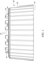
- FIG. 1 illustrates a perspective side view of a base element 100.
- the base element 100 is a part of a water collection module that constitutes a water reservoir (not shown) and the base element 100 such that the water reservoir is removably mounted on the base element 100.
- the base element 100 of the water collection module includes a bottom side 102.
- the base element 100 also includes a top side 104.
- the top side 104 is opposite to the bottom side 102.
- the top side 104 is connected to the bottom side 102 via a side surface 106.
- the base element 100 has a frustum or tapered cylinder like shape.
- the side surface 106 is a slanted surface joining the top side 104 and the bottom side 102.
- the bottom side 102 and the top side 104 both have a circular cross-section. Area of the bottom side 102 is marginally greater than an area of the top side 104.
- the top side 104 further includes a plurality of protrusions 107.
- the plurality of protrusions 107 are spread over an annular surface of the top side 104.
- Each of the plurality of protrusions 107 are separated from each other by equal or unequal distances.
- each of the plurality of protrusions 107 includes two crests separated by a trough.
- each of the plurality of protrusions 107 is defined along three perpendicular axis (not shown) such that each of the plurality of protrusions 107 has a length, a breadth, and a height.
- the trough of some of the plurality of the protrusions 107 is marginally above the surface of the top side 104 while the trough of remaining protrusions 107 aligns with the surface of the top side 104. Further, the two crests of each of the plurality of protrusions 107 is similar in height while the two crests of each of remaining protrusions 107 is different in height. Further, the maximum height of the crests of the plurality of protrusions 107 is similar. Further, some of the plurality of protrusions 107 have one crest of the two crests having height similar to the height of the corresponding trough.
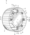
- FIG. 2 illustrates a perspective bottom view of the base element 100.
- the bottom side 102 forms a base face for standing the base element 100 on an underlying surface.
- a plurality of legs 108 extends from the top side 104 to the bottom side 102 to support the base element 100 on the underlying surface.
- a circumference of the bottom side 102 and the plurality of legs 108 take up all the weight being put upon the base element 100 in a top to down direction, i.e., in a direction leading from the top side 104 towards the bottom side 102.
- the plurality of legs 108 are not visible to a user when the base element 100 removably mounting the water reservoir is standing on the underlying surface as the plurality of legs 108 are surrounded by the side surface 106 and the water reservoir mounted on the base element 100.
- the plurality of legs 108 are at least partially hollow.
- the plurality of legs 108 have different cross-section areas.
- the plurality of legs 108 further includes a foot 109 corresponding to each of the plurality of legs 108.
- the foot 109 is formed in one piece with the corresponding leg 108.
- the foot 109 is formed at the bottom of each of the plurality of legs 108.
- the foot 109 forms a contact surface of the leg 108 with the underlying surface.
- FIG. 2 also shows a holding structure 110 of the base element 100.
- the holding structure 110 and the base element 100 are integrally formed.
- the holding structure 110 and the base element 100 are conceived as a single unit.
- the holding structure 110 is not visible from outside when the base element 100 removably mounting the water reservoir is standing on the underlying surface as the holding structure 110 is surrounded by the side surface 106 and the water reservoir mounted on the base element 100.
- the holding structure 110 at least partially extends from the top side 104 to the bottom side 102.
- FIG. 3 illustrates a perspective top view of the base element 100.
- the side opposite to the bottom side 102, i.e., the top side 104 forms a mounting face to hold any other device.
- the top side 104 includes the plurality of protrusions 107 spread at various positions over the annular surface of the top side 104. Further, each of the plurality of protrusions 107 as already discussed includes two crests separated by the trough. The crests with the equivalent maximum height across each of the plurality of protrusions 107 form an actual mounting face to hold any other device.
- the top side 104 holds any other device via the plurality of protrusions 107 integrally formed with the top side 104.
- the other device is the water reservoir such that the water reservoir is removably mounted to the top side 104 of the base element 100.
- the water collection module includes the water reservoir housed on top of the base element 100.
- the base element 100 further includes the holding structure 110 formed inside the base element 100.
- the holding structure 110 incorporates at least one holding pocket 112 for removably holding a watering accessory.
- the at least one holding pocket 112 as shown in FIG. 3 is three holding pockets 112 with different spatial volume.
- the at least one holding pocket 112 has a depth at least partially extending from the top side 104 to the bottom side 102.
- the at least one holding pocket 112 are separated from each other via walls 114.
- the walls 114 at least partially separate the one holding pocket 112 from the adjacent holding pocket 112.
- the at least one holding pocket 112 is annularly enclosed by the base element 100.
- the base element 100 as shown in FIG. 3 also includes an opening 116 to access the watering accessory removably held by the at least one holding pocket 112.
- the opening 116 is formed on the side surface 106 of the base element 100.
- the opening 116 acts as an interface between the inside of the base element 100 and the outside of the base element 100.
- the inside of the base element 100 is at least partially visible from the outside of the base element 100 via the opening 116.
- the opening 116 at least partially provides access to the holding structure 110 and the at least one holding pocket 112 and the watering accessory removably held in the base element 100.
- FIG. 4 illustrates another perspective top view of the base element 100.
- the base element 100 includes the bottom side 102 and the top side 104 connected by the side surface 106.
- the base element 100 further includes the holding structure 110 formed inside the base element 100.
- the holding structure 110 incorporates the at least one holding pocket 112 for removably holding the watering accessory.
- the at least one holding pocket 112 is separated from one another by the walls 114.
- the base element 100 further includes the plurality of legs 108 to bear the weight of the holding structure 110, the watering accessory, and the water reservoir removably mounted on the base element 100.
- the plurality of legs 108 allow the base element 100 to stand or rest on the underlying surface in a stable and secure manner.
- the base element 100 includes the opening 116 to access the watering accessory.
- the opening 116 is formed on the side surface 106 of the base element 100.
- FIG. 5 illustrates a perspective top view of the base element 100 removably holding two water accessories.
- the watering accessory is formed by one of a pump and/or a hose and/or a hose reel.
- the two watering accessories shown in FIG. 5 are the pump 118 and the hose reel 120.
- the pump 118 is removably held in one holding pocket 112 and the hose reel 120 is removably held in another adjacent holding pocket 112 separated by a wall 114 configured at least partially separating the adjacent holding pockets 112.
- the hose reel 120 as well as the pump 118 are removably held in an upright position.
- the hose reel 120 further includes a hose 122 winded on the hose reel 120.
- the hose 122 is accessible by the user via the opening 116 of the base element 100.
- the pump 118 and the hose reel 120 is at least partially enclosed by the at least one holding pocket 112. Further, the plurality of legs 108 are at least partially hollow but have sufficient strength to take upon the weight of the water reservoir, the pump 118, and the hose reel 120 such that the water collection module is held on the underlying surface in the stable and secure manner.
- the holding structure 110 incorporates the holding pocket 112 for holding a water inlet, such as a hose which may be configured to receive collected or stored water from the water reservoir, particularly a water outlet of the water reservoir.
- a water inlet such as a hose which may be configured to receive collected or stored water from the water reservoir, particularly a water outlet of the water reservoir.
- the holding structure 110 incorporates the holding pocket 112 for holding at least one tube or hose to transport water entering the base element 100 via the water inlet.
- the water inlet may be fluidly connected with the at least one tube or hose held in the holding pocket of the holding structure.
- FIG. 6 illustrates a perspective side view of the base element 100 with the opening 116.
- the opening 116 has a rectangular cross-section.
- the opening 116 allows the user to take out the hose 122 of the hose reel 120 removably held in the holding structure 110.
- the opening 116 at least partially extends from the top side 104 of the base element 100 towards the bottom side 102.
- the opening 116 at least partially extends along the annular side surface 106.
- the opening 116 includes rollers 124 to allow easy winding and unwinding movement of the hose 122 respectively in and out of the opening 116 of the base element 100.
- the base element 100 includes an inspection door 126 to allow inspection of the pump 118 and the hose reel 120 and/or any other watering accessory removably held in the base element 100.
- the circumference of the bottom side 102 of the base element 100 takes up all the weight being put upon the base element 100 in the top to down direction. In other words, there are no legs 108 extending from the top side 104 to the bottom side 102 to support the base element 100 on the underlying surface. Further, several or even all other portions of the base element 100 interior to the circumference of the bottom side 102, particularly the holding structure 110 are structurally lifted marginally relative to the circumference of the bottom side 102.
- FIG. 7 illustrates a perspective side view of the plurality of base elements 100 assembled in the stacked configuration and formed without the plurality of legs 108.
- the plurality of base elements 100 are four in number, namely a first base element 100, a second base element 100, a third base element 100, and a fourth base element 100.
- the bottom side 102 of the first base element 100 rests on the underlying surface.
- the second base element 100 is stacked on the first base element 100 such that the first base element 100 is at least partially stuck in the second base element 100.
- the top side 104 of the first base element 100 including the plurality of protrusions 107 is completely stuck in the second base element 100.
- the side surface 106 of the first base element 100 is at least partially stuck in the second base element 100.
- the top side 104 of the first base element 100 including the plurality of protrusions 107 are completely covered by the overlying second base element 100 and the side surface 106 of the first base element 100 is at least partially covered by the overlying second base element 100.
- the third base element 100 is stacked on the second base element 100 and the fourth base element 100 is stacked on the third base element 100.
Landscapes
- Engineering & Computer Science (AREA)
- Water Supply & Treatment (AREA)
- Life Sciences & Earth Sciences (AREA)
- Environmental Sciences (AREA)
- Environmental & Geological Engineering (AREA)
- Health & Medical Sciences (AREA)
- Hydrology & Water Resources (AREA)
- Public Health (AREA)
- Supports For Pipes And Cables (AREA)
Abstract
A base element (100) of a water collection module includes a bottom side (102). The base element (100) also includes a top side (104), which is opposite to the bottom side (102) and connected to the bottom side (102) via a side surface (106). The bottom side (102) forms a base face for standing the base element (100) on an underlying surface and the opposite side, i.e., the top side (104) forms a mounting face to hold any other device, in particular a water reservoir, mounted to it. The base element (100) is characterized in that a holding structure (110) is formed inside the base element (100). The holding structure (110) incorporates at least one holding pocket (112) for removably holding a watering accessory.
Description
- The present disclosure relates to a water collection module, and more particularly to a base element of a water collection module that may allow easy access of collected water.
- Many areas of the world rely upon the collection and use of reclaimed precipitation as a primary source of usable water. Water reservoirs and other devices are utilized for the purpose of collecting and storing water runoff from impervious surfaces such as the rooftops of dwellings. While generally unpotable, such systems provide a useful source of water for tasks such as irrigation, washing cars or driveways, and the like.
- Many such water reservoirs and other similar rainwater recollection systems store the water in a stagnant, manually accessed manner. Items such as pails or buckets are often the only means of accessing and transporting the water. As such, the process of utilizing the reclaimed water is often tedious or impossible, thus reducing the efficiency of employing such methods and resulting in the use of municipal wells or other sources of water for many tasks, which in turn eliminates the usefulness and purposes of such water reservoir systems.
- Further, because of continuous innovation to allow easy access of collected water, systems have been developed in which the water reservoir are mounted on a base element to elevate the water reservoir for access to the water. The water is extracted from the water reservoir by opening a spigot provided near the bottom of the water reservoir and filling a container such as a watering can. A soaker hose may also be attached to the bottom of the water reservoir to water nearby plants.
- However, such systems do not provide an adequate means for the varied reuse of the collected water according to a user's needs. Further, such systems do not provide adequate storage and pressurizing means to allow a user to use the water in a simple and conventional manner upon collection. Accordingly, there exists a need for a rainwater collection system or module for facilitating easy access to the stored water from the water reservoir for further usage in an ergonomic and efficient manner.
- An example of an improved water collection module is provided in
United States Patent US 8,578,976 B1 (hereinafter referred to as '976 reference). The '976 reference provides a water collection module with a water reservoir mounted on top of a hollow base element. At the bottom of the water reservoir there is a water outlet to which various watering components may be fixed and which may then be housed inside a free space surrounded by the base element. - In view of the above, it is an objective of the present invention to solve or at least reduce the drawbacks discussed above. The objective is at least partially achieved by a base element of a water collection module.
- According to an aspect of the present invention, the base element of the water collection module includes a bottom side. The base element also includes a top side, which is opposite to the bottom side, and connected to the bottom side via a side surface. The bottom side forms a base face for standing the base element on an underlying surface and the opposite side, i.e., the top side forms a mounting face to hold any other device, in particular a water reservoir, mounted to it. The base element is characterized in that a holding structure is formed inside the base element. The holding structure incorporates at least one holding pocket for removably holding a watering accessory.
- Thus, the present disclosure provides an improved base element for the water reservoir. The base element may provide a certain height to the water reservoir relative to the underlying surface, which may allow easy access of the water stored in the water reservoir, for example by opening a tap provided proximate to a bottom of the water reservoir. The base element advantageously includes the holding structure incorporating at least one holding pocket. The at least one holding pocket allows to removably hold at least one watering accessory, which may be configured to transport water collected or stored in the water reservoir for various applications, such as, but not limited to, gardening, kitchen uses, household purposes, etc. The at least one watering accessory, which may be removably held in the at least one holding pocket may enable an easy and ergonomic access of the collected water. The at least one watering accessory may allow to access water from the water reservoir without changing structural orientation of the water collection module such as unmounting of the water reservoir from the top surface of the base element. This may save any extra effort or manpower to be used for accessing water. Further, the at least one holding pocket may allow removable holding of the at least one watering accessory in an organized and stable manner.
- The water collection module according to the present invention may denote an assembly of the water reservoir and the base element such that the water reservoir may be mounted on the base element.
- According to an exemplary embodiment of the invention, the base element may have a tapered cylinder, or frustum like shape. However, the base element may have any other shape and size without limiting the scope of the present invention.
- According to an exemplary embodiment of the invention, the base element and the holding structure are integrally formed. The base element and the holding structure may preferably be made from a plastic material and may be integrally formed by any means known in the art. The integral formation may prove to be cost-effective, fast, and simple way of manufacturing the base element and the holding structure.
- According to an exemplary embodiment of the invention, the at least one holding pocket may be formed using a plastic material by employing any manufacturing process such as, but not limited to, molding. The at least one holding pocket may be clipped or glued to the base element or may be integrally formed with the base element.
- According to a further exemplary embodiment of the invention, the at least one holding pocket may be formed using foamed material that is connected to the base element. The foamed material may advantageously have benefits such as, but not limited to, thermal insulation, high strength per unit weight, and ease of molding. The at least one holding pocket may be able to soak in heat produced by the watering accessory held by the at least one holding pocket such that other watering accessories arranged nearby may continue their operation without any affect or influence of heat. The at least one holding pocket may for example be made from one or more of vinyls, polystyrene, polyethylene, phenolics, silicones, cellulose acetate, and urethanes.
- According to an exemplary embodiment of the invention, the at least one holding pocket may include at least one coupling cavity to allow fluid coupling between the various watering accessories removably held in the at least one holding pocket such that the watering accessories may be required to be fluidly coupled for allowing transport of the collected water for various applications.
- According to an exemplary embodiment of the invention, the watering accessory is formed by one of a pump and/or a hose and/or a hose reel. One or more watering accessories may be removably held or stored in the at least one holding pocket of the holding structure integrally formed with the base element. However, all the water accessories may or may not be required to be in operation simultaneously. The water accessories to be held or stored in the base element may be selected by a user based on current and future application requirements. For example, the user may store the pump in the base element, and a few years after may realize a need for the hose reel to be used in conjunction with the pump and then may store the hose reel as well in the base element and fluidly connect both the pump and the hose reel. The watering accessories such as the pump, the hose, and the hose reel may alone or together allow the user to have easy access of the water stored in the water reservoir for various industrial and domestic applications. Further, the watering accessory may be any water accessory other than the pump, the hose, and the hose reel as well.
- According to an exemplary embodiment of the invention, the holding structure incorporates the holding pocket for holding a water inlet. The water inlet is configured to receive water from the water reservoir. The water inlet may be fluidly connected or coupled to a water outlet of the water reservoir which may be provided at the bottom of the water reservoir. The water inlet may be a hose, which may be fluidly coupled to the water outlet of the water reservoir using, for example, a hose connector. The water inlet may be advantageously held in the holding pocket and may act as an interface between the water outlet of the water reservoir and the other watering accessories such as the pump, the hose, or the hose reel held in the holding structure of the based element.
- According to an exemplary embodiment of the invention, the holding structure incorporates the holding pocket for holding at least one tube or hose to transport water entering the base element via the water inlet. The water inlet may be fluidly connected with the at least one tube or hose held in the holding pocket of the holding structure. The at least one tube or hose may further be fluidly connected with the watering accessory, for example, the pump, or the hose reel held in an adjacent holding pocket such that the water received from the water inlet may be transferred to the watering accessory for to allow for easy access of the collected or stored water for the user.
- According to an exemplary embodiment of the invention, the base element includes an opening to access the watering accessory. The opening may be one or more openings formed on the side surface of the base element. The opening may allow, for example, a hose of the hose reel to be taken out and fluidly connect with a garden spray, and the like.
- According to an exemplary embodiment of the invention, the opening in the side surface of the base element may be formed by removing a separable part from the base element after purchase of the base element. However, the opening may be covered after use with a hinged door like structure without affecting the aesthetics of the base element.
- According to an exemplary embodiment of the invention, the opening in the side surface of the base element may be formed by sliding out a separable part that may slidingly be removed from the side surface of the base element when the access to the watering accessory is required and that may be slidingly be engaged back with side surface when the access to the watering accessory is not required. This may retain the aesthetics of the base element.
- According to an exemplary embodiment of the invention, the hose reel is held in an upright position. The hose reel is removably held in the upright position in the holding pocket such that the hose of the hose reel may conveniently be taken out of the opening of the base element and may conveniently be winded back in the hose reel without any tangling, or other similar problems. However, the hose reel may be held in any other suitable position as well. For example, the hose reel may be held in a vertical position. In an advantageous embodiment the base element or the hose reel itself embodies a hose guide that aids the coiling of the hose onto the hose reel avoiding an entanglement of the hose during the winding process.
- According to an exemplary embodiment of the invention, a plurality of legs extends from the top side to the bottom side to support the base element on the underlying surface. The plurality of legs may be any number of legs. The plurality of legs along with a circumference of the bottom side may take up the forces due to the weight of the water reservoir, one or watering accessories, and the fluid connection arrangements inside of the base element such that the base element with all the removably held components discussed above may be stably held on the underlying surface and the collected water may be easily and ergonomically accessed by the user.
- According to an exemplary embodiment of the invention, the plurality of legs may be equidistant. The equidistant legs may be able to divide the force or weight of the water reservoir, one or watering accessories, and the fluid connection arrangements inside of the base element equally among themselves. Further, the plurality of legs may have a solid or hollow body.
- According to an exemplary embodiment of the invention, the circumference of the bottom side may take up all the weight of the water reservoir, one or watering accessories, and the fluid connection arrangements inside of the base element such that the base element with all the removably held components discussed above may be stably held on the underlying surface and the collected water may be easily and ergonomically accessed by the user. Further, all other portions of the base element interior to the circumference of the bottom side, particularly the holding structure may be structurally lifted marginally relative to the circumference of the bottom side. Such a design of the base element may be particularly beneficial for compact storage and transportation of a plurality of base elements such as by stacking of the plurality of base elements.
- According to a further aspect of the present invention, the water collection module includes the water reservoir housed on top of the base element. The water reservoir may be a water tank, and the like that may be stably held, housed, or mounted on top of the base element. The water reservoir may further be covered with a cover to prevent contamination of the collected water.
- Before discussing the invention with the help of the drawings the invention will be briefly discussed in general. A base element is designed to be placed below a water reservoir. The base element includes prefabricated structures which may enable a user to implement suitable accessories inside the base element easily. This compact and integrated solution may connect a hose or hose box, a pump, a battery compartment, a pipeline system, and a watering automation equipment (or a watering computer). The base element may be used just to increase the height of the water reservoir when there is no accessory implemented inside the base element.
- The base element according to the present invention may provide one solution for all necessary steps required to be taken to use rainwater. The base element according to the present invention may provide modularity and combination of different accessories according to consumer needs. The base element according to the present invention may provide high grade of mechanical linkage to handle forces caused by usage of the accessories. Further, the base element according to the present invention may provide elevated water reservoir, which may facilitate filling of a water can, and the like. Further, the base element according to the present invention may improve efficiency of the rainwater usage by reducing distances between the water reservoir and the hose or pipeline system. Further, the base element according to the present invention may provide a puristic design such that there may be only one element in the garden leading to a tidy garden. Further, the base element according to the present invention may provide a closed, clean system such that no insects, no leaves, no algae, or other polluting elements may affect collected water. Further, the base element according to the present invention may functionally provide a stable stand to the water reservoir.
- According to an exemplary embodiment of the invention, the base element may be placed below or next to the water reservoir and may include preproduced structures to be connected with the suitable accessory like the pump, battery compartment, garden hose, automatic garden hose box or equipment for automatic irrigation.
- Other features and aspects of this invention will be apparent from the following description and the accompanying drawings.
- The invention will be described in more detail with reference to the enclosed drawings, wherein:
-
FIG. 1 illustrates a perspective side view of a base element, in accordance with an exemplary embodiment of the present disclosure; -
FIG. 2 illustrates a perspective bottom view of a base element, in accordance with an exemplary embodiment of the present disclosure; -
FIG. 3 illustrates a perspective top view of a base element, in accordance with an exemplary embodiment of the present disclosure; -
FIG. 4 illustrates another perspective top view of a base element, in accordance with an exemplary embodiment of the present disclosure; -
FIG. 5 illustrates a perspective top view of a base element removably holding two water accessories, in accordance with an exemplary embodiment of the present disclosure; -
FIG. 6 illustrates a perspective side view of a base element with an opening, in accordance with an exemplary embodiment of the present disclosure; and -
FIG. 7 illustrates a perspective side view of a plurality of base elements assembled in a stacked configuration, in accordance with an exemplary embodiment of the present disclosure. - The present invention will be described more fully hereinafter with reference to the accompanying drawings, in which example embodiments of the invention incorporating one or more aspects of the present invention are shown. This invention may, however, be embodied in many different forms and should not be construed as limited to the embodiments set forth herein; rather, these embodiments are provided so that this disclosure will be thorough and complete, and will fully convey the scope of the invention to those skilled in the art. For example, one or more aspects of the present invention may be utilized in other embodiments and even other types of structures and/or methods. In the drawings, like numbers refer to like elements.
- Certain terminology is used herein for convenience only and is not to be taken as a limitation on the invention. For example, "upper", "lower", "front", "rear", "side", "longitudinal", "lateral", "transverse", "upwards", "downwards", "forward", "backward", "sideward", "left," "right," "horizontal," "vertical," "upward", "inner", "outer", "inward", "outward", "top", "bottom", "higher", "above", "below", "central", "middle", "intermediate", "between", "end", "adjacent", "proximate", "near", "distal", "remote", "radial", "circumferential", or the like, merely describe the configuration shown in the Figures. Indeed, the components may be oriented in any direction and the terminology, therefore, should be understood as encompassing such variations unless specified otherwise.
-
FIG. 1 illustrates a perspective side view of abase element 100. Thebase element 100 is a part of a water collection module that constitutes a water reservoir (not shown) and thebase element 100 such that the water reservoir is removably mounted on thebase element 100. Thebase element 100 of the water collection module includes abottom side 102. Thebase element 100 also includes atop side 104. Thetop side 104 is opposite to thebottom side 102. Thetop side 104 is connected to thebottom side 102 via aside surface 106. Thebase element 100 has a frustum or tapered cylinder like shape. Theside surface 106 is a slanted surface joining thetop side 104 and thebottom side 102. Thebottom side 102 and thetop side 104 both have a circular cross-section. Area of thebottom side 102 is marginally greater than an area of thetop side 104. - The
top side 104 further includes a plurality ofprotrusions 107. The plurality ofprotrusions 107 are spread over an annular surface of thetop side 104. Each of the plurality ofprotrusions 107 are separated from each other by equal or unequal distances. Further, each of the plurality ofprotrusions 107 includes two crests separated by a trough. Further, each of the plurality ofprotrusions 107 is defined along three perpendicular axis (not shown) such that each of the plurality ofprotrusions 107 has a length, a breadth, and a height. The trough of some of the plurality of theprotrusions 107 is marginally above the surface of thetop side 104 while the trough of remainingprotrusions 107 aligns with the surface of thetop side 104. Further, the two crests of each of the plurality ofprotrusions 107 is similar in height while the two crests of each of remainingprotrusions 107 is different in height. Further, the maximum height of the crests of the plurality ofprotrusions 107 is similar. Further, some of the plurality ofprotrusions 107 have one crest of the two crests having height similar to the height of the corresponding trough. -
FIG. 2 illustrates a perspective bottom view of thebase element 100. Thebottom side 102 forms a base face for standing thebase element 100 on an underlying surface. Further, a plurality oflegs 108 extends from thetop side 104 to thebottom side 102 to support thebase element 100 on the underlying surface. A circumference of thebottom side 102 and the plurality oflegs 108 take up all the weight being put upon thebase element 100 in a top to down direction, i.e., in a direction leading from thetop side 104 towards thebottom side 102. The plurality oflegs 108 are not visible to a user when thebase element 100 removably mounting the water reservoir is standing on the underlying surface as the plurality oflegs 108 are surrounded by theside surface 106 and the water reservoir mounted on thebase element 100. The plurality oflegs 108 are at least partially hollow. The plurality oflegs 108 have different cross-section areas. The plurality oflegs 108 further includes afoot 109 corresponding to each of the plurality oflegs 108. Thefoot 109 is formed in one piece with thecorresponding leg 108. Thefoot 109 is formed at the bottom of each of the plurality oflegs 108. Thefoot 109 forms a contact surface of theleg 108 with the underlying surface. -
FIG. 2 also shows a holdingstructure 110 of thebase element 100. The holdingstructure 110 and thebase element 100 are integrally formed. The holdingstructure 110 and thebase element 100 are conceived as a single unit. The holdingstructure 110 is not visible from outside when thebase element 100 removably mounting the water reservoir is standing on the underlying surface as the holdingstructure 110 is surrounded by theside surface 106 and the water reservoir mounted on thebase element 100. The holdingstructure 110 at least partially extends from thetop side 104 to thebottom side 102. -
FIG. 3 illustrates a perspective top view of thebase element 100. The side opposite to thebottom side 102, i.e., thetop side 104 forms a mounting face to hold any other device. Thetop side 104 includes the plurality ofprotrusions 107 spread at various positions over the annular surface of thetop side 104. Further, each of the plurality ofprotrusions 107 as already discussed includes two crests separated by the trough. The crests with the equivalent maximum height across each of the plurality ofprotrusions 107 form an actual mounting face to hold any other device. In other words, thetop side 104 holds any other device via the plurality ofprotrusions 107 integrally formed with thetop side 104. The other device is the water reservoir such that the water reservoir is removably mounted to thetop side 104 of thebase element 100. In other words, the water collection module includes the water reservoir housed on top of thebase element 100. - The
base element 100 further includes the holdingstructure 110 formed inside thebase element 100. The holdingstructure 110 incorporates at least one holdingpocket 112 for removably holding a watering accessory. The at least one holdingpocket 112 as shown inFIG. 3 is three holdingpockets 112 with different spatial volume. The at least one holdingpocket 112 has a depth at least partially extending from thetop side 104 to thebottom side 102. The at least one holdingpocket 112 are separated from each other viawalls 114. Thewalls 114 at least partially separate theone holding pocket 112 from the adjacent holdingpocket 112. The at least one holdingpocket 112 is annularly enclosed by thebase element 100. - Further, the
base element 100, as shown inFIG. 3 also includes anopening 116 to access the watering accessory removably held by the at least one holdingpocket 112. Theopening 116 is formed on theside surface 106 of thebase element 100. The opening 116 acts as an interface between the inside of thebase element 100 and the outside of thebase element 100. The inside of thebase element 100 is at least partially visible from the outside of thebase element 100 via theopening 116. Theopening 116 at least partially provides access to the holdingstructure 110 and the at least one holdingpocket 112 and the watering accessory removably held in thebase element 100. -
FIG. 4 illustrates another perspective top view of thebase element 100. Thebase element 100 includes thebottom side 102 and thetop side 104 connected by theside surface 106. Thebase element 100 further includes the holdingstructure 110 formed inside thebase element 100. The holdingstructure 110 incorporates the at least one holdingpocket 112 for removably holding the watering accessory. The at least one holdingpocket 112 is separated from one another by thewalls 114. Thebase element 100 further includes the plurality oflegs 108 to bear the weight of the holdingstructure 110, the watering accessory, and the water reservoir removably mounted on thebase element 100. The plurality oflegs 108 allow thebase element 100 to stand or rest on the underlying surface in a stable and secure manner. Further, thebase element 100 includes theopening 116 to access the watering accessory. Theopening 116 is formed on theside surface 106 of thebase element 100. -
FIG. 5 illustrates a perspective top view of thebase element 100 removably holding two water accessories. The watering accessory is formed by one of a pump and/or a hose and/or a hose reel. However, the two watering accessories shown inFIG. 5 are thepump 118 and thehose reel 120. Thepump 118 is removably held in one holdingpocket 112 and thehose reel 120 is removably held in another adjacent holdingpocket 112 separated by awall 114 configured at least partially separating the adjacent holding pockets 112. Thehose reel 120 as well as thepump 118 are removably held in an upright position. Thehose reel 120 further includes ahose 122 winded on thehose reel 120. Thehose 122 is accessible by the user via theopening 116 of thebase element 100. - Further, the
pump 118 and thehose reel 120 is at least partially enclosed by the at least one holdingpocket 112. Further, the plurality oflegs 108 are at least partially hollow but have sufficient strength to take upon the weight of the water reservoir, thepump 118, and thehose reel 120 such that the water collection module is held on the underlying surface in the stable and secure manner. - Further, in another embodiment, the holding
structure 110 incorporates the holdingpocket 112 for holding a water inlet, such as a hose which may be configured to receive collected or stored water from the water reservoir, particularly a water outlet of the water reservoir. - Further, in yet another embodiment, the holding
structure 110 incorporates the holdingpocket 112 for holding at least one tube or hose to transport water entering thebase element 100 via the water inlet. The water inlet may be fluidly connected with the at least one tube or hose held in the holding pocket of the holding structure. -
FIG. 6 illustrates a perspective side view of thebase element 100 with theopening 116. Theopening 116 has a rectangular cross-section. Theopening 116 allows the user to take out thehose 122 of thehose reel 120 removably held in the holdingstructure 110. Theopening 116 at least partially extends from thetop side 104 of thebase element 100 towards thebottom side 102. Theopening 116 at least partially extends along theannular side surface 106. Further, theopening 116 includesrollers 124 to allow easy winding and unwinding movement of thehose 122 respectively in and out of theopening 116 of thebase element 100. Further, thebase element 100 includes aninspection door 126 to allow inspection of thepump 118 and thehose reel 120 and/or any other watering accessory removably held in thebase element 100. - In another embodiment of the present invention, the circumference of the
bottom side 102 of thebase element 100 takes up all the weight being put upon thebase element 100 in the top to down direction. In other words, there are nolegs 108 extending from thetop side 104 to thebottom side 102 to support thebase element 100 on the underlying surface. Further, several or even all other portions of thebase element 100 interior to the circumference of thebottom side 102, particularly the holdingstructure 110 are structurally lifted marginally relative to the circumference of thebottom side 102. -
FIG. 7 illustrates a perspective side view of the plurality ofbase elements 100 assembled in the stacked configuration and formed without the plurality oflegs 108. For illustration purposes, the plurality ofbase elements 100 are four in number, namely afirst base element 100, asecond base element 100, athird base element 100, and afourth base element 100. - In the stacked configuration, the
bottom side 102 of thefirst base element 100 rests on the underlying surface. Further, thesecond base element 100 is stacked on thefirst base element 100 such that thefirst base element 100 is at least partially stuck in thesecond base element 100. In other words, when thesecond base element 100 is stacked on thefirst base element 100, thetop side 104 of thefirst base element 100 including the plurality ofprotrusions 107 is completely stuck in thesecond base element 100. Further, theside surface 106 of thefirst base element 100 is at least partially stuck in thesecond base element 100. In other words, when thefirst base element 100 and thesecond base element 100 are stacked together, then thetop side 104 of thefirst base element 100 including the plurality ofprotrusions 107 are completely covered by the overlyingsecond base element 100 and theside surface 106 of thefirst base element 100 is at least partially covered by the overlyingsecond base element 100. Likewise, thethird base element 100 is stacked on thesecond base element 100 and thefourth base element 100 is stacked on thethird base element 100. - In the drawings and specification, there have been disclosed exemplary embodiments and examples of the invention and, although specific terms are employed, they are used in a generic and descriptive sense only and not for the purpose of limitation of the scope of the invention being set forth in the following claims.
-
- 100
- Base Element
- 102
- Bottom Side
- 104
- Top Side
- 106
- Side Surface
- 107
- Protrusions
- 108
- Legs
- 109
- Foot
- 110
- Holding Structure
- 112
- Holding Pocket
- 114
- Walls
- 116
- Opening
- 118
- Pump
- 120
- Hose Reel
- 122
- Hose
- 124
- Rollers
- 126
- Inspection Door
Claims (9)
- A base element (100) of a water collection module, comprising:a bottom side (102) and opposite to it and connected via a side surface (106) a top side (104);wherein the bottom side (102) forms a base face for standing the base element (100) on an underlying surface; andwherein the top side (104) forms a mounting face to hold any other device, in particular a water reservoir, mounted to it;characterized in that:a holding structure (110) is formed inside the base element (100); andthe holding structure (110) incorporates at least one holding pocket (112) for removably holding a watering accessory.
- The base element (100) according to claim 1, wherein the base element (100) and the holding structure (110) are integrally formed.
- The base element (100) according to any one of the preceding claims, wherein the watering accessory is formed by one of a pump (118) and/or a hose and/or a hose reel (120).
- The base element (100) according to one of the claims 1 to 2, wherein the holding structure (110) incorporates the holding pocket (112) for holding a water inlet, wherein the water inlet is configured to receive water from the water reservoir.
- The base element (100) according to claim 4, wherein the holding structure (110) incorporates the holding pocket (112) for holding at least one tube or hose to transport water entering the base element (100) via the water inlet.
- The base element (100) according to claim 1, wherein the base element (100) includes an opening (116) to access the watering accessory.
- The base element (100) according to claim 3, wherein the hose reel (120) is held in an upright position.
- The base element (100) according to claim 1, wherein a plurality of legs (108) extends from the top side (104) to the bottom side (102) to support the base element (100) on the underlying surface.
- The water collection module, comprising of the water reservoir housed on top of the base element (100) according to one of the claims 1-8.
Priority Applications (1)
| Application Number | Priority Date | Filing Date | Title |
|---|---|---|---|
| EP23174924.3A EP4467732A1 (en) | 2023-05-23 | 2023-05-23 | Water collection module |
Applications Claiming Priority (1)
| Application Number | Priority Date | Filing Date | Title |
|---|---|---|---|
| EP23174924.3A EP4467732A1 (en) | 2023-05-23 | 2023-05-23 | Water collection module |
Publications (1)
| Publication Number | Publication Date |
|---|---|
| EP4467732A1 true EP4467732A1 (en) | 2024-11-27 |
Family
ID=86497796
Family Applications (1)
| Application Number | Title | Priority Date | Filing Date |
|---|---|---|---|
| EP23174924.3A Pending EP4467732A1 (en) | 2023-05-23 | 2023-05-23 | Water collection module |
Country Status (1)
| Country | Link |
|---|---|
| EP (1) | EP4467732A1 (en) |
Citations (7)
| Publication number | Priority date | Publication date | Assignee | Title |
|---|---|---|---|---|
| EP0633363A1 (en) * | 1993-07-08 | 1995-01-11 | WILO GmbH | Container for the collection of rainwater |
| WO1995025852A1 (en) * | 1994-03-18 | 1995-09-28 | Zapf Gmbh + Co. | Prefabricated stucture of ferroconcrete or a substitute material |
| US7025879B1 (en) * | 2004-03-12 | 2006-04-11 | Ticknor Martin F | Rainwater collection apparatus and pumping system |
| KR20080112531A (en) * | 2007-06-21 | 2008-12-26 | 재단법인서울대학교산학협력재단 | Rainwater storage tank |
| US8578976B1 (en) | 2008-12-15 | 2013-11-12 | Stephen D. Davis | Rain water collection system |
| GB2527163A (en) * | 2015-01-07 | 2015-12-16 | David Edmondson | An apparatus for storage and dispensing of a liquid |
| WO2016151560A2 (en) * | 2015-03-25 | 2016-09-29 | Cronin, Gerard | A rainwater collection container |
-
2023
- 2023-05-23 EP EP23174924.3A patent/EP4467732A1/en active Pending
Patent Citations (7)
| Publication number | Priority date | Publication date | Assignee | Title |
|---|---|---|---|---|
| EP0633363A1 (en) * | 1993-07-08 | 1995-01-11 | WILO GmbH | Container for the collection of rainwater |
| WO1995025852A1 (en) * | 1994-03-18 | 1995-09-28 | Zapf Gmbh + Co. | Prefabricated stucture of ferroconcrete or a substitute material |
| US7025879B1 (en) * | 2004-03-12 | 2006-04-11 | Ticknor Martin F | Rainwater collection apparatus and pumping system |
| KR20080112531A (en) * | 2007-06-21 | 2008-12-26 | 재단법인서울대학교산학협력재단 | Rainwater storage tank |
| US8578976B1 (en) | 2008-12-15 | 2013-11-12 | Stephen D. Davis | Rain water collection system |
| GB2527163A (en) * | 2015-01-07 | 2015-12-16 | David Edmondson | An apparatus for storage and dispensing of a liquid |
| WO2016151560A2 (en) * | 2015-03-25 | 2016-09-29 | Cronin, Gerard | A rainwater collection container |
Similar Documents
| Publication | Publication Date | Title |
|---|---|---|
| CA1204367A (en) | Parts cleaner adapted for simplified use | |
| US20060157946A1 (en) | Receptacle caddy | |
| US8807493B2 (en) | Wheeled bucket stand | |
| US11815284B2 (en) | Dehumidifier with condensate tank | |
| CA3049209A1 (en) | Pipe support | |
| US6938299B2 (en) | Wet-dry vacuum cleaner with securely nestable tool holder and basket | |
| US20130186306A1 (en) | Portable Utility Table | |
| US8573138B2 (en) | Portable table | |
| US5718178A (en) | Storage table and planter combination | |
| US8839814B2 (en) | Wall mountable hose reel | |
| US20090008280A1 (en) | Tool organizer insert | |
| US20060078987A1 (en) | Compost Container | |
| US20140084773A1 (en) | Spray Bottle Rack | |
| US9167942B1 (en) | Vacuum cleaner with hose fence and tool storage | |
| US20050257417A1 (en) | Fishing rod holder | |
| EP4467731A1 (en) | Water collection module | |
| US20070164173A1 (en) | Collapsible garbage bag supporter | |
| JP7640215B2 (en) | Portable Tank | |
| KR200496094Y1 (en) | Foldable irrigation water tank | |
| KR101991904B1 (en) | assembly a Cleaning outfit Storage | |
| CN211378968U (en) | Detachable flowerpot bracket | |
| CN210493646U (en) | Water storage jade vertical goblet for umbrella | |
| US20130087651A1 (en) | Garden hose holder with removable center post | |
| EP1685055A1 (en) | Ornamental garden hose storage device | |
| US20070018026A1 (en) | Enclosure system for supporting a sink and hose reel assembly |
Legal Events
| Date | Code | Title | Description |
|---|---|---|---|
| PUAI | Public reference made under article 153(3) epc to a published international application that has entered the european phase |
Free format text: ORIGINAL CODE: 0009012 |
|
| STAA | Information on the status of an ep patent application or granted ep patent |
Free format text: STATUS: REQUEST FOR EXAMINATION WAS MADE |
|
| 17P | Request for examination filed |
Effective date: 20231214 |
|
| AK | Designated contracting states |
Kind code of ref document: A1 Designated state(s): AL AT BE BG CH CY CZ DE DK EE ES FI FR GB GR HR HU IE IS IT LI LT LU LV MC ME MK MT NL NO PL PT RO RS SE SI SK SM TR |