EP4467730A1 - A cover for a water reservoir - Google Patents
A cover for a water reservoir Download PDFInfo
- Publication number
- EP4467730A1 EP4467730A1 EP23174926.8A EP23174926A EP4467730A1 EP 4467730 A1 EP4467730 A1 EP 4467730A1 EP 23174926 A EP23174926 A EP 23174926A EP 4467730 A1 EP4467730 A1 EP 4467730A1
- Authority
- EP
- European Patent Office
- Prior art keywords
- cover
- area
- water reservoir
- inner area
- opening
- Prior art date
- Legal status (The legal status is an assumption and is not a legal conclusion. Google has not performed a legal analysis and makes no representation as to the accuracy of the status listed.)
- Pending
Links
Images




Classifications
-
- E—FIXED CONSTRUCTIONS
- E03—WATER SUPPLY; SEWERAGE
- E03B—INSTALLATIONS OR METHODS FOR OBTAINING, COLLECTING, OR DISTRIBUTING WATER
- E03B3/00—Methods or installations for obtaining or collecting drinking water or tap water
- E03B3/02—Methods or installations for obtaining or collecting drinking water or tap water from rain-water
-
- E—FIXED CONSTRUCTIONS
- E03—WATER SUPPLY; SEWERAGE
- E03B—INSTALLATIONS OR METHODS FOR OBTAINING, COLLECTING, OR DISTRIBUTING WATER
- E03B3/00—Methods or installations for obtaining or collecting drinking water or tap water
- E03B3/02—Methods or installations for obtaining or collecting drinking water or tap water from rain-water
- E03B3/03—Special vessels for collecting or storing rain-water for use in the household, e.g. water-butts
Definitions
- the present disclosure relates to a cover for a water reservoir that may prevent contamination of water, particularly rainwater stored inside the water reservoir from debris, or other unwanted elements present in a surrounding environment.
- a water reservoir may be used to collect and store rainwater runoff, typically from rooftops via downpipes.
- the water reservoir may be installed to make use of rainwater for further applications, such as, watering gardens, agriculture, flushing toilets, in washing machines, washing cars, and for drinking, especially when other water supplies are unavailable, expensive, or of poor quality, and when adequate care is taken that the water is not contaminated and is adequately filtered.
- the water reservoir may be covered by a cover to prevent contamination of rainwater stored inside the water reservoir from debris, or other unwanted elements present in a surrounding environment.
- the water reservoir may be filled with rainwater in two well-known ways.
- a flap in the downpipe may be used to fill the water reservoir.
- the cover of the water reservoir may be required to be taken off and thus, debris, or other unwanted elements may enter the water reservoir and contaminate the stored rainwater.
- a fixed inverter may be installed to permanently connect the punctured downpipe with an upper mantle surface of the water reservoir via a hose or pipe connection. In this way, the cover may always stay on top of the water reservoir and substantially prevent the rainwater stored inside the water reservoir from contamination.
- the cover may have a convex dome shape so that dirt and unwanted rainwater may flow off. The dome shape may also allow more physical stability for the cover surface.
- '661 reference provides a rain gauge barrel that is associated with several movable aprons.
- the surface of each of the aprons is divided into two parts that are angularly arranged to each other.
- One part of the apron is a dust cover part, and the other part is a funnel part.
- the aprons are moved between two positions with the help of telescopic links mounted between each of the aprons and an outer surface of the rain gauge barrel.
- first position the telescopic links are telescoped in and the dust-cover parts of all the aprons are adjacent to each other and cover the rain gauge barrel.
- the funnel parts of the aprons are close by the outer walls of the rain gauge barrel.
- second position the telescopic links are telescoped out and thereby make the dust cover parts to move into the rain gauge barrel, while the funnel parts move above the rain gauge barrel adjacent to each other to form a funnel that funnels the rain and directs it into the rain gauge barrel.
- the rain gauge barrel is fully covered while in the second position the rainwater is directed via the aprons into the rain gauge barrel.
- the objective is at least partially achieved by the cover of a water reservoir.
- the cover of the water reservoir has an area of cover.
- the area of the cover includes an outer area at a circumference of the cover and an inner area inside the outer area.
- the inner area is not in contact with the outer area and a crossing area is disposed in-between the inner area and the outer area.
- the cover of the water reservoir is characterized in that the inner area is flexible and is configured to be moved to exhibit at least two different shapes. Further, the inner area includes an opening allowing water to pass through the cover.
- the present disclosure provides an improved design of the cover for the water reservoir.
- the cover may advantageously allow filling of the water reservoir with rainwater without having to take off the cover from the water reservoir.
- the cover may prevent contamination of the stored or collected rainwater in the water reservoir.
- the cover may be suitable for installation with a fixed inverter to allow filling of the water reservoir with rainwater.
- the cover may also be suitable to allow filling of the water reservoir with rainwater using a flap in a downpipe.
- the flexibility of the inner area of the cover may allow the inner area of the cover to assume multiple shapes relative to the outer area of the cover such that the cover may be versatile enough to allow filling of the water reservoir with rainwater in any of the traditionally known way.
- the flexibility of the inner area of the cover may further allow the inner area of the cover to assume the shape of a funnel to collect the rainwater or assume the shape of a dome that may provide slope to let go off any debris, or dirt on a surface of the cover.
- the cover may be simple and ergonomic in use and may be deformed to various required shapes simply by force of hands of a user.
- the opening in the cover may allow installation of various apparatuses, such as the fixed inverter, or a filer assembly to further facilitate easy and substantially contaminant free filling of the rainwater in the water reservoir.
- the cover may be simple in construction and easy to manufacture.
- the cover of the water reservoir has an area of cover according to the present invention.
- This may denote that the area of the cover is a body of the cover that is divided into three parts, namely the outer area, the crossing area, and the inner area such that that the inner area is inside the outer area. Further, the crossing area is a bridge portion between the outer area and the inner area to bridge the gap between the outer area and the inner area.
- the outer area, the crossing area, and the inner area may be integrally formed with any method well-suited in the art using different or similar materials without departing from the scope of the present invention.
- the outer area, the crossing area, and the inner area may be separately formed, and then bonded using known techniques such as, but not limited to, gluing, etc., to form one single cover.
- the different parts or areas of the cover may not be intended for separation once the cover may be operational.
- the outer area may be specially shaped such as to provide a comfortable gripping surface to the user.
- the surface may have a series of crests and troughs.
- the outer area may be able to dispose of or run off any debris, or dirt on its surface via force of gravity.
- the outer area may be shaped corresponding to the shape of the water reservoir for aesthetic appeal and uniformity.
- the outer area may be provided with an outlet opening, such that the stored or collected rainwater may be pumped off form the outlet opening using a hose, or the like for further applications, such as, but not limited to, gardening, car-washing, and firefighting.
- the opening allowing passage of water may be formed at the center of the cover, or the center of the inner area.
- the opening allowing passage of water may also be formed offset to the center of the inner area.
- the opening allowing passage of water may be pre-formed with the cover in a factory during manufacturing with an additional option to form or carve out more openings as per the user requirement after the purchase of the cover.
- the opening allowing passage of water may conventionally have circular cross-section or shape but may have any other shape and size without limiting the scope of the present invention.
- the opening is provided with a movable guard.
- the movable guard may be configured to be movable in a vertical direction, i.e., near or far to the ground surface when installed on the cover of the water reservoir. Further, the movable guard may be configured to guard the stored or collected rainwater against contaminants or impurities in the surroundings of the water reservoir.
- the movable guard may completely align with the opening in the inner area when the water reservoir is not being filled with rainwater. Further, the movable guard may be substantially moved in vertical direction relative to the inner area when the water reservoir is required to be filled with rainwater. Further, the shape of the movable guard may correspond to the shape of the opening in the inner area.
- the movement of the movable guard may take place due to a push or pull force of the hands of the user.
- the movement of the movable guard may take place due to rotational force imparted to the movable guard such that the movable guard is rotated like a screw to move towards or away from the ground surface in the vertical direction.
- the movable guard is removable from the cover.
- the movable guard may be removable from the cover to allow installation of inlet hoses, or pipes with the opening in the inner area such that the inlet hoses, or pipes may permanently connect the downpipe with the water reservoir.
- the movable guard may be removable to allow occasional inspection of the contents of the water reservoir.
- the movable guard may be removable to allow easy servicing of the movable guard in case of damage, and the like.
- the movable guard includes a filter filtering the water that passes through the cover.
- the movable guard may advantageously house the filter to filter out the contaminants from the incoming rainwater when the water reservoir is being filled.
- the filter may be a surface filter made of closely woven fabric or treated paper with a uniform pore size.
- the filter may be a depth filter made of layers of fabric or fibers, which provide many tortuous paths for the water to flow through.
- the filter may be of the 5-micron, woven mesh, micronic, porous metal, or magnetic type.
- the inner area is configured to be moved to exhibit a concave shape and a convex shape in respect to the outer area of the circumference of the cover.
- the inner area may be moved to the convex or dome shape when the fixed inverter may be utilized to aid filling of rainwater in the water reservoir.
- the inner area may be moved to the concave or basin like shape when the flap in the downpipe may be utilized to aid filling of rainwater in the water reservoir.
- the movement of the inner area from the convex shape to the concave shape may be configured to be tool-less.
- the movement of the inner area from the convex shape to the concave shape may be executed by force of hands of the user.
- the inner area is formed of a polypropylene material.
- the inner area may be formed from polypropylene or any other similar material, which may be flexible enough to be deformed from one shape to the other and may advantageously regain the original shape on its own in absence of any external force.
- a thickness of the crossing area is less than a thickness of the inner area and a thickness of the outer area.
- the shape of the cover thus formed along with the flexible material of the inner area may allow the inner area to assume at least two different shapes.
- the thickness of the inner area is substantially equal to the thickness of the outer area.
- the thickness of the inner area may be different than the thickness of the outer area.
- the thickness of the inner area may be less than the thickness of the outer area.
- the water reservoir includes the cover.
- the cover is mounted on top of the water reservoir.
- the water reservoir may be any kind of fixed or portable installation that may be configured to store rainwater for further domestic and industrial applications.
- the water reservoir may be a cylindrical water tank commonly used in a household.
- the water reservoir of the present invention may be equally relevant or useful for collecting and storing any other fluid, particularly liquid fluid.
- a cover is designed to be suitable for both types of installation, i.e., a classical flap in a downpipe and an installation of a fixed inverter, which may permanently connect a punctured downpipe with an upper mantle surface of the water reservoir via a hose or pipe connection. In both cases, the cover may always stay closed on the water reservoir so that impurification of the collected rainwater is permanently avoided.
- the cover may initially be domed with a convex shape. In this condition, the cover may be suitable for the installation with the fixed inverter. Further, the cover may typically be made of polypropylene or similar material, which has very flexible material characteristics.
- the cover may be simply plopped from a convex to a concave shape by a simple push onto the surface with both hands. Further, there may be no constructive elements needed but just the material in combination with the shape that may allow for this plopping function. Further, the cover may be shaped just like a basin when in concave shape. Furthermore, a circular opening may be provided in the center of the cover that may allow for the rainwater to enter the water reservoir. This circular opening may further include a movable guard which may be pulled to open or pushed to close. Optionally, a filter may be integrated into the movable guard in order to prevent impurification of the collected rainwater.
- the cover according to the present invention may be suitable for two different applications, or installations as described above.
- the cover according to the present invention may allow clean and mosquito free rainwater collection for both applications or installations.
- the cover according to the present invention may be extremely simple and intuitive modification of the already known covers in the related field without any constructive elements.
- the cover according to the present invention may be only one single piece of cover.
- the plopping principle of the cover may allow a switch from the convex to the concave cover shape with surpassing simplicity and intuition.
- FIG. 1 illustrates a schematic view of a cover 100 for covering a water reservoir according to an exemplary embodiment of the present invention.
- the water reservoir includes the cover 100 for mounting on top of the water reservoir.
- the cover 100 of the water reservoir has an area “A” of the cover 100.
- the area “A” of cover 100 includes an outer area “ A1 " and an inner area “A2".
- the outer area “ A1 " is at a circumference of the cover 100.
- the outer area “ A1 " has a thickness " T1 ".
- the inner area “A2” is inside the outer area " A1 " and is formed from a polypropylene material, which is a flexible thermoplastic.
- the inner area “A2" has a thickness "T2".
- the inner area “A2" is not in contact with the outer area “ A1 " There is a marginal gap between the outer area “ A1 " and the inner area “A2". The marginal gap between the outer area “ A1 " and the inner area “A2” is bridged by a crossing area "A3". In other words, the crossing area “A3” is disposed in-between the inner area “A2” and the outer area “ A1 ".
- the crossing area “A3" has a thickness "T3".
- the thickness "T3" of the crossing area “A3” is less than the thickness "T2" of the inner area “A2” and the thickness " T1 " of the outer area “A1". In other words, the thickness “T3” ⁇ the thickness " T1 ", and the thickness “T3” ⁇ the thickness "T2". Further, the thickness “ T1 " of the outer area “A1” is substantially equal to the thickness "T2" of the inner area “A2".
- the shape of the cover 100 thus formed along with flexible thermoplastic material of the inner area “A2” allows the inner area “A2” to be moved to exhibit at least two different shapes "P1, P2".
- the inner area “A2” is configured to be moved to exhibit a concave shape “P2” and a convex shape “ P1 ", as shown in FIG. 1 in respect to the outer area “A1" of the circumference of the cover 100.
- the movement of the inner area “A2” from the convex shape “ P1 " to the concave shape “P2” may be configured to be tool-less.
- the movement of the inner area “A2” from the convex shape " P1 " to the concave shape “P2” may be executed by force of hands of a user.
- FIG. 2 illustrates a schematic side view of the cover 100.
- the cover 100 includes the inner area "A2" having an initial non-deformed shape " P1 ", which is the convex shape " P1 ", or a dome-like shape in respect to the outer area "A1" of the circumference of the cover 100.
- FIG. 3 illustrates another schematic side view of the cover 100.
- the cover 100 includes the inner area "A2" having a deformed shape “P2", which is the concave shape “P2”, or a funnel or a basin like shape in respect to the outer area "A1" of the circumference of the cover 100.
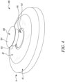
- FIG. 4 illustrates a schematic side view of the cover 100 having an opening 110.
- the inner area "A2" includes the opening 110 allowing water, particularly rainwater to pass through the cover 100.
- the opening 110 has a round cross-section.
- the opening 110 has a seating surface 112 at the circumference of the opening 110.
- the seating surface 112 is used to seat a movable guard 120 provided with the opening 110.
- the movable guard 120 may be removably coupled to the cover 100, or to the opening 110 in the inner area "A2" of the cover 100.
- the movable guard 120 is formed in one piece or preferably by at least two pieces that are connected together (for example via a snap fit).
- the movable guard 120 includes a body portion 122 and a cap portion 124.
- the body portion 122 as well as the cap portion 124 preferably has a circular or round cross-section, but can as well have any other shape.
- the cap portion 124 overlays the body portion 122 and further extends beyond the body portion 122. In other words, cap portion 124 has a larger diameter than the body portion 122. Further, the diameter of the body portion 122 is marginally less than the inner diameter of the seating surface 112.
- the cap portion 124 may be thick enough such that the cap portion 124 may be gripped by the user even when the cap portion 124 is seated on the seating surface 112.
- the movable guard 120 may be configured to be movable in a vertical direction, i.e., near or far to a ground surface when installed on the cover 100 of the water reservoir.
- FIG. 5 illustrates a schematic side view of the cover 100 having the opening 110 in a closed position.
- the cover 100 includes the inner area "A2" having the initial non-deformed shape " P1 ", which is the convex shape " P1 ", or the dome-like shape in respect to the outer area " A1 " of the circumference of the cover 100.
- the opening 110 is completely covered by the movable guard 120 such that no rainwater, or contaminant may enter the water reservoir.
- the cap portion 124 of the movable guard 120 is visible from outside.
- the body portion 122 is completely inside the cover 100 of the water reservoir.
- FIG. 6 illustrates a schematic side view of the cover 100 having the opening 110 in a partially open position.
- the cover 100 includes the inner area "A2" having the deformed shape “P2", which is the concave shape “P2", or the funnel or the basin like shape in respect to the outer area " A1 " of the circumference of the cover 100.
- the opening 110 is only partially covered by the movable guard 120 such that the rainwater may enter the water reservoir to fill the rainwater for further applications.
- the rainwater may enter the water reservoir via the gap between the body portion 122 and the seating surface 112 which is due to the difference in diameter of the body portion 122 and the seating surface 112 as the diameter of the body portion 122 is marginally less than the inner diameter of the seating surface.
- the rainwater falls on the concave shape "P2", or the funnel or the basin like shape of the inner area "A2" and slants towards the movable guard 120 which partially covers the opening 110 and then via the gap between the body portion 122 and the seating surface 112 falls in the water reservoir.
- the cap portion 124 of the movable guard 120 is fully visible from outside and the body portion 122 of the movable guard 120 is only partially visible from outside.
- the body portion 122 is only partially inside the cover 100 of the water reservoir.
- the partially open position of the opening 110 may be achieved by applying a pulling force to the movable guard 120.
- the pulling force may be applied using the hands of the user.
- a pushing force may be applied, for example using the hands of the user.
- the movable guard 120 may include a filter filtering the water, particularly rainwater that passes through the cover 100.
- the filter may be housed in the body portion 122 of the movable guard 120 or may be annularly attached to the circumference of the body portion 122. The rainwater entering the water reservoir may first pass through the filter in the movable guard 120.
- FIG. 7 illustrates a perspective view of the cover 100 without the movable guard 120.
- the cover 100 has the area “A” of the cover 100.
- the area “A” of cover 100 includes the outer area “ A1 " and the inner area “A2".
- the outer area “A1” is at the circumference of the cover 100.
- the inner area “A2” is inside the outer area “ A1 " and has the initial convex shape " P1 ".
- the marginal gap between the outer area “ A1 " and the inner area “A2” is bridged by the crossing area "A3".
- there is the opening 110 having the seating surface 112 at the circumference of the opening 110 for the movable guard 120 to be seated.
- FIG. 8 illustrates a perspective view of the cover 100 having the opening 110 in the closed position.
- the cover 100 includes the inner area “A2" having the initial non-deformed shape " P1 ", which is the convex shape " P1 ", or the dome-like shape in respect to the outer area "A1" of the circumference of the cover 100.
- the cover 100 further includes the crossing area "A3" between the outer area "A1” and the inner area "A2".
- the opening 110 is completely covered by the movable guard 120.
- only the cap portion 124 of the movable guard 120 is visible from outside while the body portion 122 is completely inside the cover 100 of the water reservoir.
- FIG. 9 illustrates a perspective view of the cover 100 having the opening 110 in the partially open position.
- the cover 100 includes the inner area “A2" having the deformed shape “P2” , which is the concave shape “P2", or the funnel or the basin like shape in respect to the outer area " A1 " of the circumference of the cover 100.
- the concave shape “P2” is obtainable due to the overall shape of the cover 100 along with flexible thermoplastic material of the inner area “A2” by applying force of hands to the inner area “A2” when the inner area “A2” is in convex shape " P1 " in respect to the outer area " A1 " of the cover 100.
- the opening 110 is only partially covered by the movable guard 120 and the water reservoir may be filled with rainwater.
Landscapes
- Engineering & Computer Science (AREA)
- Environmental & Geological Engineering (AREA)
- Health & Medical Sciences (AREA)
- Life Sciences & Earth Sciences (AREA)
- Hydrology & Water Resources (AREA)
- Public Health (AREA)
- Water Supply & Treatment (AREA)
- Sewage (AREA)
Abstract
A cover (100) of a water reservoir has an area (A) that includes an outer area (A1) at the circumference of the cover (100) and an inner area (A2) inside the outer area (A1). The inner area (A2) is not in contact with the outer area (A1). Further, the inner area (A2) and the outer area (A1) are connected to each other via a crossing area (A3) disposed in-between the inner area (A2) and the outer area (A1). The cover (100) of the water reservoir is characterized in that the inner area (A2) is flexible and is configured to be moved to exhibit at least two different shapes (P1, P2). Further, the inner area (A2) includes an opening (110) to allow water to pass through the cover (100).
Description
- The present disclosure relates to a cover for a water reservoir that may prevent contamination of water, particularly rainwater stored inside the water reservoir from debris, or other unwanted elements present in a surrounding environment.
- A water reservoir may be used to collect and store rainwater runoff, typically from rooftops via downpipes. The water reservoir may be installed to make use of rainwater for further applications, such as, watering gardens, agriculture, flushing toilets, in washing machines, washing cars, and for drinking, especially when other water supplies are unavailable, expensive, or of poor quality, and when adequate care is taken that the water is not contaminated and is adequately filtered. The water reservoir may be covered by a cover to prevent contamination of rainwater stored inside the water reservoir from debris, or other unwanted elements present in a surrounding environment.
- The water reservoir may be filled with rainwater in two well-known ways. In one way, a flap in the downpipe may be used to fill the water reservoir. However, in this way, the cover of the water reservoir may be required to be taken off and thus, debris, or other unwanted elements may enter the water reservoir and contaminate the stored rainwater. Further, in another way, a fixed inverter may be installed to permanently connect the punctured downpipe with an upper mantle surface of the water reservoir via a hose or pipe connection. In this way, the cover may always stay on top of the water reservoir and substantially prevent the rainwater stored inside the water reservoir from contamination. Further, the cover may have a convex dome shape so that dirt and unwanted rainwater may flow off. The dome shape may also allow more physical stability for the cover surface. However, there may be a requirement of an improved apparatus for filling the water reservoir with rainwater without compromising with the quality of rainwater ingested, ergonomics of operation, simplicity, and economics of construction.
- An example of an improved apparatus for filling the water reservoir with rainwater is provided in Chinese Utility Patent
CN 211,948,661 U (hereinafter referred to as '661 reference). The '661 reference provides a rain gauge barrel that is associated with several movable aprons. The surface of each of the aprons is divided into two parts that are angularly arranged to each other. One part of the apron is a dust cover part, and the other part is a funnel part. The aprons are moved between two positions with the help of telescopic links mounted between each of the aprons and an outer surface of the rain gauge barrel. In first position, the telescopic links are telescoped in and the dust-cover parts of all the aprons are adjacent to each other and cover the rain gauge barrel. In this position, the funnel parts of the aprons are close by the outer walls of the rain gauge barrel. In second position, the telescopic links are telescoped out and thereby make the dust cover parts to move into the rain gauge barrel, while the funnel parts move above the rain gauge barrel adjacent to each other to form a funnel that funnels the rain and directs it into the rain gauge barrel. Thus, in the first position, the rain gauge barrel is fully covered while in the second position the rainwater is directed via the aprons into the rain gauge barrel. - In view of the above, it is an objective of the present invention to solve or at least reduce the drawbacks discussed above. The objective is at least partially achieved by the cover of a water reservoir.
- According to an aspect of the present invention, the cover of the water reservoir has an area of cover. The area of the cover includes an outer area at a circumference of the cover and an inner area inside the outer area. The inner area is not in contact with the outer area and a crossing area is disposed in-between the inner area and the outer area. The cover of the water reservoir is characterized in that the inner area is flexible and is configured to be moved to exhibit at least two different shapes. Further, the inner area includes an opening allowing water to pass through the cover.
- Thus, the present disclosure provides an improved design of the cover for the water reservoir. The cover may advantageously allow filling of the water reservoir with rainwater without having to take off the cover from the water reservoir. The cover may prevent contamination of the stored or collected rainwater in the water reservoir. The cover may be suitable for installation with a fixed inverter to allow filling of the water reservoir with rainwater. The cover may also be suitable to allow filling of the water reservoir with rainwater using a flap in a downpipe. The flexibility of the inner area of the cover may allow the inner area of the cover to assume multiple shapes relative to the outer area of the cover such that the cover may be versatile enough to allow filling of the water reservoir with rainwater in any of the traditionally known way. The flexibility of the inner area of the cover may further allow the inner area of the cover to assume the shape of a funnel to collect the rainwater or assume the shape of a dome that may provide slope to let go off any debris, or dirt on a surface of the cover. Further, the cover may be simple and ergonomic in use and may be deformed to various required shapes simply by force of hands of a user. Further, the opening in the cover may allow installation of various apparatuses, such as the fixed inverter, or a filer assembly to further facilitate easy and substantially contaminant free filling of the rainwater in the water reservoir. Further, the cover may be simple in construction and easy to manufacture.
- The cover of the water reservoir has an area of cover according to the present invention. This may denote that the area of the cover is a body of the cover that is divided into three parts, namely the outer area, the crossing area, and the inner area such that that the inner area is inside the outer area. Further, the crossing area is a bridge portion between the outer area and the inner area to bridge the gap between the outer area and the inner area.
- According to an exemplary embodiment of the invention, the outer area, the crossing area, and the inner area may be integrally formed with any method well-suited in the art using different or similar materials without departing from the scope of the present invention. However, the outer area, the crossing area, and the inner area may be separately formed, and then bonded using known techniques such as, but not limited to, gluing, etc., to form one single cover. In any of the above cases, the different parts or areas of the cover may not be intended for separation once the cover may be operational.
- According to an exemplary embodiment of the invention, the outer area may be specially shaped such as to provide a comfortable gripping surface to the user. For example, the surface may have a series of crests and troughs. Further, the outer area may be able to dispose of or run off any debris, or dirt on its surface via force of gravity. Further, the outer area may be shaped corresponding to the shape of the water reservoir for aesthetic appeal and uniformity.
- According to an exemplary embodiment of the invention, the outer area may be provided with an outlet opening, such that the stored or collected rainwater may be pumped off form the outlet opening using a hose, or the like for further applications, such as, but not limited to, gardening, car-washing, and firefighting.
- According to an exemplary embodiment of the invention, the opening allowing passage of water, particularly rainwater, may be formed at the center of the cover, or the center of the inner area. However, the opening allowing passage of water may also be formed offset to the center of the inner area. Further, there may be multiple openings allowing passage of water formed or carved into the inner area of the cover. Further, the opening allowing passage of water may be pre-formed with the cover in a factory during manufacturing with an additional option to form or carve out more openings as per the user requirement after the purchase of the cover. Further, the opening allowing passage of water may conventionally have circular cross-section or shape but may have any other shape and size without limiting the scope of the present invention.
- According to an exemplary embodiment of the invention, the opening is provided with a movable guard. The movable guard may be configured to be movable in a vertical direction, i.e., near or far to the ground surface when installed on the cover of the water reservoir. Further, the movable guard may be configured to guard the stored or collected rainwater against contaminants or impurities in the surroundings of the water reservoir. The movable guard may completely align with the opening in the inner area when the water reservoir is not being filled with rainwater. Further, the movable guard may be substantially moved in vertical direction relative to the inner area when the water reservoir is required to be filled with rainwater. Further, the shape of the movable guard may correspond to the shape of the opening in the inner area.
- According to an exemplary embodiment of the invention, the movement of the movable guard may take place due to a push or pull force of the hands of the user. However, the movement of the movable guard may take place due to rotational force imparted to the movable guard such that the movable guard is rotated like a screw to move towards or away from the ground surface in the vertical direction.
- According to an exemplary embodiment of the invention, the movable guard is removable from the cover. The movable guard may be removable from the cover to allow installation of inlet hoses, or pipes with the opening in the inner area such that the inlet hoses, or pipes may permanently connect the downpipe with the water reservoir. Further, the movable guard may be removable to allow occasional inspection of the contents of the water reservoir. Further, the movable guard may be removable to allow easy servicing of the movable guard in case of damage, and the like.
- According to an exemplary embodiment of the invention, the movable guard includes a filter filtering the water that passes through the cover. The movable guard may advantageously house the filter to filter out the contaminants from the incoming rainwater when the water reservoir is being filled. The filter may be a surface filter made of closely woven fabric or treated paper with a uniform pore size. Further, the filter may be a depth filter made of layers of fabric or fibers, which provide many tortuous paths for the water to flow through. For example, the filter may be of the 5-micron, woven mesh, micronic, porous metal, or magnetic type.
- According to an exemplary embodiment of the invention, the inner area is configured to be moved to exhibit a concave shape and a convex shape in respect to the outer area of the circumference of the cover. The inner area may be moved to the convex or dome shape when the fixed inverter may be utilized to aid filling of rainwater in the water reservoir. Further, the inner area may be moved to the concave or basin like shape when the flap in the downpipe may be utilized to aid filling of rainwater in the water reservoir. The movement of the inner area from the convex shape to the concave shape may be configured to be tool-less. The movement of the inner area from the convex shape to the concave shape may be executed by force of hands of the user.
- According to an exemplary embodiment of the invention, the inner area is formed of a polypropylene material. The inner area may be formed from polypropylene or any other similar material, which may be flexible enough to be deformed from one shape to the other and may advantageously regain the original shape on its own in absence of any external force.
- According to an exemplary embodiment of the invention, a thickness of the crossing area is less than a thickness of the inner area and a thickness of the outer area. The shape of the cover thus formed along with the flexible material of the inner area may allow the inner area to assume at least two different shapes.
- According to an exemplary embodiment of the invention, the thickness of the inner area is substantially equal to the thickness of the outer area. However, the thickness of the inner area may be different than the thickness of the outer area. Particularly, the thickness of the inner area may be less than the thickness of the outer area.
- According to a further aspect of the present invention, the water reservoir includes the cover. The cover is mounted on top of the water reservoir. The water reservoir may be any kind of fixed or portable installation that may be configured to store rainwater for further domestic and industrial applications. For example, the water reservoir may be a cylindrical water tank commonly used in a household. However, the water reservoir of the present invention may be equally relevant or useful for collecting and storing any other fluid, particularly liquid fluid. Before discussing the invention with the help of the drawings the invention will be briefly discussed in general. A cover is designed to be suitable for both types of installation, i.e., a classical flap in a downpipe and an installation of a fixed inverter, which may permanently connect a punctured downpipe with an upper mantle surface of the water reservoir via a hose or pipe connection. In both cases, the cover may always stay closed on the water reservoir so that impurification of the collected rainwater is permanently avoided. The cover may initially be domed with a convex shape. In this condition, the cover may be suitable for the installation with the fixed inverter. Further, the cover may typically be made of polypropylene or similar material, which has very flexible material characteristics. Further, due to a defined, circumferential kinking groove at an outer area of the cover surface, the cover may be simply plopped from a convex to a concave shape by a simple push onto the surface with both hands. Further, there may be no constructive elements needed but just the material in combination with the shape that may allow for this plopping function. Further, the cover may be shaped just like a basin when in concave shape. Furthermore, a circular opening may be provided in the center of the cover that may allow for the rainwater to enter the water reservoir. This circular opening may further include a movable guard which may be pulled to open or pushed to close. Optionally, a filter may be integrated into the movable guard in order to prevent impurification of the collected rainwater.
- The cover according to the present invention may be suitable for two different applications, or installations as described above. The cover according to the present invention may allow clean and mosquito free rainwater collection for both applications or installations. The cover according to the present invention may be extremely simple and intuitive modification of the already known covers in the related field without any constructive elements. The cover according to the present invention may be only one single piece of cover.
- According to an exemplary embodiment of the invention, the plopping principle of the cover may allow a switch from the convex to the concave cover shape with surpassing simplicity and intuition.
- Other features and aspects of this invention will be apparent from the following description and the accompanying drawings.
- The invention will be described in more detail with reference to the enclosed drawings, wherein:
-
FIG. 1 illustrates a schematic view of a cover, in accordance with an exemplary embodiment of the present disclosure; -
FIG. 2 illustrates a schematic side view of a cover, in accordance with an exemplary embodiment of the present disclosure; -
FIG. 3 illustrates another schematic side view of a cover, in accordance with an exemplary embodiment of the present disclosure; -
FIG. 4 illustrates a schematic side view of a cover having an opening, in accordance with an exemplary embodiment of the present disclosure; -
FIG. 5 illustrates a schematic side view of a cover having an opening covered by a movable guard, in accordance with an exemplary embodiment of the present disclosure; -
FIG. 6 illustrates a schematic side view of a cover having an opening partially covered by a movable guard, in accordance with an exemplary embodiment of the present disclosure; -
FIG. 7 illustrates a perspective view of a cover without a movable guard, in accordance with an exemplary embodiment of the present disclosure; -
FIG. 8 illustrates a perspective view of a cover having an opening covered by a movable guard, in accordance with an exemplary embodiment of the present disclosure; and -
FIG. 9 illustrates a perspective view of a cover having an opening partially covered by a movable guard, in accordance with an exemplary embodiment of the present disclosure. - The present invention will be described more fully hereinafter with reference to the accompanying drawings, in which example embodiments of the invention incorporating one or more aspects of the present invention are shown. This invention may, however, be embodied in many different forms and should not be construed as limited to the embodiments set forth herein; rather, these embodiments are provided so that this disclosure will be thorough and complete, and will fully convey the scope of the invention to those skilled in the art. For example, one or more aspects of the present invention may be utilized in other embodiments and even other types of structures and/or methods. In the drawings, like numbers refer to like elements.
- Certain terminology is used herein for convenience only and is not to be taken as a limitation on the invention. For example, "upper", "lower", "front", "rear", "side", "longitudinal", "lateral", "transverse", "upwards", "downwards", "forward", "backward", "sideward", "left," "right," "horizontal," "vertical," "upward", "inner", "outer", "inward", "outward", "top", "bottom", "higher", "above", "below", "central", "middle", "intermediate", "between", "end", "adjacent", "proximate", "near", "distal", "remote", "radial", "circumferential", or the like, merely describe the configuration shown in the Figures. Indeed, the components may be oriented in any direction and the terminology, therefore, should be understood as encompassing such variations unless specified otherwise.
-
FIG. 1 illustrates a schematic view of acover 100 for covering a water reservoir according to an exemplary embodiment of the present invention. The water reservoir includes thecover 100 for mounting on top of the water reservoir. Thecover 100 of the water reservoir has an area "A" of thecover 100. The area "A" ofcover 100 includes an outer area "A1" and an inner area "A2". The outer area "A1" is at a circumference of thecover 100. The outer area "A1" has a thickness "T1". Further, the inner area "A2" is inside the outer area "A1" and is formed from a polypropylene material, which is a flexible thermoplastic. The inner area "A2" has a thickness "T2". The inner area "A2" is not in contact with the outer area "A1" There is a marginal gap between the outer area "A1" and the inner area "A2". The marginal gap between the outer area "A1" and the inner area "A2" is bridged by a crossing area "A3". In other words, the crossing area "A3" is disposed in-between the inner area "A2" and the outer area "A1". The crossing area "A3" has a thickness "T3". - The thickness "T3" of the crossing area "A3" is less than the thickness "T2" of the inner area "A2" and the thickness "T1" of the outer area "A1". In other words, the thickness "T3" < the thickness "T1", and the thickness "T3" < the thickness "T2". Further, the thickness "T1" of the outer area "A1" is substantially equal to the thickness "T2" of the inner area "A2". The shape of the
cover 100 thus formed along with flexible thermoplastic material of the inner area "A2" allows the inner area "A2" to be moved to exhibit at least two different shapes "P1, P2". - The inner area "A2" is configured to be moved to exhibit a concave shape "P2" and a convex shape "P1", as shown in
FIG. 1 in respect to the outer area "A1" of the circumference of thecover 100. The movement of the inner area "A2" from the convex shape "P1" to the concave shape "P2" may be configured to be tool-less. The movement of the inner area "A2" from the convex shape "P1" to the concave shape "P2" may be executed by force of hands of a user. -
FIG. 2 illustrates a schematic side view of thecover 100. Thecover 100 includes the inner area "A2" having an initial non-deformed shape "P1", which is the convex shape "P1", or a dome-like shape in respect to the outer area "A1" of the circumference of thecover 100. -
FIG. 3 illustrates another schematic side view of thecover 100. Thecover 100 includes the inner area "A2" having a deformed shape "P2", which is the concave shape "P2", or a funnel or a basin like shape in respect to the outer area "A1" of the circumference of thecover 100. -
FIG. 4 illustrates a schematic side view of thecover 100 having anopening 110. The inner area "A2" includes theopening 110 allowing water, particularly rainwater to pass through thecover 100. Theopening 110 has a round cross-section. Theopening 110 has aseating surface 112 at the circumference of theopening 110. Theseating surface 112 is used to seat amovable guard 120 provided with theopening 110. Themovable guard 120 may be removably coupled to thecover 100, or to theopening 110 in the inner area "A2" of thecover 100. - The
movable guard 120 is formed in one piece or preferably by at least two pieces that are connected together (for example via a snap fit). Themovable guard 120 includes abody portion 122 and acap portion 124. Thebody portion 122 as well as thecap portion 124 preferably has a circular or round cross-section, but can as well have any other shape. Thecap portion 124 overlays thebody portion 122 and further extends beyond thebody portion 122. In other words,cap portion 124 has a larger diameter than thebody portion 122. Further, the diameter of thebody portion 122 is marginally less than the inner diameter of theseating surface 112. - Further, a portion of the
cap portion 124 that extends beyond thebody portion 122 seats on theseating surface 112 when themovable guard 120 is removably coupled with thecover 100. Thecap portion 124 may be thick enough such that thecap portion 124 may be gripped by the user even when thecap portion 124 is seated on theseating surface 112. Further, themovable guard 120 may be configured to be movable in a vertical direction, i.e., near or far to a ground surface when installed on thecover 100 of the water reservoir. -
FIG. 5 illustrates a schematic side view of thecover 100 having the opening 110 in a closed position. Thecover 100 includes the inner area "A2" having the initial non-deformed shape "P1", which is the convex shape "P1", or the dome-like shape in respect to the outer area "A1" of the circumference of thecover 100. In the closed position of theopening 110, theopening 110 is completely covered by themovable guard 120 such that no rainwater, or contaminant may enter the water reservoir. Further, in the closed position of theopening 110, only thecap portion 124 of themovable guard 120 is visible from outside. Thebody portion 122 is completely inside thecover 100 of the water reservoir. -
FIG. 6 illustrates a schematic side view of thecover 100 having the opening 110 in a partially open position. Thecover 100 includes the inner area "A2" having the deformed shape "P2", which is the concave shape "P2", or the funnel or the basin like shape in respect to the outer area "A1" of the circumference of thecover 100. In the partially open position of theopening 110, theopening 110 is only partially covered by themovable guard 120 such that the rainwater may enter the water reservoir to fill the rainwater for further applications. The rainwater may enter the water reservoir via the gap between thebody portion 122 and theseating surface 112 which is due to the difference in diameter of thebody portion 122 and theseating surface 112 as the diameter of thebody portion 122 is marginally less than the inner diameter of the seating surface. The rainwater falls on the concave shape "P2", or the funnel or the basin like shape of the inner area "A2" and slants towards themovable guard 120 which partially covers theopening 110 and then via the gap between thebody portion 122 and theseating surface 112 falls in the water reservoir. - Further, in the partially open position of the
opening 110, thecap portion 124 of themovable guard 120 is fully visible from outside and thebody portion 122 of themovable guard 120 is only partially visible from outside. Thebody portion 122 is only partially inside thecover 100 of the water reservoir. The partially open position of theopening 110 may be achieved by applying a pulling force to themovable guard 120. The pulling force may be applied using the hands of the user. Further, to move theopening 110 from the partially open position to the closed position, a pushing force may be applied, for example using the hands of the user. - Further, the
movable guard 120 may include a filter filtering the water, particularly rainwater that passes through thecover 100. The filter may be housed in thebody portion 122 of themovable guard 120 or may be annularly attached to the circumference of thebody portion 122. The rainwater entering the water reservoir may first pass through the filter in themovable guard 120. -
FIG. 7 illustrates a perspective view of thecover 100 without themovable guard 120. Thecover 100 has the area "A" of thecover 100. The area "A" ofcover 100 includes the outer area "A1" and the inner area "A2". The outer area "A1" is at the circumference of thecover 100. Further, the inner area "A2" is inside the outer area "A1" and has the initial convex shape "P1". There is a marginal gap between the outer area "A1" and the inner area "A2". The marginal gap between the outer area "A1" and the inner area "A2" is bridged by the crossing area "A3". Further, there is theopening 110 having theseating surface 112 at the circumference of theopening 110 for themovable guard 120 to be seated. -
FIG. 8 illustrates a perspective view of thecover 100 having the opening 110 in the closed position. Thecover 100 includes the inner area "A2" having the initial non-deformed shape "P1", which is the convex shape "P1", or the dome-like shape in respect to the outer area "A1" of the circumference of thecover 100. Thecover 100 further includes the crossing area "A3" between the outer area "A1" and the inner area "A2". In the closed position of theopening 110, theopening 110 is completely covered by themovable guard 120. Further, in the closed position of theopening 110, only thecap portion 124 of themovable guard 120 is visible from outside while thebody portion 122 is completely inside thecover 100 of the water reservoir. -
FIG. 9 illustrates a perspective view of thecover 100 having the opening 110 in the partially open position. Thecover 100 includes the inner area "A2" having the deformed shape "P2", which is the concave shape "P2", or the funnel or the basin like shape in respect to the outer area "A1" of the circumference of thecover 100. The concave shape "P2" is obtainable due to the overall shape of thecover 100 along with flexible thermoplastic material of the inner area "A2" by applying force of hands to the inner area "A2" when the inner area "A2" is in convex shape "P1" in respect to the outer area "A1" of thecover 100. Further, in the partially open position of theopening 110, theopening 110 is only partially covered by themovable guard 120 and the water reservoir may be filled with rainwater. - In the drawings and specification, there have been disclosed exemplary embodiments and examples of the invention and, although specific terms are employed, they are used in a generic and descriptive sense only and not for the purpose of limitation of the scope of the invention being set forth in the following claims.
-
- 100
- Cover
- 110
- Opening
- 112
- Seating Surface
- 120
- Movable Guard
- 122
- Body Portion
- 124
- Cap Portion
- A
- Area
- A1
- Outer Area
- A2
- Inner Area
- A3
- Crossing Area
- T1
- Thickness of outer area
- T2
- Thickness of inner area
- T3
- Thickness of crossing area
- P1
- Shape/ Convex Shape
- P2
- Shape/ Concave Shape
Claims (8)
- A cover (100) of a water reservoir with an area (A) of the cover (100) comprising:an outer area (A1) at a circumference of the cover (100),an inner area (A2) inside the outer area (A1),with the inner area (A2) not being in contact with the outer area (A1), and a crossing area (A3) in-between the inner area (A2) and the outer area (A1), characterized in that: the inner area (A2) is flexible and is configured to be moved to exhibit at least two different shapes (P1, P2),with the inner area (A2) comprising an opening (110) allowing water to pass through the cover (100).
- The cover (100) of the water reservoir of claim 1, wherein the opening (110) is provided with a movable guard (120).
- The cover (100) of the water reservoir of claim 2, wherein the movable guard (120) is removable from the cover (100).
- The cover (100) of the water reservoir of claims 2 or 3, wherein the movable guard (120) comprises a filter filtering the water that passes through the cover (100).
- The cover (100) of the water reservoir of claim 1, wherein the inner area (A2) is configured to be moved to exhibit a concave shape (P2) and a convex shape (P1) in respect to the outer area (A1) of the circumference of the cover (100).
- The cover (100) of the water reservoir of claims 1 or 5, wherein the inner area (A2) is formed of a polypropylene material.
- The cover (100) of the water reservoir of claim 1, wherein a thickness (T3) of the crossing area (A3) is less than a thickness (T2) of the inner area (A2) and a thickness (T1) of the outer area (A1).
- A water reservoir comprising a cover (100) according to one of the preceding claims, wherein the cover (100) is mounted on top of the water reservoir.
Priority Applications (1)
| Application Number | Priority Date | Filing Date | Title |
|---|---|---|---|
| EP23174926.8A EP4467730A1 (en) | 2023-05-23 | 2023-05-23 | A cover for a water reservoir |
Applications Claiming Priority (1)
| Application Number | Priority Date | Filing Date | Title |
|---|---|---|---|
| EP23174926.8A EP4467730A1 (en) | 2023-05-23 | 2023-05-23 | A cover for a water reservoir |
Publications (1)
| Publication Number | Publication Date |
|---|---|
| EP4467730A1 true EP4467730A1 (en) | 2024-11-27 |
Family
ID=86497480
Family Applications (1)
| Application Number | Title | Priority Date | Filing Date |
|---|---|---|---|
| EP23174926.8A Pending EP4467730A1 (en) | 2023-05-23 | 2023-05-23 | A cover for a water reservoir |
Country Status (1)
| Country | Link |
|---|---|
| EP (1) | EP4467730A1 (en) |
Citations (12)
| Publication number | Priority date | Publication date | Assignee | Title |
|---|---|---|---|---|
| US3326421A (en) * | 1965-11-12 | 1967-06-20 | Eastman Kodak Co | Retractable plastic bottle spout |
| US3730120A (en) * | 1971-03-01 | 1973-05-01 | Aquavoir Holding Co Sa | Method and apparatus of collecting rainwater |
| EP1862395A1 (en) * | 2006-05-30 | 2007-12-05 | Huhtamaki Consumer Packaging, Inc. | Condiment dispenser with collapsible spout |
| US20080034492A1 (en) * | 2002-05-30 | 2008-02-14 | Essig John R Jr | Systems and methods for harnessing resources |
| CN201339213Y (en) * | 2008-12-05 | 2009-11-04 | 陈国荣 | Foldable rainwater collecting device |
| ES1073766U (en) * | 2011-01-19 | 2011-02-10 | Meidinn, S.L.P | Device for the collection of rainwater (Machine-translation by Google Translate, not legally binding) |
| JP2012057319A (en) * | 2010-09-07 | 2012-03-22 | Moki Seisakusho:Kk | Rainwater collecting device |
| CN204826048U (en) * | 2015-06-15 | 2015-12-02 | 天津市百福农业科技有限公司 | Rain water collecting device for agricultural irrigation |
| CN206061715U (en) * | 2016-07-01 | 2017-04-05 | 北京碧水源生态环境科技有限公司 | A kind of treegarden irrigation header tank |
| CN211948661U (en) | 2020-02-20 | 2020-11-17 | 南京南测仪器技术有限公司 | Rainfall collection device |
| CN212561711U (en) * | 2020-05-27 | 2021-02-19 | 内蒙古建筑职业技术学院 | Gardens building rainwater collection device |
| CN113802642A (en) * | 2021-10-21 | 2021-12-17 | 洛阳德野专用车辆有限公司 | Car as a house rainwater collection system and rainwater collection method |
-
2023
- 2023-05-23 EP EP23174926.8A patent/EP4467730A1/en active Pending
Patent Citations (12)
| Publication number | Priority date | Publication date | Assignee | Title |
|---|---|---|---|---|
| US3326421A (en) * | 1965-11-12 | 1967-06-20 | Eastman Kodak Co | Retractable plastic bottle spout |
| US3730120A (en) * | 1971-03-01 | 1973-05-01 | Aquavoir Holding Co Sa | Method and apparatus of collecting rainwater |
| US20080034492A1 (en) * | 2002-05-30 | 2008-02-14 | Essig John R Jr | Systems and methods for harnessing resources |
| EP1862395A1 (en) * | 2006-05-30 | 2007-12-05 | Huhtamaki Consumer Packaging, Inc. | Condiment dispenser with collapsible spout |
| CN201339213Y (en) * | 2008-12-05 | 2009-11-04 | 陈国荣 | Foldable rainwater collecting device |
| JP2012057319A (en) * | 2010-09-07 | 2012-03-22 | Moki Seisakusho:Kk | Rainwater collecting device |
| ES1073766U (en) * | 2011-01-19 | 2011-02-10 | Meidinn, S.L.P | Device for the collection of rainwater (Machine-translation by Google Translate, not legally binding) |
| CN204826048U (en) * | 2015-06-15 | 2015-12-02 | 天津市百福农业科技有限公司 | Rain water collecting device for agricultural irrigation |
| CN206061715U (en) * | 2016-07-01 | 2017-04-05 | 北京碧水源生态环境科技有限公司 | A kind of treegarden irrigation header tank |
| CN211948661U (en) | 2020-02-20 | 2020-11-17 | 南京南测仪器技术有限公司 | Rainfall collection device |
| CN212561711U (en) * | 2020-05-27 | 2021-02-19 | 内蒙古建筑职业技术学院 | Gardens building rainwater collection device |
| CN113802642A (en) * | 2021-10-21 | 2021-12-17 | 洛阳德野专用车辆有限公司 | Car as a house rainwater collection system and rainwater collection method |
Similar Documents
| Publication | Publication Date | Title |
|---|---|---|
| US9732526B2 (en) | System of components which, assembled, form a rainwater separator for a downpipe | |
| WO1997015371A1 (en) | Bag filter and retainer therefor | |
| AU2001266253A1 (en) | Swimming pool cleaner | |
| US7086536B2 (en) | Fluid filtering device with scraping element | |
| EP2224064A1 (en) | Rainwaterfiltersystem | |
| JP6078720B2 (en) | Piping equipment | |
| CN210631778U (en) | Water purifier with multiple filtration | |
| JP5137037B2 (en) | Rainwater storage tank | |
| JP6238167B2 (en) | Drain | |
| CN102392479B (en) | Water tank drainer | |
| JP2009167666A (en) | Rainwater using device | |
| CN217139538U (en) | Filter that cooperation intelligent closestool used | |
| US5429019A (en) | Plug manipulator tool for swimming pool skimmer | |
| CN104164906A (en) | Ultrasonic cleaning and draining integrated machine | |
| US6082395A (en) | Fluid flow regulator | |
| CN202298802U (en) | Water-tank dewatering device | |
| WO2007147228A1 (en) | Distributor for domestic water filters | |
| US12467241B2 (en) | Rainwater reservoir | |
| CN114305248A (en) | Dirty device of storage of scrubber | |
| CN101201122B (en) | Ball valve | |
| US4262692A (en) | Bell trap and check valve combination | |
| JP7750465B2 (en) | Drain cover | |
| JP5048467B2 (en) | Rainwater removal device | |
| KR200331013Y1 (en) | A filter for sink waterway | |
| JP4888246B2 (en) | Drain valve |
Legal Events
| Date | Code | Title | Description |
|---|---|---|---|
| PUAI | Public reference made under article 153(3) epc to a published international application that has entered the european phase |
Free format text: ORIGINAL CODE: 0009012 |
|
| STAA | Information on the status of an ep patent application or granted ep patent |
Free format text: STATUS: REQUEST FOR EXAMINATION WAS MADE |
|
| 17P | Request for examination filed |
Effective date: 20231214 |
|
| AK | Designated contracting states |
Kind code of ref document: A1 Designated state(s): AL AT BE BG CH CY CZ DE DK EE ES FI FR GB GR HR HU IE IS IT LI LT LU LV MC ME MK MT NL NO PL PT RO RS SE SI SK SM TR |