EP4467696A1 - Weft yarn tensioning device for air jet loom - Google Patents
Weft yarn tensioning device for air jet loom Download PDFInfo
- Publication number
- EP4467696A1 EP4467696A1 EP24157520.8A EP24157520A EP4467696A1 EP 4467696 A1 EP4467696 A1 EP 4467696A1 EP 24157520 A EP24157520 A EP 24157520A EP 4467696 A1 EP4467696 A1 EP 4467696A1
- Authority
- EP
- European Patent Office
- Prior art keywords
- valve
- sub tank
- weft yarn
- tube
- tank
- Prior art date
- Legal status (The legal status is an assumption and is not a legal conclusion. Google has not performed a legal analysis and makes no representation as to the accuracy of the status listed.)
- Granted
Links
Images


Classifications
-
- D—TEXTILES; PAPER
- D03—WEAVING
- D03D—WOVEN FABRICS; METHODS OF WEAVING; LOOMS
- D03D47/00—Looms in which bulk supply of weft does not pass through shed, e.g. shuttleless looms, gripper shuttle looms, dummy shuttle looms
- D03D47/28—Looms in which bulk supply of weft does not pass through shed, e.g. shuttleless looms, gripper shuttle looms, dummy shuttle looms wherein the weft itself is projected into the shed
- D03D47/30—Looms in which bulk supply of weft does not pass through shed, e.g. shuttleless looms, gripper shuttle looms, dummy shuttle looms wherein the weft itself is projected into the shed by gas jet
- D03D47/3066—Control or handling of the weft at or after arrival
- D03D47/308—Stretching or holding the weft
-
- D—TEXTILES; PAPER
- D03—WEAVING
- D03D—WOVEN FABRICS; METHODS OF WEAVING; LOOMS
- D03D47/00—Looms in which bulk supply of weft does not pass through shed, e.g. shuttleless looms, gripper shuttle looms, dummy shuttle looms
- D03D47/28—Looms in which bulk supply of weft does not pass through shed, e.g. shuttleless looms, gripper shuttle looms, dummy shuttle looms wherein the weft itself is projected into the shed
- D03D47/30—Looms in which bulk supply of weft does not pass through shed, e.g. shuttleless looms, gripper shuttle looms, dummy shuttle looms wherein the weft itself is projected into the shed by gas jet
- D03D47/3026—Air supply systems
- D03D47/3053—Arrangements or lay out of air supply systems
-
- D—TEXTILES; PAPER
- D03—WEAVING
- D03D—WOVEN FABRICS; METHODS OF WEAVING; LOOMS
- D03D49/00—Details or constructional features not specially adapted for looms of a particular type
- D03D49/60—Construction or operation of slay
Definitions
- the present invention relates to a weft yarn tensioning device for an air jet loom.
- a weft yarn tensioning device for an air jet loom disclosed in Japanese Patent Application Publication No. 2014-231649 includes a stretch nozzle, an air tank, and an on-off valve.
- the stretch nozzle is attached to a sley fixed to a rocking shaft.
- the stretch nozzle is located on a downstream side of a sub nozzle for weft insertion in a weft insertion direction, and the position of the stretch nozzle is adjustable in the weft insertion direction in accordance with a change of a width of woven fabric.
- the air tank is provided on a part of a frame of the air jet loom.
- the on-off valve is attached to the air tank and connected to the stretch nozzle through a flexible air supply tube.
- the stretch nozzle is far from the on-off valve, so that pressure loss between the stretch nozzle and the on-off valve causes an air injection pressure from the stretch nozzle to decrease.
- the on-off valve may be disposed near the stretch nozzle to reduce the pressure loss between the stretch nozzle and the on-off valve.
- the on-off valve remains far from the air tank, and thus, a tube connecting the on-off valve to the air tank is required to have a large diameter in order to reduce pressure loss between the on-off valve and the air tank.
- the tube connecting the on-off valve and the air tank has the large diameter, the on-off valve is difficult to move in accordance with a positional adjustment of the stretch nozzle because the large diameter tube has high stiffness.
- a weft yarn tensioning device for an air jet loom including a pair of side frames, a rocking shaft that is supported by the side frames and rotatable in a reciprocating manner, a sley that swings together with the rocking shaft, and a profile reed that is provided in the sley and forms a weft yarn guide passage.
- the weft yarn tensioning device includes a stretch nozzle oriented toward the weft yarn insertion passage, the stretch nozzle being provided in the sley such that the stretch nozzle is movable in a weft insertion direction of a weft yarn, a main tank as a supply source of compressed air, the main tank being provided in the side frame close to the stretch nozzle of the pair of side frames, and an on-off valve connected to the stretch nozzle through a first air tube.
- the on-off valve is provided on an end portion of a temple base on a counter-weft insertion side.
- the temple base is supported by a supporting bar formed between the pair of side frames.
- a sub tank is provided on the end portion of the temple base on the counter-weft insertion side.
- the sub tank is smaller than the main tank, connected to the on-off valve, and connected to the main tank through a second air tube.
- an air jet loom 10 includes a pair of left and right side frames 11 and a rocking shaft 12 that is supported by the side frames 11 and rotatable in a reciprocating manner.
- a plurality of arms 12a is provided on the rocking shaft 12 and extends upward from the rocking shaft 12.
- a sley 13 is supported on upper ends of the arms 12a. The sley 13 swings together with the rocking shaft 12 by the reciprocating motion of the rocking shaft 12.
- the sley 13 has a supporting groove 14 into which a lower end of a profile reed 16 is inserted.
- the profile reed 16 forms a weft yarn guide passage 16a. That is, the profile reed 16 that forms the weft yarn guide passage 16a is provided in the sley 13.
- the lower end of the profile reed 16 is fixed by a wedge 17 inserted into the supporting groove 14.
- the profile reed 16 is formed of a lot of dents 18 arranged in a longitudinal direction of the sley 13. Upper ends of the dents 18 are held by an upper frame 19 of the profile reed 16.
- the air jet loom 10 includes a sub nozzle 20 disposed on a front surface side of the profile reed 16.
- the sub nozzle 20 is attached to a groove 13a formed in a sley 13 and movable along the groove 13a.
- a position of the sub nozzle 20 is adjustable in the longitudinal direction of the sley 13.
- the air jet loom 10 includes a weft yarn catching pipe 22.
- the weft yarn catching pipe 22 is disposed on a rear surface side of the profile reed 16.
- the weft yarn catching pipe 22 is fixed at a predetermined position in the longitudinal direction of the sley 13.
- the weft yarn catching pipe 22 is bent to have an L-shape.
- a short portion 22a of the weft yarn catching pipe 22 is disposed substantially at right angles to the profile reed 16.
- An inlet 22b is open at an end portion of the short portion 22a. The inlet 22b communicates with the weft yarn guide passage 16a.
- a long portion 22c of the weft yarn catching pipe 22 is disposed substantially in parallel with the profile reed 16.
- An outlet 22d is open at a rear end portion of the long portion 22c and is oriented to a downstream side in a weft insertion direction.
- the weft yarn insertion direction is a direction in which a weft yarn travels through the weft yarn guide passage 16a.
- Compressed air injected from an injection hole 31a of a stretch nozzle 31, which will be described later, is blown into the inlet 22b across the weft yarn guide passage 16a. The compressed air flows from the short portion 22a to the long portion 22c in the weft yarn catching pipe 22 while turning the corner of the substantially right angles, and flows out from the outlet 22d.
- the air jet loom 10 includes a supporting bar 23 formed between the pair of side frames 11.
- a temple device 60 for preventing crimp of woven fabric is provided on the supporting bar 23.
- the temple device 60 includes a temple base 61 and temple device main bodies 62 each provided on left and right sides of the temple base 61.
- the temple base 61 is a plate having a trapezoidal shape when viewed in a cross-section and is supported on an upper surface of the supporting bar 23.
- the temple base 61 is supported by the supporting bar 23 with a longitudinal direction of the temple base 61 coinciding with a longitudinal direction of the supporting bar 23.
- the temple device main bodies 62 are each provided in one end portion of the temple base 61 on a weft insertion side from which the weft yarn is inserted into the weft yarn guide passage 16a and in the other end portion of the temple base 61 on a counter-weft insertion side, which is a side opposite to the weft insertion side across the temple base 61, an illustration of the temple device main body 62 on the weft insertion side is omitted.
- the temple base 61 extends in a left and right direction of the air jet room 10. The following will describe the temple device main body 62 provided on the end portion of the temple base 61 on the counter-weft insertion side.
- the temple device main body 62 is movable in the longitudinal direction of the temple base 61 such that its attachment position to the temple base 61 is adjusted.
- the temple device main body 62 includes a temple bracket 63, a supporting bracket 65 integrated with the temple bracket 63, and a temple main body supported by the supporting bracket 65. An illustration of the temple main body is omitted.
- the temple device main body 62 also includes an attachment piece 64 integrated with the temple bracket 63. In the temple device main body 62, the temple bracket 63, the supporting bracket 65, and the temple main body which is not illustrated are integrated with each other.
- the attachment piece 64 of the temple device main body 62 is disposed so as to face a side surface of the temple base 61.
- the temple device main body 62 is positioned relative to the temple base 61 by screwing a bolt 67 inserted through the attachment piece 64 while the bolt 67 is pressed against the temple base 61.
- the temple device main body 62 is movable in the longitudinal direction of the temple base 61.
- a weft yarn tensioning device 30 for the airjet loom 10 includes the stretch nozzle 31, an on-off valve 32, a sub tank 33, and a main tank 34.
- the main tank 34 is provided in the side frame 11 located on the counter-weft insertion side of the pair of side frames 11.
- the main tank 34 stores compressed air at high pressure.
- the main tank 34 is a supply source from which the compressed air is supplied to the stretch nozzle 31.
- the stretch nozzle 31 is attached to the groove 13a formed in the sley 13.
- a position of the stretch nozzle 31 is adjustable along a longitudinal direction of the groove 13a. That is, the stretch nozzle 31 is provided in the sley 13 such that the stretch nozzle 31 is movable in the weft insertion direction of a weft yarn.
- the stretch nozzle 31 is provided such that the injection hole 31a of the stretch nozzle 31 faces the inlet 22b of the weft yarn catching pipe 22, and the stretch nozzle 31 is oriented toward the weft yarn guide passage 16a.
- the on-off valve 32 and the sub tank 33 are integrated with the temple device main body 62.
- a bracket 42 is fastened to the temple bracket 63.
- the bracket 42 has a first attachment piece 42a attached to the temple bracket 63, a second attachment piece 42b attached to the sub tank 33, and a third attachment piece 42c to which the on-off valve 32 is attached.
- the bracket 42 is formed by bending a plate material so that the first attachment piece 42a, the second attachment piece 42b, and the third attachment piece 42c are formed.
- the temple device main body 62, the on-off valve 32, and the sub tank 33 are integrated by the bracket 42.
- the on-off valve 32 and the sub tank 33 are also moved integrally with the temple device main body 62.
- the on-off valve 32 and the sub tank 33 are also provided on the temple base 61 through the temple device main body 62.
- the on-off valve 32 and the sub tank 33 are provided on the temple base 61.
- the on-off valve 32 is connected to the stretch nozzle 31 through a first air tube 51.
- the first air tube 51 is, for example, a flexible tube such as a resin hose.
- the first air tube 51 with extra length connects the stretch nozzle 31 to the on-off valve 32.
- the sub tank 33 is connected to the on-off valve 32 through a first joint 55 and a third air tube 53.
- the first joint 55 is connected to the sub tank 33.
- the third air tube 53 is, for example, a flexible tube such as a resin hose.
- the third air tube 53 with extra length connects the on-off valve 32 to the sub tank 33.
- the main tank 34 is provided in the side frame 11 on a side where the on-off valve 32 is attached to the temple device main body 62, that is, in the side frame 11 on the counter-weft insertion side, of the pair of side frames 11.
- the stretch nozzle 31 is provided near the on-off valve 32, and thus, the main tank 34 is provided in the side frame 11 close to the stretch nozzle 31 of the pair of side frames 11.
- the main tank 34 is connected to the sub tank 33 through the first joint 55 and a second air tube 52.
- the second air tube 52 includes a sub tank side tube 52a, a second joint 56, and a main tank side tube 52b.
- a first end of the sub tank side tube 52a is connected to the first joint 55, and a second end of the sub tank side tube 52a is connected to the second joint 56.
- a first end of the main tank side tube 52b is connected to the second joint 56, and a second end of the main tank side tube 52b is connected to the main tank 34.
- the sub tank side tube 52a is a flexible tube.
- the sub tank side tube 52a with extra length connects the first joint 55 to the second joint 56.
- the main tank side tube 52b is made of a steel tube, and a diameter of the main tank side tube 52b is larger than that of the sub tank side tube 52a.
- the main tank side tube 52b extends straight downward from the second joint 56, and is bent toward the main tank 34 near the second end of the main tank side tube 52b.
- the main tank side tube 52b is integrated with the side frame 11, and keeps a shape extending straight by itself due to stiffness of the main tank side tube 52b.
- the second joint 56 connected to the first end of the main tank side tube 52b is positioned at a predetermined position due to the stiffness of the main tank side tube 52b.
- the second joint 56 is located above the upper surface of the supporting bar 23 and near the temple base 61. Accordingly, this sub tank side tube 52a connecting the second joint 56 to the first joint 55 is disposed above the upper surface of the supporting bar 23. An extra length portion of the sub tank side tube 52a is also disposed above the upper surface of the supporting bar 23. The extra length portion of the sub tank side tube 52a is made short or long between the first joint 55 and the second joint 56 above the upper surface of the supporting bar 23. That is, the sub tank side tube 52a is a flexible tube disposed above the upper surface of the supporting bar 23.
- a length of the sub tank side tube 52a between the first joint 55 and the second joint 56 is set depending on a movable range of the temple device main body 62.
- the length of the sub tank side tube 52a is set such that the sub tank side tube 52a does not get strained and has some extra length even when the temple device main body 62 is moved to a position farthest from the side frame 11 in which the main tank 34 is provided.
- the compressed air at high pressure stored in the main tank 34 is supplied to the sub tank 33 through the main tank side tube 52b, the second joint 56, the sub tank side tube 52a, and the first joint 55.
- Pressure loss between the main tank 34 and the sub tank 33 is reduced due to the main tank side tube 52b with the large diameter as compared with a configuration in which the main tank side tube 52b and the sub tank side tube 52a have the same diameter.
- a flow passage R is formed of the third air tube 53, the first joint 55, the sub tank 33, and the second air tube 52 between the on-off valve 32 and the main tank 34.
- the sub tank 33 smaller than the main tank 34 is disposed on this flow passage R.
- the size of the sub tank 33 is set such that one air injection from the stretch nozzle 31 does not cause a pressure drop of a predetermined value or more.
- the on-off valve 32 when the on-off valve 32 opens, the compressed air stored in the sub tank 33 is supplied to the stretch nozzle 31 through the first air tube 51.
- the on-off valve 32 closes, the air flow to the first air tube 51 is shut off, so that the supply of the compressed air from the sub tank 33 to the stretch nozzle 31 is stopped and the compressed air is supplied from the main tank 34 to the sub tank 33 through the main tank side tube 52b and the sub tank side tube 52a until the next air injection. Accordingly, the compressed air is supplied from the main tank 34 to the sub tank 33 while the on-off valve 32 is closed, so that the sub tank 33 stores the compressed air at high pressure before the on-off valve 32 opens, similarly to the main tank 34.
- a weft yarn is inserted into the weft yarn guide passage 16a by a weft yarn insertion nozzle and the sub nozzle 20. Illustrations of the weft yarn and the weft yarn insertion nozzle are omitted.
- the on-off valve 32 opens.
- the compressed air in the sub tank 33 is supplied to the stretch nozzle 31 through the third air tube 53, the on-off valve 32, and the first air tube 51. Then, the compressed air is injected from the injection hole 31a of the stretch nozzle 31 in a direction perpendicular to the weft yarn guide passage 16a.
- the weft yarn in the weft yarn guide passage 16a is blown to the inlet 22b of the weft yarn catching pipe 22 by the compressed air.
- the compressed air is guided from the short portion 22a to the long portion 22c in the weft yarn catching pipe 22. Accordingly, after the weft yarn is bent at the right angles while being blown from the weft yarn guide passage 16a to the short portion 22a of the weft yarn catching pipe 22, the weft yarn is maintained in a bent state at the right angles while being blown from the short portion 22a to the long portion 22c in the weft yarn catching pipe 22 again.
- the inserted weft yarn is woven into woven fabric while being applied to a predetermined tension over an entire length of the weft yarn because the weft yarn is held by the profile reed 16, the stretch nozzle 31, and the weft yarn catching pipe 22.
- the position of the stretch nozzle 31 is adjusted along the longitudinal direction of the groove 13a formed in the sley 13.
- the position of the temple device main body 62 is also adjusted in accordance with the width of the woven fabric.
- the bolt 67 is screwed out from the attachment piece 64 to make the temple device main body 62 movable along the temple base 61.
- the position of the temple device main body 62 is adjusted such that the temple main body, which is not illustrated, is located at a position in accordance with the width of the woven fabric.
- the on-off valve 32 and the sub tank 33 are integrated with this temple device main body 62, so that the on-off valve 32 and the sub tank 33 are also moved integrally with the temple device main body 62 as the temple device main body 62 moves.
- the bolt 67 is inserted into the attachment piece 64 and screwed while pressed against the temple base 61.
- the on-off valve 32 and the sub tank 33 are provided on the end portion of the temple base 61 on the counter-weft insertion side.
- positions of the on-off valve 32 and the sub tank 33 are also adjusted.
- the on-off valve 32 is moved integrally with the sub tank 33, and thus, the third air tube 53 connecting the on-off valve 32 to the sub tank 33 is hardly stretched or slackened.
- a distance between the sub tank 33 and the main tank 34 varies. For example, when the sub tank 33 leaves the main tank 34, the sub tank side tube 52a with the extra length portion is stretched such that the extra length portion is shortened. This stretch of the sub tank side tube 52a allows the movement of the sub tank 33.
- the main tank side tube 52b does not stretch.
- the stretch nozzle 31 is moved toward the side frame 11 in which the main tank 34 is provided to adjust its position.
- the position of the temple device main body 62 is also adjusted in accordance with the width of the woven fabric.
- the temple device main body 62 is moved by the same method described above, and the on-off valve 32 and the sub tank 33 are also moved integrally with the temple device main body 62.
- the on-off valve 32 is moved integrally with the sub tank 33, and thus, the third air tube 53 connecting the on-off valve 32 to the sub tank 33 is hardly stretched or slackened.
- the sub tank 33 moves so as to approach the main tank 34.
- the first end of the stretched sub tank side tube 52a with the shortened extra length portion is displaced such that the extra length portion becomes long. This displacement of the sub tank side tube 52a allows the movement of the sub tank 33.
- the main tank side tube 52b is not stretched.
- the present embodiment may be modified as follows.
- the present embodiment and the following modification may be combined with each other as long as they do not technically contradict each other.
- a temple base 71 may be supported above the supporting bar 23.
- a temple device main body, which is not illustrated, is supported on the temple base 71 supported above the supporting bar 23.
- the on-off valve 32 is attached to a first bracket 451, and the sub tank 33 is attached to a second bracket 452. Then, the first bracket 451 and the second bracket 452 are attached to a supporting member 453, and the supporting member 453 is attached to the temple base 71.
- the on-off valve 32 and the sub tank 33 are separately provided on the temple base 71.
- the supporting member 453 is attached to the temple base 71 such that a position of the supporting member 453 is adjustable in a longitudinal direction of the temple base 71. Furthermore, positions of the first bracket 451 and the second bracket 452 are adjustable in the longitudinal direction of the temple base 71 with respect to the supporting member 453.
- the on-off valve 32 and the sub tank 33 are separately moved to be adjusted in position by adjusting the positions of the first bracket 451 and the second bracket 452 with respect to the supporting member 453.
- the third air tube 53 connecting the on-off valve 32 to the sub tank 33 preferably has an extra length portion in order to adjust the positions of the on-off valve 32 and the sub tank 33 such that the distance between on-off valve 32 and the sub tank 33 becomes longer.
- the main tank side tube 52b is not limited to the tube with the large diameter described in the embodiment, and may be a flexible tube or a tube with a small diameter, such as the sub tank side tube 52a. Even with this configuration, due to the sub tank 33 disposed near the stretch nozzle 31 and the on-off valve 32, the decrease of the injection pressure from the stretch nozzle 31 is suppressed. In addition, the on-off valve 32 is easily moved due to the sub tank side tube 52a.
- the second joint 56 may be fixed to the side frame 11 or the supporting bar 23.
- the second joint 56 may be omitted.
- the second air tube 52 connecting the sub tank 33 to the main tank 34 is formed of one air tube.
- the second joint 56 may be located below the upper surface of the supporting bar 23.
- the sub tank side tube 52a is disposed on the upper surface of the supporting bar 23, and extends also below the supporting bar 23.
- the sub tank 33 may be attached to the temple base 61.
- the on-off valve 32 is integrated with the temple device main body 62 and moved in accordance with the positional adjustment of the stretch nozzle 31.
- the on-off valve 32 and the sub tank 33 need not be integrated with the temple device main body 62.
- the on-off valve 32 and the sub tank 33 may be separately movable along the upper surface of the temple base 61 and be provided on the temple base 61.
- the on-off valve 32 and the sub tank 33 may be provided in any suitable manner.
- the first air tube 51 connecting the on-off valve 32 to the stretch nozzle 31 may be a steel tube with high stiffness instead of the flexible tube.
- the on-off valve 32 and the sub tank 33 are integrated with the temple device main body 62 by the bracket 42. However, the on-off valve 32 and the sub tank 33 may be separately integrated with the temple device main body 62.
- the on-off valve 32 and the sub tank 33 need not be integrated with the temple device main body 62.
- the on-off valve 32 and the sub tank 33 may be directly connected without the third air tube 53.
Landscapes
- Engineering & Computer Science (AREA)
- Textile Engineering (AREA)
- Looms (AREA)
Abstract
Description
- The present invention relates to a weft yarn tensioning device for an air jet loom.
- For example, a weft yarn tensioning device for an air jet loom disclosed in
Japanese Patent Application Publication No. 2014-231649 - However, in the weft yarn tensioning device for the air jet loom disclosed in the Publication, the stretch nozzle is far from the on-off valve, so that pressure loss between the stretch nozzle and the on-off valve causes an air injection pressure from the stretch nozzle to decrease.
- Here, the on-off valve may be disposed near the stretch nozzle to reduce the pressure loss between the stretch nozzle and the on-off valve. In this case, the on-off valve remains far from the air tank, and thus, a tube connecting the on-off valve to the air tank is required to have a large diameter in order to reduce pressure loss between the on-off valve and the air tank. However, when the tube connecting the on-off valve and the air tank has the large diameter, the on-off valve is difficult to move in accordance with a positional adjustment of the stretch nozzle because the large diameter tube has high stiffness.
- In accordance with an aspect of the present invention, there is provided a weft yarn tensioning device for an air jet loom including a pair of side frames, a rocking shaft that is supported by the side frames and rotatable in a reciprocating manner, a sley that swings together with the rocking shaft, and a profile reed that is provided in the sley and forms a weft yarn guide passage. The weft yarn tensioning device includes a stretch nozzle oriented toward the weft yarn insertion passage, the stretch nozzle being provided in the sley such that the stretch nozzle is movable in a weft insertion direction of a weft yarn, a main tank as a supply source of compressed air, the main tank being provided in the side frame close to the stretch nozzle of the pair of side frames, and an on-off valve connected to the stretch nozzle through a first air tube. The on-off valve is provided on an end portion of a temple base on a counter-weft insertion side. The temple base is supported by a supporting bar formed between the pair of side frames. A sub tank is provided on the end portion of the temple base on the counter-weft insertion side. The sub tank is smaller than the main tank, connected to the on-off valve, and connected to the main tank through a second air tube.
- Other aspects and advantages of the invention will become apparent from the following description, taken in conjunction with the accompanying drawings, illustrating by way of example the principles of the invention.
- The invention, together with objects and advantages thereof, may best be understood by reference to the following description of the embodiments together with the accompanying drawings in which:
-
FIG. 1 is a perspective view illustrating a weft yarn tensioning device and the surroundings according to an embodiment; -
FIG. 2 is a front view illustrating the weft yarn tensioning device and the surroundings according to the embodiment; -
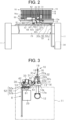
FIG. 3 is a side view illustrating the weft yarn tensioning device and the surroundings according to the embodiment; -
FIG. 4 is a figure illustrating a sub tank and an on-off valve that are adjusted in position; and -
FIG. 5 is a perspective view illustrating a weft yarn tensioning device and the surroundings according to another embodiment. - The following will describe an embodiment of a weft yarn tensioning device for an air jet loom with reference to
FIG. 1 to FIG. 4 . - As illustrated in
FIGS. 1 and2 , anair jet loom 10 includes a pair of left andright side frames 11 and arocking shaft 12 that is supported by theside frames 11 and rotatable in a reciprocating manner. A plurality ofarms 12a is provided on the rockingshaft 12 and extends upward from therocking shaft 12. Asley 13 is supported on upper ends of thearms 12a. Thesley 13 swings together with the rockingshaft 12 by the reciprocating motion of the rockingshaft 12. - The
sley 13 has a supportinggroove 14 into which a lower end of aprofile reed 16 is inserted. Theprofile reed 16 forms a weft yarn guide passage 16a. That is, theprofile reed 16 that forms the weft yarn guide passage 16a is provided in thesley 13. The lower end of theprofile reed 16 is fixed by awedge 17 inserted into the supportinggroove 14. Theprofile reed 16 is formed of a lot ofdents 18 arranged in a longitudinal direction of thesley 13. Upper ends of thedents 18 are held by anupper frame 19 of theprofile reed 16. - The
air jet loom 10 includes asub nozzle 20 disposed on a front surface side of theprofile reed 16. Thesub nozzle 20 is attached to agroove 13a formed in asley 13 and movable along thegroove 13a. A position of thesub nozzle 20 is adjustable in the longitudinal direction of thesley 13. - As illustrated in
FIGS. 1 and3 , theair jet loom 10 includes a weft yarn catching pipe 22. The weft yarn catching pipe 22 is disposed on a rear surface side of theprofile reed 16. The weft yarn catching pipe 22 is fixed at a predetermined position in the longitudinal direction of thesley 13. The weft yarn catching pipe 22 is bent to have an L-shape. Ashort portion 22a of the weft yarn catching pipe 22 is disposed substantially at right angles to theprofile reed 16. Aninlet 22b is open at an end portion of theshort portion 22a. Theinlet 22b communicates with the weft yarn guide passage 16a. - A
long portion 22c of the weft yarn catching pipe 22 is disposed substantially in parallel with theprofile reed 16. Anoutlet 22d is open at a rear end portion of thelong portion 22c and is oriented to a downstream side in a weft insertion direction. Here, the weft yarn insertion direction is a direction in which a weft yarn travels through the weft yarn guide passage 16a. Compressed air injected from an injection hole 31a of astretch nozzle 31, which will be described later, is blown into theinlet 22b across the weft yarn guide passage 16a. The compressed air flows from theshort portion 22a to thelong portion 22c in the weft yarn catching pipe 22 while turning the corner of the substantially right angles, and flows out from theoutlet 22d. - As illustrated in
FIGS. 1 and2 , theair jet loom 10 includes a supportingbar 23 formed between the pair ofside frames 11. Atemple device 60 for preventing crimp of woven fabric is provided on the supportingbar 23. Thetemple device 60 includes atemple base 61 and temple devicemain bodies 62 each provided on left and right sides of thetemple base 61. Thetemple base 61 is a plate having a trapezoidal shape when viewed in a cross-section and is supported on an upper surface of the supportingbar 23. Thetemple base 61 is supported by the supportingbar 23 with a longitudinal direction of thetemple base 61 coinciding with a longitudinal direction of the supportingbar 23. Note that although the temple devicemain bodies 62 are each provided in one end portion of thetemple base 61 on a weft insertion side from which the weft yarn is inserted into the weft yarn guide passage 16a and in the other end portion of thetemple base 61 on a counter-weft insertion side, which is a side opposite to the weft insertion side across thetemple base 61, an illustration of the temple devicemain body 62 on the weft insertion side is omitted. Here, thetemple base 61 extends in a left and right direction of theair jet room 10. The following will describe the temple devicemain body 62 provided on the end portion of thetemple base 61 on the counter-weft insertion side. - The temple device
main body 62 is movable in the longitudinal direction of thetemple base 61 such that its attachment position to thetemple base 61 is adjusted. The temple devicemain body 62 includes atemple bracket 63, a supportingbracket 65 integrated with thetemple bracket 63, and a temple main body supported by the supportingbracket 65. An illustration of the temple main body is omitted. The temple devicemain body 62 also includes anattachment piece 64 integrated with thetemple bracket 63. In the temple devicemain body 62, thetemple bracket 63, the supportingbracket 65, and the temple main body which is not illustrated are integrated with each other. - The
attachment piece 64 of the temple devicemain body 62 is disposed so as to face a side surface of thetemple base 61. The temple devicemain body 62 is positioned relative to thetemple base 61 by screwing abolt 67 inserted through theattachment piece 64 while thebolt 67 is pressed against thetemple base 61. In addition, when thebolt 67 is screwed out from theattachment piece 64, the temple devicemain body 62 is movable in the longitudinal direction of thetemple base 61. - A weft
yarn tensioning device 30 for the airjet loom 10 includes thestretch nozzle 31, an on-offvalve 32, asub tank 33, and amain tank 34. - The
main tank 34 is provided in theside frame 11 located on the counter-weft insertion side of the pair of side frames 11. Themain tank 34 stores compressed air at high pressure. Themain tank 34 is a supply source from which the compressed air is supplied to thestretch nozzle 31. - As illustrated in
FIG. 3 , thestretch nozzle 31 is attached to thegroove 13a formed in thesley 13. A position of thestretch nozzle 31 is adjustable along a longitudinal direction of thegroove 13a. That is, thestretch nozzle 31 is provided in thesley 13 such that thestretch nozzle 31 is movable in the weft insertion direction of a weft yarn. Thestretch nozzle 31 is provided such that the injection hole 31a of thestretch nozzle 31 faces theinlet 22b of the weft yarn catching pipe 22, and thestretch nozzle 31 is oriented toward the weft yarn guide passage 16a. - As illustrated in
FIGS. 1 ,2, and 3 , the on-offvalve 32 and thesub tank 33 are integrated with the temple devicemain body 62. Abracket 42 is fastened to thetemple bracket 63. Thebracket 42 has afirst attachment piece 42a attached to thetemple bracket 63, asecond attachment piece 42b attached to thesub tank 33, and a third attachment piece 42c to which the on-offvalve 32 is attached. Thebracket 42 is formed by bending a plate material so that thefirst attachment piece 42a, thesecond attachment piece 42b, and the third attachment piece 42c are formed. - In the
bracket 42 attached to thetemple bracket 63 by thefirst attachment piece 42a, thesecond attachment piece 42b is attached to thesub tank 33, and the on-offvalve 32 is attached to the third attachment piece 42c. Accordingly, the temple devicemain body 62, the on-offvalve 32, and thesub tank 33 are integrated by thebracket 42. When the temple devicemain body 62 is moved relative to thetemple base 61, the on-offvalve 32 and thesub tank 33 are also moved integrally with the temple devicemain body 62. In addition, when the temple devicemain body 62 is attached to thetemple base 61, the on-offvalve 32 and thesub tank 33 are also provided on thetemple base 61 through the temple devicemain body 62. Thus, the on-offvalve 32 and thesub tank 33 are provided on thetemple base 61. - The on-off
valve 32 is connected to thestretch nozzle 31 through afirst air tube 51. Thefirst air tube 51 is, for example, a flexible tube such as a resin hose. Thefirst air tube 51 with extra length connects thestretch nozzle 31 to the on-offvalve 32. - The
sub tank 33 is connected to the on-offvalve 32 through a first joint 55 and athird air tube 53. The first joint 55 is connected to thesub tank 33. Thethird air tube 53 is, for example, a flexible tube such as a resin hose. Thethird air tube 53 with extra length connects the on-offvalve 32 to thesub tank 33. - The
main tank 34 is provided in theside frame 11 on a side where the on-offvalve 32 is attached to the temple devicemain body 62, that is, in theside frame 11 on the counter-weft insertion side, of the pair of side frames 11. Thestretch nozzle 31 is provided near the on-offvalve 32, and thus, themain tank 34 is provided in theside frame 11 close to thestretch nozzle 31 of the pair of side frames 11. Themain tank 34 is connected to thesub tank 33 through the first joint 55 and asecond air tube 52. Thesecond air tube 52 includes a subtank side tube 52a, a second joint 56, and a maintank side tube 52b. A first end of the subtank side tube 52a is connected to the first joint 55, and a second end of the subtank side tube 52a is connected to the second joint 56. A first end of the maintank side tube 52b is connected to the second joint 56, and a second end of the maintank side tube 52b is connected to themain tank 34. - The sub
tank side tube 52a is a flexible tube. The subtank side tube 52a with extra length connects the first joint 55 to the second joint 56. - The main
tank side tube 52b is made of a steel tube, and a diameter of the maintank side tube 52b is larger than that of the subtank side tube 52a. The maintank side tube 52b extends straight downward from the second joint 56, and is bent toward themain tank 34 near the second end of the maintank side tube 52b. The maintank side tube 52b is integrated with theside frame 11, and keeps a shape extending straight by itself due to stiffness of the maintank side tube 52b. The second joint 56 connected to the first end of the maintank side tube 52b is positioned at a predetermined position due to the stiffness of the maintank side tube 52b. - That is, the second joint 56 is located above the upper surface of the supporting
bar 23 and near thetemple base 61. Accordingly, this subtank side tube 52a connecting the second joint 56 to the first joint 55 is disposed above the upper surface of the supportingbar 23. An extra length portion of the subtank side tube 52a is also disposed above the upper surface of the supportingbar 23. The extra length portion of the subtank side tube 52a is made short or long between the first joint 55 and the second joint 56 above the upper surface of the supportingbar 23. That is, the subtank side tube 52a is a flexible tube disposed above the upper surface of the supportingbar 23. - A length of the sub
tank side tube 52a between the first joint 55 and the second joint 56 is set depending on a movable range of the temple devicemain body 62. The length of the subtank side tube 52a is set such that the subtank side tube 52a does not get strained and has some extra length even when the temple devicemain body 62 is moved to a position farthest from theside frame 11 in which themain tank 34 is provided. - The compressed air at high pressure stored in the
main tank 34 is supplied to thesub tank 33 through the maintank side tube 52b, the second joint 56, the subtank side tube 52a, and the first joint 55. Pressure loss between themain tank 34 and thesub tank 33 is reduced due to the maintank side tube 52b with the large diameter as compared with a configuration in which the maintank side tube 52b and the subtank side tube 52a have the same diameter. - As described above, a flow passage R is formed of the
third air tube 53, the first joint 55, thesub tank 33, and thesecond air tube 52 between the on-offvalve 32 and themain tank 34. Thesub tank 33 smaller than themain tank 34 is disposed on this flow passage R. The size of thesub tank 33 is set such that one air injection from thestretch nozzle 31 does not cause a pressure drop of a predetermined value or more. - In the above-described weft
yarn tensioning device 30, when the on-offvalve 32 opens, the compressed air stored in thesub tank 33 is supplied to thestretch nozzle 31 through thefirst air tube 51. On the other hand, when the on-offvalve 32 closes, the air flow to thefirst air tube 51 is shut off, so that the supply of the compressed air from thesub tank 33 to thestretch nozzle 31 is stopped and the compressed air is supplied from themain tank 34 to thesub tank 33 through the maintank side tube 52b and the subtank side tube 52a until the next air injection. Accordingly, the compressed air is supplied from themain tank 34 to thesub tank 33 while the on-offvalve 32 is closed, so that thesub tank 33 stores the compressed air at high pressure before the on-offvalve 32 opens, similarly to themain tank 34. - During operation of the air jet loom 10, a weft yarn is inserted into the weft yarn guide passage 16a by a weft yarn insertion nozzle and the
sub nozzle 20. Illustrations of the weft yarn and the weft yarn insertion nozzle are omitted. When the inserted weft yarn reaches the front of the injection hole 31a of thestretch nozzle 31, the on-offvalve 32 opens. The compressed air in thesub tank 33 is supplied to thestretch nozzle 31 through thethird air tube 53, the on-offvalve 32, and thefirst air tube 51. Then, the compressed air is injected from the injection hole 31a of thestretch nozzle 31 in a direction perpendicular to the weft yarn guide passage 16a. - The weft yarn in the weft yarn guide passage 16a is blown to the
inlet 22b of the weft yarn catching pipe 22 by the compressed air. The compressed air is guided from theshort portion 22a to thelong portion 22c in the weft yarn catching pipe 22. Accordingly, after the weft yarn is bent at the right angles while being blown from the weft yarn guide passage 16a to theshort portion 22a of the weft yarn catching pipe 22, the weft yarn is maintained in a bent state at the right angles while being blown from theshort portion 22a to thelong portion 22c in the weft yarn catching pipe 22 again. When the weft yarn is beaten in this state, the inserted weft yarn is woven into woven fabric while being applied to a predetermined tension over an entire length of the weft yarn because the weft yarn is held by theprofile reed 16, thestretch nozzle 31, and the weft yarn catching pipe 22. - As illustrated in
FIG. 4 , in order to weave woven fabric with a certain width, the position of thestretch nozzle 31 is adjusted along the longitudinal direction of thegroove 13a formed in thesley 13. In addition, the position of the temple devicemain body 62 is also adjusted in accordance with the width of the woven fabric. In the positional adjustment of the temple devicemain body 62, thebolt 67 is screwed out from theattachment piece 64 to make the temple devicemain body 62 movable along thetemple base 61. Then, the position of the temple devicemain body 62 is adjusted such that the temple main body, which is not illustrated, is located at a position in accordance with the width of the woven fabric. The on-offvalve 32 and thesub tank 33 are integrated with this temple devicemain body 62, so that the on-offvalve 32 and thesub tank 33 are also moved integrally with the temple devicemain body 62 as the temple devicemain body 62 moves. - In the temple device
main body 62 adjusted at a desired position, thebolt 67 is inserted into theattachment piece 64 and screwed while pressed against thetemple base 61. This positions the temple devicemain body 62, and by extension, the on-offvalve 32 and thesub tank 33. As a result, the on-offvalve 32 and thesub tank 33 are provided on the end portion of thetemple base 61 on the counter-weft insertion side. - In accordance with the positional adjustment of the
stretch nozzle 31, positions of the on-offvalve 32 and thesub tank 33 are also adjusted. Here, the on-offvalve 32 is moved integrally with thesub tank 33, and thus, thethird air tube 53 connecting the on-offvalve 32 to thesub tank 33 is hardly stretched or slackened. On the other hand, a distance between thesub tank 33 and themain tank 34 varies. For example, when thesub tank 33 leaves themain tank 34, the subtank side tube 52a with the extra length portion is stretched such that the extra length portion is shortened. This stretch of the subtank side tube 52a allows the movement of thesub tank 33. On the other hand, the maintank side tube 52b does not stretch. - On the contrary, as compared with a case in
FIG. 4 , when thesub tank 33 approaches themain tank 34 as illustrated inFIG. 2 , thestretch nozzle 31 is moved toward theside frame 11 in which themain tank 34 is provided to adjust its position. In addition, the position of the temple devicemain body 62 is also adjusted in accordance with the width of the woven fabric. Here, the temple devicemain body 62 is moved by the same method described above, and the on-offvalve 32 and thesub tank 33 are also moved integrally with the temple devicemain body 62. - Here, the on-off
valve 32 is moved integrally with thesub tank 33, and thus, thethird air tube 53 connecting the on-offvalve 32 to thesub tank 33 is hardly stretched or slackened. On the other hand, thesub tank 33 moves so as to approach themain tank 34. Here, the first end of the stretched subtank side tube 52a with the shortened extra length portion is displaced such that the extra length portion becomes long. This displacement of the subtank side tube 52a allows the movement of thesub tank 33. On the other hand, the maintank side tube 52b is not stretched. - The following effects are obtained by the above-described embodiment.
- (1) The compressed air is supplied from the
main tank 34 to thesub tank 33 while the on-offvalve 32 is closed, so that thesub tank 33 stores the compressed air at high pressure before the on-offvalve 32 opens, similarly to themain tank 34. Thesub tank 33 is provided on thetemple base 61, and thus, thesub tank 33 is closer to the on-offvalve 32 than themain tank 34. With this configuration, pressure loss between thesub tank 33 and the on-offvalve 32 is reduced, which suppresses the decrease of the injection pressure from thestretch nozzle 31. As a result, in thesecond air tube 52 between the on-offvalve 32 and themain tank 34, the subtank side tube 52a connected to thesub tank 33 may be formed of a flexible tube with a smaller diameter than that of the maintank side tube 52b. This suppresses that the stiffness of thesecond air tube 52 interferes with the positional adjustment of the on-offvalve 32 when the on-offvalve 32 is moved in accordance with the positional adjustment of thestretch nozzle 31. Thus, the on-offvalve 32 is easily moved. - (2) The on-off
valve 32 is integrated with thesub tank 33 by thebracket 42. With this configuration, the on-offvalve 32 and thesub tank 33 are disposed closer to each other by shortening the distance between the on-offvalve 32 and thesub tank 33. Thus, the decrease of the injection pressure from thestretch nozzle 31 is further suppressed by shortening the distance between thesub tank 33 and the on-offvalve 32. - (3) The on-off
valve 32 and thesub tank 33 are integrated with each other by thebracket 42, and thus, thesub tank 33 is also moved as the on-offvalve 32 moves. Here, the distance between the on-offvalve 32 and thesub tank 33 is constant, so that the distance between the on-offvalve 32 and thesub tank 33 does not become longer even when the on-offvalve 32 and thesub tank 33 are moved. Accordingly, the pressure loss between the on-offvalve 32 and thesub tank 33 does not increase by the movement of the on-offvalve 32 and thesub tank 33. - (4) The
sub tank 33 is connected to themain tank 34 by the first joint 55 and thesecond air tube 52. The maintank side tube 52b in thesecond air tube 52 is the tube with the large diameter, and the subtank side tube 52a is a flexible tube with the smaller diameter than that of the maintank side tube 52b. With this configuration, in the weftyarn tensioning device 30, the pressure loss between themain tank 34 and thesub tank 33 is reduced due to the maintank side tube 52b with the large diameter. In addition, in the weftyarn tensioning device 30, the on-offvalve 32 is easily moved due to the flexible subtank side tube 52a with the small diameter. Resistance against deformation of the subtank side tube 52a when thesub tank 33 is moved is suppressed by using the flexible subtank side tube 52a with the small diameter, so that thesub tank 33 is easily moved. - The present embodiment may be modified as follows. The present embodiment and the following modification may be combined with each other as long as they do not technically contradict each other.
- As illustrated in
FIG. 5 , atemple base 71 may be supported above the supportingbar 23. A temple device main body, which is not illustrated, is supported on thetemple base 71 supported above the supportingbar 23. - In this case, the on-off
valve 32 is attached to afirst bracket 451, and thesub tank 33 is attached to asecond bracket 452. Then, thefirst bracket 451 and thesecond bracket 452 are attached to a supportingmember 453, and the supportingmember 453 is attached to thetemple base 71. Thus, the on-offvalve 32 and thesub tank 33 are separately provided on thetemple base 71. - The supporting
member 453 is attached to thetemple base 71 such that a position of the supportingmember 453 is adjustable in a longitudinal direction of thetemple base 71. Furthermore, positions of thefirst bracket 451 and thesecond bracket 452 are adjustable in the longitudinal direction of thetemple base 71 with respect to the supportingmember 453. - It is sometimes preferable to adjust the positions of the on-off
valve 32 and thesub tank 33 separately in accordance with the width of the woven fabric. Even in such a case, the on-offvalve 32 and thesub tank 33 are separately moved to be adjusted in position by adjusting the positions of thefirst bracket 451 and thesecond bracket 452 with respect to the supportingmember 453. - In this case, the
third air tube 53 connecting the on-offvalve 32 to thesub tank 33 preferably has an extra length portion in order to adjust the positions of the on-offvalve 32 and thesub tank 33 such that the distance between on-offvalve 32 and thesub tank 33 becomes longer. - The main
tank side tube 52b is not limited to the tube with the large diameter described in the embodiment, and may be a flexible tube or a tube with a small diameter, such as the subtank side tube 52a. Even with this configuration, due to thesub tank 33 disposed near thestretch nozzle 31 and the on-offvalve 32, the decrease of the injection pressure from thestretch nozzle 31 is suppressed. In addition, the on-offvalve 32 is easily moved due to the subtank side tube 52a. - The second joint 56 may be fixed to the
side frame 11 or the supportingbar 23. - The second joint 56 may be omitted. In this case, the
second air tube 52 connecting thesub tank 33 to themain tank 34 is formed of one air tube. - The second joint 56 may be located below the upper surface of the supporting
bar 23. In this case, the subtank side tube 52a is disposed on the upper surface of the supportingbar 23, and extends also below the supportingbar 23. - The
sub tank 33 may be attached to thetemple base 61. In this case, only the on-offvalve 32 is integrated with the temple devicemain body 62 and moved in accordance with the positional adjustment of thestretch nozzle 31. - The on-off
valve 32 and thesub tank 33 need not be integrated with the temple devicemain body 62. For example, the on-offvalve 32 and thesub tank 33 may be separately movable along the upper surface of thetemple base 61 and be provided on thetemple base 61. In short, as long as the positions of the on-offvalve 32 and thesub tank 33 are adjustable in accordance with the positional adjustment of thestretch nozzle 31, the on-offvalve 32 and thesub tank 33 may be provided in any suitable manner. - In the embodiment, the
first air tube 51 connecting the on-offvalve 32 to thestretch nozzle 31 may be a steel tube with high stiffness instead of the flexible tube. - The on-off
valve 32 and thesub tank 33 are integrated with the temple devicemain body 62 by thebracket 42. However, the on-offvalve 32 and thesub tank 33 may be separately integrated with the temple devicemain body 62. - The on-off
valve 32 and thesub tank 33 need not be integrated with the temple devicemain body 62. - The on-off
valve 32 and thesub tank 33 may be directly connected without thethird air tube 53. - The following will describe a technical idea to be obtained from the above-described embodiment and modifications.
- (I) The main tank side tube is made of a steel tube.
Claims (4)
- A weft yarn tensioning device (30) for an air jet loom (10) including a pair of side frames (11), a rocking shaft (12) that is supported by the side frames (11) and rotatable in a reciprocating manner, a sley (13) that swings together with the rocking shaft (12), and a profile reed (16) that is provided in the sley (13) and forms a weft yarn guide passage (16a),
the weft yarn tensioning device (30) comprising:a stretch nozzle (31) oriented toward the weft yarn insertion passage (16a), the stretch nozzle (31) being provided in the sley (13) such that the stretch nozzle (31) is movable in a weft insertion direction of a weft yarn;a main tank (34) as a supply source of compressed air, the main tank (34) being provided in the side frame (11) close to the stretch nozzle (31) of the pair of side frames (11); andan on-off valve (32) connected to the stretch nozzle (31) through a first air tube (51), characterized in thatthe on-off valve (32) is provided on an end portion of a temple base (61, 71) on a counter-weft insertion side, the temple base (61, 71) being supported by a supporting bar (23) formed between the pair of side frames (11), anda sub tank (33) is provided on the end portion of the temple base (61, 71) on the counter-weft insertion side, the sub tank (33) being smaller than the main tank (34), connected to the on-off valve (32), and connected to the main tank (34) through a second air tube (52). - The weft yarn tensioning device (30) for the air jet loom (10) according to claim 1, characterized in that
the on-off valve (32) and the sub tank (33) are integrated with each other. - The weft yarn tensioning device (30) for the air jet loom (10) according to claim 1, characterized in that
the on-off valve (32) and the sub tank (33) are separately provided on the temple base (61, 71). - The weft yarn tensioning device (30) for the air jet loom (10) according to any one of claims 1 to 3, characterized in thatthe second air tube (52) is formed of a sub tank side tube (52a) connected to the sub tank (33), a main tank side tube (52b) connected to the main tank (34), and a joint (56) connecting the sub tank side tube (52a) to the main tank side tube (34),the main tank side tube (52b) has a diameter larger than a diameter of the sub tank side tube (52a), andthe sub tank side tube (52a) is a flexible tube.
Applications Claiming Priority (1)
| Application Number | Priority Date | Filing Date | Title |
|---|---|---|---|
| JP2023084597A JP2024168158A (en) | 2023-05-23 | 2023-05-23 | Weft tensioning device for air jet loom |
Publications (2)
| Publication Number | Publication Date |
|---|---|
| EP4467696A1 true EP4467696A1 (en) | 2024-11-27 |
| EP4467696B1 EP4467696B1 (en) | 2026-04-22 |
Family
ID=89940842
Family Applications (1)
| Application Number | Title | Priority Date | Filing Date |
|---|---|---|---|
| EP24157520.8A Active EP4467696B1 (en) | 2023-05-23 | 2024-02-14 | Air jet loom with weft yarn tensioning device |
Country Status (3)
| Country | Link |
|---|---|
| EP (1) | EP4467696B1 (en) |
| JP (1) | JP2024168158A (en) |
| CN (1) | CN119020907A (en) |
Citations (3)
| Publication number | Priority date | Publication date | Assignee | Title |
|---|---|---|---|---|
| JPH0633982U (en) * | 1992-10-05 | 1994-05-06 | 日産自動車株式会社 | Weft insertion control device for fluid jet loom |
| EP2163670B1 (en) * | 2008-09-12 | 2014-11-05 | Picanol | Method for controlling transportation of a weft thread through a shed |
| EP2808431A1 (en) * | 2013-05-29 | 2014-12-03 | Kabushiki Kaisha Toyota Jidoshokki | Weft yarn tension applying apparatus in air jet loom |
Family Cites Families (2)
| Publication number | Priority date | Publication date | Assignee | Title |
|---|---|---|---|---|
| JPH1112891A (en) * | 1997-06-17 | 1999-01-19 | Toyota Autom Loom Works Ltd | Pressure setting apparatus for air-jet loom |
| CN111577582B (en) * | 2020-04-28 | 2021-10-26 | 中国科学院工程热物理研究所 | Compressed air auxiliary power system |
-
2023
- 2023-05-23 JP JP2023084597A patent/JP2024168158A/en active Pending
-
2024
- 2024-02-14 EP EP24157520.8A patent/EP4467696B1/en active Active
- 2024-03-28 CN CN202410365319.8A patent/CN119020907A/en active Pending
Patent Citations (4)
| Publication number | Priority date | Publication date | Assignee | Title |
|---|---|---|---|---|
| JPH0633982U (en) * | 1992-10-05 | 1994-05-06 | 日産自動車株式会社 | Weft insertion control device for fluid jet loom |
| EP2163670B1 (en) * | 2008-09-12 | 2014-11-05 | Picanol | Method for controlling transportation of a weft thread through a shed |
| EP2808431A1 (en) * | 2013-05-29 | 2014-12-03 | Kabushiki Kaisha Toyota Jidoshokki | Weft yarn tension applying apparatus in air jet loom |
| JP2014231649A (en) | 2013-05-29 | 2014-12-11 | 株式会社豊田自動織機 | Weft tension applying device in air jet loom |
Also Published As
| Publication number | Publication date |
|---|---|
| JP2024168158A (en) | 2024-12-05 |
| CN119020907A (en) | 2024-11-26 |
| EP4467696B1 (en) | 2026-04-22 |
Similar Documents
| Publication | Publication Date | Title |
|---|---|---|
| CN101460669A (en) | Method for clamping a weft thread in a jet weaving machine, in particular air-jet weaving machine, clamping device and jet weaving machine | |
| JP7303059B2 (en) | Weft insertion device in water jet loom | |
| CN102094283B (en) | Weaving edge forming device of rubber strengthening textile weaving loom | |
| US4476903A (en) | Shuttleless weaving machine | |
| US20070023098A1 (en) | Holding element for a device for monitoring the quality on a mechanical weaving loom | |
| EP4467696B1 (en) | Air jet loom with weft yarn tensioning device | |
| EP2476788A2 (en) | Weaving method for air jet loom | |
| JP5884774B2 (en) | Weft tension applying device for air jet loom | |
| JP2016084557A (en) | Weft tension applying device for air jet loom | |
| JPH01280046A (en) | Air jet loom | |
| JP2008063715A (en) | Process and stretching device for holding weft thread | |
| CN100554544C (en) | Pneumatic Yarn Tensioners and Yarn Handling Systems | |
| EP2610378B1 (en) | Auxiliary nozzle of air jet loom | |
| EP3936649B1 (en) | Weft yarn tensioning device | |
| CN101023208B (en) | Jet-weaving machine, particularly an air jet-weaving machine, with a clamping device in the mixing tube | |
| CN219991846U (en) | Weft insertion device of air-jet loom | |
| KR100467014B1 (en) | Device for stretching and tensing a weft yarn | |
| CN102094282B (en) | Weft insertion device for air-jet loom | |
| EP4575056A1 (en) | Air jet loom | |
| JP2000355855A (en) | Restriction of shed opening and restriction device therefor | |
| US20030201026A1 (en) | Catching and holding apparatus for the catching-side weft thread end in a weaving machine | |
| KR102107781B1 (en) | flat yarn feed supply | |
| JP4028349B2 (en) | Weft gripping device for fluid jet loom | |
| JPH1136161A (en) | Warp tension controller in loom | |
| EP0458754A1 (en) | Device for tensioning warp yarns in a weaving loom |
Legal Events
| Date | Code | Title | Description |
|---|---|---|---|
| PUAI | Public reference made under article 153(3) epc to a published international application that has entered the european phase |
Free format text: ORIGINAL CODE: 0009012 |
|
| STAA | Information on the status of an ep patent application or granted ep patent |
Free format text: STATUS: REQUEST FOR EXAMINATION WAS MADE |
|
| 17P | Request for examination filed |
Effective date: 20240214 |
|
| AK | Designated contracting states |
Kind code of ref document: A1 Designated state(s): AL AT BE BG CH CY CZ DE DK EE ES FI FR GB GR HR HU IE IS IT LI LT LU LV MC ME MK MT NL NO PL PT RO RS SE SI SK SM TR |
|
| RIC1 | Information provided on ipc code assigned before grant |
Ipc: D03D 47/30 20060101AFI20251002BHEP |
|
| GRAP | Despatch of communication of intention to grant a patent |
Free format text: ORIGINAL CODE: EPIDOSNIGR1 |
|
| STAA | Information on the status of an ep patent application or granted ep patent |
Free format text: STATUS: GRANT OF PATENT IS INTENDED |
|
| INTG | Intention to grant announced |
Effective date: 20251124 |
|
| GRAS | Grant fee paid |
Free format text: ORIGINAL CODE: EPIDOSNIGR3 |
|
| GRAA | (expected) grant |
Free format text: ORIGINAL CODE: 0009210 |
|
| STAA | Information on the status of an ep patent application or granted ep patent |
Free format text: STATUS: THE PATENT HAS BEEN GRANTED |
|
| AK | Designated contracting states |
Kind code of ref document: B1 Designated state(s): AL AT BE BG CH CY CZ DE DK EE ES FI FR GB GR HR HU IE IS IT LI LT LU LV MC ME MK MT NL NO PL PT RO RS SE SI SK SM TR |
|
| REG | Reference to a national code |
Ref country code: CH Ref legal event code: F10 Free format text: ST27 STATUS EVENT CODE: U-0-0-F10-F00 (AS PROVIDED BY THE NATIONAL OFFICE) Effective date: 20260422 Ref country code: GB Ref legal event code: FG4D |
|
| REG | Reference to a national code |
Ref country code: DE Ref legal event code: R096 Ref document number: 602024004061 Country of ref document: DE |