EP4467688A1 - Surface treatment jig - Google Patents
Surface treatment jig Download PDFInfo
- Publication number
- EP4467688A1 EP4467688A1 EP23774970.0A EP23774970A EP4467688A1 EP 4467688 A1 EP4467688 A1 EP 4467688A1 EP 23774970 A EP23774970 A EP 23774970A EP 4467688 A1 EP4467688 A1 EP 4467688A1
- Authority
- EP
- European Patent Office
- Prior art keywords
- surface treatment
- treatment jig
- exterior body
- support
- port
- Prior art date
- Legal status (The legal status is an assumption and is not a legal conclusion. Google has not performed a legal analysis and makes no representation as to the accuracy of the status listed.)
- Pending
Links
Images




Classifications
-
- C—CHEMISTRY; METALLURGY
- C25—ELECTROLYTIC OR ELECTROPHORETIC PROCESSES; APPARATUS THEREFOR
- C25D—PROCESSES FOR THE ELECTROLYTIC OR ELECTROPHORETIC PRODUCTION OF COATINGS; ELECTROFORMING; APPARATUS THEREFOR
- C25D7/00—Electroplating characterised by the article coated
- C25D7/04—Tubes; Rings; Hollow bodies
-
- B—PERFORMING OPERATIONS; TRANSPORTING
- B05—SPRAYING OR ATOMISING IN GENERAL; APPLYING FLUENT MATERIALS TO SURFACES, IN GENERAL
- B05B—SPRAYING APPARATUS; ATOMISING APPARATUS; NOZZLES
- B05B13/00—Machines or plants for applying liquids or other fluent materials to surfaces of objects or other work by spraying, not covered by groups B05B1/00 - B05B11/00
- B05B13/02—Means for supporting work; Arrangement or mounting of spray heads; Adaptation or arrangement of means for feeding work
-
- C—CHEMISTRY; METALLURGY
- C25—ELECTROLYTIC OR ELECTROPHORETIC PROCESSES; APPARATUS THEREFOR
- C25D—PROCESSES FOR THE ELECTROLYTIC OR ELECTROPHORETIC PRODUCTION OF COATINGS; ELECTROFORMING; APPARATUS THEREFOR
- C25D17/00—Constructional parts, or assemblies thereof, of cells for electrolytic coating
- C25D17/06—Suspending or supporting devices for articles to be coated
-
- C—CHEMISTRY; METALLURGY
- C25—ELECTROLYTIC OR ELECTROPHORETIC PROCESSES; APPARATUS THEREFOR
- C25D—PROCESSES FOR THE ELECTROLYTIC OR ELECTROPHORETIC PRODUCTION OF COATINGS; ELECTROFORMING; APPARATUS THEREFOR
- C25D7/00—Electroplating characterised by the article coated
-
- F—MECHANICAL ENGINEERING; LIGHTING; HEATING; WEAPONS; BLASTING
- F15—FLUID-PRESSURE ACTUATORS; HYDRAULICS OR PNEUMATICS IN GENERAL
- F15B—SYSTEMS ACTING BY MEANS OF FLUIDS IN GENERAL; FLUID-PRESSURE ACTUATORS, e.g. SERVOMOTORS; DETAILS OF FLUID-PRESSURE SYSTEMS, NOT OTHERWISE PROVIDED FOR
- F15B1/00—Installations or systems with accumulators; Supply reservoir or sump assemblies
- F15B1/02—Installations or systems with accumulators
- F15B1/04—Accumulators
- F15B1/08—Accumulators using a gas cushion; Gas charging devices; Indicators or floats therefor
- F15B1/10—Accumulators using a gas cushion; Gas charging devices; Indicators or floats therefor with flexible separating means
- F15B1/103—Accumulators using a gas cushion; Gas charging devices; Indicators or floats therefor with flexible separating means the separating means being bellows
-
- F—MECHANICAL ENGINEERING; LIGHTING; HEATING; WEAPONS; BLASTING
- F15—FLUID-PRESSURE ACTUATORS; HYDRAULICS OR PNEUMATICS IN GENERAL
- F15B—SYSTEMS ACTING BY MEANS OF FLUIDS IN GENERAL; FLUID-PRESSURE ACTUATORS, e.g. SERVOMOTORS; DETAILS OF FLUID-PRESSURE SYSTEMS, NOT OTHERWISE PROVIDED FOR
- F15B1/00—Installations or systems with accumulators; Supply reservoir or sump assemblies
- F15B1/02—Installations or systems with accumulators
- F15B1/04—Accumulators
- F15B1/08—Accumulators using a gas cushion; Gas charging devices; Indicators or floats therefor
- F15B1/10—Accumulators using a gas cushion; Gas charging devices; Indicators or floats therefor with flexible separating means
- F15B1/106—Accumulators using a gas cushion; Gas charging devices; Indicators or floats therefor with flexible separating means characterised by the way housing components are assembled
-
- F—MECHANICAL ENGINEERING; LIGHTING; HEATING; WEAPONS; BLASTING
- F15—FLUID-PRESSURE ACTUATORS; HYDRAULICS OR PNEUMATICS IN GENERAL
- F15B—SYSTEMS ACTING BY MEANS OF FLUIDS IN GENERAL; FLUID-PRESSURE ACTUATORS, e.g. SERVOMOTORS; DETAILS OF FLUID-PRESSURE SYSTEMS, NOT OTHERWISE PROVIDED FOR
- F15B2201/00—Accumulators
- F15B2201/20—Accumulator cushioning means
- F15B2201/205—Accumulator cushioning means using gas
-
- F—MECHANICAL ENGINEERING; LIGHTING; HEATING; WEAPONS; BLASTING
- F15—FLUID-PRESSURE ACTUATORS; HYDRAULICS OR PNEUMATICS IN GENERAL
- F15B—SYSTEMS ACTING BY MEANS OF FLUIDS IN GENERAL; FLUID-PRESSURE ACTUATORS, e.g. SERVOMOTORS; DETAILS OF FLUID-PRESSURE SYSTEMS, NOT OTHERWISE PROVIDED FOR
- F15B2201/00—Accumulators
- F15B2201/30—Accumulator separating means
- F15B2201/315—Accumulator separating means having flexible separating means
- F15B2201/3153—Accumulator separating means having flexible separating means the flexible separating means being bellows
-
- F—MECHANICAL ENGINEERING; LIGHTING; HEATING; WEAPONS; BLASTING
- F15—FLUID-PRESSURE ACTUATORS; HYDRAULICS OR PNEUMATICS IN GENERAL
- F15B—SYSTEMS ACTING BY MEANS OF FLUIDS IN GENERAL; FLUID-PRESSURE ACTUATORS, e.g. SERVOMOTORS; DETAILS OF FLUID-PRESSURE SYSTEMS, NOT OTHERWISE PROVIDED FOR
- F15B2201/00—Accumulators
- F15B2201/40—Constructional details of accumulators not otherwise provided for
- F15B2201/415—Gas ports
-
- F—MECHANICAL ENGINEERING; LIGHTING; HEATING; WEAPONS; BLASTING
- F15—FLUID-PRESSURE ACTUATORS; HYDRAULICS OR PNEUMATICS IN GENERAL
- F15B—SYSTEMS ACTING BY MEANS OF FLUIDS IN GENERAL; FLUID-PRESSURE ACTUATORS, e.g. SERVOMOTORS; DETAILS OF FLUID-PRESSURE SYSTEMS, NOT OTHERWISE PROVIDED FOR
- F15B2201/00—Accumulators
- F15B2201/60—Assembling or methods for making accumulators
- F15B2201/605—Assembling or methods for making housings therefor
-
- Y—GENERAL TAGGING OF NEW TECHNOLOGICAL DEVELOPMENTS; GENERAL TAGGING OF CROSS-SECTIONAL TECHNOLOGIES SPANNING OVER SEVERAL SECTIONS OF THE IPC; TECHNICAL SUBJECTS COVERED BY FORMER USPC CROSS-REFERENCE ART COLLECTIONS [XRACs] AND DIGESTS
- Y02—TECHNOLOGIES OR APPLICATIONS FOR MITIGATION OR ADAPTATION AGAINST CLIMATE CHANGE
- Y02E—REDUCTION OF GREENHOUSE GAS [GHG] EMISSIONS, RELATED TO ENERGY GENERATION, TRANSMISSION OR DISTRIBUTION
- Y02E60/00—Enabling technologies; Technologies with a potential or indirect contribution to GHG emissions mitigation
- Y02E60/10—Energy storage using batteries
Definitions
- the present invention relates to surface treatment jigs for performing, for example, surface treatment of accumulators.
- Bellows have been used conventionally as fluid separation membranes or fluid sealing membranes having airtightness and stretchability in accumulators.
- a bellows is provided in an internal space formed by an exterior body composed of a bottom, a shell, and a port.
- the exterior body is subjected to surface treatment so as to be increased in corrosion resistance.
- the port is attached to a jig, the jig is hung, paint is sprayed, and a metallic coating is thereby formed on a surface of the exterior body.
- a jig known as a jig used in coating has, for example, a columnar support portion that supports an object to be treated (for example, see Patent Literature 1 or Patent Literature 2).
- the coating thickness of the coating on a portion of the exterior body may become smaller than that of the coating on the rest of the exterior body, the portion being where the jig is connected to the exterior body.
- the present invention has been made in view of the above and an object thereof is to provide a surface treatment jig that enables minimization of reduction in coating thickness.
- a surface treatment jig is for performing surface treatment of an exterior body of an accumulator including a bottom, a shell and a port in a state where the surface treatment jig is connected to the exterior body and supports the exterior body, and includes: a support portion configured to support the accumulator; and a hook portion connected with the support portion, wherein the support portion has a shape tapered near the hook portion.
- the support portion includes: a head portion provided on a side near the hook portion; a bottom portion provided on an opposite side of the side near the head portion; and an intermediate portion provided between the head portion and the bottom portion, and the bottom portion has a height smaller than a sum of heights of the head portion and the intermediate portion.
- the support portion includes: a head portion provided on a side near the hook portion; and a bottom portion provided on an opposite side of the side near the head portion; and the bottom portion has a height smaller than a height of the head portion.
- FIG. 1 is a sectional diagram illustrating a configuration of an accumulator according to an embodiment of the present invention.
- An accumulator 1 illustrated in FIG. 1 includes: a bottom 11; a shell 12; a port 13; a bellows 14 housed in an internal space formed by the bottom 11, the shell 12, and the port 13; a cap body portion 15; a cap elastic portion 16; and a guide bellows 17.
- the bottom 11, the shell 12, and the port 13 compose an exterior body of the accumulator 1.
- the intermediate portion 113A has a hollow truncated cone shape, one end connected with the bottom portion 111A, and the other end connected with the head portion 112.
- the head portion 112 has the outer circumference having the diameter D 112 smaller than a diameter D 111A of the bottom portion 111A.
- the bottom portion 111A has a height H 111A smaller than the sum (H 112 + H 113A ) of the height H 112 of the head portion 112 and a height H 113A of the intermediate portion 113A.
- the height H 111A is also larger than the height H 111 of the bottom portion 111.
- FIG. 15 is a diagram for illustration of a configuration of a surface treatment jig according to the second modified example.
- the same reference sign is assigned to any portion that is the same as that of the surface treatment jig 100 according to the embodiment.
- a surface treatment jig 100B has a support portion 110B to support the port 13, and a hook portion 120 that is provided on an opposite side of the support portion 110B and that is ring-shaped, the opposite side being opposite to a side where the port 13 is connected.
- the surface treatment jig 100B has a shape tapered from the bottom portion 111 to the head portion 112A and the height of the bottom portion 111 has been set to the height H 111 that minimizes the electric current difference, cations are bonded to anions on the surface of the exterior body connected with the support portion 110B of the surface treatment jig 100B.
- the surface treatment jig 100B is configured to include the support portion 110B to support the port 13, the support portion 110B having the shape tapered toward the hook portion 120, the electric current difference at the surface of the exterior body is minimized and the formation of the coating on the surface of the exterior body is ensured.
- This second modified example enables minimization of reduction in coating thickness of an exterior body in surface treatment using a jig.
Landscapes
- Chemical & Material Sciences (AREA)
- Engineering & Computer Science (AREA)
- Chemical Kinetics & Catalysis (AREA)
- Electrochemistry (AREA)
- Materials Engineering (AREA)
- Metallurgy (AREA)
- Organic Chemistry (AREA)
- Physics & Mathematics (AREA)
- Fluid Mechanics (AREA)
- Mechanical Engineering (AREA)
- General Engineering & Computer Science (AREA)
- Electroplating Methods And Accessories (AREA)
- Physical Vapour Deposition (AREA)
Abstract
Description
- The present invention relates to surface treatment jigs for performing, for example, surface treatment of accumulators.
- Bellows have been used conventionally as fluid separation membranes or fluid sealing membranes having airtightness and stretchability in accumulators. A bellows is provided in an internal space formed by an exterior body composed of a bottom, a shell, and a port. The exterior body is subjected to surface treatment so as to be increased in corrosion resistance. For example, in the surface treatment, the port is attached to a jig, the jig is hung, paint is sprayed, and a metallic coating is thereby formed on a surface of the exterior body. A jig known as a jig used in coating has, for example, a columnar support portion that supports an object to be treated (for example, see
Patent Literature 1 or Patent Literature 2). -
- Patent Literature 1:
Japanese Unexamined Patent Application Publication No. 2013-136023 - Patent Literature 2:
Japanese Unexamined Patent Application Publication No. 57-165065 - However, in a case where the jig described in
Patent Literature 1 or 2 is used, the coating thickness of the coating on a portion of the exterior body may become smaller than that of the coating on the rest of the exterior body, the portion being where the jig is connected to the exterior body. - The present invention has been made in view of the above and an object thereof is to provide a surface treatment jig that enables minimization of reduction in coating thickness.
- To solve the above-described problem and achieve the object, a surface treatment jig according to the present invention is for performing surface treatment of an exterior body of an accumulator including a bottom, a shell and a port in a state where the surface treatment jig is connected to the exterior body and supports the exterior body, and includes: a support portion configured to support the accumulator; and a hook portion connected with the support portion, wherein the support portion has a shape tapered near the hook portion.
- Moreover, in the above-described surface treatment jig according to the present invention, the support portion includes: a head portion provided on a side near the hook portion; a bottom portion provided on an opposite side of the side near the head portion; and an intermediate portion provided between the head portion and the bottom portion, and the bottom portion has a height smaller than a sum of heights of the head portion and the intermediate portion.
- Moreover, in the above-described surface treatment jig according to the present invention, the intermediate portion has a frustum shape.
- Moreover, in the above-described surface treatment jig according to the present invention, the support portion includes: a head portion provided on a side near the hook portion; and a bottom portion provided on an opposite side of the side near the head portion; and the bottom portion has a height smaller than a height of the head portion.
- The present invention has an effect of enabling minimization of reduction in coating thicknesses of exterior bodies.
-
-
FIG. 1 is a sectional diagram illustrating a configuration of an accumulator that is an object to be treated in surface treatment according to an embodiment of the present invention. -
FIG. 2 is a diagram illustrating a surface treatment jig with an exterior body of the accumulator illustrated inFIG. 1 . -
FIG. 3 is a diagram for illustration of a configuration of the surface treatment jig illustrated inFIG. 2 . -
FIG. 4 is a diagram for illustration of a surface treatment method. -
FIG. 5 is a diagram (Part 1) illustrating a mode of adhesion of metallic ions in surface treatment. -
FIG. 6 is a diagram for illustration of an example of a configuration of a conventional surface treatment jig. -
FIG. 7 is a diagram (Part 2) illustrating a mode of adhesion of metallic ions in surface treatment. -
FIG. 8 is a diagram (Part 1) illustrating coating thickness measurement positions on the exterior body that has been subjected to the surface treatment. -
FIG. 9 is a diagram (Part 2) illustrating coating thickness measurement positions on the exterior body that has been subjected to the surface treatment. -
FIG. 10 is a diagram illustrating minimum values from coating thickness measurement results at the measurement positions illustrated inFIG. 8 . -
FIG. 11 is a diagram illustrating maximum values from the coating thickness measurement results at the measurement positions illustrated inFIG. 8 . -
FIG. 12 is a diagram illustrating minimum values from coating thickness measurement results at the measurement positions illustrated inFIG. 9 . -
FIG. 13 is a diagram illustrating maximum values from the coating thickness measurement results at the measurement positions illustrated inFIG. 9 . -
FIG. 14 is a diagram for illustration of a configuration of a surface treatment jig according to a first modified example. -
FIG. 15 is a diagram for illustration of a configuration of a surface treatment jig according to a second modified example. - A mode for implementing the present invention (hereinafter, referred to as an "embodiment") will hereinafter be described by reference to the appended drawings. The drawings are schematic, a relation between a thickness and a width of each portion and ratios among thicknesses of respective portions may be different from the actual relation and ratios, and the drawings may also include a portion that differs in its dimensional relations or ratios among the drawings.
-
FIG. 1 is a sectional diagram illustrating a configuration of an accumulator according to an embodiment of the present invention. Anaccumulator 1 illustrated inFIG. 1 includes: abottom 11; ashell 12; aport 13; abellows 14 housed in an internal space formed by thebottom 11, theshell 12, and theport 13; acap body portion 15; a capelastic portion 16; and aguide bellows 17. Thebottom 11, theshell 12, and theport 13 compose an exterior body of theaccumulator 1. - The
bottom 11 and theport 13 are formed by using, for example, a cold-worked material. Theshell 12 is formed by using, for example, a hot-worked material. - A space formed by the
bottom 11, theshell 12, and theport 13 is divided by thebellows 14 in theaccumulator 1. Specifically, spaces different from each other are formed outside and inside thebellows 14. The internal space in thebellows 14 communicates with the outside via ahole 11a in thebottom 11. The space outside thebellows 14 communicates with the outside via ahole 13a in theport 13.FIG. 1 illustrates an example where central axes of theholes accumulator 1. - Furthermore, the
bottom 11, theshell 12, and theport 13 are firmly fixed to each other by being welded to each other at their respective joint portions. - The
accumulator 1 has liquid (hydraulic oil) or gas (for example, nitrogen gas) enclosed in each of the space (bellows external space) formed by the exterior body and thebellows 14 and the internal space in thebellows 14. For example, liquid is introduced into the bellows external space and gas is enclosed in the internal space. - The
port 13 has: anintroduction portion 131 that extends tubularly and that is an inlet for the liquid into theshell 12; and anengagement portion 132 that is connected with one end of theintroduction portion 131 and that engages with an inner wall surface of theshell 12. Ridged and grooved shapes for being in threaded engagement with a connection member, such as a line, are formed on an outer peripheral surface of theintroduction portion 131. - The
bellows 14 has a cylindrical shape. A lateral surface portion of thebellows 14 has an accordion shape with repeated ridges and grooves, and is expanded and contracted by loads from the outside. Furthermore, an interval between theshell 12 and thebellows 14 is maintained by theguide bellows 17 provided peripherally to thebellows 14 and thebellows 14 is thereby capable of smooth expanding and contracting operation. Thebellows 14 is formed by using, for example, stainless steel (SUS304). Furthermore, theguide bellows 17 is formed by using, for example, polybutylene terephthalate (PBT) or polyamide. - The
cap body portion 15 has a plate shape and covers an opening of thebellows 14, the opening being at an opposite end of thebellows 14, the opposite end being opposite to an end where thebottom 11 is, an end portion of thebellows 14 is welded to thecap body portion 15, and thecap body portion 15 thereby seals up the opening. Thecap body portion 15 is formed by using a material having durability in a pressure state (low pressure or high pressure) in theaccumulator 1. Thecap body portion 15 is formed by using, for example, a metal, specifically, Steel Plate Hot Commercial (SPHC). Thecap body portion 15 preferably has thermal resistance according to a usage state. - The cap
elastic portion 16 has a plate shape and is provided on an opposite side of thecap body portion 15, the opposite side being opposite to a side where thebellows 14 is. The capelastic portion 16 is positioned between theport 13 and thecap body portion 15 and seals in the liquid (hydraulic oil) between theshell 12 and thebellows 14. The capelastic portion 16 is formed by using, for example, acrylonitrile butadiene rubber (NBR). - As to the
cap body portion 15 and the capelastic portion 16, the capelastic portion 16 is bonded to thecap body portion 15 by, for example, application of an adhesive on an adherend surface of thecap body portion 15 after surface treatment by phosphoric acid treatment of the adherend surface. - In response to a change in pressure in the line connected to the
accumulator 1 by supply of the liquid via thehole 13a in theport 13, for example, the liquid flows into theaccumulator 1 from thehole 13a in theport 13 and thecap body portion 15 and the capelastic portion 16 are thereby pushed up. Pressure in the space between thebellows 14 and theshell 12 is always the same as pressure inside the bellows 14. - Furthermore, in a case where the hydraulic oil has flown in from the
hole 13a due to an increase in oil pressure in the line connected to theaccumulator 1, thebellows 14 contracts when the pressure in thebellows 14 becomes, due to the hydraulic oil, equal to or larger than enclosure pressure of theaccumulator 1. On the other hand, in response to a decrease in the oil pressure in the line and expansion (return) of thebellows 14 from the contracted state, the hydraulic oil is discharged outside from thehole 13a. This discharge of the liquid from thehole 13a controls a state of pressurization by theaccumulator 1. - The exterior body of the
accumulator 1 is subjected to surface treatment. Specifically, the exterior body is supported by a surface treatment jig and a coating is formed in a state where this jig has been hung. An example where zinc-nickel plating is performed will be described with respect to this embodiment. -
FIG. 2 is a diagram illustrating the surface treatment jig for the exterior body of the accumulator illustrated inFIG. 1 .FIG. 3 is a diagram for illustration of a configuration of the surface treatment jig illustrated inFIG. 2 . In the surface treatment, asurface treatment jig 100 is attached to theport 13 of theaccumulator 1. In this attachment, theport 13 and thesurface treatment jig 100 are connected to each other, for example, by threaded engagement. - The
surface treatment jig 100 has asupport portion 110 to support theport 13, and ahook portion 120 that is provided on an opposite side of thesupport portion 110 and is ring-shaped, the opposite side being opposite to a side where theport 13 is connected. - The
support portion 110 has: abottom portion 111 positioned at an opposite end of thesupport portion 110, the opposite end being opposite to an end where thehook portion 120 is; ahead portion 112 connected with thehook portion 120; and anintermediate portion 113 provided between thebottom portion 111 and thehead portion 112. Thesupport portion 110 has, formed therein, ahole portion 130 extending from thebottom portion 111 to thehead portion 112 and being bottomed. An inner wall of thehole portion 130 has a threadedportion 130a formed thereon and having grooved and ridged shapes to be in threaded engagement with theport 13. - The
intermediate portion 113 has a hollow truncated cone shape, one end connected with thebottom portion 111, and the other end connected with thehead portion 112. Thehead portion 112 has an outer circumference having a diameter D112 smaller than a diameter D111 of an outer circumference of thebottom portion 111. Thebottom portion 111 has a height H111 smaller than the sum (H112 + H113) of a height H112 of thehead portion 112 and a height H113 of theintermediate portion 113. For example, thebottom portion 111 has a diameter of 27 mm, the height H111 of thebottom portion 111 is 2 mm, and an angle θ formed between an outer surface of theintermediate portion 113 and a lateral surface of thebottom portion 111 is 20°. The angle θ is not necessarily 20° and may be any acute angle. - Furthermore, packing 114 is provided between the
surface treatment jig 100 and theport 13. The packing 114 is formed by using an elastic material and achieves liquid tightness between thesurface treatment jig 100 and theport 13. The height H111 of thebottom portion 111 is set to a value that prevents the packing 114 from coming outside. If the packing 114 comes outside, the coating, which will be described later, may be not formed. -
FIG. 4 is a diagram for illustration of a surface treatment method. In the surface treatment, a metallic coating is formed on a surface of the exterior body by use of ananode 140, asupport member 150, and an electrolyte. Specifically, thehook portion 120 of thesurface treatment jig 100, to which theaccumulator 1 has been attached, is hung from thesupport member 150 and theaccumulator 1 is immersed in the electrolyte. Theanode 140 and thesupport member 150 have been connected to a power source, and thesurface treatment jig 100 and theaccumulator 1 that are connected to thesupport member 150 compose part of a cathode. In this embodiment, theanode 140 is made of zinc and the electrolyte includes zinc ions. Through supply of electricity, the zinc ions move from theanode 140 toward the cathode and a reduction reaction that occurs near the cathode forms a zinc coating on the exterior body. -
FIG. 5 is a diagram (Part 1) illustrating a mode of adhesion of metallic ions in the surface treatment. Illustration of the packing 114 is omitted inFIG. 5 . Because thesurface treatment jig 100 has a shape that tapers from thebottom portion 111 to thehead portion 112, there is no electric current difference at the surface of thesurface treatment jig 100 and the surface of the exterior body connected with thesupport portion 110 and adhesion of cations is thus promoted. -
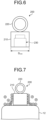
FIG. 6 is a diagram for illustration of an example of a configuration of a conventional surface treatment jig. Asurface treatment jig 200 illustrated inFIG. 6 has asupport portion 210 to support theport 13, thesupport portion 210 being columnar, and ahook portion 220 that is provided on an opposite side of thesupport portion 210 and that is ring-shaped, the opposite side being opposite to a side where theport 13 is connected. Thesupport portion 210 has ahole portion 230 formed therein, thehole portion 230 being bottomed. An inner wall of thehole portion 230 has a threaded portion formed thereon and having grooved and ridged shapes to be in threaded engagement with theport 13. Thesupport portion 210 extends with a uniform diameter and this diameter D210 is equivalent to the diameter of thebottom portion 111. -
FIG. 7 is a diagram (Part 2) illustrating a mode of adhesion of metallic ions in surface treatment. In a case where surface treatment is performed by use of thesurface treatment jig 200 illustrated inFIG. 6 , at a corner portion between a surface of thesurface treatment jig 200 and the surface of the exterior body connected with thesupport portion 210, a high electric current portion and a low electric current portion are generated and cations may not adhere to the low electric current portion. InFIG. 7 , cations illustrated with hatching are unable to be bonded to anions. Therefore, the metallic coating may be not formed or the coating may decrease in coating thickness, at the corner portion. - The following description is on results of surface treatment by use of the
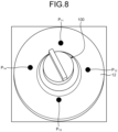
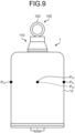
surface treatment jig 100 illustrated inFIG. 3 and measurement of coating thicknesses.FIG. 8 andFIG. 9 are diagrams illustrating coating thickness measurement positions on the exterior body that has been subjected to the surface treatment. For the exterior body that has been subjected to the surface treatment, four measurement positions (positions P11 to P14) evenly spaced out were set at the joint portion between theshell 12 and theport 13 and four measurement positions (positions P21 to P24) evenly spaced out in a circumferential direction were set on a lateral surface of theshell 12. A measurement result at each of these positions is a coating thickness at that position, the coating thickness being the mean of coating thicknesses measured for two points at that position. The positions P11 to P14 are set at positions within 3 mm from a weld between theshell 12 and theport 13. - Furthermore, in this experiment, the surface treatment was performed with the voltage and the processing time period changed. Specifically, zinc plating was performed in four patterns: (1) at 7 V for 25 minutes; (2) at 7 V for 30 minutes; (3) at 7 V for 35 minutes; and (4) at 8 V for 40 minutes.
-
FIG. 10 is a diagram illustrating minimum values from the coating thickness measurement results at the measurement positions illustrated inFIG. 8 .FIG. 11 is a diagram illustrating maximum values from the coating thickness measurement results at the measurement positions illustrated inFIG. 8 . Furthermore,FIG. 12 is a diagram illustrating minimum values from the coating thickness measurement results at the measurement positions illustrated inFIG. 9 .FIG. 13 is a diagram illustrating maximum values from the coating thickness measurement results at the measurement positions illustrated inFIG. 9 . The vertical axes represent coating thickness in units of um. InFIG. 10 to FIG. 13 , for each set of measurement conditions, the mean value of coating thicknesses at the measurement positions is plotted and the maximum values and minimum values are represented by error bars. - As illustrated in
FIG. 10 and FIG. 11 , at the joint portion between theshell 12 and theport 13, the coating thicknesses are 5 um or more for the patterns (1) to (4) (seeFIG. 10 ) and differences between the maximum values and the minimum values are 10 um or less. On the other hand, as illustrated inFIG. 12 and FIG. 13 , at a side surface portion of theshell 12, the coating thicknesses are 5 um or more for the patterns (1) to (4). It can thus be said that performing the surface treatment by using thesurface treatment jig 100 results in sufficient coating thickness of the coating at the joint portion between theshell 12 and theport 13 and ensures the coating thickness of the coating formed near the jig. - In this embodiment, because the
surface treatment jig 100 is configured to include thesupport portion 110 to support theport 13, thesupport portion 110 having a shape tapered toward thehook portion 120, the electric current difference at the surface of the exterior body is minimized and the formation of the coating on the surface of the exterior body is ensured. This embodiment enables minimization of reduction in coating thickness of an exterior body in surface treatment using a jig. - A first modified example of the surface treatment jig according to the present invention will be described next by reference to
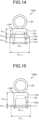
FIG. 14. FIG. 14 is a diagram for illustration of a configuration of a surface treatment jig according to the first modified example. The same reference sign is assigned to any portion that is the same as that of thesurface treatment jig 100 according to the embodiment. - A
surface treatment jig 100A has asupport portion 110A to support theport 13, and thehook portion 120 that is provided on an opposite side of thesupport portion 110A and that is ring-shaped, the opposite side being opposite to a side where theport 13 is connected. - The
support portion 110A has: abottom portion 111A positioned at an opposite end of thesupport portion 110A, the opposite end being opposite to the end where thehook portion 120 is; thehead portion 112 connected with thehook portion 120; and anintermediate portion 113A provided between thebottom portion 111A and thehead portion 112. Thesupport portion 110A has, formed therein, thehole portion 130 extending from thebottom portion 111A to thehead portion 112 and being bottomed. The inner wall of thehole portion 130 has the threadedportion 130a formed thereon and having grooved and ridged shapes to be in threaded engagement with theport 13. - The
intermediate portion 113A has a hollow truncated cone shape, one end connected with thebottom portion 111A, and the other end connected with thehead portion 112. Thehead portion 112 has the outer circumference having the diameter D112 smaller than a diameter D111A of thebottom portion 111A. Thebottom portion 111A has a height H111A smaller than the sum (H112 + H113A) of the height H112 of thehead portion 112 and a height H113A of theintermediate portion 113A. The height H111A is also larger than the height H111 of thebottom portion 111. For example, thebottom portion 111A has a diameter of 27 mm, the height H111A of thebottom portion 111A is 10 mm, and an angle θ formed between an outer surface of theintermediate portion 113A and a lateral surface of thebottom portion 111A is 45°. - Because the
surface treatment jig 100A has a shape tapered from thebottom portion 111A to thehead portion 112, cations adhere to a surface of thesurface treatment jig 100A and the surface of the exterior body connected with thesupport portion 110A due to the elimination of the electric current difference, similarly to the embodiment. - In this first modified example, similarly to the embodiment, because the
surface treatment jig 100A is configured to include thesupport portion 110A to support theport 13, thesupport portion 110A having a shape tapered toward thehook portion 120, the electric current difference at the surface of the exterior body is minimized and the formation of the coating on the surface of the exterior body is ensured. This first modified example enables minimization of reduction in coating thickness of an exterior body in surface treatment using a jig. - A second modified example of the surface treatment jig according to the present invention will be described next by reference to
FIG. 15. FIG. 15 is a diagram for illustration of a configuration of a surface treatment jig according to the second modified example. The same reference sign is assigned to any portion that is the same as that of thesurface treatment jig 100 according to the embodiment. - A
surface treatment jig 100B has asupport portion 110B to support theport 13, and ahook portion 120 that is provided on an opposite side of thesupport portion 110B and that is ring-shaped, the opposite side being opposite to a side where theport 13 is connected. - The
support portion 110B has thebottom portion 111 positioned at an opposite end of thesupport portion 110B, the opposite end being opposite to an end where thehook portion 120 is, and ahead portion 112A having one end connected with thebottom portion 111 and the other end connected with thehook portion 120. Thesupport portion 110B has, formed therein, thehole portion 130 extending from thebottom portion 111 to thehead portion 112A and being bottomed. The inner wall of thehole portion 130 has the threadedportion 130a formed thereon and having grooved and ridged shapes to be in threaded engagement with theport 13. Thesupport portion 110B is composed of thebottom portion 111 and thehead portion 112A and has a hollow cylindrical shape having a stepped shape, with a diameter near thehook portion 120 being smaller than a diameter near the opposite end. - The
head portion 112A has an outer circumference with a diameter D112A smaller than the diameter D111 of thebottom portion 111. The height H111 of thebottom portion 111 is smaller (lower) than a height H112A of thehead portion 112. For example, the height H112A of thehead portion 112A is 24 mm. - Because the
surface treatment jig 100B has a shape tapered from thebottom portion 111 to thehead portion 112A and the height of thebottom portion 111 has been set to the height H111 that minimizes the electric current difference, cations are bonded to anions on the surface of the exterior body connected with thesupport portion 110B of thesurface treatment jig 100B. - In this second modified example, similarly to the embodiment, because the
surface treatment jig 100B is configured to include thesupport portion 110B to support theport 13, thesupport portion 110B having the shape tapered toward thehook portion 120, the electric current difference at the surface of the exterior body is minimized and the formation of the coating on the surface of the exterior body is ensured. This second modified example enables minimization of reduction in coating thickness of an exterior body in surface treatment using a jig. - Some modes for implementing the present invention have been described thus far, but the present invention is not to be limited only to the above described embodiment. For example, in the examples described above with respect to the embodiment and the modified examples, the intermediate portion has a frustum shape with the outer peripheral lateral surface forming an inclined surface, but the intermediate portion may have a hollow cylindrical shape extending with a diameter smaller than the diameter of the head portion and the support portion as a whole may thus be recessed at a middle portion thereof.
- The present invention may thus include various embodiments not described herein, and various design changes, for example, may be made without departing from the technical ideas determined by the claims.
- As described hereinbefore, a surface treatment jig according to the present invention is suitable for minimizing reduction in coating thickness of a coating resulting from surface treatment.
-
- 1 ACCUMULATOR
- 11 BOTTOM
- 12 SHELL
- 13 PORT
- 14 BELLOWS
- 15 CAP BODY PORTION
- 16 CAP ELASTIC PORTION
- 17 GUIDE BELLOWS
- 100, 100A, 100B SURFACE TREATMENT JIG
- 110, 110A SUPPORT PORTION
- 111, 111A BOTTOM PORTION
- 112, 112A HEAD PORTION
- 113, 113A INTERMEDIATE PORTION
- 114 PACKING
- 120 HOOK PORTION
- 130 HOLE PORTION
- 140 ANODE
- 150 SUPPORT MEMBER
Claims (4)
- A surface treatment jig for performing surface treatment of an exterior body of an accumulator including a bottom, a shell and a port in a state where the surface treatment jig is connected to the exterior body and supports the exterior body, the surface treatment jig comprising:a support portion configured to support the accumulator; anda hook portion connected with the support portion, whereinthe support portion has a shape tapered near the hook portion.
- The surface treatment jig according to claim 1, whereinthe support portion includes:a head portion provided on a side near the hook portion;a bottom portion provided on an opposite side of the side near the head portion; andan intermediate portion provided between the head portion and the bottom portion, andthe bottom portion has a height smaller than a sum of heights of the head portion and the intermediate portion.
- The surface treatment jig according to claim 2, wherein the intermediate portion has a frustum shape.
- The surface treatment jig according to claim 1, whereinthe support portion includes:a head portion provided on a side near the hook portion; anda bottom portion provided on an opposite side of the side near the head portion; andthe bottom portion has a height smaller than a height of the head portion.
Applications Claiming Priority (2)
| Application Number | Priority Date | Filing Date | Title |
|---|---|---|---|
| JP2022047104A JP7773414B2 (en) | 2022-03-23 | 2022-03-23 | Surface treatment jig |
| PCT/JP2023/011288 WO2023182375A1 (en) | 2022-03-23 | 2023-03-22 | Surface treatment jig |
Publications (2)
| Publication Number | Publication Date |
|---|---|
| EP4467688A1 true EP4467688A1 (en) | 2024-11-27 |
| EP4467688A4 EP4467688A4 (en) | 2025-06-25 |
Family
ID=88101580
Family Applications (1)
| Application Number | Title | Priority Date | Filing Date |
|---|---|---|---|
| EP23774970.0A Pending EP4467688A4 (en) | 2022-03-23 | 2023-03-22 | SURFACE TREATMENT TEMPLATE |
Country Status (6)
| Country | Link |
|---|---|
| US (1) | US20250135481A1 (en) |
| EP (1) | EP4467688A4 (en) |
| JP (1) | JP7773414B2 (en) |
| KR (1) | KR20240128043A (en) |
| CN (1) | CN118679281A (en) |
| WO (1) | WO2023182375A1 (en) |
Family Cites Families (12)
| Publication number | Priority date | Publication date | Assignee | Title |
|---|---|---|---|---|
| CH593720A5 (en) * | 1975-01-17 | 1977-12-15 | Gema Ag | |
| JPS543853A (en) * | 1977-06-13 | 1979-01-12 | Onoda Cement Co Ltd | Removing device of excess powder for electrostatidc powder coating |
| JPS5440245A (en) * | 1977-09-05 | 1979-03-29 | Sankyo Aruminiumu Kougiyou Kk | Supporting method of extruion shaped member for urface treating |
| JPS57165065A (en) * | 1981-04-01 | 1982-10-09 | Kansai Paint Co Ltd | Inhibition of adhesion of powdery paint to hanging support |
| JPH05246682A (en) * | 1992-03-04 | 1993-09-24 | Iida Tekko:Kk | Cylinder suspending tool |
| JP2002228100A (en) * | 2001-01-30 | 2002-08-14 | In System Kk | Vessel opening/closing valve unit, and method for cleaning inside of vessel |
| JP3844064B2 (en) * | 2002-03-25 | 2006-11-08 | 株式会社アドヴィックス | Bellows hydraulic accumulator |
| JP4718129B2 (en) * | 2003-07-30 | 2011-07-06 | 日本発條株式会社 | Brake system parts for vehicles |
| JP2007215768A (en) * | 2006-02-16 | 2007-08-30 | Sri Sports Ltd | Hanging jig for painting tubular body and method for manufacturing golf club |
| JP5897327B2 (en) | 2011-12-28 | 2016-03-30 | 興亜硝子株式会社 | Workpiece conveying apparatus and electrostatic coating method |
| CN104449193A (en) * | 2014-12-26 | 2015-03-25 | 常熟市福王制冷器材有限公司 | Liquid reservoir for refrigeration equipment |
| CN109402692B (en) * | 2018-12-07 | 2020-04-21 | 中国航发南方工业有限公司 | Part is electroplated with dress hanger clamp to excircle part |
-
2022
- 2022-03-23 JP JP2022047104A patent/JP7773414B2/en active Active
-
2023
- 2023-03-22 KR KR1020247024626A patent/KR20240128043A/en active Pending
- 2023-03-22 CN CN202380020810.0A patent/CN118679281A/en active Pending
- 2023-03-22 EP EP23774970.0A patent/EP4467688A4/en active Pending
- 2023-03-22 US US18/834,762 patent/US20250135481A1/en active Pending
- 2023-03-22 WO PCT/JP2023/011288 patent/WO2023182375A1/en not_active Ceased
Also Published As
| Publication number | Publication date |
|---|---|
| JP2023140997A (en) | 2023-10-05 |
| WO2023182375A1 (en) | 2023-09-28 |
| CN118679281A (en) | 2024-09-20 |
| EP4467688A4 (en) | 2025-06-25 |
| KR20240128043A (en) | 2024-08-23 |
| US20250135481A1 (en) | 2025-05-01 |
| JP7773414B2 (en) | 2025-11-19 |
Similar Documents
| Publication | Publication Date | Title |
|---|---|---|
| US11255468B2 (en) | Gasket for fluid coupling, and fluid coupling | |
| EP2290331B1 (en) | Electromagnetic flowmeter | |
| US8298383B2 (en) | Cylindrical membranous electrolytic cell and assembled anode and diaphragm | |
| US20250135481A1 (en) | Surface treatment jig | |
| US9790611B2 (en) | Partial anodizing apparatus and anodizing method using the same | |
| US20220267922A1 (en) | Surface treatment device | |
| CN210769634U (en) | Hydraulic cylinder sealing ring and hydraulic cylinder | |
| US20250215905A1 (en) | Accumulator | |
| US20140175759A1 (en) | Gasket and sealing structure | |
| EP2492021A1 (en) | Fastener for use in electrodeposition and method | |
| JP2015059265A (en) | Partial surface treatment equipment | |
| US11174880B2 (en) | Accumulator | |
| CN210600160U (en) | Corrosion-resistant connection structure | |
| JP5361627B2 (en) | Vacuum valve housing and vacuum valve | |
| CN216951317U (en) | Bearing inner race anti-phosphorization device | |
| JPH03285097A (en) | Anode for electroplating and electroplating method | |
| JP5150104B2 (en) | ELECTROLYTIC CELL AND ELECTROLYTIC WATER GENERATOR HAVING THE SAME | |
| CN213397513U (en) | A insert leak hunting joint soon for electrophoresis film | |
| JP2019010622A (en) | Masking jig for painting, jig for removing it, and set thereof | |
| US20250146513A1 (en) | Cap bellows assembly and accumulator | |
| CN110418900B (en) | Pressure accumulator | |
| US20220042600A1 (en) | Glass reinforced epoxy kammprofile sealing gasket | |
| EP4520982A1 (en) | Structure comprising hollow structural elements connected together, assembly comprising such a structure, and corresponding manufacturing method | |
| CN217060294U (en) | Installation base of electric field potential measuring device for ship | |
| JPH06200901A (en) | Wave type container for wave pattern type diaphragm |
Legal Events
| Date | Code | Title | Description |
|---|---|---|---|
| STAA | Information on the status of an ep patent application or granted ep patent |
Free format text: STATUS: THE INTERNATIONAL PUBLICATION HAS BEEN MADE |
|
| PUAI | Public reference made under article 153(3) epc to a published international application that has entered the european phase |
Free format text: ORIGINAL CODE: 0009012 |
|
| STAA | Information on the status of an ep patent application or granted ep patent |
Free format text: STATUS: REQUEST FOR EXAMINATION WAS MADE |
|
| 17P | Request for examination filed |
Effective date: 20240820 |
|
| AK | Designated contracting states |
Kind code of ref document: A1 Designated state(s): AL AT BE BG CH CY CZ DE DK EE ES FI FR GB GR HR HU IE IS IT LI LT LU LV MC ME MK MT NL NO PL PT RO RS SE SI SK SM TR |
|
| REG | Reference to a national code |
Ref country code: DE Ref legal event code: R079 Free format text: PREVIOUS MAIN CLASS: C25D0017080000 Ipc: C25D0017060000 |
|
| A4 | Supplementary search report drawn up and despatched |
Effective date: 20250526 |
|
| RIC1 | Information provided on ipc code assigned before grant |
Ipc: C25D 7/00 20060101ALI20250521BHEP Ipc: C25D 7/04 20060101ALI20250521BHEP Ipc: F15B 1/10 20060101ALI20250521BHEP Ipc: C25D 17/06 20060101AFI20250521BHEP |
|
| DAV | Request for validation of the european patent (deleted) | ||
| DAX | Request for extension of the european patent (deleted) |