EP4467670A1 - Wheel bearing device - Google Patents
Wheel bearing device Download PDFInfo
- Publication number
- EP4467670A1 EP4467670A1 EP22922145.2A EP22922145A EP4467670A1 EP 4467670 A1 EP4467670 A1 EP 4467670A1 EP 22922145 A EP22922145 A EP 22922145A EP 4467670 A1 EP4467670 A1 EP 4467670A1
- Authority
- EP
- European Patent Office
- Prior art keywords
- induction
- hardened part
- hardened
- bearing device
- vehicle wheel
- Prior art date
- Legal status (The legal status is an assumption and is not a legal conclusion. Google has not performed a legal analysis and makes no representation as to the accuracy of the status listed.)
- Pending
Links
Images




Classifications
-
- C—CHEMISTRY; METALLURGY
- C21—METALLURGY OF IRON
- C21D—MODIFYING THE PHYSICAL STRUCTURE OF FERROUS METALS; GENERAL DEVICES FOR HEAT TREATMENT OF FERROUS OR NON-FERROUS METALS OR ALLOYS; MAKING METAL MALLEABLE, e.g. BY DECARBURISATION OR TEMPERING
- C21D9/00—Heat treatment, e.g. annealing, hardening, quenching or tempering, adapted for particular articles; Furnaces therefor
- C21D9/40—Heat treatment, e.g. annealing, hardening, quenching or tempering, adapted for particular articles; Furnaces therefor for rings; for bearing races
-
- F—MECHANICAL ENGINEERING; LIGHTING; HEATING; WEAPONS; BLASTING
- F16—ENGINEERING ELEMENTS AND UNITS; GENERAL MEASURES FOR PRODUCING AND MAINTAINING EFFECTIVE FUNCTIONING OF MACHINES OR INSTALLATIONS; THERMAL INSULATION IN GENERAL
- F16C—SHAFTS; FLEXIBLE SHAFTS; ELEMENTS OR CRANKSHAFT MECHANISMS; ROTARY BODIES OTHER THAN GEARING ELEMENTS; BEARINGS
- F16C19/00—Bearings with rolling contact, for exclusively rotary movement
- F16C19/02—Bearings with rolling contact, for exclusively rotary movement with bearing balls essentially of the same size in one or more circular rows
- F16C19/14—Bearings with rolling contact, for exclusively rotary movement with bearing balls essentially of the same size in one or more circular rows for both radial and axial load
- F16C19/18—Bearings with rolling contact, for exclusively rotary movement with bearing balls essentially of the same size in one or more circular rows for both radial and axial load with two or more rows of balls
- F16C19/181—Bearings with rolling contact, for exclusively rotary movement with bearing balls essentially of the same size in one or more circular rows for both radial and axial load with two or more rows of balls with angular contact
- F16C19/183—Bearings with rolling contact, for exclusively rotary movement with bearing balls essentially of the same size in one or more circular rows for both radial and axial load with two or more rows of balls with angular contact with two rows at opposite angles
- F16C19/184—Bearings with rolling contact, for exclusively rotary movement with bearing balls essentially of the same size in one or more circular rows for both radial and axial load with two or more rows of balls with angular contact with two rows at opposite angles in O-arrangement
- F16C19/186—Bearings with rolling contact, for exclusively rotary movement with bearing balls essentially of the same size in one or more circular rows for both radial and axial load with two or more rows of balls with angular contact with two rows at opposite angles in O-arrangement with three raceways provided integrally on parts other than race rings, e.g. third generation hubs
-
- C—CHEMISTRY; METALLURGY
- C21—METALLURGY OF IRON
- C21D—MODIFYING THE PHYSICAL STRUCTURE OF FERROUS METALS; GENERAL DEVICES FOR HEAT TREATMENT OF FERROUS OR NON-FERROUS METALS OR ALLOYS; MAKING METAL MALLEABLE, e.g. BY DECARBURISATION OR TEMPERING
- C21D1/00—General methods or devices for heat treatment, e.g. annealing, hardening, quenching or tempering
- C21D1/06—Surface hardening
- C21D1/09—Surface hardening by direct application of electrical or wave energy; by particle radiation
- C21D1/10—Surface hardening by direct application of electrical or wave energy; by particle radiation by electric induction
-
- F—MECHANICAL ENGINEERING; LIGHTING; HEATING; WEAPONS; BLASTING
- F16—ENGINEERING ELEMENTS AND UNITS; GENERAL MEASURES FOR PRODUCING AND MAINTAINING EFFECTIVE FUNCTIONING OF MACHINES OR INSTALLATIONS; THERMAL INSULATION IN GENERAL
- F16C—SHAFTS; FLEXIBLE SHAFTS; ELEMENTS OR CRANKSHAFT MECHANISMS; ROTARY BODIES OTHER THAN GEARING ELEMENTS; BEARINGS
- F16C33/00—Parts of bearings; Special methods for making bearings or parts thereof
- F16C33/30—Parts of ball or roller bearings
- F16C33/58—Raceways; Race rings
- F16C33/64—Special methods of manufacture
-
- B—PERFORMING OPERATIONS; TRANSPORTING
- B60—VEHICLES IN GENERAL
- B60B—VEHICLE WHEELS; CASTORS; AXLES FOR WHEELS OR CASTORS; INCREASING WHEEL ADHESION
- B60B27/00—Hubs
- B60B27/0078—Hubs characterised by the fixation of bearings
-
- F—MECHANICAL ENGINEERING; LIGHTING; HEATING; WEAPONS; BLASTING
- F16—ENGINEERING ELEMENTS AND UNITS; GENERAL MEASURES FOR PRODUCING AND MAINTAINING EFFECTIVE FUNCTIONING OF MACHINES OR INSTALLATIONS; THERMAL INSULATION IN GENERAL
- F16C—SHAFTS; FLEXIBLE SHAFTS; ELEMENTS OR CRANKSHAFT MECHANISMS; ROTARY BODIES OTHER THAN GEARING ELEMENTS; BEARINGS
- F16C2202/00—Solid materials defined by their properties
- F16C2202/02—Mechanical properties
- F16C2202/04—Hardness
-
- F—MECHANICAL ENGINEERING; LIGHTING; HEATING; WEAPONS; BLASTING
- F16—ENGINEERING ELEMENTS AND UNITS; GENERAL MEASURES FOR PRODUCING AND MAINTAINING EFFECTIVE FUNCTIONING OF MACHINES OR INSTALLATIONS; THERMAL INSULATION IN GENERAL
- F16C—SHAFTS; FLEXIBLE SHAFTS; ELEMENTS OR CRANKSHAFT MECHANISMS; ROTARY BODIES OTHER THAN GEARING ELEMENTS; BEARINGS
- F16C2204/00—Metallic materials; Alloys
- F16C2204/60—Ferrous alloys, e.g. steel alloys
- F16C2204/64—Medium carbon steel, i.e. carbon content from 0.4 to 0,8 wt%
-
- F—MECHANICAL ENGINEERING; LIGHTING; HEATING; WEAPONS; BLASTING
- F16—ENGINEERING ELEMENTS AND UNITS; GENERAL MEASURES FOR PRODUCING AND MAINTAINING EFFECTIVE FUNCTIONING OF MACHINES OR INSTALLATIONS; THERMAL INSULATION IN GENERAL
- F16C—SHAFTS; FLEXIBLE SHAFTS; ELEMENTS OR CRANKSHAFT MECHANISMS; ROTARY BODIES OTHER THAN GEARING ELEMENTS; BEARINGS
- F16C2223/00—Surface treatments; Hardening; Coating
- F16C2223/10—Hardening, e.g. carburizing, carbo-nitriding
- F16C2223/18—Hardening, e.g. carburizing, carbo-nitriding with induction hardening
-
- F—MECHANICAL ENGINEERING; LIGHTING; HEATING; WEAPONS; BLASTING
- F16—ENGINEERING ELEMENTS AND UNITS; GENERAL MEASURES FOR PRODUCING AND MAINTAINING EFFECTIVE FUNCTIONING OF MACHINES OR INSTALLATIONS; THERMAL INSULATION IN GENERAL
- F16C—SHAFTS; FLEXIBLE SHAFTS; ELEMENTS OR CRANKSHAFT MECHANISMS; ROTARY BODIES OTHER THAN GEARING ELEMENTS; BEARINGS
- F16C2240/00—Specified values or numerical ranges of parameters; Relations between them
- F16C2240/30—Angles, e.g. inclinations
-
- F—MECHANICAL ENGINEERING; LIGHTING; HEATING; WEAPONS; BLASTING
- F16—ENGINEERING ELEMENTS AND UNITS; GENERAL MEASURES FOR PRODUCING AND MAINTAINING EFFECTIVE FUNCTIONING OF MACHINES OR INSTALLATIONS; THERMAL INSULATION IN GENERAL
- F16C—SHAFTS; FLEXIBLE SHAFTS; ELEMENTS OR CRANKSHAFT MECHANISMS; ROTARY BODIES OTHER THAN GEARING ELEMENTS; BEARINGS
- F16C2240/00—Specified values or numerical ranges of parameters; Relations between them
- F16C2240/40—Linear dimensions, e.g. length, radius, thickness, gap
- F16C2240/60—Thickness, e.g. thickness of coatings
-
- F—MECHANICAL ENGINEERING; LIGHTING; HEATING; WEAPONS; BLASTING
- F16—ENGINEERING ELEMENTS AND UNITS; GENERAL MEASURES FOR PRODUCING AND MAINTAINING EFFECTIVE FUNCTIONING OF MACHINES OR INSTALLATIONS; THERMAL INSULATION IN GENERAL
- F16C—SHAFTS; FLEXIBLE SHAFTS; ELEMENTS OR CRANKSHAFT MECHANISMS; ROTARY BODIES OTHER THAN GEARING ELEMENTS; BEARINGS
- F16C2326/00—Articles relating to transporting
- F16C2326/01—Parts of vehicles in general
- F16C2326/02—Wheel hubs or castors
-
- Y—GENERAL TAGGING OF NEW TECHNOLOGICAL DEVELOPMENTS; GENERAL TAGGING OF CROSS-SECTIONAL TECHNOLOGIES SPANNING OVER SEVERAL SECTIONS OF THE IPC; TECHNICAL SUBJECTS COVERED BY FORMER USPC CROSS-REFERENCE ART COLLECTIONS [XRACs] AND DIGESTS
- Y02—TECHNOLOGIES OR APPLICATIONS FOR MITIGATION OR ADAPTATION AGAINST CLIMATE CHANGE
- Y02P—CLIMATE CHANGE MITIGATION TECHNOLOGIES IN THE PRODUCTION OR PROCESSING OF GOODS
- Y02P10/00—Technologies related to metal processing
- Y02P10/25—Process efficiency
Definitions
- the present invention relates to a bearing device for a vehicle wheel.
- induction hardened depth a hardened layer depth created by induction hardening
- increasing the hardened layer depth created by induction hardening has an adverse effect such as quenching crack and shortened bearing life due to deterioration in crystal grain size caused by overheating.
- Patent Literature 1 discloses a bearing unit for a vehicle wheel (bearing device for a vehicle wheel) in which effective hardened layer depths created by induction hardening of an outer ring raceway on the outer side (outer-side raceway surface) and an outer ring raceway on the inner side (inner-side raceway surface) can be set appropriately in accordance with the characteristics of loads that the raceway surfaces receive.
- This bearing unit for a vehicle wheel work under the most severe load that occurs on the outer side of a turn when a car driven normally turns in which, generally, the raceway surface on the inner-side receives a high load.
- Patent Literature 1 JP-A 2007-332998 Gazette
- Patent Literature 1 application of the bearing unit for a vehicle wheel is not clear, and the purpose for improvement in indentation resistance, improvement in wear resistance, improvement in bearing life, and the like are not described. That is, a configuration directed to improvement of indentation resistance is not disclosed.
- increasing the hardened layer depth created by induction hardening as a way of improving indentation resistance may cause a quenching crack or deterioration in crystal grain sizes.
- An object of the present invention is to provide a bearing device for a vehicle wheel with improved indentation resistance at an outer-side of an outer member while minimizing a quenching crack and deterioration in crystal grain sizes.
- the present invention includes an outer member having a double-row of outer raceway surfaces on an inner circumference, an inner member having a double-row of inner raceway surfaces facing the double-row of outer raceway surfaces, and a double-row of rolling elements rollably held between the outer raceway surfaces of the outer member and the inner raceway surfaces of the inner member, in which the outer member has an inner-side induction-hardened part formed by induction hardening along the outer raceway surface on an inner-side, and an outer-side induction-hardened part formed by induction hardening along the outer raceway surface on an outer-side, a hardened layer depth of the outer-side induction-hardened part is larger than a hardened layer depth of the inner-side induction-hardened part, and the inner-side induction-hardened part and the outer-side induction-hardened part are separated from each other.
- the present invention includes an outer member having a double-row of outer raceway surfaces on an inner circumference, an inner member having a double-row of inner raceway surfaces facing the double-row of outer raceway surfaces, and a double-row of rolling elements rollably held between the outer raceway surfaces of the outer member and the inner raceway surfaces of the inner member, in which the outer member has an inner-side induction-hardened part formed by induction hardening along the outer raceway surface on an inner-side, and an outer-side induction-hardened part formed by induction hardening along the outer raceway surface on an outer-side, a hardened layer depth of the outer-side induction-hardened part is deeper than a hardened layer depth of the inner-side induction-hardened part, and the inner-side induction-hardened part and the outer-side induction-hardened part are joined.
- indentation resistance at an outer-side of an outer member can be improved while minimizing a quenching crack and deterioration in crystal grain size. Furthermore, according to the present invention, the indentation resistance of an axially inner side (inner-side) portion of an outer raceway surface on the outer-side can be improved.
- a bearing device for a vehicle wheel 1 The overall configuration of a bearing device for a vehicle wheel 1 will be described with reference to FIG. 1 .
- “inner-side” represents the vehicle body side of the bearing device for a vehicle wheel 1 attached to a vehicle body
- outer-side represents the vehicle wheel side of the bearing device for a vehicle wheel 1 attached to the vehicle body.
- “Axial direction” represents the direction along a rotation axis A of the bearing device for a vehicle wheel 1.
- “Radial direction” represents the direction orthogonal to the rotation axis A of the bearing device for a vehicle wheel 1.
- “Circumferential direction” represents the direction along an arc centered on the rotation axis A of the bearing device for a vehicle wheel 1.
- “Axially outer side” represents the direction away from an annular space S along the rotation axis A
- “axially inner side” represents the direction to approach the annular space S along the rotation axis A.
- the bearing device for a vehicle wheel 1 supports a vehicle wheel to rotate in a suspension device of a vehicle such as a car.
- the bearing device for a vehicle wheel 1 includes an outer ring 2, a hub ring 3, an inner ring 4, rolling elements 5, an inner-side seal member 6, and an outer-side seal member 7.
- the outer ring 2 which is an outer member, supports the hub ring 3 and the inner ring 4.
- a seal fitting portion 2b to which the inner-side seal member 6 is fitted is provided on an inner circumferential surface of an inner-side end 2a of the outer ring 2.
- a seal fitting portion 2d to which the outer-side seal member 7 is fitted is provided on an inner circumferential surface of an outer-side end 2c of the outer ring 2.
- a vehicle body mounting flange 2f is integrally provided on an outer circumferential surface 2e of the outer ring 2.
- a fixing bolt 8a for fastening together the outer ring 2 and a knuckle 8 is inserted in the vehicle body mounting flange 2f.
- On the inner circumferential surface of the outer ring 2 a double-row of outer raceway surfaces 2g and 2h is provided along the circumferential direction respectively on the inner-side and the outer-side.
- An inner member includes the hub ring 3 and the inner ring 4.
- the hub ring 3 supports a vehicle wheel to rotate (not illustrated).
- a radially reduced small-diameter stepped portion 3a extending in the axial direction is provided at an inner-side end of the outer circumferential surface of the hub ring 3.
- a vehicle wheel mounting flange 3b for mounting a vehicle wheel is integrally provided on an outer-side end of the hub ring 3.
- a hub bolt 3c for fastening the hub ring 3 to a vehicle wheel or a braking device is press-fitted in the vehicle wheel mounting flange 3b.
- a tapped hole for fastening a hub bolt may be provided in the vehicle wheel mounting flange 3b.
- an inner raceway surface 3d facing the outer raceway surface 2h on the outer-side is provided on the outer circumferential surface on the outer-side of the hub ring 3. That is, on the outer-side of the inner member, the hub ring 3 forms the inner raceway surface 3d.
- a sliding surface 3e against which the outer-side seal member 7 slides is provided on the proximal side of the vehicle wheel mounting flange 3b of the hub ring 3.
- the inner ring 4 is press-fitted onto the small-diameter stepped portion 3a of the hub ring 3.
- the inner ring 4 applies a pre-load to the rolling elements 5.
- On the outer circumferential surface of the inner ring 4 an inner raceway surface 4a facing the outer raceway surface 2g on the inner-side is provided. That is, on the inner-side of the inner member, the inner ring 4 forms the inner raceway surface 4a.
- a seal fitting portion 4b to which the inner-side seal member 6 is fitted is provided on the outer circumferential surface of an inner-side end 4c of the inner ring 4.
- the rolling elements 5 are balls.
- the rolling elements 5 on the inner-side and the rolling elements 5 on the outer-side are held by cages 51.
- the rolling elements 5 on the inner-side are held between the inner raceway surface 4a of the inner ring 4 and the outer raceway surface 2g on the inner-side of the outer ring 2 so as to roll.
- the rolling elements 5 on the outer-side are held between the inner raceway surface 3d of the hub ring 3 and the outer raceway surface 2h on the outer-side of the outer ring 2 so as to roll. That is, the rolling elements 5 on the inner-side and the rolling elements 5 on the outer-side are held between the raceway surfaces of the outer member and the inner member so as to roll.
- the bearing device for a vehicle wheel 1 the outer ring 2, the hub ring 3, the inner ring 4, and the double-row of rolling elements 5 constitute a double-row angular ball bearing.
- the bearing device for a vehicle wheel 1 may constitute a double-row tapered roller bearing instead of the double-row angular ball bearing.
- the inner-side seal member 6 and the outer-side seal member 7, which are seal members, are each a sealing member that closes an open end of the annular space S formed by the outer member and the inner member.
- the inner-side seal member 6 is attached to an inner-side open end formed between the outer ring 2 and the inner ring 4 of the annular space S.
- the outer-side seal member 7 is attached to an outer-side open end formed between the outer ring 2 and the hub ring 3 of the annular space S.
- the outer ring 2 is made of medium-carbon steel or high-carbon steel containing 0.40 to 0.80 wt% of carbon such as S53C.
- the outer ring 2 is subjected to induction hardening along the outer raceway surfaces 2g and 2h in a heat treatment step.
- An induction-hardened part 9 is formed in the outer ring 2 as a result of the heat treatment step, thereby improving surface hardness and strength.
- the induction-hardened part 9 includes an inner-side induction-hardened part 9a that has been subjected to induction hardening along the outer raceway surface 2g on the inner-side, and an outer-side induction-hardened part 9b that has been subjected to induction hardening along the outer raceway surface 2h on the outer-side.
- a hardened layer depth D of the outer-side induction-hardened part 9b is deeper than a hardened layer depth E of the inner-side induction-hardened part 9a.
- the hardened layer depth D of the outer-side induction-hardened part 9b and the hardened layer depth E of the inner-side induction-hardened part 9a each indicate a hardened layer depth at an angle ⁇ of 30 to 45 degrees with respect to the rotation axis A.
- the angle ⁇ with respect to the rotation axis A on the inner-side is an angle to one side and the angle ⁇ with respect to the rotation axis A on the outer-side is an angle to the other side.
- the induction-hardened part 9 has a surface hardness of 58 to 64 HRC.
- the hardened layer depth of the induction-hardened part 9 is the depth of a portion having a hardness of 78% or more of the surface hardness of the induction-hardened part 9.
- the hardened layer depth D of the outer-side induction-hardened part 9b is 0.5 to 2.2 mm deeper than the hardened layer depth E of the inner-side induction-hardened part 9a at the same angle in axial cross sections of the same rotational phase (circumferential position) under the same definition of the hardened layer depth.
- the inner-side induction-hardened part 9a is formed along the entire outer raceway surface 2g on the inner-side.
- the outer-side induction-hardened part 9b is formed along the entire outer raceway surface 2h on the outer-side.
- the hardened layer depth in a direction normal to the outer raceway surface 2h of the outer-side induction-hardened part 9b the hardened layer depth in the axially inner side (inner-side) of the outer-side hardened layer depth D is deeper than the hardened layer depth in the axially outer side (outer-side) of the outer-side hardened layer depth D.
- the outer-side induction-hardened part 9b and the inner-side induction-hardened part 9a are separated from each other.
- the bearing device for a vehicle wheel 1 configured as described above, when a vehicle is large with respect to a bearing size or under a vehicle use condition with poor roadway infrastructure, happening of indentation defects in a market can be reduced by increasing only the hardened layer depth D of the outer-side induction-hardened part 9b of the outer ring 2 where a large indentation may in particular occur.
- Increasing the hardened layer depth by induction hardening may cause a quenching crack or reduction in bearing life due to deterioration in crystal grain size caused by overheating.
- the inner-side of the outer ring 2 has a low degree of freedom in changing an outside diameter C, since fitting with a peripheral component (knuckle 8) needs to be considered. Meanwhile, the outer-side of the outer ring 2 has a high degree of freedom in changing an outside diameter B, since fitting with the knuckle 8 needs not be considered.
- the outer-side outside diameter B can be set larger than the inner-side outside diameter C, and the outer ring 2 is formed to have the outer-side outside diameter B larger than the inner-side outside diameter C.
- increasing the thickness in the outer-side of the outer ring 2 can avoid a quenching crack due to insufficient thickness resulting from increasing the hardened layer depth D of the outer-side induction-hardened part 9b.
- increasing the outer-side thickness of the outer ring 2 enhances the rigidity of the outer-side of the outer ring 2, deterioration in roundness of the outer raceway surface 2h due to loading is reduced. This increases the steel ball load factor of the outer-side of the outer ring 2 and improves indentation resistance.
- the inner-side induction-hardened part 9a and the outer-side induction-hardened part 9b join at the radially inner side to be integrated.
- the induction-hardened part 9 is formed entirely on the inner circumferential surface 2j between the outer raceway surface 2g on the inner-side and the outer raceway surface 2h on the outer-side.
- a portion of the induction-hardened part 9 between the outer-side outer raceway surface 2h and the inner-side outer raceway surface 2g is formed in a wider area.
- the indentation resistance of an axially inner side (inner-side) portion of the outer-side outer raceway surface 2h can be improved.
- the inner-side of the outer ring 2 has a low degree of freedom in changing an outside diameter C, since fitting with a peripheral component (knuckle 8) needs to be considered. Meanwhile, the outer-side of the outer ring 2 has a high degree of freedom in changing an outside diameter B, since fitting with the knuckle 8 needs not be considered.
- the outer-side outside diameter B can be set larger than the inner-side outside diameter C, and the outer ring 2 is formed to have the outer-side outside diameter B larger than the inner-side outside diameter C.
- increasing the thickness of the outer-side of the outer ring 2 can avoid a quenching crack due to insufficient thickness resulting from increasing the hardened layer depth D of the outer-side induction-hardened part 9b.
- increasing the outer-side thickness of the outer ring 2 enhances the rigidity of the outer-side of the outer ring 2, deterioration in roundness of the outer raceway surface 2h due to loading is reduced. This increases the steel ball load factor of the outer-side of the outer ring 2 and improves indentation resistance.
- the outer ring 2 has a pocket 2k on each of the outer-side (axially inner side) of the seal fitting portion 2b and the inner-side (axially inner side) of the seal fitting portion 2d.
- the pocket 2k is formed in a concave curved surface (rounded shape) in a cross-sectional view.
- an inner-side end 9c of the inner-side induction-hardened part 9a is on the radially inner side of the inner-side pocket 2k
- an outer-side end 9d of the outer-side induction-hardened part 9b is on the radially inner side of the outer-side pocket 2k.
- the inner-side pocket 2k has an inside diameter G at its radially inner end.
- the inner-side induction-hardened part 9a has an outside diameter F at the inner-side end 9c thereof.
- the outside diameter F of the inner-side induction-hardened part 9a is smaller than the inside diameter G of the pocket 2k.
- the induction-hardened part 9 is not formed in the pocket 2k.
- the boundary between the induction-hardened part 9 and the portion where no induction-hardened part 9 is formed is formed in the pocket 2k, tensile stress concentration may occur at the boundary. Forming the pocket 2k as described above prevents stress concentration at the boundary. Thus, degrading of the durability of the pocket 2k can be prevented.
- the surface hardness of the rolling elements 5 is higher than the surface hardness of the outer raceway surfaces 2g and 2h, excessive radial loading on the bearing device for a vehicle wheel 1, 1A, 1B, or 1C may create an indentation on the outer raceway surfaces 2g and 2h.
- the indentation resistance at the outer-side of the outer ring 2 can be improved as described above. That is, the indentation resistance of the outer raceway surface 2h can be improved.
- the outer ring 2 has a vehicle body mounting flange 2f at the upper end on the side opposite the road.
- the moment from the vehicle wheel mounting flange 3b is readily transmitted to the upper portion of the outer-side outer raceway surface 2h, which may readily create an indentation on the outer raceway surface 2h.
- the indentation resistance at the outer-side of the outer ring 2 can be improved as described above. That is, the indentation resistance of the outer raceway surface 2h can be improved.
- the bearing devices for a vehicle wheel 1, 1A, 1B, and 1C according to the embodiments have each been described as a bearing device for a vehicle wheel having a third generation structure of rotating inner ring in which the inner raceway surface 3d for the rolling elements 5 is directly formed on the outer circumference of the hub ring 3.
- the embodiment is not limited to this configuration, and may have, for example, a second generation structure of rotating inner ring in which a pair of inner rings 4 is press-fitted and fixed to the hub ring 3.
- the bearing device for a vehicle wheel may be a third generation structure or a second generation structure of rotating outer ring.
- the above embodiments each merely illustrate a representative mode of the present invention, and various modifications can be made without departing from the gist of the present invention.
- the present invention is applicable to a bearing device for a vehicle wheel.
Landscapes
- Engineering & Computer Science (AREA)
- General Engineering & Computer Science (AREA)
- Chemical & Material Sciences (AREA)
- Mechanical Engineering (AREA)
- Crystallography & Structural Chemistry (AREA)
- Thermal Sciences (AREA)
- Physics & Mathematics (AREA)
- Materials Engineering (AREA)
- Metallurgy (AREA)
- Organic Chemistry (AREA)
- Manufacturing & Machinery (AREA)
- Rolling Contact Bearings (AREA)
- Heat Treatment Of Articles (AREA)
Abstract
Description
- The present invention relates to a bearing device for a vehicle wheel.
- In recent years, the size of a vehicle have become larger with respect to the size of a bearing device for a vehicle wheel. Meanwhile, cars are becoming widespread in markets with poor roadway infrastructure. This causes an excessive radial load applied to a vehicle wheel, which may easily create an indentation on a raceway surface. On an outer-side of an outer member, in particular, the roundness of the raceway surface is likely to be significantly deteriorated by applied load. When the steel ball load factor (ratio of the number of rolling elements receiving a load to the total number of rolling elements) is significantly reduced, a large indentation is created compared a case of the inner-side of the outer member and other components. Meanwhile, one of the most effective ways to improve indentation resistance is to increase a hardened layer depth created by induction hardening (induction hardened depth). However, increasing the hardened layer depth created by induction hardening has an adverse effect such as quenching crack and shortened bearing life due to deterioration in crystal grain size caused by overheating.
- Patent Literature 1 discloses a bearing unit for a vehicle wheel (bearing device for a vehicle wheel) in which effective hardened layer depths created by induction hardening of an outer ring raceway on the outer side (outer-side raceway surface) and an outer ring raceway on the inner side (inner-side raceway surface) can be set appropriately in accordance with the characteristics of loads that the raceway surfaces receive. This bearing unit for a vehicle wheel work under the most severe load that occurs on the outer side of a turn when a car driven normally turns in which, generally, the raceway surface on the inner-side receives a high load.
- Patent Literature 1:
JP-A 2007-332998 - However, in Patent Literature 1, application of the bearing unit for a vehicle wheel is not clear, and the purpose for improvement in indentation resistance, improvement in wear resistance, improvement in bearing life, and the like are not described. That is, a configuration directed to improvement of indentation resistance is not disclosed. In addition, as described above, increasing the hardened layer depth created by induction hardening as a way of improving indentation resistance may cause a quenching crack or deterioration in crystal grain sizes.
- An object of the present invention is to provide a bearing device for a vehicle wheel with improved indentation resistance at an outer-side of an outer member while minimizing a quenching crack and deterioration in crystal grain sizes.
- The present invention includes an outer member having a double-row of outer raceway surfaces on an inner circumference, an inner member having a double-row of inner raceway surfaces facing the double-row of outer raceway surfaces, and a double-row of rolling elements rollably held between the outer raceway surfaces of the outer member and the inner raceway surfaces of the inner member, in which the outer member has an inner-side induction-hardened part formed by induction hardening along the outer raceway surface on an inner-side, and an outer-side induction-hardened part formed by induction hardening along the outer raceway surface on an outer-side, a hardened layer depth of the outer-side induction-hardened part is larger than a hardened layer depth of the inner-side induction-hardened part, and the inner-side induction-hardened part and the outer-side induction-hardened part are separated from each other.
- The present invention includes an outer member having a double-row of outer raceway surfaces on an inner circumference, an inner member having a double-row of inner raceway surfaces facing the double-row of outer raceway surfaces, and a double-row of rolling elements rollably held between the outer raceway surfaces of the outer member and the inner raceway surfaces of the inner member, in which the outer member has an inner-side induction-hardened part formed by induction hardening along the outer raceway surface on an inner-side, and an outer-side induction-hardened part formed by induction hardening along the outer raceway surface on an outer-side, a hardened layer depth of the outer-side induction-hardened part is deeper than a hardened layer depth of the inner-side induction-hardened part, and the inner-side induction-hardened part and the outer-side induction-hardened part are joined.
- The following effects are manifested as the effects of the present invention.
- According to the present invention, indentation resistance at an outer-side of an outer member can be improved while minimizing a quenching crack and deterioration in crystal grain size. Furthermore, according to the present invention, the indentation resistance of an axially inner side (inner-side) portion of an outer raceway surface on the outer-side can be improved.
-
-
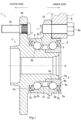
FIG. 1 is a cross-sectional view illustrating a bearing device for a vehicle wheel. -
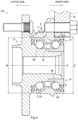
FIG. 2 is a cross-sectional view illustrating a bearing device for a vehicle wheel according to a first embodiment. -
FIG. 3 is a cross-sectional view illustrating a bearing device for a vehicle wheel according to a second embodiment. -
FIG. 4 is a cross-sectional view illustrating a bearing device for a vehicle wheel according to a third embodiment. -
FIG. 5 is a cross-sectional view illustrating a bearing device for a vehicle wheel according to a fourth embodiment. -
FIG. 6 is a cross-sectional view illustrating the bearing device for a vehicle wheel according to the first embodiment, and a partially enlarged cross-sectional view illustrating an inner-side induction-hardened part and a pocket on the inner-side. -
FIG. 7 is a front view illustrating a vehicle body mounting flange. - The overall configuration of a bearing device for a vehicle wheel 1 will be described with reference to
FIG. 1 . In the following description, "inner-side" represents the vehicle body side of the bearing device for a vehicle wheel 1 attached to a vehicle body, and "outer-side" represents the vehicle wheel side of the bearing device for a vehicle wheel 1 attached to the vehicle body. "Axial direction" represents the direction along a rotation axis A of the bearing device for a vehicle wheel 1. "Radial direction" represents the direction orthogonal to the rotation axis A of the bearing device for a vehicle wheel 1. "Circumferential direction" represents the direction along an arc centered on the rotation axis A of the bearing device for a vehicle wheel 1. "Axially outer side" represents the direction away from an annular space S along the rotation axis A, and "axially inner side" represents the direction to approach the annular space S along the rotation axis A. - As illustrated in
FIG. 1 , the bearing device for a vehicle wheel 1 supports a vehicle wheel to rotate in a suspension device of a vehicle such as a car. The bearing device for a vehicle wheel 1 includes anouter ring 2, ahub ring 3, aninner ring 4,rolling elements 5, an inner-side seal member 6, and an outer-side seal member 7. - The
outer ring 2, which is an outer member, supports thehub ring 3 and theinner ring 4. Aseal fitting portion 2b to which the inner-side seal member 6 is fitted is provided on an inner circumferential surface of an inner-side end 2a of theouter ring 2. Aseal fitting portion 2d to which the outer-side seal member 7 is fitted is provided on an inner circumferential surface of an outer-side end 2c of theouter ring 2. A vehiclebody mounting flange 2f is integrally provided on an outercircumferential surface 2e of theouter ring 2. Afixing bolt 8a for fastening together theouter ring 2 and aknuckle 8 is inserted in the vehiclebody mounting flange 2f. On the inner circumferential surface of theouter ring 2, a double-row ofouter raceway surfaces - An inner member includes the
hub ring 3 and theinner ring 4. Thehub ring 3 supports a vehicle wheel to rotate (not illustrated). A radially reduced small-diameterstepped portion 3a extending in the axial direction is provided at an inner-side end of the outer circumferential surface of thehub ring 3. On an outer-side end of thehub ring 3, a vehiclewheel mounting flange 3b for mounting a vehicle wheel is integrally provided. Ahub bolt 3c for fastening thehub ring 3 to a vehicle wheel or a braking device is press-fitted in the vehiclewheel mounting flange 3b. Alternatively, a tapped hole for fastening a hub bolt may be provided in the vehiclewheel mounting flange 3b. On the outer circumferential surface on the outer-side of thehub ring 3, aninner raceway surface 3d facing theouter raceway surface 2h on the outer-side is provided. That is, on the outer-side of the inner member, thehub ring 3 forms theinner raceway surface 3d. A slidingsurface 3e against which the outer-side seal member 7 slides is provided on the proximal side of the vehiclewheel mounting flange 3b of thehub ring 3. - The
inner ring 4 is press-fitted onto the small-diameterstepped portion 3a of thehub ring 3. Theinner ring 4 applies a pre-load to therolling elements 5. On the outer circumferential surface of theinner ring 4, aninner raceway surface 4a facing theouter raceway surface 2g on the inner-side is provided. That is, on the inner-side of the inner member, theinner ring 4 forms theinner raceway surface 4a. Aseal fitting portion 4b to which the inner-side seal member 6 is fitted is provided on the outer circumferential surface of an inner-side end 4c of theinner ring 4. - The
rolling elements 5 are balls. Therolling elements 5 on the inner-side and therolling elements 5 on the outer-side are held bycages 51. The rollingelements 5 on the inner-side are held between theinner raceway surface 4a of theinner ring 4 and theouter raceway surface 2g on the inner-side of theouter ring 2 so as to roll. The rollingelements 5 on the outer-side are held between theinner raceway surface 3d of thehub ring 3 and theouter raceway surface 2h on the outer-side of theouter ring 2 so as to roll. That is, the rollingelements 5 on the inner-side and the rollingelements 5 on the outer-side are held between the raceway surfaces of the outer member and the inner member so as to roll. As described above, in the bearing device for a vehicle wheel 1, theouter ring 2, thehub ring 3, theinner ring 4, and the double-row of rollingelements 5 constitute a double-row angular ball bearing. The bearing device for a vehicle wheel 1 may constitute a double-row tapered roller bearing instead of the double-row angular ball bearing. - The inner-
side seal member 6 and the outer-side seal member 7, which are seal members, are each a sealing member that closes an open end of the annular space S formed by the outer member and the inner member. The inner-side seal member 6 is attached to an inner-side open end formed between theouter ring 2 and theinner ring 4 of the annular space S. The outer-side seal member 7 is attached to an outer-side open end formed between theouter ring 2 and thehub ring 3 of the annular space S. - Next, features and effects of the bearing device for a vehicle wheel 1 according to a first embodiment will be described with reference to
FIG. 2 . - The
outer ring 2 is made of medium-carbon steel or high-carbon steel containing 0.40 to 0.80 wt% of carbon such as S53C. Theouter ring 2 is subjected to induction hardening along theouter raceway surfaces hardened part 9 is formed in theouter ring 2 as a result of the heat treatment step, thereby improving surface hardness and strength. - As illustrated in
FIG. 2 , the induction-hardened part 9 includes an inner-side induction-hardened part 9a that has been subjected to induction hardening along theouter raceway surface 2g on the inner-side, and an outer-side induction-hardened part 9b that has been subjected to induction hardening along theouter raceway surface 2h on the outer-side. A hardened layer depth D of the outer-side induction-hardened part 9b is deeper than a hardened layer depth E of the inner-side induction-hardened part 9a. The hardened layer depth D of the outer-side induction-hardened part 9b and the hardened layer depth E of the inner-side induction-hardened part 9a each indicate a hardened layer depth at an angle θ of 30 to 45 degrees with respect to the rotation axis A. In the drawing, the angle θ with respect to the rotation axis A on the inner-side is an angle to one side and the angle θ with respect to the rotation axis A on the outer-side is an angle to the other side. The induction-hardened part 9 has a surface hardness of 58 to 64 HRC. The hardened layer depth of the induction-hardened part 9 is the depth of a portion having a hardness of 78% or more of the surface hardness of the induction-hardened part 9. For example, the hardened layer depth D of the outer-side induction-hardened part 9b is 0.5 to 2.2 mm deeper than the hardened layer depth E of the inner-side induction-hardened part 9a at the same angle in axial cross sections of the same rotational phase (circumferential position) under the same definition of the hardened layer depth. - The inner-side induction-
hardened part 9a is formed along the entireouter raceway surface 2g on the inner-side. The outer-side induction-hardened part 9b is formed along the entireouter raceway surface 2h on the outer-side. Regarding the hardened layer depth in a direction normal to theouter raceway surface 2h of the outer-side induction-hardened part 9b, the hardened layer depth in the axially inner side (inner-side) of the outer-side hardened layer depth D is deeper than the hardened layer depth in the axially outer side (outer-side) of the outer-side hardened layer depth D. The outer-side induction-hardened part 9b and the inner-side induction-hardened part 9a are separated from each other. - According to the bearing device for a vehicle wheel 1 configured as described above, when a vehicle is large with respect to a bearing size or under a vehicle use condition with poor roadway infrastructure, happening of indentation defects in a market can be reduced by increasing only the hardened layer depth D of the outer-side induction-
hardened part 9b of theouter ring 2 where a large indentation may in particular occur. Increasing the hardened layer depth by induction hardening may cause a quenching crack or reduction in bearing life due to deterioration in crystal grain size caused by overheating. But a quenching crack and reduction in bearing life due to deterioration in crystal grain size in the inner-side of theouter ring 2 can be avoided by not increasing the hardened layer depth E of the inner-side induction-hardened part 9a on the inner-side of theouter ring 2 where improvement in indentation resistance is not necessary. In addition, since the inner-side induction-hardened part 9a and the outer-side induction-hardened part 9b are separated from each other, reduction in bearing life due to deterioration in crystal grain size in a portion between the inner-side induction-hardened part 9a and the outer-side induction-hardened part 9b can be suppressed. That is, the indentation resistance at the outer-side of theouter ring 2 can be improved while minimizing a quenching crack and deterioration in crystal grain size. - Next, features and effects of a bearing device for a
vehicle wheel 1A according to a second embodiment will be described with reference toFIG. 3 . Here, only portions different from those of the bearing device for a vehicle wheel 1 according to the first embodiment will be described. - The inner-side of the
outer ring 2 has a low degree of freedom in changing an outside diameter C, since fitting with a peripheral component (knuckle 8) needs to be considered. Meanwhile, the outer-side of theouter ring 2 has a high degree of freedom in changing an outside diameter B, since fitting with theknuckle 8 needs not be considered. Thus, the outer-side outside diameter B can be set larger than the inner-side outside diameter C, and theouter ring 2 is formed to have the outer-side outside diameter B larger than the inner-side outside diameter C. - According to the bearing device for a
vehicle wheel 1A configured as described above, increasing the thickness in the outer-side of theouter ring 2 can avoid a quenching crack due to insufficient thickness resulting from increasing the hardened layer depth D of the outer-side induction-hardened part 9b. In addition, since increasing the outer-side thickness of theouter ring 2 enhances the rigidity of the outer-side of theouter ring 2, deterioration in roundness of theouter raceway surface 2h due to loading is reduced. This increases the steel ball load factor of the outer-side of theouter ring 2 and improves indentation resistance. - Next, features and effects of a bearing device for a
vehicle wheel 1B according to a third embodiment will be described with reference toFIG. 4 . Here, only portions different from those of the bearing device for a vehicle wheel 1 according to the first embodiment will be described. - The inner-side induction-
hardened part 9a and the outer-side induction-hardened part 9b join at the radially inner side to be integrated. In theouter ring 2, the induction-hardened part 9 is formed entirely on the innercircumferential surface 2j between theouter raceway surface 2g on the inner-side and theouter raceway surface 2h on the outer-side. - According to the bearing device for a
vehicle wheel 1B configured as described above, a portion of the induction-hardened part 9 between the outer-sideouter raceway surface 2h and the inner-sideouter raceway surface 2g is formed in a wider area.
Thus, the indentation resistance of an axially inner side (inner-side) portion of the outer-sideouter raceway surface 2h can be improved. - Next, features and effects of a bearing device for a
vehicle wheel 1C according to a fourth embodiment will be described with reference toFIG. 5 . Here, only portions different from those of the bearing device for a vehicle wheel 1 according to the third embodiment will be described. - The inner-side of the
outer ring 2 has a low degree of freedom in changing an outside diameter C, since fitting with a peripheral component (knuckle 8) needs to be considered. Meanwhile, the outer-side of theouter ring 2 has a high degree of freedom in changing an outside diameter B, since fitting with theknuckle 8 needs not be considered. Thus, the outer-side outside diameter B can be set larger than the inner-side outside diameter C, and theouter ring 2 is formed to have the outer-side outside diameter B larger than the inner-side outside diameter C. - According to the bearing device for a
vehicle wheel 1C configured as described above, increasing the thickness of the outer-side of theouter ring 2 can avoid a quenching crack due to insufficient thickness resulting from increasing the hardened layer depth D of the outer-side induction-hardened part 9b. In addition, since increasing the outer-side thickness of theouter ring 2 enhances the rigidity of the outer-side of theouter ring 2, deterioration in roundness of theouter raceway surface 2h due to loading is reduced. This increases the steel ball load factor of the outer-side of theouter ring 2 and improves indentation resistance. - Next, other features and effects of the bearing devices for a
vehicle wheel FIGS. 6 and7 . - As illustrated in
FIG. 6 , theouter ring 2 has apocket 2k on each of the outer-side (axially inner side) of the sealfitting portion 2b and the inner-side (axially inner side) of the sealfitting portion 2d. Thepocket 2k is formed in a concave curved surface (rounded shape) in a cross-sectional view. In theouter ring 2, an inner-side end 9c of the inner-side induction-hardened part 9a is on the radially inner side of the inner-side pocket 2k, and an outer-side end 9d of the outer-side induction-hardened part 9b is on the radially inner side of the outer-side pocket 2k. For example, the inner-side pocket 2k has an inside diameter G at its radially inner end. The inner-side induction-hardened part 9a has an outside diameter F at the inner-side end 9c thereof. The outside diameter F of the inner-side induction-hardened part 9a is smaller than the inside diameter G of thepocket 2k. - According to the bearing devices for a
vehicle wheel hardened part 9 is not formed in thepocket 2k. When the boundary between the induction-hardened part 9 and the portion where no induction-hardened part 9 is formed is formed in thepocket 2k, tensile stress concentration may occur at the boundary. Forming thepocket 2k as described above prevents stress concentration at the boundary. Thus, degrading of the durability of thepocket 2k can be prevented. - Since the surface hardness of the rolling
elements 5 is higher than the surface hardness of theouter raceway surfaces vehicle wheel outer raceway surfaces vehicle wheel outer ring 2 can be improved as described above. That is, the indentation resistance of theouter raceway surface 2h can be improved. - As illustrated in
FIG. 7 , for example, theouter ring 2 has a vehiclebody mounting flange 2f at the upper end on the side opposite the road. When an excessive radial load is applied to the bearing device for avehicle wheel body mounting flange 2f, the moment from the vehiclewheel mounting flange 3b is readily transmitted to the upper portion of the outer-sideouter raceway surface 2h, which may readily create an indentation on theouter raceway surface 2h. However, according to the bearing devices for avehicle wheel outer ring 2 can be improved as described above. That is, the indentation resistance of theouter raceway surface 2h can be improved. - The bearing devices for a
vehicle wheel inner raceway surface 3d for therolling elements 5 is directly formed on the outer circumference of thehub ring 3. However, the embodiment is not limited to this configuration, and may have, for example, a second generation structure of rotating inner ring in which a pair ofinner rings 4 is press-fitted and fixed to thehub ring 3. Furthermore, the bearing device for a vehicle wheel may be a third generation structure or a second generation structure of rotating outer ring. In addition, the above embodiments each merely illustrate a representative mode of the present invention, and various modifications can be made without departing from the gist of the present invention. - The present invention is applicable to a bearing device for a vehicle wheel.
-
- 1
- bearing device for a vehicle wheel
- 1A
- bearing device for a vehicle wheel
- 1B
- bearing device for a vehicle wheel
- 1C
- bearing device for a vehicle wheel
- 2
- outer ring (outer member)
- 2b
- seal fitting portion
- 2d
- seal fitting portion
- 2g
- outer raceway surface
- 2h
- outer raceway surface
- 2k
- 3
- hub ring (inner member)
- 3d
- inner raceway surface
- 4
- inner ring (inner member)
- 4a
- inner raceway surface
- 5
- rolling element
- 6
- inner-side seal member
- 7
- outer-side seal member
- 9
- induction-hardened part
- 9a
- inner-side induction-hardened part
- 9b
- outer-side induction-hardened part
- 9c
- inner-side end of inner-side induction-hardened part
- 9d
- outer-side end of outer-side induction-hardened part
- B
- outer-side outside diameter of outer member
- C
- inner-side outside diameter of outer member
- D
- outer-side hardened layer depth
- E
- inner-side hardened layer depth
- θ
- angle
Claims (7)
- A bearing device for a vehicle wheel, the bearing device comprising:an outer member having a double-row of outer raceway surfaces on an inner circumference;an inner member having a double-row of inner raceway surfaces facing the double-row of outer raceway surfaces; anda double-row of rolling elements rollably held between the outer raceway surfaces of the outer member and the inner raceway surfaces of the inner member, whereinthe outer member has an inner-side induction-hardened part formed by induction hardening along the outer raceway surface on an inner-side, and an outer-side induction-hardened part formed by induction hardening along the outer raceway surface on an outer-side,a hardened layer depth of the outer-side induction-hardened part is deeper than a hardened layer depth of the inner-side induction-hardened part, andthe inner-side induction-hardened part and the outer-side induction-hardened part are separated from each other.
- The bearing device for a vehicle wheel according to claim 1, wherein an outer-side outside diameter of the outer member is larger than an inner-side outside diameter of the outer member.
- A bearing device for a vehicle wheel, the bearing device comprising:an outer member having a double-row of outer raceway surfaces on an inner circumference;an inner member having a double-row of inner raceway surfaces facing the double-row of outer raceway surfaces; anda double-row of rolling elements rollably held between the outer raceway surfaces of the outer member and the inner raceway surfaces of the inner member, whereinthe outer member has an inner-side induction-hardened part formed by induction hardening along the outer raceway surface on an inner-side, and an outer-side induction-hardened part formed by induction hardening along the outer raceway surface on an outer-side,a hardened layer depth of the outer-side induction-hardened part is deeper than a hardened layer depth of the inner-side induction-hardened part, andthe inner-side induction-hardened part and the outer-side induction-hardened part are joined.
- The bearing device for a vehicle wheel according to claim 3, wherein an outer-side outside diameter of the outer member is larger than an inner-side outside diameter of the outer member.
- The bearing device for a vehicle wheel according to any one of claims 1 to 4, further comprisinga seal member that closes an open end of an annular space formed by the outer member and the inner member, whereinthe outer member includes a seal fitting portion to which the seal member is fitted, and a pocket is provided on an axially inner side of the seal fitting portion, andan inner-side end of the inner-side induction-hardened part is located on a radially inner side of the pocket on the inner-side, and an outer-side end of the outer-side induction-hardened part is located on a radially inner side of the pocket on the outer-side.
- The bearing device for a vehicle wheel according to any one of claims 1 to 5, wherein in a region within a range where an angle with respect to a rotation axis of the bearing device for a vehicle wheel is from 30 to 45 degrees, the hardened layer depth of the outer-side induction-hardened part is deeper than the hardened layer depth of the inner-side induction-hardened part.
- The bearing device for a vehicle wheel according to any one of claims 1 to 6, wherein surface hardness of the rolling elements is higher than surface hardness of the double-row of outer raceway surfaces.
Applications Claiming Priority (2)
| Application Number | Priority Date | Filing Date | Title |
|---|---|---|---|
| JP2022005839A JP2023104692A (en) | 2022-01-18 | 2022-01-18 | Wheel bearing device |
| PCT/JP2022/046437 WO2023139994A1 (en) | 2022-01-18 | 2022-12-16 | Wheel bearing device |
Publications (2)
| Publication Number | Publication Date |
|---|---|
| EP4467670A1 true EP4467670A1 (en) | 2024-11-27 |
| EP4467670A4 EP4467670A4 (en) | 2025-05-14 |
Family
ID=87348076
Family Applications (1)
| Application Number | Title | Priority Date | Filing Date |
|---|---|---|---|
| EP22922145.2A Pending EP4467670A4 (en) | 2022-01-18 | 2022-12-16 | WHEEL BEARING DEVICE |
Country Status (5)
| Country | Link |
|---|---|
| US (1) | US20250129817A1 (en) |
| EP (1) | EP4467670A4 (en) |
| JP (1) | JP2023104692A (en) |
| CN (1) | CN118525155A (en) |
| WO (1) | WO2023139994A1 (en) |
Family Cites Families (7)
| Publication number | Priority date | Publication date | Assignee | Title |
|---|---|---|---|---|
| US6287009B1 (en) * | 1998-03-06 | 2001-09-11 | Nsk Ltd. | Rolling bearing unit with rotation speed detection instrument for use in cars and method for working outer race for use in this bearing unit |
| JP2000211310A (en) * | 1999-01-21 | 2000-08-02 | Ntn Corp | Wheel support structure |
| JP2007332998A (en) | 2006-06-12 | 2007-12-27 | Nsk Ltd | Outer ring member of wheel bearing unit and wheel bearing unit using the same |
| JP5641706B2 (en) * | 2009-04-02 | 2014-12-17 | Ntn株式会社 | Wheel bearing device |
| JP2014077527A (en) * | 2012-10-12 | 2014-05-01 | Ntn Corp | Wheel bearing device and manufacturing method thereof |
| JP2014142054A (en) * | 2012-12-26 | 2014-08-07 | Nsk Ltd | Wheel support rolling bearing unit |
| JP2017082824A (en) * | 2015-10-23 | 2017-05-18 | 日本精工株式会社 | Manufacturing method of outer ring of rolling bearing unit for wheel support |
-
2022
- 2022-01-18 JP JP2022005839A patent/JP2023104692A/en active Pending
- 2022-12-16 EP EP22922145.2A patent/EP4467670A4/en active Pending
- 2022-12-16 WO PCT/JP2022/046437 patent/WO2023139994A1/en not_active Ceased
- 2022-12-16 CN CN202280088628.4A patent/CN118525155A/en active Pending
- 2022-12-16 US US18/726,268 patent/US20250129817A1/en active Pending
Also Published As
| Publication number | Publication date |
|---|---|
| WO2023139994A1 (en) | 2023-07-27 |
| CN118525155A (en) | 2024-08-20 |
| US20250129817A1 (en) | 2025-04-24 |
| EP4467670A4 (en) | 2025-05-14 |
| JP2023104692A (en) | 2023-07-28 |
Similar Documents
| Publication | Publication Date | Title |
|---|---|---|
| US7862242B2 (en) | Wheel bearing apparatus for a vehicle | |
| US7648284B2 (en) | Bearing apparatus for a wheel of vehicle | |
| JP2002087008A (en) | Wheel bearing system | |
| JP2008100632A (en) | Bearing device for wheel | |
| JP4150317B2 (en) | Wheel bearing device | |
| JP2006137297A (en) | Bearing device for wheel | |
| JP2008284960A (en) | Wheel bearing system | |
| US20250129817A1 (en) | Bearing device for vehicle wheel | |
| JP2005349928A (en) | Bearing device for wheel | |
| JP2011005963A (en) | Bearing device for wheel | |
| JP4844967B2 (en) | Wheel bearing device | |
| CN101297125B (en) | Bearing device for wheel | |
| JP2008296621A (en) | Wheel bearing device | |
| JP2006046401A (en) | Bearing device for wheel | |
| JP5236097B2 (en) | Wheel bearing device | |
| JP5024850B2 (en) | Wheel bearing device | |
| JP4969899B2 (en) | Wheel bearing device | |
| CN101432540B (en) | Bearing device for wheel | |
| JP2007024208A (en) | Bearing device for wheel | |
| JP2005075135A (en) | Bearing device for vehicle | |
| JP2023117989A (en) | Wheel bearing device | |
| JP4034799B2 (en) | Wheel bearing device | |
| JP5736025B2 (en) | Wheel bearing device | |
| JP4986277B2 (en) | Wheel bearing device | |
| JP2011106531A (en) | Bearing device for wheel |
Legal Events
| Date | Code | Title | Description |
|---|---|---|---|
| STAA | Information on the status of an ep patent application or granted ep patent |
Free format text: STATUS: THE INTERNATIONAL PUBLICATION HAS BEEN MADE |
|
| PUAI | Public reference made under article 153(3) epc to a published international application that has entered the european phase |
Free format text: ORIGINAL CODE: 0009012 |
|
| STAA | Information on the status of an ep patent application or granted ep patent |
Free format text: STATUS: REQUEST FOR EXAMINATION WAS MADE |
|
| 17P | Request for examination filed |
Effective date: 20240806 |
|
| AK | Designated contracting states |
Kind code of ref document: A1 Designated state(s): AL AT BE BG CH CY CZ DE DK EE ES FI FR GB GR HR HU IE IS IT LI LT LU LV MC ME MK MT NL NO PL PT RO RS SE SI SK SM TR |
|
| DAV | Request for validation of the european patent (deleted) | ||
| DAX | Request for extension of the european patent (deleted) | ||
| A4 | Supplementary search report drawn up and despatched |
Effective date: 20250414 |
|
| RIC1 | Information provided on ipc code assigned before grant |
Ipc: B60B 35/02 20060101ALI20250408BHEP Ipc: F16C 33/64 20060101ALI20250408BHEP Ipc: F16C 33/58 20060101ALI20250408BHEP Ipc: F16C 19/18 20060101ALI20250408BHEP Ipc: C21D 9/40 20060101AFI20250408BHEP |
|
| STAA | Information on the status of an ep patent application or granted ep patent |
Free format text: STATUS: EXAMINATION IS IN PROGRESS |
|
| 17Q | First examination report despatched |
Effective date: 20251016 |
|
| GRAP | Despatch of communication of intention to grant a patent |
Free format text: ORIGINAL CODE: EPIDOSNIGR1 |
|
| STAA | Information on the status of an ep patent application or granted ep patent |
Free format text: STATUS: GRANT OF PATENT IS INTENDED |