EP4467499A1 - Spinning take-up device - Google Patents
Spinning take-up device Download PDFInfo
- Publication number
- EP4467499A1 EP4467499A1 EP24174048.9A EP24174048A EP4467499A1 EP 4467499 A1 EP4467499 A1 EP 4467499A1 EP 24174048 A EP24174048 A EP 24174048A EP 4467499 A1 EP4467499 A1 EP 4467499A1
- Authority
- EP
- European Patent Office
- Prior art keywords
- yarn
- speed
- fulcrum guide
- guide
- rotation speed
- Prior art date
- Legal status (The legal status is an assumption and is not a legal conclusion. Google has not performed a legal analysis and makes no representation as to the accuracy of the status listed.)
- Granted
Links
Images


Classifications
-
- B—PERFORMING OPERATIONS; TRANSPORTING
- B65—CONVEYING; PACKING; STORING; HANDLING THIN OR FILAMENTARY MATERIAL
- B65H—HANDLING THIN OR FILAMENTARY MATERIAL, e.g. SHEETS, WEBS, CABLES
- B65H57/00—Guides for filamentary materials; Supports therefor
- B65H57/14—Pulleys, rollers, or rotary bars
-
- D—TEXTILES; PAPER
- D01—NATURAL OR MAN-MADE THREADS OR FIBRES; SPINNING
- D01D—MECHANICAL METHODS OR APPARATUS IN THE MANUFACTURE OF ARTIFICIAL FILAMENTS, THREADS, FIBRES, BRISTLES OR RIBBONS
- D01D10/00—Physical treatment of artificial filaments or the like during manufacture, i.e. during a continuous production process before the filaments have been collected
- D01D10/04—Supporting filaments or the like during their treatment
- D01D10/0436—Supporting filaments or the like during their treatment while in continuous movement
-
- B—PERFORMING OPERATIONS; TRANSPORTING
- B65—CONVEYING; PACKING; STORING; HANDLING THIN OR FILAMENTARY MATERIAL
- B65H—HANDLING THIN OR FILAMENTARY MATERIAL, e.g. SHEETS, WEBS, CABLES
- B65H57/00—Guides for filamentary materials; Supports therefor
- B65H57/003—Arrangements for threading or unthreading the guide
-
- B—PERFORMING OPERATIONS; TRANSPORTING
- B65—CONVEYING; PACKING; STORING; HANDLING THIN OR FILAMENTARY MATERIAL
- B65H—HANDLING THIN OR FILAMENTARY MATERIAL, e.g. SHEETS, WEBS, CABLES
- B65H57/00—Guides for filamentary materials; Supports therefor
- B65H57/16—Guides for filamentary materials; Supports therefor formed to maintain a plurality of filaments in spaced relation
-
- B—PERFORMING OPERATIONS; TRANSPORTING
- B65—CONVEYING; PACKING; STORING; HANDLING THIN OR FILAMENTARY MATERIAL
- B65H—HANDLING THIN OR FILAMENTARY MATERIAL, e.g. SHEETS, WEBS, CABLES
- B65H57/00—Guides for filamentary materials; Supports therefor
- B65H57/26—Supports for guides
-
- B—PERFORMING OPERATIONS; TRANSPORTING
- B65—CONVEYING; PACKING; STORING; HANDLING THIN OR FILAMENTARY MATERIAL
- B65H—HANDLING THIN OR FILAMENTARY MATERIAL, e.g. SHEETS, WEBS, CABLES
- B65H67/00—Replacing or removing cores, receptacles, or completed packages at paying-out, winding, or depositing stations
- B65H67/04—Arrangements for removing completed take-up packages and or replacing by cores, formers, or empty receptacles at winding or depositing stations; Transferring material between adjacent full and empty take-up elements
- B65H67/044—Continuous winding apparatus for winding on two or more winding heads in succession
- B65H67/048—Continuous winding apparatus for winding on two or more winding heads in succession having winding heads arranged on rotary capstan head
-
- D—TEXTILES; PAPER
- D01—NATURAL OR MAN-MADE THREADS OR FIBRES; SPINNING
- D01D—MECHANICAL METHODS OR APPARATUS IN THE MANUFACTURE OF ARTIFICIAL FILAMENTS, THREADS, FIBRES, BRISTLES OR RIBBONS
- D01D10/00—Physical treatment of artificial filaments or the like during manufacture, i.e. during a continuous production process before the filaments have been collected
- D01D10/04—Supporting filaments or the like during their treatment
- D01D10/0436—Supporting filaments or the like during their treatment while in continuous movement
- D01D10/0454—Supporting filaments or the like during their treatment while in continuous movement using reels
-
- B—PERFORMING OPERATIONS; TRANSPORTING
- B65—CONVEYING; PACKING; STORING; HANDLING THIN OR FILAMENTARY MATERIAL
- B65H—HANDLING THIN OR FILAMENTARY MATERIAL, e.g. SHEETS, WEBS, CABLES
- B65H2701/00—Handled material; Storage means
- B65H2701/30—Handled filamentary material
- B65H2701/31—Textiles threads or artificial strands of filaments
- B65H2701/313—Synthetic polymer threads
- B65H2701/3132—Synthetic polymer threads extruded from spinnerets
Definitions
- the present invention relates to a spinning take-up device including a guide body having a fulcrum guide serving as a fulcrum when winding a yarn around a bobbin while traversing the yarn.
- a spinning take-up device that winds a yarn spun from a spinning device around a bobbin while traversing the yarn.
- a spinning take-up device is provided with a fulcrum guide serving as a supporting point when traversing the yarn.
- a cylindrical fulcrum guide is provided, and the yarn is threaded on an outer peripheral surface of the fulcrum guide.
- the fulcrum guide of JP 2022-112481 A is configured to rotate at a peripheral speed slower than the travelling speed of the yarn when the fulcrum guide receives a torque of a predetermined value or more from the travelling yarn.
- an object of the present application is to reduce local wear of the fulcrum guide and to suppress early breakage of the fulcrum guide.
- a spinning take-up device of the present invention is a spinning take-up device configured to wind a plurality of yarns fed by a yarn feeding roller around a plurality of bobbins attached to a bobbin holder, the spinning take-up device including: a guide body including a fulcrum guide serving as a fulcrum when winding the yarn around the bobbin attached to the bobbin holder while traversing the yarn, the guide body being arranged between the yarn feeding roller and the bobbin holder in a yarn travelling direction in which the yarn travels; a first switching control unit configured to switch a rotation speed of the yarn feeding roller between a first yarn winding speed when winding the yarn around the bobbin and a first yarn threading speed lower than the first yarn winding speed and when threading the yarn around the bobbin; and a second switching control unit configured to switch a rotation speed of the bobbin holder between a second yarn winding speed when winding the yarn around the bobbin and a second yarn threading speed lower than the second yarn
- the inventors of the present application have intensively investigated the cause of the problem that the fulcrum guide is damaged early, and as a result, have estimated that the rotation speed of the fulcrum guide in the acceleration period may be excessively larger than the rotation speed of the fulcrum guide in the constant speed period, a large torque is applied to the fulcrum guide in the acceleration period, and the load on the bearing becomes very large. Then, the inventors have found that when the rotation speed of the fulcrum guide becomes about 14000 rpm or more, the fulcrum guide is damaged and wear of the bearing becomes severe.
- the spinning take-up device of the present invention further preferably includes: a contact roller configured to make contact with outer peripheral surfaces of the plurality of bobbins attached to the bobbin holder; and a third switching control unit configured to switch a rotation speed of the contact roller between a third yarn winding speed when winding the yarn around the bobbin and a third yarn threading speed lower than the third yarn winding speed and when threading the yarn around the bobbin, in which, in the acceleration period, a rotation speed of the contact roller is preferably accelerated from the third yarn threading speed to the third yarn winding speed, and in which, in the constant speed period, the rotation speed of the contact roller is preferably the third yarn winding speed.
- the present invention in the configuration in which the rotation speed of the contact roller is accelerated during the acceleration period, it is possible to effectively suppress early breakage of the fulcrum guide.
- the rotational resistance applying means preferably applies rotational resistance to the fulcrum guide so that a maximum rotation speed of the fulcrum guide in the acceleration period is 12000 rpm or less.
- the rotational resistance applying means preferably includes: a pressed portion arranged on one side in an axial direction of the fulcrum guide; and a pressing member that presses the fulcrum guide toward the pressed portion, and in which an interposed member is arranged between the fulcrum guide and the pressed portion and/or between the fulcrum guide and the pressing member.
- the rotational resistance can be applied to the fulcrum guide by the pressing force of the pressing member.
- the pressing force acting on the fulcrum guide can be adjusted by the shape, size, material, and the like of the interposed members, and the rotation speed and peripheral speed of the fulcrum guide can be easily adjusted.
- the interposed member is preferably made of PEEK-based resin.
- the PEEK-based resin excellent in slidability and heat resistance is used as the interposed member, it is possible to suppress wear and deterioration of the interposed member in direct contact with the rotating fulcrum guide.
- a dispersion member for dispersing a force from the pressing member toward the interposed member is preferably arranged between the pressing member and the interposed member.
- the present invention it is possible to suppress application of a force locally from the pressing member to the interposed member and to suppress early damage of the interposed member.
- the fulcrum guide is preferably made of ceramic.
- the yarn in contact with the fulcrum guide can be suppressed from being worn by friction as compared with the case of using a fulcrum guide of another material.
- the ceramic fulcrum guide has a property of being easily damaged. In such a configuration using the ceramic fulcrum guide which is easily damaged, the damage of the fulcrum guide can be more effectively suppressed by applying the present invention.
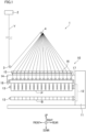
- FIG. 1 is a side view of a spinning take-up device 1 according to the present embodiment.
- front, back, left, right, up, and down directions illustrated in FIG. 1 are defined as front, back, left, right, up, and down directions of the spinning take-up device 1.
- the spinning take-up device 1 is a device configured to receive a plurality of (16 in the present embodiment) yarns Y spun from a spinning device 2, and includes godet rollers 3 and 4 (yarn feeding roller of the present invention) and a yarn winding device 10.
- the spinning device 2 is arranged above the spinning take-up device 1, and spins the plurality of yarns Y made of synthetic resin.
- the godet rollers 3 and 4 are arranged below the spinning device 2, and are rotationally driven by roller motors 51 and 52 (see FIG. 4 ) to be described later.
- the plurality of yarns Y spun from the spinning device 2 are fed to the yarn winding device 10 via the godet rollers 3 and 4.
- the yarn winding device 10 is arranged below the godet rollers 3 and 4.
- the yarn winding device 10 includes two bobbin holders 13 cantilevered by a turret 12 incorporated in a machine base 11.
- the bobbin holder 13 extends in the front-rear direction, and a rear end portion thereof is supported by the turret 12.
- a plurality of bobbins B can be attached to the bobbin holder 13 in the front-rear direction.
- the bobbin holder 13 is rotationally driven around the axis by a winding motor 53 (see FIG. 4 ) to be described later.
- the turret 12 is a disc-shaped member having a rotation axis parallel to the front-rear direction, and the bobbin holder 13 is attached to each of an upper position and a lower position different by 180 degrees in the circumferential direction.
- the two bobbin holders 13 are moved between the upper position and the lower position.
- the plurality of yarns Y are wound around the plurality of bobbins B to form a plurality of packages P.
- the plurality of packages P are collected and a plurality of new bobbins B are attached.
- the yarn winding device 10 includes a supporting frame 14 cantilevered by a machine base 11. A rear end portion of the supporting frame 14 is supported by the machine base 11. A guide unit 15 is arranged above the supporting frame 14. In the guide unit 15, guide bodies 16 of the same number as the number of the yarns Y are arranged in the front-rear direction. Traverse devices 17 of the same number as the number of the yarns Y are arranged in the front-rear direction on the supporting frame 14. The traverse device 17 traverses the yarn Y in the front-rear direction with the corresponding guide body 16 as a supporting point.
- a contact roller 18 rotatably supported by the supporting frame 14 is arranged below the supporting frame 14.
- the contact roller 18 makes contact with the outer peripheral surfaces of the plurality of bobbins B attached to the bobbin holder 13 at the upper position or the outer peripheral surfaces of the plurality of packages P formed by winding the yarns Y around the plurality of bobbins B.
- the contact roller 18 rotates while applying a predetermined contact pressure to the package P, so that the shape of the package P can be adjusted.
- the contact roller 18 is rotationally driven by a CR motor 54 (see FIG. 4 ) to be described later.
- FIG. 4 is a block diagram illustrating an electrical configuration of the spinning take-up device 1.
- the spinning take-up device 1 includes a controller 60.
- the controller 60 is electrically connected to the roller motor 51, a roller motor 52, the winding motor 53, and the CR motor 54.
- the controller 60 controls the roller motor 51 to switch the rotation speed of the godet roller 3 between a first yarn winding speed and a first yarn threading speed.
- the first yarn winding speed of the godet roller 3 is the rotation speed of the godet roller 3 when winding the yarn Y around the bobbin B by the yarn winding device 10.
- the first yarn threading speed of the godet roller 3 is lower than the first yarn winding speed, and is the rotation speed of the godet roller 3 when threading the yarn Y on the bobbin B.
- the controller 60 controls the roller motor 52 to switch the rotation speed of the godet roller 4 between the first yarn winding speed and the first yarn threading speed.
- the first yarn winding speed of the godet roller 4 is the rotation speed of the godet roller 4 when winding the yarn Y around the bobbin B by the yarn winding device 10.
- the first yarn threading speed of the godet roller 4 is lower than the first yarn winding speed, and is the rotation speed of the godet roller 4 when threading the yarn Y on the bobbin B.
- the controller 60 of the present embodiment corresponds to a first switching control unit of the present invention.
- the first yarn winding speed and the first yarn threading speed of the godet roller 3 may be different from or the same as the first yarn winding speed and the first yarn threading speed of the godet roller 4.
- the controller 60 controls the winding motor 53 to switch the rotation speed of the bobbin holder 13 between a second yarn winding speed and a second yarn threading speed.
- the second yarn winding speed is the rotation speed of the bobbin holder 13 when winding the yarn Y around the bobbin B by the yarn winding device 10.
- the second yarn threading speed is lower than the second yarn winding speed, and is the rotation speed of the bobbin holder 13 when threading the yarn Y on the bobbin B.
- the controller 60 of the present embodiment also corresponds to the second switching control unit of the present invention.
- the controller 60 controls the CR motor 54 to switch the rotation speed of the contact roller 18 between a third yarn winding speed and a third yarn threading speed.
- the third yarn winding speed is the rotation speed of the contact roller 18 when winding the yarn Y around the bobbin B by the yarn winding device 10.
- the third yarn threading speed is lower than the third yarn winding speed, and is the rotation speed of the contact roller 18 when threading the yarn Y on the bobbin B.
- the controller 60 of the present embodiment also corresponds to a third switching control unit of the present invention.
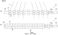
- FIGS. 2A and 2B are side views of the guide unit 15.
- FIG. 2A illustrates a state in which the plurality of guide bodies 16 are located at winding positions
- FIG. 2B illustrates a state in which the plurality of guide bodies 16 are located at yarn threading positions.
- the winding positions are positions of the plurality of guide bodies 16 when winding the plurality of yarns Y around the plurality of bobbins B.
- the yarn threading positions are positions of the plurality of guide bodies 16 when threading the plurality of yarns Y on the plurality of guide bodies 16.
- the plurality of guide bodies 16 are configured to be movable between the winding positions and the yarn threading positions.
- the guide unit 15 includes the plurality of guide bodies 16, a plurality of sliders 21, a guide rail 22, and an air cylinder 23.
- the sliders 21 are provided as many as the number of guide bodies 16, and each guide body 16 is attached to the corresponding slider 21.
- the guide rail 22 is a member extending in the front-rear direction, and is fixed to the supporting frame 14 via a bracket (not illustrated).
- the plurality of sliders 21 are slidably attached to the guide rail 22 in a state of being arranged in the front-rear direction.
- the sliders 21 adjacent to each other are connected by a belt (not illustrated).
- the air cylinder 23 is a driving device for moving the plurality of guide bodies 16 between the winding positions and the yarn threading positions.
- a rod 23a of the air cylinder 23 is connected to the rearmost slider 21.
- the driving device that moves the plurality of guide bodies 16 is not limited to the air cylinder 23, and may be another actuator such as a motor.
- the plurality of sliders 21 are arranged in the front-rear direction in a state of being separated from each other.
- the positions of the plurality of guide bodies 16 at this time are the winding positions.
- the plurality of sliders 21 gather at the front end portion of the guide rail 22.
- the positions of the plurality of guide bodies 16 at this time are the yarn threading positions.
- the yarn paths of the plurality of yarns Y distributed from the godet roller 4 to the plurality of guide bodies 16 located at the winding positions are substantially symmetrical with respect to a vertical plane passing through the centers of the plurality of guide bodies 16 in the front-rear direction.
- the eight yarns Y on the front half are threaded on the front side of the guide body 16, whereas the eight yarns Y on the back half are threaded on the back side of the guide body 16.
- FIG. 3 is a cross-sectional view of the guide body 16.
- the guide body 16 includes a fulcrum guide 31, a fixing member 32, and a shaft member 33.
- the guide body 16 is arranged between the godet roller 4 and the bobbin holder 13 in the yarn travelling direction in which the yarn Y travels.
- the fulcrum guide 31 serves as a fulcrum when winding the yarn Y around the bobbin B attached to the bobbin holder 13 while traversing the yarn Y.
- the fulcrum guide 31 has a cylindrical shape extending in the left-right direction, and is supported by the shaft member 33 so as to be rotatable about the central axis.
- the yarn Y is threaded on the outer peripheral surface of the fulcrum guide 31, and travels while making contact with the outer peripheral surface of the fulcrum guide 31 at the time of yarn winding.
- the material of the fulcrum guide 31 is not limited, but is preferably ceramic, for example.
- the fixing member 32 has a cylindrical small-diameter portion 32a and a cylindrical large-diameter portion 32b.
- the small-diameter portion 32a is inserted into a circular attachment hole 21a formed in the slider 21.
- An annular concave portion 32c is formed at the right end portion of the large-diameter portion 32b.
- a spring 36 (pressing member of the present invention) is arranged in the concave portion 32c.
- a female screw portion 32d penetrating in the left-right direction is formed in the fixing member 32.
- the fixing member 32 is fixed to the slider 21 by a bolt (not illustrated) in a state where the small-diameter portion 32a is inserted from the right side of the attachment hole 21a and the flange surface of the large-diameter portion 32b abuts on the slider 21.
- the shaft member 33 is a member in which a shaft portion 33a and a flange portion 33b (pressed portion of the present invention) are integrally formed.
- the shaft portion 33a has a cylindrical shape extending in the left-right direction.
- the shaft portion 33a rotatably supports the fulcrum guide 31 externally fitted to the shaft portion 33a.
- the flange portion 33b is an annular portion expanding radially outward of the shaft portion 33a from a right end portion of the shaft portion 33a.
- the shaft member 33 is formed with a through hole 33c penetrating in the left-right direction.
- the right end portion of the through hole 33c has a larger inner diameter toward the right, and a tapered surface 33d on which the head of the bolt 39 abuts is formed.
- the interposed members 34 and 35 made of resin are arranged adjacent to the fulcrum guide 31 on both axial sides of the fulcrum guide 31.
- the interposed members 34 and 35 are annular members having an L-shaped cross section, and include thrust bearing portions 34a and 35a extending in the radial direction of the fulcrum guide 31 and radial bearing portions 34b and 35b extending in the axial direction of the fulcrum guide 31.
- thrust bearing portions 34a and 35a extending in the radial direction of the fulcrum guide 31 and radial bearing portions 34b and 35b extending in the axial direction of the fulcrum guide 31.
- PEEK-based resin is used for the interposed members 34 and 35.
- the thrust bearing portion 34a of the interposed member 34 on the right side is arranged between the fulcrum guide 31 and the flange portion 33b of the shaft member 33 in the axial direction of the fulcrum guide 31, and abuts on the right end surface of the fulcrum guide 31.
- the thrust bearing portion 35a of the interposed member 35 on the left side is arranged between the fulcrum guide 31 and the spring 36 via a dispersion ring 45 to be described later in the axial direction of the fulcrum guide 31, and abuts on the left end surface of the fulcrum guide 31.
- the radial bearing portions 34b and 35b are arranged between the fulcrum guide 31 and the shaft portion 33a of the shaft member 33 in the radial direction of the fulcrum guide 31, and abut on the inner peripheral surface of the fulcrum guide 31.
- the dispersion ring 45 (dispersion member of the present invention) is provided between the spring 36 and the thrust bearing portion 35a of the interposed member 35.
- the dispersion ring 45 is an annular member.
- the dispersion ring 45 is a member for dispersing a force from the spring 36 toward the interposed member 35.
- the dispersion ring 45 may be made of metal or resin, for example.
- the spinning take-up device 1 of the present embodiment takes a yarn threading period, an acceleration period, and a constant speed period as the controller 60 controls the driving of each motor.
- the yarn threading period is a period in which the yarn Y is threaded on the bobbin B attached to the bobbin holder 13 at the upper position.
- the rotation speed of the godet rollers 3 and 4 is the first yarn threading speed
- the rotation speed of the bobbin holder 13 is the second yarn threading speed
- the rotation speed of the contact roller 18 is the third yarn threading speed.
- the controller 60 controls the driving of each motor so that the rotation speed of the godet rollers 3 and 4 becomes a constant speed at the first yarn threading speed, the rotation speed of the bobbin holder 13 becomes a constant speed at the second yarn threading speed, and the rotation speed of the contact roller 18 becomes a constant speed at the third yarn threading speed.
- the acceleration period is a period when the rotation speed of the bobbin holder 13 is accelerated to the yarn winding speed after the yarn Y is threaded on the bobbin holder 13.
- the rotation speeds of the godet rollers 3 and 4 are accelerated from the first yarn threading speed to the first yarn winding speed
- the rotation speed of the bobbin holder 13 is accelerated from the second yarn threading speed to the second yarn winding speed
- the rotation speed of the contact roller 18 is accelerated from the third yarn threading speed to the third yarn winding speed.
- the controller 60 controls the driving of each motor so that the rotation speed of the godet rollers 3 and 4 is accelerated from the first yarn threading speed to the first yarn winding speed, the rotation speed of the bobbin holder 13 is accelerated from the second yarn threading speed to the second yarn winding speed, and the rotation speed of the contact roller 18 is accelerated from the third yarn threading speed to the third yarn winding speed.
- the constant speed period is a period in which the rotation speed of the bobbin holder 13 at the upper position is constant at the yarn winding speed.
- the rotation speed of the godet rollers 3 and 4 is the first yarn winding speed
- the rotation speed of the bobbin holder 13 is the second yarn winding speed
- the rotation speed of the contact roller 18 is the third yarn winding speed.
- the controller 60 controls the driving of each motor so that the rotation speed of the godet rollers 3 and 4 becomes a constant speed at the first yarn winding speed
- the rotation speed of the bobbin holder 13 becomes a constant speed at the second yarn winding speed
- the rotation speed of the contact roller 18 becomes a constant speed at the third yarn winding speed.
- the maximum rotation speed of the fulcrum guide 31 configured to rotate by making contact with the yarn Y in the acceleration period becomes greater than the maximum rotation speed of the fulcrum guide 31 in the constant speed period.
- the turret 12 When the spinning take-up device 1 transitions from the acceleration period to the constant speed period, the turret 12 first rotates to move the bobbin holder 13 to which the bobbin B around which the yarn Y is wound during the acceleration period is attached to the lower position, and move the bobbin holder 13 to which the empty bobbin B is attached to the upper position. Thereafter, the yarn Y is wound around the bobbin B attached to the bobbin holder 13 newly moved to the upper position to form the package P.
- FIG. 5 is a graph simultaneously showing the time dependency of a peripheral speed V1 and a tension T in order to know the relationship between the peripheral speed V1 [m/min] of the bobbin holder 13 and the tension T [cN] of the yarn Y threaded on the bobbin holder 13.
- the peripheral speed V1 [m/min] of the bobbin holder 13 and the tension T [cN] of the yarn Y illustrated in FIG. 5 are values when the spinning take-up device 1 of the present embodiment is used.
- the horizontal axis in FIG. 5 indicates the lapse of time [sec].
- the tension T of the yarn Y is a measured value of the tension T of the yarn Y travelling between the fulcrum guide 31 and the godet roller 4.
- the measured value of the tension T of the yarn Y is a value obtained when selecting one fulcrum guide 31 from the plurality of fulcrum guides 31 and measuring the tension T of the yarn Y travelling between the fulcrum guide 31 and the godet roller 4.
- the tension T of the yarn Y is assumed to exhibit a similar behavior regardless of which fulcrum guide 31 is selected.
- the peripheral speed V1 of the bobbin holder 13 has a constant speed period (0 sec to about 2 sec) at about 1700 m/min, an acceleration period (about 2 sec to about 37 sec) from about 1700 m/min to about 4300 m/min, and a constant speed period (about 37 sec to 50 sec) at about 4300 m/min.
- a yarn threading period (0 sec to about 2 sec)
- an acceleration period about 2 sec to about 37 sec
- a constant speed period about 37 sec to 50 sec
- the timing at which the peripheral speed V1 of the bobbin holder 13 fluctuates is the same as the timing at which the rotation speeds of the godet rollers 3 and 4 and the contact roller 18 fluctuate.
- the peripheral speed V1 of the bobbin holder 13 is illustrated to illustrate the yarn threading period, the acceleration period, and the constant speed period, and the description of the peripheral speeds (or the rotation speeds) of the godet rollers 3 and 4 and the contact roller 18, which exhibit the same behavior as the transition of the peripheral speed V1 (or the rotation speed) of the bobbin holder 13, is omitted.
- FIG. 5 the peripheral speed V1 of the bobbin holder 13 is illustrated to illustrate the yarn threading period, the acceleration period, and the constant speed period, and the description of the peripheral speeds (or the rotation speeds) of the godet rollers 3 and 4 and the contact roller 18, which exhibit the same behavior as the transition of the peripheral speed V1 (or the rotation speed) of the bobbin holder 13, is omitted.
- the yarn threading period is generally longer than 2 sec.
- the constant speed period is actually much longer than the acceleration period.
- the tension T of the yarn Y when the yarn Y is wound around the bobbin B to form the package P in the constant speed period is 10 [cN] or less.
- the tension T of the yarn Y in the acceleration period (about 2 sec to about 37 sec in FIG. 5 ) is generally larger than the tension T of the yarn Y in the constant speed period (about 37 sec to 50 sec in FIG. 5 ) .
- the degree of fluctuation of the tension T of the yarn Y in the acceleration period is greater than the degree of fluctuation of the tension T of the yarn Y in the constant speed period.
- the tension T of the yarn Y constantly fluctuates in the acceleration period, whereas the tension T of the yarn Y greatly decreases first and then remains substantially constant in the constant speed period.
- the tension T of the yarn Y is large and unstable during the acceleration period.
- the inventors of the present application estimate that the load on the fulcrum guide 31 and the bearing (for example, the thrust bearing portions 34a and 35a and the radial bearing portions 34b and 35b) increases.
- FIG. 6 is a graph showing the transition of the rotation speed [rpm] of the fulcrum guide 31 in the acceleration period.
- FIG. 7 is a table illustrating the relationship between the strength [gf] of the spring 36 and the maximum rotation speed [rpm] of the fulcrum guide 31 in the acceleration period.
- the rotation speed of the fulcrum guide 31 illustrated in FIGS. 6 and 7 is a value when the fulcrum guide of JP 2022-112481 A described above is used.
- the strength [gf] of the spring 36 illustrated in FIG. 7 is adjusted to change the maximum rotation speed [rpm] of the fulcrum guide 31, and does not mean that the strength of the spring 36 of the invention of the present application is limited to this value.
- the vertical axis in FIG. 6 indicates the rotation speed [rpm] of the fulcrum guide 31.
- the horizontal axis in FIG. 6 indicates the lapse of time [sec].
- 0 sec is set when the rotation speed of the fulcrum guide 31 rapidly decreases.
- the rotation speed rapidly decreases to about 3000 rpm. This is considered to be due to the occurrence of whirling of the fulcrum guide 31.
- FIG. 7 illustrates that whirling of the fulcrum guide 31 occurs when the maximum rotation speed of the fulcrum guide 31 is 14400 rpm. The whirling of the fulcrum guide 31 is visually confirmed.
- the fulcrum guide 31 and the bearing may be damaged and eventually damaged.
- the fulcrum guide 31 is made of ceramic
- the risk of breakage of the fulcrum guide 31 becomes greater.
- the posture of the fulcrum guide 31 collapses, and the fulcrum guide 31 cannot rotate normally. Then, the rotation speed of the fulcrum guide 31 rapidly decreases. This state is considered to be shown at 0 sec in FIG. 6 .
- the rotational resistance applying means 37 that applies rotational resistance to the fulcrum guide 31 is provided so that the maximum rotation speed of the fulcrum guide 31 in the acceleration period is less than 14400 rpm.
- the rotational resistance applying means 37 is adjusted so that the rotation speed of the fulcrum guide 31 becomes 14400 rpm or less when the fulcrum guide 31 receives a torque of a predetermined value or more from the yarn Y.
- the predetermined value is a predetermined torque value received by the fulcrum guide 31 in the acceleration period.
- 14400 rpm is the rotation speed of the fulcrum guide 31 when whirling of the fulcrum guide 31 occurs as described above, and is a peripheral speed slower than the travelling speed of the yarn Y in the acceleration period.
- the predetermined value is preferably larger than a torque value received by the fulcrum guide 31 when the winding of the yarn Y around the bobbin B attached to the bobbin holder 13 at the upper position is being carried out in the constant speed period.
- the rotational resistance applying means 37 preferably applies the rotational resistance to the fulcrum guide 31 so that the fulcrum guide 31 does not rotate when the yarn Y is wound around the bobbin B attached to the bobbin holder 13 at the upper position in the constant speed period.
- the predetermined value is not limited thereto.
- the fulcrum guide 31 may receive a torque of a predetermined value or more even in the constant speed period. Also in this case, the fulcrum guide 31 is driven to rotate at a rotation speed of less than 14400 rpm by the rotational resistance applied from the rotational resistance applying means 37.
- the configuration of the rotational resistance applying means 37 of the present embodiment will be specifically described.
- the rotational resistance applying means 37 includes the spring 36 and the flange portion 33b of the shaft member 33.
- the spring 36 presses the fulcrum guide 31 toward the flange portion 33b frictional resistance when the fulcrum guide 31 rotates increases, and rotational resistance can be applied. As a result, the rotation speed of the fulcrum guide 31 can be reduced.
- the magnitude of the rotational resistance applied to the fulcrum guide 31 can be adjusted by changing the interposed members 34 and 35 or the spring 36.
- a spacer may be provided at an appropriate position between the concave portion 32c of the fixing member 32 and the flange portion 33b of the shaft member 33 to adjust the biasing force of the spring 36.
- the rotational resistance applying means 37 adjusts the maximum rotation speed of the fulcrum guide 31 in the acceleration period to be less than 14400 rpm, more preferably 12000 rpm or less, and still more preferably 6000 rpm or less.
- the timing at which the torque acting on the fulcrum guide 31 exceeds the predetermined value differs between the guide body 16 having a large contact angle (winding angle) with the yarn Y and the guide body 16 having a small contact angle (winding angle) with the yarn Y.
- the torque acting on the fulcrum guide 31 may exceed the predetermined value in the guide body 16 having a large contact angle (winding angle) with the yarn Y, but the torque acting on the fulcrum guide 31 may not exceed the predetermined value in the guide body 16 having a small contact angle (winding angle) with the yarn Y.
- this is not particularly problematic.
- the local wear of the fulcrum guide 31 can be suppressed, and the change in the yarn quality due to the yarn Y continuing to be held in contact with the worn portion of the fulcrum guide 31 can be suppressed.
- the spinning take-up device 1 of the present embodiment is the spinning take-up device 1 configured to wind the plurality of yarns Y fed by the godet rollers 3 and 4 around the plurality of bobbins B attached to the bobbin holder 13.
- the spinning take-up device 1 includes the guide body 16 having the fulcrum guide 31 serving as a fulcrum when winding the yarn Y around the bobbin B attached to the bobbin holder 13 while traversing the yarn Y, and the controller 60 (first switching control unit and second switching control unit of the present invention) .
- the guide body 16 is arranged between the godet roller 4 and the bobbin holder 13 in the yarn travelling direction in which the yarn Y travels.
- the controller 60 switches the rotation speed of the godet rollers 3 and 4 between a first yarn winding speed when winding the yarn around the bobbin B and the first yarn threading speed lower than the first yarn winding speed and when threading the yarn Y on the bobbin B.
- the controller 60 switches the rotation speed of the bobbin holder 13 between the second yarn winding speed when winding the yarn around the bobbin B and the second yarn threading speed lower than the second yarn winding speed and when threading the yarn Y on the bobbin B.
- the fulcrum guide 31 has a cylindrical shape and is rotatable around the central axis.
- the maximum rotation speed of the fulcrum guide 31 in the acceleration period which is a period in which the rotation speed of the godet rollers 3 and 4 is accelerated from the first yarn threading speed to the first yarn winding speed and the rotation speed of the bobbin holder 13 is accelerated from the second yarn threading speed to the second yarn winding speed, is larger than the maximum rotation speed of the fulcrum guide 31 in the constant speed period when the rotation speed of the godet rollers 3 and 4 is the first yarn winding speed and the rotation speed of the bobbin holder 13 is the second yarn winding speed.
- the guide body 16 is provided with the rotational resistance applying means 37 that applies rotational resistance to the fulcrum guide 31 so that the maximum rotation speed of the fulcrum guide 31 in the acceleration period is less than 14400 rpm.
- the inventors of the present application have intensively investigated the cause of the problem that the fulcrum guide 31 is damaged early, and as a result, have estimated that the rotation speed of the fulcrum guide 31 in the acceleration period may be excessively larger than the rotation speed of the fulcrum guide 31 in the constant speed period, a large torque is applied to the fulcrum guide 31 in the acceleration period, and the load on the bearing becomes very large (for details, see the description of "transition of tension of yarn in acceleration period and constant speed period" described above).
- the inventors of the present application have found that when the rotation speed of the fulcrum guide 31 becomes about 14000 rpm or more, the fulcrum guide 31 is damaged and wear of the bearing becomes severe (for details, see the description of "behavior of fulcrum guide in acceleration period" described above). Based on such findings, when the rotational resistance with respect to the fulcrum guide 31 has been adjusted so that the maximum rotation speed of the fulcrum guide 31 during the acceleration period is less than 14400 rpm, early damage of the fulcrum guide 31 has been effectively suppressed, and in addition, wear of the bearing has been effectively suppressed. Furthermore, in the spinning take-up device 1 of the present embodiment, since the fulcrum guide 31 is rotated at least in the acceleration period, local wear of the outer peripheral surface of the fulcrum guide 31 can be reduced.
- the spinning take-up device 1 of the present embodiment includes the contact roller 18 that makes contact with the outer peripheral surfaces of the plurality of bobbins B attached to the bobbin holder 13.
- the controller 60 switches the rotation speed of the contact roller 18 between the third yarn winding speed when winding the yarn Y around the bobbin B and the third yarn threading speed lower than the third yarn winding speed and when threading the yarn Y around the bobbin B.
- the rotation speed of the contact roller 18 is accelerated from the third yarn threading speed to the third yarn winding speed
- the rotation speed of the contact roller 18 is the third yarn winding speed. According to this, in the configuration in which the rotation speed of the contact roller 18 is accelerated during the acceleration period, it is possible to effectively suppress early breakage of the fulcrum guide 31.
- the rotational resistance applying means 37 applies the rotational resistance to the fulcrum guide 31 so that the maximum rotation speed of the fulcrum guide 31 in the acceleration period is preferably 12000 rpm or less. According to this, by further reducing the rotation speed of the fulcrum guide 31 to 12000 rpm or less, it is possible to further suppress early breakage of the fulcrum guide 31.
- the rotational resistance applying means 37 includes the flange portion 33b arranged on one side in the axial direction of the fulcrum guide 31, and the spring 36 that presses the fulcrum guide 31 toward the flange portion 33b, and the interposed members 34 and 35 are arranged between the fulcrum guide 31 and the flange portion 33b and between the fulcrum guide 31 and the spring 36. According to this, the rotational resistance can be applied to the fulcrum guide 31 by the pressing force of the spring 36. In addition, the pressing force acting on the fulcrum guide 31 can be adjusted by the shape, size, material, and the like of the interposed members 34 and 35, and the rotation speed and peripheral speed of the fulcrum guide 31 can be easily adjusted.
- the interposed members 34 and 35 are made of PEEK-based resin. According to this, since PEEK-based resin excellent in slidability and heat resistance is used as the interposed members 34 and 35, it is possible to suppress wear and deterioration of the interposed members 34 and 35 in direct contact with the rotating fulcrum guide 31.
- the dispersion ring 45 for dispersing the force from the spring 36 toward the interposed member 35 is arranged between the spring 36 and the interposed member 35. According to this, it is possible to suppress application of a force locally from the spring 36 to the interposed member 35 and to suppress early damage of the interposed member 35.
- the fulcrum guide 31 is preferably made of ceramic.
- the yarn in contact with the fulcrum guide can be suppressed from being worn by friction as compared with the case of using a fulcrum guide of another material.
- the ceramic fulcrum guide has a property of being easily damaged. In such a configuration using the ceramic fulcrum guide which is easily damaged, the damage of the fulcrum guide can be more effectively suppressed by applying the present invention.
- the pressing member of the present invention is configured by the spring 36.
- the pressing member may be formed of an elastic body such as an O-ring.
- the spring 36 is arranged in the concave portion of the fixing member 32.
- the arrangement of the spring 36 is not limited thereto.
- the spring 36 may be arranged between the fulcrum guide 31 and the flange portion 33b.
- the fixing member 32 functions as a pressed portion of the present invention.
- the interposed members 34 and 35 are provided. However, the interposed members 34 and 35 can be omitted, or only one of the interposed members 34 and 35 may be provided. In addition, specific shapes and materials of the interposed members 34 and 35 are not limited to those of the above embodiment.
- the plurality of guide bodies 16 are movable between the winding positions and the yarn threading positions. However, it is not essential to configure the plurality of guide bodies 16 to be movable.
- the rotational resistance applying means 37 is configured by the spring 36 and the flange portion 33b.
- the specific configuration of the rotational resistance applying means is not limited thereto.
- the controller 60 corresponds to the first switching control unit, the second switching control unit, and the third switching control unit of the present invention.
- the first switching control unit, the second switching control unit, and the third switching control unit may be provided separately.
- the rotation speed of the contact roller 18 is configured to be switchable between the third yarn threading speed and the third yarn winding speed.
- the contact roller 18 in contact with the outer peripheral surface of the bobbin B or the outer peripheral surface of the package P attached to the bobbin holder 13 may be configured to rotate following the rotation of the bobbin holder 13.
- a PEEK-based resin is used for the interposed members 34 and 35.
- other resins such as polyacetal (POM) may be used for the interposed members 34 and 35.
- the dispersion ring 45 is arranged between the spring 36 and the interposed member 35. However, it is not essential to arrange the dispersion ring 45.
Landscapes
- Engineering & Computer Science (AREA)
- Mechanical Engineering (AREA)
- Textile Engineering (AREA)
- Guides For Winding Or Rewinding, Or Guides For Filamentary Materials (AREA)
- Spinning Methods And Devices For Manufacturing Artificial Fibers (AREA)
Abstract
Description
- The present invention relates to a spinning take-up device including a guide body having a fulcrum guide serving as a fulcrum when winding a yarn around a bobbin while traversing the yarn.
- Conventionally, a spinning take-up device that winds a yarn spun from a spinning device around a bobbin while traversing the yarn is known. Such a spinning take-up device is provided with a fulcrum guide serving as a supporting point when traversing the yarn. For example, in
JP 2022-112481 A - The fulcrum guide of
JP 2022-112481 A - However, in the configuration of
JP 2022-112481 A - Therefore, an object of the present application is to reduce local wear of the fulcrum guide and to suppress early breakage of the fulcrum guide.
- A spinning take-up device of the present invention is a spinning take-up device configured to wind a plurality of yarns fed by a yarn feeding roller around a plurality of bobbins attached to a bobbin holder, the spinning take-up device including: a guide body including a fulcrum guide serving as a fulcrum when winding the yarn around the bobbin attached to the bobbin holder while traversing the yarn, the guide body being arranged between the yarn feeding roller and the bobbin holder in a yarn travelling direction in which the yarn travels; a first switching control unit configured to switch a rotation speed of the yarn feeding roller between a first yarn winding speed when winding the yarn around the bobbin and a first yarn threading speed lower than the first yarn winding speed and when threading the yarn around the bobbin; and a second switching control unit configured to switch a rotation speed of the bobbin holder between a second yarn winding speed when winding the yarn around the bobbin and a second yarn threading speed lower than the second yarn winding speed and when threading the yarn around the bobbin, in which the fulcrum guide has a cylindrical shape and is rotatable about a central axis, in which a maximum rotation speed of the fulcrum guide in an acceleration period, which is a period in which a rotation speed of the yarn feeding roller is accelerated from the first yarn threading speed to the first yarn winding speed, and a rotation speed of the bobbin holder is accelerated from the second yarn threading speed to the second yarn winding speed is greater than a maximum rotation speed of the fulcrum guide in a constant speed period when the rotation speed of the yarn feeding roller is the first yarn winding speed and the rotation speed of the bobbin holder is the second yarn winding speed, and in which the guide body is provided with a rotational resistance applying means configured to apply rotational resistance to the fulcrum guide such that the maximum rotation speed of the fulcrum guide in the acceleration period is less than 14400 rpm.
- The inventors of the present application have intensively investigated the cause of the problem that the fulcrum guide is damaged early, and as a result, have estimated that the rotation speed of the fulcrum guide in the acceleration period may be excessively larger than the rotation speed of the fulcrum guide in the constant speed period, a large torque is applied to the fulcrum guide in the acceleration period, and the load on the bearing becomes very large. Then, the inventors have found that when the rotation speed of the fulcrum guide becomes about 14000 rpm or more, the fulcrum guide is damaged and wear of the bearing becomes severe. Based on such findings, when the rotational resistance with respect to the fulcrum guide is adjusted so that the rotation speed of the fulcrum guide during the acceleration period is less than 14400 rpm, early damage of the fulcrum guide is effectively suppressed, and in addition, wear of the bearing is effectively suppressed.
- The spinning take-up device of the present invention further preferably includes: a contact roller configured to make contact with outer peripheral surfaces of the plurality of bobbins attached to the bobbin holder; and a third switching control unit configured to switch a rotation speed of the contact roller between a third yarn winding speed when winding the yarn around the bobbin and a third yarn threading speed lower than the third yarn winding speed and when threading the yarn around the bobbin, in which, in the acceleration period, a rotation speed of the contact roller is preferably accelerated from the third yarn threading speed to the third yarn winding speed, and in which, in the constant speed period, the rotation speed of the contact roller is preferably the third yarn winding speed.
- According to the present invention, in the configuration in which the rotation speed of the contact roller is accelerated during the acceleration period, it is possible to effectively suppress early breakage of the fulcrum guide.
- In the spinning take-up device of the present invention, the rotational resistance applying means preferably applies rotational resistance to the fulcrum guide so that a maximum rotation speed of the fulcrum guide in the acceleration period is 12000 rpm or less.
- By further reducing the rotation speed of the fulcrum guide to 12000 rpm or less, it is possible to further suppress early breakage of the fulcrum guide.
- The spinning take-up device of the present invention, the rotational resistance applying means preferably includes: a pressed portion arranged on one side in an axial direction of the fulcrum guide; and a pressing member that presses the fulcrum guide toward the pressed portion, and in which an interposed member is arranged between the fulcrum guide and the pressed portion and/or between the fulcrum guide and the pressing member.
- The rotational resistance can be applied to the fulcrum guide by the pressing force of the pressing member. In addition, the pressing force acting on the fulcrum guide can be adjusted by the shape, size, material, and the like of the interposed members, and the rotation speed and peripheral speed of the fulcrum guide can be easily adjusted.
- In the spinning take-up device of the present invention, the interposed member is preferably made of PEEK-based resin.
- According to the present invention, since the PEEK-based resin excellent in slidability and heat resistance is used as the interposed member, it is possible to suppress wear and deterioration of the interposed member in direct contact with the rotating fulcrum guide.
- In the spinning take-up device of the present invention, a dispersion member for dispersing a force from the pressing member toward the interposed member is preferably arranged between the pressing member and the interposed member.
- According to the present invention, it is possible to suppress application of a force locally from the pressing member to the interposed member and to suppress early damage of the interposed member.
- In the spinning take-up device of the present invention, the fulcrum guide is preferably made of ceramic.
- In the case of the ceramic fulcrum guide, the yarn in contact with the fulcrum guide can be suppressed from being worn by friction as compared with the case of using a fulcrum guide of another material. On the other hand, the ceramic fulcrum guide has a property of being easily damaged. In such a configuration using the ceramic fulcrum guide which is easily damaged, the damage of the fulcrum guide can be more effectively suppressed by applying the present invention.
-
-
FIG. 1 is a side view of a spinning take-updevice 1 according to the present embodiment; -
FIGS. 2A and 2B are side views of a guide unit; -
FIG. 3 is a cross-sectional view of a guide body; -
FIG. 4 is a block diagram illustrating an electrical configuration of the spinning take-up device; -
FIG. 5 is a graph showing a relationship between a peripheral speed of a bobbin holder and a tension of a yarn threaded on the bobbin holder; -
FIG. 6 is a graph showing a transition of a rotation speed of a fulcrum guide in an acceleration period; and -
FIG. 7 is a table illustrating a relationship between strength of a spring and a maximum rotation speed of a fulcrum guide in an acceleration period. - Hereinafter, an embodiment of a spinning take-up device according to the present invention will be described with reference to the drawings.
-
FIG. 1 is a side view of a spinning take-updevice 1 according to the present embodiment. In the present specification, front, back, left, right, up, and down directions illustrated inFIG. 1 are defined as front, back, left, right, up, and down directions of the spinning take-updevice 1. - The spinning take-up
device 1 is a device configured to receive a plurality of (16 in the present embodiment) yarns Y spun from a spinning device 2, and includesgodet rollers 3 and 4 (yarn feeding roller of the present invention) and ayarn winding device 10. The spinning device 2 is arranged above the spinning take-updevice 1, and spins the plurality of yarns Y made of synthetic resin. Thegodet rollers roller motors 51 and 52 (seeFIG. 4 ) to be described later. The plurality of yarns Y spun from the spinning device 2 are fed to theyarn winding device 10 via thegodet rollers - The
yarn winding device 10 is arranged below thegodet rollers yarn winding device 10 includes twobobbin holders 13 cantilevered by aturret 12 incorporated in amachine base 11. Thebobbin holder 13 extends in the front-rear direction, and a rear end portion thereof is supported by theturret 12. A plurality of bobbins B can be attached to thebobbin holder 13 in the front-rear direction. Thebobbin holder 13 is rotationally driven around the axis by a winding motor 53 (seeFIG. 4 ) to be described later. - The
turret 12 is a disc-shaped member having a rotation axis parallel to the front-rear direction, and thebobbin holder 13 is attached to each of an upper position and a lower position different by 180 degrees in the circumferential direction. By rotating theturret 12, the twobobbin holders 13 are moved between the upper position and the lower position. In thebobbin holder 13 at the upper position, the plurality of yarns Y are wound around the plurality of bobbins B to form a plurality of packages P. On the other hand, in thebobbin holder 13 at the lower position, the plurality of packages P are collected and a plurality of new bobbins B are attached. - The
yarn winding device 10 includes a supportingframe 14 cantilevered by amachine base 11. A rear end portion of the supportingframe 14 is supported by themachine base 11. Aguide unit 15 is arranged above the supportingframe 14. In theguide unit 15,guide bodies 16 of the same number as the number of the yarns Y are arranged in the front-rear direction.Traverse devices 17 of the same number as the number of the yarns Y are arranged in the front-rear direction on the supportingframe 14. Thetraverse device 17 traverses the yarn Y in the front-rear direction with thecorresponding guide body 16 as a supporting point. - A
contact roller 18 rotatably supported by the supportingframe 14 is arranged below the supportingframe 14. Thecontact roller 18 makes contact with the outer peripheral surfaces of the plurality of bobbins B attached to thebobbin holder 13 at the upper position or the outer peripheral surfaces of the plurality of packages P formed by winding the yarns Y around the plurality of bobbins B. At the time of yarn winding, thecontact roller 18 rotates while applying a predetermined contact pressure to the package P, so that the shape of the package P can be adjusted. Thecontact roller 18 is rotationally driven by a CR motor 54 (seeFIG. 4 ) to be described later. - Next, an electrical configuration of the spinning take-up
device 1 of the present embodiment will be described with reference toFIG. 4. FIG. 4 is a block diagram illustrating an electrical configuration of the spinning take-updevice 1. The spinning take-updevice 1 includes acontroller 60. Thecontroller 60 is electrically connected to theroller motor 51, aroller motor 52, the windingmotor 53, and theCR motor 54. - The
controller 60 controls theroller motor 51 to switch the rotation speed of thegodet roller 3 between a first yarn winding speed and a first yarn threading speed. The first yarn winding speed of thegodet roller 3 is the rotation speed of thegodet roller 3 when winding the yarn Y around the bobbin B by theyarn winding device 10. The first yarn threading speed of thegodet roller 3 is lower than the first yarn winding speed, and is the rotation speed of thegodet roller 3 when threading the yarn Y on the bobbin B. Further, thecontroller 60 controls theroller motor 52 to switch the rotation speed of thegodet roller 4 between the first yarn winding speed and the first yarn threading speed. The first yarn winding speed of thegodet roller 4 is the rotation speed of thegodet roller 4 when winding the yarn Y around the bobbin B by theyarn winding device 10. The first yarn threading speed of thegodet roller 4 is lower than the first yarn winding speed, and is the rotation speed of thegodet roller 4 when threading the yarn Y on the bobbin B. As described above, thecontroller 60 of the present embodiment corresponds to a first switching control unit of the present invention. The first yarn winding speed and the first yarn threading speed of thegodet roller 3 may be different from or the same as the first yarn winding speed and the first yarn threading speed of thegodet roller 4. - Further, the
controller 60 controls the windingmotor 53 to switch the rotation speed of thebobbin holder 13 between a second yarn winding speed and a second yarn threading speed. The second yarn winding speed is the rotation speed of thebobbin holder 13 when winding the yarn Y around the bobbin B by theyarn winding device 10. The second yarn threading speed is lower than the second yarn winding speed, and is the rotation speed of thebobbin holder 13 when threading the yarn Y on the bobbin B. As described above, thecontroller 60 of the present embodiment also corresponds to the second switching control unit of the present invention. - Furthermore, the
controller 60 controls theCR motor 54 to switch the rotation speed of thecontact roller 18 between a third yarn winding speed and a third yarn threading speed. The third yarn winding speed is the rotation speed of thecontact roller 18 when winding the yarn Y around the bobbin B by theyarn winding device 10. The third yarn threading speed is lower than the third yarn winding speed, and is the rotation speed of thecontact roller 18 when threading the yarn Y on the bobbin B. As described above, thecontroller 60 of the present embodiment also corresponds to a third switching control unit of the present invention. - A configuration of the
guide unit 15 will be described.FIGS. 2A and 2B are side views of theguide unit 15.FIG. 2A illustrates a state in which the plurality ofguide bodies 16 are located at winding positions, andFIG. 2B illustrates a state in which the plurality ofguide bodies 16 are located at yarn threading positions. The winding positions are positions of the plurality ofguide bodies 16 when winding the plurality of yarns Y around the plurality of bobbins B. The yarn threading positions are positions of the plurality ofguide bodies 16 when threading the plurality of yarns Y on the plurality ofguide bodies 16. The plurality ofguide bodies 16 are configured to be movable between the winding positions and the yarn threading positions. - The
guide unit 15 includes the plurality ofguide bodies 16, a plurality ofsliders 21, aguide rail 22, and anair cylinder 23. Thesliders 21 are provided as many as the number ofguide bodies 16, and eachguide body 16 is attached to the correspondingslider 21. Theguide rail 22 is a member extending in the front-rear direction, and is fixed to the supportingframe 14 via a bracket (not illustrated). The plurality ofsliders 21 are slidably attached to theguide rail 22 in a state of being arranged in the front-rear direction. Thesliders 21 adjacent to each other are connected by a belt (not illustrated). Theair cylinder 23 is a driving device for moving the plurality ofguide bodies 16 between the winding positions and the yarn threading positions. Arod 23a of theair cylinder 23 is connected to therearmost slider 21. The driving device that moves the plurality ofguide bodies 16 is not limited to theair cylinder 23, and may be another actuator such as a motor. - As illustrated in
FIG. 2A , when therod 23a of theair cylinder 23 is contracted, the plurality ofsliders 21 are arranged in the front-rear direction in a state of being separated from each other. The positions of the plurality ofguide bodies 16 at this time are the winding positions. On the other hand, as illustrated inFIG. 2B , when therod 23a of theair cylinder 23 extends, the plurality ofsliders 21 gather at the front end portion of theguide rail 22. The positions of the plurality ofguide bodies 16 at this time are the yarn threading positions. - As illustrated in
FIG. 2A , the yarn paths of the plurality of yarns Y distributed from thegodet roller 4 to the plurality ofguide bodies 16 located at the winding positions are substantially symmetrical with respect to a vertical plane passing through the centers of the plurality ofguide bodies 16 in the front-rear direction. The eight yarns Y on the front half are threaded on the front side of theguide body 16, whereas the eight yarns Y on the back half are threaded on the back side of theguide body 16. Of the plurality ofguide bodies 16, the closer to the end the greater the contact angle (winding angle) with the yarn Y, and the closer to the center the smaller the contact angle (winding angle) with the yarn Y. - Details of the
guide body 16 will be described.FIG. 3 is a cross-sectional view of theguide body 16. Theguide body 16 includes afulcrum guide 31, a fixingmember 32, and ashaft member 33. Theguide body 16 is arranged between thegodet roller 4 and thebobbin holder 13 in the yarn travelling direction in which the yarn Y travels. Thefulcrum guide 31 serves as a fulcrum when winding the yarn Y around the bobbin B attached to thebobbin holder 13 while traversing the yarn Y. Thefulcrum guide 31 has a cylindrical shape extending in the left-right direction, and is supported by theshaft member 33 so as to be rotatable about the central axis. The yarn Y is threaded on the outer peripheral surface of thefulcrum guide 31, and travels while making contact with the outer peripheral surface of thefulcrum guide 31 at the time of yarn winding. The material of thefulcrum guide 31 is not limited, but is preferably ceramic, for example. - The fixing
member 32 has a cylindrical small-diameter portion 32a and a cylindrical large-diameter portion 32b. The small-diameter portion 32a is inserted into acircular attachment hole 21a formed in theslider 21. An annularconcave portion 32c is formed at the right end portion of the large-diameter portion 32b. A spring 36 (pressing member of the present invention) is arranged in theconcave portion 32c. Afemale screw portion 32d penetrating in the left-right direction is formed in the fixingmember 32. The fixingmember 32 is fixed to theslider 21 by a bolt (not illustrated) in a state where the small-diameter portion 32a is inserted from the right side of theattachment hole 21a and the flange surface of the large-diameter portion 32b abuts on theslider 21. - The
shaft member 33 is a member in which ashaft portion 33a and aflange portion 33b (pressed portion of the present invention) are integrally formed. Theshaft portion 33a has a cylindrical shape extending in the left-right direction. Theshaft portion 33a rotatably supports thefulcrum guide 31 externally fitted to theshaft portion 33a. Theflange portion 33b is an annular portion expanding radially outward of theshaft portion 33a from a right end portion of theshaft portion 33a. Theshaft member 33 is formed with a throughhole 33c penetrating in the left-right direction. The right end portion of the throughhole 33c has a larger inner diameter toward the right, and atapered surface 33d on which the head of thebolt 39 abuts is formed. - The interposed
members fulcrum guide 31 on both axial sides of thefulcrum guide 31. The interposedmembers bearing portions fulcrum guide 31 andradial bearing portions fulcrum guide 31. By providing such resin interposedmembers fulcrum guide 31 and theshaft member 33 can be suppressed. For example, PEEK-based resin is used for the interposedmembers - The
thrust bearing portion 34a of the interposedmember 34 on the right side is arranged between thefulcrum guide 31 and theflange portion 33b of theshaft member 33 in the axial direction of thefulcrum guide 31, and abuts on the right end surface of thefulcrum guide 31. Thethrust bearing portion 35a of the interposedmember 35 on the left side is arranged between thefulcrum guide 31 and thespring 36 via adispersion ring 45 to be described later in the axial direction of thefulcrum guide 31, and abuts on the left end surface of thefulcrum guide 31. Theradial bearing portions fulcrum guide 31 and theshaft portion 33a of theshaft member 33 in the radial direction of thefulcrum guide 31, and abut on the inner peripheral surface of thefulcrum guide 31. - The dispersion ring 45 (dispersion member of the present invention) is provided between the
spring 36 and thethrust bearing portion 35a of the interposedmember 35. Thedispersion ring 45 is an annular member. Thedispersion ring 45 is a member for dispersing a force from thespring 36 toward the interposedmember 35. Thedispersion ring 45 may be made of metal or resin, for example. - In a state where the
fulcrum guide 31 is externally fitted to theshaft member 33, when thebolt 39 is inserted into the throughhole 33c and thebolt 39 is tightened to thefemale screw portion 32d of the fixingmember 32, theshaft member 33 is fixed to the fixingmember 32. At this time, thefulcrum guide 31 is pressed toward theflange portion 33b by the biasing force of thespring 36 arranged in theconcave portion 32c of the fixingmember 32. - The spinning take-up
device 1 of the present embodiment takes a yarn threading period, an acceleration period, and a constant speed period as thecontroller 60 controls the driving of each motor. Specifically, the yarn threading period is a period in which the yarn Y is threaded on the bobbin B attached to thebobbin holder 13 at the upper position. In the yarn threading period, the rotation speed of thegodet rollers bobbin holder 13 is the second yarn threading speed, and the rotation speed of thecontact roller 18 is the third yarn threading speed. In other words, in the yarn threading period, thecontroller 60 controls the driving of each motor so that the rotation speed of thegodet rollers bobbin holder 13 becomes a constant speed at the second yarn threading speed, and the rotation speed of thecontact roller 18 becomes a constant speed at the third yarn threading speed. - The acceleration period is a period when the rotation speed of the
bobbin holder 13 is accelerated to the yarn winding speed after the yarn Y is threaded on thebobbin holder 13. During the acceleration period, the rotation speeds of thegodet rollers bobbin holder 13 is accelerated from the second yarn threading speed to the second yarn winding speed, and the rotation speed of thecontact roller 18 is accelerated from the third yarn threading speed to the third yarn winding speed. In other words, in the acceleration period, thecontroller 60 controls the driving of each motor so that the rotation speed of thegodet rollers bobbin holder 13 is accelerated from the second yarn threading speed to the second yarn winding speed, and the rotation speed of thecontact roller 18 is accelerated from the third yarn threading speed to the third yarn winding speed. - The constant speed period is a period in which the rotation speed of the
bobbin holder 13 at the upper position is constant at the yarn winding speed. In the constant speed period, the rotation speed of thegodet rollers bobbin holder 13 is the second yarn winding speed, and the rotation speed of thecontact roller 18 is the third yarn winding speed. In other words, in the constant speed period, thecontroller 60 controls the driving of each motor so that the rotation speed of thegodet rollers bobbin holder 13 becomes a constant speed at the second yarn winding speed, and the rotation speed of thecontact roller 18 becomes a constant speed at the third yarn winding speed. - The maximum rotation speed of the
fulcrum guide 31 configured to rotate by making contact with the yarn Y in the acceleration period becomes greater than the maximum rotation speed of thefulcrum guide 31 in the constant speed period. - When the spinning take-up
device 1 transitions from the acceleration period to the constant speed period, theturret 12 first rotates to move thebobbin holder 13 to which the bobbin B around which the yarn Y is wound during the acceleration period is attached to the lower position, and move thebobbin holder 13 to which the empty bobbin B is attached to the upper position. Thereafter, the yarn Y is wound around the bobbin B attached to thebobbin holder 13 newly moved to the upper position to form the package P. - Here, in the configuration of
JP 2022-112481 A fulcrum guide 31 is damaged and wear of the bearing becomes severe. Details will be described below. - First, the transition of the tension of the yarn Y in the acceleration period and the constant speed period will be described below with reference to
FIG. 5. FIG. 5 is a graph simultaneously showing the time dependency of a peripheral speed V1 and a tension T in order to know the relationship between the peripheral speed V1 [m/min] of thebobbin holder 13 and the tension T [cN] of the yarn Y threaded on thebobbin holder 13. The peripheral speed V1 [m/min] of thebobbin holder 13 and the tension T [cN] of the yarn Y illustrated inFIG. 5 are values when the spinning take-updevice 1 of the present embodiment is used. - The horizontal axis in
FIG. 5 indicates the lapse of time [sec]. The tension T of the yarn Y is a measured value of the tension T of the yarn Y travelling between thefulcrum guide 31 and thegodet roller 4. The measured value of the tension T of the yarn Y is a value obtained when selecting onefulcrum guide 31 from the plurality of fulcrum guides 31 and measuring the tension T of the yarn Y travelling between thefulcrum guide 31 and thegodet roller 4. The tension T of the yarn Y is assumed to exhibit a similar behavior regardless of which fulcrum guide 31 is selected. - In
FIG. 5 , the peripheral speed V1 of thebobbin holder 13 has a constant speed period (0 sec to about 2 sec) at about 1700 m/min, an acceleration period (about 2 sec to about 37 sec) from about 1700 m/min to about 4300 m/min, and a constant speed period (about 37 sec to 50 sec) at about 4300 m/min. These indicate a yarn threading period (0 sec to about 2 sec), an acceleration period (about 2 sec to about 37 sec), and a constant speed period (about 37 sec to 50 sec), respectively. The timing at which the peripheral speed V1 of thebobbin holder 13 fluctuates, that is, the timing at which the rotation speed of thebobbin holder 13 fluctuates is the same as the timing at which the rotation speeds of thegodet rollers contact roller 18 fluctuate. InFIG. 5 , the peripheral speed V1 of thebobbin holder 13 is illustrated to illustrate the yarn threading period, the acceleration period, and the constant speed period, and the description of the peripheral speeds (or the rotation speeds) of thegodet rollers contact roller 18, which exhibit the same behavior as the transition of the peripheral speed V1 (or the rotation speed) of thebobbin holder 13, is omitted. InFIG. 5 , only the last part of the yarn threading period is illustrated, but actually, the yarn threading period is generally longer than 2 sec. Similarly, although only the first part of the constant speed period is illustrated inFIG. 5 , the constant speed period is actually much longer than the acceleration period. Although not illustrated inFIG. 5 , the tension T of the yarn Y when the yarn Y is wound around the bobbin B to form the package P in the constant speed period is 10 [cN] or less. - As shown in
FIG. 5 , the tension T of the yarn Y in the acceleration period (about 2 sec to about 37 sec inFIG. 5 ) is generally larger than the tension T of the yarn Y in the constant speed period (about 37 sec to 50 sec inFIG. 5 ) . As shown inFIG. 5 , the degree of fluctuation of the tension T of the yarn Y in the acceleration period is greater than the degree of fluctuation of the tension T of the yarn Y in the constant speed period. Specifically, the tension T of the yarn Y constantly fluctuates in the acceleration period, whereas the tension T of the yarn Y greatly decreases first and then remains substantially constant in the constant speed period. As described above, the tension T of the yarn Y is large and unstable during the acceleration period. Due to this, the torque applied from the yarn Y to thefulcrum guide 31 increases, and as a result, thefulcrum guide 31 rotates excessively, and the inventors of the present application estimate that the load on thefulcrum guide 31 and the bearing (for example, thethrust bearing portions radial bearing portions - Next, the behavior of the
fulcrum guide 31 in the acceleration period will be described below with reference toFIGS. 6 and7 .FIG. 6 is a graph showing the transition of the rotation speed [rpm] of thefulcrum guide 31 in the acceleration period.FIG. 7 is a table illustrating the relationship between the strength [gf] of thespring 36 and the maximum rotation speed [rpm] of thefulcrum guide 31 in the acceleration period. The rotation speed of thefulcrum guide 31 illustrated inFIGS. 6 and7 is a value when the fulcrum guide ofJP 2022-112481 A spring 36 illustrated inFIG. 7 is adjusted to change the maximum rotation speed [rpm] of thefulcrum guide 31, and does not mean that the strength of thespring 36 of the invention of the present application is limited to this value. - The vertical axis in
FIG. 6 indicates the rotation speed [rpm] of thefulcrum guide 31. The horizontal axis inFIG. 6 indicates the lapse of time [sec]. InFIG. 6 , 0 sec is set when the rotation speed of thefulcrum guide 31 rapidly decreases. As shown inFIG. 6 , after the rotation speed of thefulcrum guide 31reaches 14400 rpm, the rotation speed rapidly decreases to about 3000 rpm. This is considered to be due to the occurrence of whirling of thefulcrum guide 31.FIG. 7 illustrates that whirling of thefulcrum guide 31 occurs when the maximum rotation speed of thefulcrum guide 31 is 14400 rpm. The whirling of thefulcrum guide 31 is visually confirmed. - The whirling of the
fulcrum guide 31 will be described. In theguide body 16 as inJP 2022-112481 A fulcrum guide 31 and theradial bearing portions shaft portion 33a and theradial bearing portions flange portion 33b and thethrust bearing portion 34a, and the like. When the rotation speed of thefulcrum guide 31 increases, each member moves to fill the gap by centrifugal force. However, since the moving directions of the respective members are different, thefulcrum guide 31 vibrates. This is whirling of thefulcrum guide 31. When whirling of thefulcrum guide 31 occurs, thefulcrum guide 31 and the bearing (for example, thethrust bearing portions radial bearing portions fulcrum guide 31 is made of ceramic, when whirling of thefulcrum guide 31 occurs, the risk of breakage of thefulcrum guide 31 becomes greater. Further, as a result of whirling of thefulcrum guide 31, the posture of thefulcrum guide 31 collapses, and thefulcrum guide 31 cannot rotate normally. Then, the rotation speed of thefulcrum guide 31 rapidly decreases. This state is considered to be shown at 0 sec inFIG. 6 . - Based on the above knowledge, in order to suppress early damage of the
fulcrum guide 31, in the present embodiment, the rotationalresistance applying means 37 that applies rotational resistance to thefulcrum guide 31 is provided so that the maximum rotation speed of thefulcrum guide 31 in the acceleration period is less than 14400 rpm. The rotationalresistance applying means 37 is adjusted so that the rotation speed of thefulcrum guide 31 becomes 14400 rpm or less when thefulcrum guide 31 receives a torque of a predetermined value or more from the yarn Y. The predetermined value is a predetermined torque value received by thefulcrum guide 31 in the acceleration period. 14400 rpm is the rotation speed of thefulcrum guide 31 when whirling of thefulcrum guide 31 occurs as described above, and is a peripheral speed slower than the travelling speed of the yarn Y in the acceleration period. - The predetermined value is preferably larger than a torque value received by the
fulcrum guide 31 when the winding of the yarn Y around the bobbin B attached to thebobbin holder 13 at the upper position is being carried out in the constant speed period. In other words, the rotationalresistance applying means 37 preferably applies the rotational resistance to thefulcrum guide 31 so that thefulcrum guide 31 does not rotate when the yarn Y is wound around the bobbin B attached to thebobbin holder 13 at the upper position in the constant speed period. However, the predetermined value is not limited thereto. - The
fulcrum guide 31 may receive a torque of a predetermined value or more even in the constant speed period. Also in this case, thefulcrum guide 31 is driven to rotate at a rotation speed of less than 14400 rpm by the rotational resistance applied from the rotationalresistance applying means 37. - The configuration of the rotational
resistance applying means 37 of the present embodiment will be specifically described. The rotationalresistance applying means 37 includes thespring 36 and theflange portion 33b of theshaft member 33. When thespring 36 presses thefulcrum guide 31 toward theflange portion 33b, frictional resistance when thefulcrum guide 31 rotates increases, and rotational resistance can be applied. As a result, the rotation speed of thefulcrum guide 31 can be reduced. - The magnitude of the rotational resistance applied to the
fulcrum guide 31 can be adjusted by changing the interposedmembers spring 36. Alternatively, a spacer may be provided at an appropriate position between theconcave portion 32c of the fixingmember 32 and theflange portion 33b of theshaft member 33 to adjust the biasing force of thespring 36. The rotationalresistance applying means 37 adjusts the maximum rotation speed of thefulcrum guide 31 in the acceleration period to be less than 14400 rpm, more preferably 12000 rpm or less, and still more preferably 6000 rpm or less. - Furthermore, when the rotation speed of the
fulcrum guide 31 is small, a precise bearing structure such as a ball bearing is unnecessary, and a simple bearing structure such as a plain bearing can be used, so that there is also a secondary effect that the cost can be further reduced. - In the guide body 16 (one of the plurality of
guide bodies 16 that is close to the end, seeFIGS. 2A and 2B ) having a large contact angle (winding angle) with the yarn Y, the frictional force between the yarn Y and thefulcrum guide 31 is large. On the other hand, in the guide body 16 (one of the plurality ofguide bodies 16 that is close to the center, seeFIGS. 2A and 2B ) having a small contact angle (winding angle) with the yarn Y, the frictional force between the yarn Y and thefulcrum guide 31 is small. Therefore, the timing at which the torque acting on thefulcrum guide 31 exceeds the predetermined value differs between theguide body 16 having a large contact angle (winding angle) with the yarn Y and theguide body 16 having a small contact angle (winding angle) with the yarn Y. Thus, the torque acting on thefulcrum guide 31 may exceed the predetermined value in theguide body 16 having a large contact angle (winding angle) with the yarn Y, but the torque acting on thefulcrum guide 31 may not exceed the predetermined value in theguide body 16 having a small contact angle (winding angle) with the yarn Y. However, this is not particularly problematic. - When the torque acting on the
fulcrum guide 31 by the frictional force with the yarn Y does not reach the predetermined value, that is, when thefulcrum guide 31 is not driven to rotate by the travelling of the yarn Y, the yarn Y continues to be held in contact with the same portion of the outer peripheral surface of thefulcrum guide 31 and local wear occurs. When wear occurs in thefulcrum guide 31, the frictional force with the yarn Y increases, the torque acting on thefulcrum guide 31 reaches the predetermined value, and thefulcrum guide 31 is slightly driven to rotate. When the yarn Y comes into contact with the non-worn portion of thefulcrum guide 31, thefulcrum guide 31 does not rotate again. Even with such behavior of thefulcrum guide 31, the local wear of thefulcrum guide 31 can be suppressed, and the change in the yarn quality due to the yarn Y continuing to be held in contact with the worn portion of thefulcrum guide 31 can be suppressed. - The spinning take-up
device 1 of the present embodiment is the spinning take-updevice 1 configured to wind the plurality of yarns Y fed by thegodet rollers bobbin holder 13. The spinning take-updevice 1 includes theguide body 16 having thefulcrum guide 31 serving as a fulcrum when winding the yarn Y around the bobbin B attached to thebobbin holder 13 while traversing the yarn Y, and the controller 60 (first switching control unit and second switching control unit of the present invention) . Theguide body 16 is arranged between thegodet roller 4 and thebobbin holder 13 in the yarn travelling direction in which the yarn Y travels. Thecontroller 60 switches the rotation speed of thegodet rollers controller 60 switches the rotation speed of thebobbin holder 13 between the second yarn winding speed when winding the yarn around the bobbin B and the second yarn threading speed lower than the second yarn winding speed and when threading the yarn Y on the bobbin B. Thefulcrum guide 31 has a cylindrical shape and is rotatable around the central axis. In the spinning take-updevice 1 of the present embodiment, the maximum rotation speed of thefulcrum guide 31 in the acceleration period, which is a period in which the rotation speed of thegodet rollers bobbin holder 13 is accelerated from the second yarn threading speed to the second yarn winding speed, is larger than the maximum rotation speed of thefulcrum guide 31 in the constant speed period when the rotation speed of thegodet rollers bobbin holder 13 is the second yarn winding speed. Theguide body 16 is provided with the rotationalresistance applying means 37 that applies rotational resistance to thefulcrum guide 31 so that the maximum rotation speed of thefulcrum guide 31 in the acceleration period is less than 14400 rpm. - The inventors of the present application have intensively investigated the cause of the problem that the
fulcrum guide 31 is damaged early, and as a result, have estimated that the rotation speed of thefulcrum guide 31 in the acceleration period may be excessively larger than the rotation speed of thefulcrum guide 31 in the constant speed period, a large torque is applied to thefulcrum guide 31 in the acceleration period, and the load on the bearing becomes very large (for details, see the description of "transition of tension of yarn in acceleration period and constant speed period" described above). Then, the inventors of the present application have found that when the rotation speed of thefulcrum guide 31 becomes about 14000 rpm or more, thefulcrum guide 31 is damaged and wear of the bearing becomes severe (for details, see the description of "behavior of fulcrum guide in acceleration period" described above). Based on such findings, when the rotational resistance with respect to thefulcrum guide 31 has been adjusted so that the maximum rotation speed of thefulcrum guide 31 during the acceleration period is less than 14400 rpm, early damage of thefulcrum guide 31 has been effectively suppressed, and in addition, wear of the bearing has been effectively suppressed. Furthermore, in the spinning take-updevice 1 of the present embodiment, since thefulcrum guide 31 is rotated at least in the acceleration period, local wear of the outer peripheral surface of thefulcrum guide 31 can be reduced. - In addition, the spinning take-up
device 1 of the present embodiment includes thecontact roller 18 that makes contact with the outer peripheral surfaces of the plurality of bobbins B attached to thebobbin holder 13. Thecontroller 60 switches the rotation speed of thecontact roller 18 between the third yarn winding speed when winding the yarn Y around the bobbin B and the third yarn threading speed lower than the third yarn winding speed and when threading the yarn Y around the bobbin B. In the acceleration period, the rotation speed of thecontact roller 18 is accelerated from the third yarn threading speed to the third yarn winding speed, and in the constant speed period, the rotation speed of thecontact roller 18 is the third yarn winding speed. According to this, in the configuration in which the rotation speed of thecontact roller 18 is accelerated during the acceleration period, it is possible to effectively suppress early breakage of thefulcrum guide 31. - In the spinning take-up
device 1 of the present embodiment, the rotationalresistance applying means 37 applies the rotational resistance to thefulcrum guide 31 so that the maximum rotation speed of thefulcrum guide 31 in the acceleration period is preferably 12000 rpm or less. According to this, by further reducing the rotation speed of thefulcrum guide 31 to 12000 rpm or less, it is possible to further suppress early breakage of thefulcrum guide 31. - In the spinning take-up
device 1 of the present embodiment, the rotationalresistance applying means 37 includes theflange portion 33b arranged on one side in the axial direction of thefulcrum guide 31, and thespring 36 that presses thefulcrum guide 31 toward theflange portion 33b, and the interposedmembers fulcrum guide 31 and theflange portion 33b and between thefulcrum guide 31 and thespring 36. According to this, the rotational resistance can be applied to thefulcrum guide 31 by the pressing force of thespring 36. In addition, the pressing force acting on thefulcrum guide 31 can be adjusted by the shape, size, material, and the like of the interposedmembers fulcrum guide 31 can be easily adjusted. - Furthermore, in the spinning take-up
device 1 of the present embodiment, the interposedmembers members members rotating fulcrum guide 31. - Furthermore, in the spinning take-up
device 1 of the present embodiment, thedispersion ring 45 for dispersing the force from thespring 36 toward the interposedmember 35 is arranged between thespring 36 and the interposedmember 35. According to this, it is possible to suppress application of a force locally from thespring 36 to the interposedmember 35 and to suppress early damage of the interposedmember 35. - In the spinning take-up
device 1 of the present embodiment, thefulcrum guide 31 is preferably made of ceramic. In the case of the ceramic fulcrum guide, the yarn in contact with the fulcrum guide can be suppressed from being worn by friction as compared with the case of using a fulcrum guide of another material. On the other hand, the ceramic fulcrum guide has a property of being easily damaged. In such a configuration using the ceramic fulcrum guide which is easily damaged, the damage of the fulcrum guide can be more effectively suppressed by applying the present invention. - Hereinafter, modified examples in which modifications are made to the above embodiment will be described. However, components having the same configurations as those of the above embodiment are denoted by the same reference numerals, and the description thereof will be appropriately omitted.
- In the above embodiment, the pressing member of the present invention is configured by the
spring 36. However, the pressing member may be formed of an elastic body such as an O-ring. - In the above embodiment, the
spring 36 is arranged in the concave portion of the fixingmember 32. However, the arrangement of thespring 36 is not limited thereto. For example, thespring 36 may be arranged between thefulcrum guide 31 and theflange portion 33b. In this case, the fixingmember 32 functions as a pressed portion of the present invention. - In the above embodiment, the interposed
members members members members - In the above embodiment, the plurality of
guide bodies 16 are movable between the winding positions and the yarn threading positions. However, it is not essential to configure the plurality ofguide bodies 16 to be movable. - In the above embodiment, the rotational
resistance applying means 37 is configured by thespring 36 and theflange portion 33b. However, the specific configuration of the rotational resistance applying means is not limited thereto. - In the above embodiment, the
controller 60 corresponds to the first switching control unit, the second switching control unit, and the third switching control unit of the present invention. However, the first switching control unit, the second switching control unit, and the third switching control unit may be provided separately. - In the above embodiment, the rotation speed of the
contact roller 18 is configured to be switchable between the third yarn threading speed and the third yarn winding speed. However, thecontact roller 18 in contact with the outer peripheral surface of the bobbin B or the outer peripheral surface of the package P attached to thebobbin holder 13 may be configured to rotate following the rotation of thebobbin holder 13. - In the above embodiment, a PEEK-based resin is used for the interposed
members members - In the above embodiment, the
dispersion ring 45 is arranged between thespring 36 and the interposedmember 35. However, it is not essential to arrange thedispersion ring 45.
Claims (7)
- A spinning take-up device (1) configured to wind a plurality of yarns (Y) fed by a yarn feeding roller (3, 4) around a plurality of bobbins (B) attached to a bobbin holder (13), the spinning take-up device (1) comprising:a guide body (16) including a fulcrum guide (31) serving as a fulcrum when winding the yarn (Y) around the bobbin (B) attached to the bobbin holder (13) while traversing the yarn (Y), the guide body (16) being arranged between the yarn feeding roller (3, 4) and the bobbin holder (13) in a yarn travelling direction in which the yarn (Y) travels;a first switching control unit (60) configured to switch a rotation speed of the yarn feeding roller (3, 4) between a first yarn winding speed when winding the yarn (Y) around the bobbin (B) and a first yarn threading speed lower than the first yarn winding speed and when threading the yarn (Y) around the bobbin (B); anda second switching control unit (60) configured to switch a rotation speed of the bobbin holder (13) between a second yarn winding speed when winding the yarn (Y) around the bobbin (B) and a second yarn threading speed lower than the second yarn winding speed and when threading the yarn (Y) around the bobbin (B),wherein the fulcrum guide (31) has a cylindrical shape and is rotatable about a central axis,a maximum rotation speed of the fulcrum guide (31) in an acceleration period, which is a period in which the rotation speed of the yarn feeding roller (3, 4) is accelerated from the first yarn threading speed to the first yarn winding speed, and the rotation speed of the bobbin holder (13) is accelerated from the second yarn threading speed to the second yarn winding speed is greater than the maximum rotation speed of the fulcrum guide (31) in a constant speed period when the rotation speed of the yarn feeding roller (3, 4) is the first yarn winding speed and the rotation speed of the bobbin holder (13) is the second yarn winding speed, andthe guide body (16) is provided with a rotational resistance applying means (37) configured to apply rotational resistance to the fulcrum guide (31) such that the maximum rotation speed of the fulcrum guide (31) in the acceleration period is less than 14400 rpm.
- The spinning take-up device (1) according to claim 1, further comprising:a contact roller (18) configured to make contact with outer peripheral surfaces of the plurality of bobbins (B) attached to the bobbin holder (13); anda third switching control unit (60) configured to switch a rotation speed of the contact roller (18) between a third yarn winding speed when winding the yarn (Y) around the bobbin (B) and a third yarn threading speed lower than the third yarn winding speed and when threading the yarn (Y) around the bobbin (B),wherein, in the acceleration period, the rotation speed of the contact roller (18) is accelerated from the third yarn threading speed to the third yarn winding speed, andin the constant speed period, the rotation speed of the contact roller (18) is the third yarn winding speed.
- The spinning take-up device (1) according to claim 1 or 2, wherein the rotational resistance applying means (37) applies rotational resistance to the fulcrum guide (31) so that a maximum rotation speed of the fulcrum guide (31) in the acceleration period is 12000 rpm or less.
- The yarn winding device according to any one of claim 1 to 3, wherein
the rotational resistance applying means (37) includes:a pressed portion (33b) arranged on one side in an axial direction of the fulcrum guide (31); anda pressing member (36) that presses the fulcrum guide (31) toward the pressed portion (33b), andan interposed member (34, 35) is arranged between the fulcrum guide (31) and the pressed portion (33b) and/or between the fulcrum guide (31) and the pressing member (36). - The spinning take-up device (1) according to claim 4, wherein the interposed member (34, 35) is made of PEEK-based resin.
- The spinning take-up device (1) according to claim 4 or 5, wherein a dispersion member (45) for dispersing a force from the pressing member (36) toward the interposed member (34, 35) is arranged between the pressing member (36) and the interposed member (34, 35).
- The spinning take-up device (1) according to any one of claims 1 to 6, wherein the fulcrum guide (31) is made of ceramic.
Applications Claiming Priority (1)
| Application Number | Priority Date | Filing Date | Title |
|---|---|---|---|
| JP2023084835A JP2024168288A (en) | 2023-05-23 | 2023-05-23 | Spinning take-off device |
Publications (2)
| Publication Number | Publication Date |
|---|---|
| EP4467499A1 true EP4467499A1 (en) | 2024-11-27 |
| EP4467499B1 EP4467499B1 (en) | 2026-04-08 |
Family
ID=91022957
Family Applications (1)
| Application Number | Title | Priority Date | Filing Date |
|---|---|---|---|
| EP24174048.9A Active EP4467499B1 (en) | 2023-05-23 | 2024-05-03 | Spinning take-up device |
Country Status (3)
| Country | Link |
|---|---|
| EP (1) | EP4467499B1 (en) |
| JP (1) | JP2024168288A (en) |
| CN (1) | CN119020873A (en) |
Citations (4)
| Publication number | Priority date | Publication date | Assignee | Title |
|---|---|---|---|---|
| JP2011256466A (en) * | 2010-06-04 | 2011-12-22 | Tmt Machinery Inc | Spinning winder |
| EP2676912B1 (en) * | 2012-06-19 | 2016-04-27 | TMT Machinery, Inc. | Take-up winder |
| EP3988487A1 (en) * | 2020-10-23 | 2022-04-27 | TMT Machinery, Inc. | Yarn winding machine |
| JP2022112481A (en) | 2021-01-21 | 2022-08-02 | Tmtマシナリー株式会社 | Guide body, and yarn winder |
-
2023
- 2023-05-23 JP JP2023084835A patent/JP2024168288A/en active Pending
-
2024
- 2024-04-17 CN CN202410461298.XA patent/CN119020873A/en active Pending
- 2024-05-03 EP EP24174048.9A patent/EP4467499B1/en active Active
Patent Citations (4)
| Publication number | Priority date | Publication date | Assignee | Title |
|---|---|---|---|---|
| JP2011256466A (en) * | 2010-06-04 | 2011-12-22 | Tmt Machinery Inc | Spinning winder |
| EP2676912B1 (en) * | 2012-06-19 | 2016-04-27 | TMT Machinery, Inc. | Take-up winder |
| EP3988487A1 (en) * | 2020-10-23 | 2022-04-27 | TMT Machinery, Inc. | Yarn winding machine |
| JP2022112481A (en) | 2021-01-21 | 2022-08-02 | Tmtマシナリー株式会社 | Guide body, and yarn winder |
Also Published As
| Publication number | Publication date |
|---|---|
| CN119020873A (en) | 2024-11-26 |
| JP2024168288A (en) | 2024-12-05 |
| EP4467499B1 (en) | 2026-04-08 |
Similar Documents
| Publication | Publication Date | Title |
|---|---|---|
| EP0855358B1 (en) | Yarn feeder | |
| US4120462A (en) | Method and device for controlling and/or regulating thread tension during winding of a textile coil | |
| CN111511969B (en) | Twisting method and tension control apparatus for producing tire reinforcing cord | |
| EP1717182B1 (en) | Yarn slack eliminating device in textile machine | |
| EP4032843B1 (en) | Yarn winder including a guide member | |
| EP3363756B1 (en) | Yarn winder | |
| EP4467499B1 (en) | Spinning take-up device | |
| CN101899730B (en) | Thread trapper device for a spindle of a spinning or thread machine | |
| US4469290A (en) | Thread guide for coaxially mounted bobbins | |
| US10011924B2 (en) | Method for operating a spindle of a two-for-one twisting or cabling machine and associated two-for-one twisting or cabling machine | |
| TW201804037A (en) | Thread clamping device | |
| CN109153526B (en) | Winding machine and method for operating same | |
| JP2011256466A (en) | Spinning winder | |
| EP2366818B1 (en) | Device for automatically adjusting the tension of the feeding yarn of four-twist spindles | |
| EP4311801B1 (en) | Bobbin holder and yarn winder | |
| US3973739A (en) | Winding apparatus | |
| CS196204B2 (en) | Device for regulation of the yearn tension | |
| JPH07122175B2 (en) | Rotating ring for spinning machine | |
| WO1991002112A1 (en) | Method and apparatus for controlling rotary ring unit of fine spinning frame or the like | |
| CN224258896U (en) | Differential warper of exempting from to shut down | |
| US3264812A (en) | Apparatus for twisting yarn | |
| JP2022069097A (en) | Thread winder | |
| JP2000096359A (en) | Traveler and traveler support | |
| EP3243943A1 (en) | Apparatus for controlling balloon diameter | |
| CN118929352A (en) | Sleeve plate |
Legal Events
| Date | Code | Title | Description |
|---|---|---|---|
| PUAI | Public reference made under article 153(3) epc to a published international application that has entered the european phase |
Free format text: ORIGINAL CODE: 0009012 |
|
| STAA | Information on the status of an ep patent application or granted ep patent |
Free format text: STATUS: THE APPLICATION HAS BEEN PUBLISHED |
|
| AK | Designated contracting states |
Kind code of ref document: A1 Designated state(s): AL AT BE BG CH CY CZ DE DK EE ES FI FR GB GR HR HU IE IS IT LI LT LU LV MC ME MK MT NL NO PL PT RO RS SE SI SK SM TR |
|
| STAA | Information on the status of an ep patent application or granted ep patent |
Free format text: STATUS: REQUEST FOR EXAMINATION WAS MADE |
|
| 17P | Request for examination filed |
Effective date: 20250430 |
|
| GRAP | Despatch of communication of intention to grant a patent |
Free format text: ORIGINAL CODE: EPIDOSNIGR1 |
|
| STAA | Information on the status of an ep patent application or granted ep patent |
Free format text: STATUS: GRANT OF PATENT IS INTENDED |
|
| INTG | Intention to grant announced |
Effective date: 20251128 |
|
| P01 | Opt-out of the competence of the unified patent court (upc) registered |
Free format text: CASE NUMBER: UPC_APP_0000705_4467499/2026 Effective date: 20260109 |
|
| GRAS | Grant fee paid |
Free format text: ORIGINAL CODE: EPIDOSNIGR3 |
|
| GRAA | (expected) grant |
Free format text: ORIGINAL CODE: 0009210 |
|
| STAA | Information on the status of an ep patent application or granted ep patent |
Free format text: STATUS: THE PATENT HAS BEEN GRANTED |
|
| AK | Designated contracting states |
Kind code of ref document: B1 Designated state(s): AL AT BE BG CH CY CZ DE DK EE ES FI FR GB GR HR HU IE IS IT LI LT LU LV MC ME MK MT NL NO PL PT RO RS SE SI SK SM TR |
|
| REG | Reference to a national code |
Ref country code: CH Ref legal event code: F10 Free format text: ST27 STATUS EVENT CODE: U-0-0-F10-F00 (AS PROVIDED BY THE NATIONAL OFFICE) Effective date: 20260408 Ref country code: GB Ref legal event code: FG4D |
|
| REG | Reference to a national code |
Ref country code: DE Ref legal event code: R096 Ref document number: 602024003745 Country of ref document: DE |
|
| REG | Reference to a national code |
Ref country code: IE Ref legal event code: FG4D |
|
| PGFP | Annual fee paid to national office [announced via postgrant information from national office to epo] |
Ref country code: DE Payment date: 20260528 Year of fee payment: 3 |
|
| PGFP | Annual fee paid to national office [announced via postgrant information from national office to epo] |
Ref country code: AT Payment date: 20260714 Year of fee payment: 3 |