EP4467497A1 - Yarn winder - Google Patents
Yarn winder Download PDFInfo
- Publication number
- EP4467497A1 EP4467497A1 EP24175666.7A EP24175666A EP4467497A1 EP 4467497 A1 EP4467497 A1 EP 4467497A1 EP 24175666 A EP24175666 A EP 24175666A EP 4467497 A1 EP4467497 A1 EP 4467497A1
- Authority
- EP
- European Patent Office
- Prior art keywords
- yarn
- section
- seed
- guide
- cradle
- Prior art date
- Legal status (The legal status is an assumption and is not a legal conclusion. Google has not performed a legal analysis and makes no representation as to the accuracy of the status listed.)
- Granted
Links
Images









Classifications
-
- B—PERFORMING OPERATIONS; TRANSPORTING
- B65—CONVEYING; PACKING; STORING; HANDLING THIN OR FILAMENTARY MATERIAL
- B65H—HANDLING THIN OR FILAMENTARY MATERIAL, e.g. SHEETS, WEBS, CABLES
- B65H67/00—Replacing or removing cores, receptacles, or completed packages at paying-out, winding, or depositing stations
- B65H67/08—Automatic end-finding and material-interconnecting arrangements
- B65H67/081—Automatic end-finding and material-interconnecting arrangements acting after interruption of the winding process, e.g. yarn breakage, yarn cut or package replacement
-
- B—PERFORMING OPERATIONS; TRANSPORTING
- B65—CONVEYING; PACKING; STORING; HANDLING THIN OR FILAMENTARY MATERIAL
- B65H—HANDLING THIN OR FILAMENTARY MATERIAL, e.g. SHEETS, WEBS, CABLES
- B65H51/00—Forwarding filamentary material
- B65H51/20—Devices for temporarily storing filamentary material during forwarding, e.g. for buffer storage
- B65H51/22—Reels or cages, e.g. cylindrical, with storing and forwarding surfaces provided by rollers or bars
-
- B—PERFORMING OPERATIONS; TRANSPORTING
- B65—CONVEYING; PACKING; STORING; HANDLING THIN OR FILAMENTARY MATERIAL
- B65H—HANDLING THIN OR FILAMENTARY MATERIAL, e.g. SHEETS, WEBS, CABLES
- B65H54/00—Winding, coiling, or depositing filamentary material
- B65H54/02—Winding and traversing material on to reels, bobbins, tubes, or like package cores or formers
- B65H54/22—Automatic winding machines, i.e. machines with servicing units for automatically performing end-finding, interconnecting of successive lengths of material, controlling and fault-detecting of the running material and replacing or removing of full or empty cores
- B65H54/26—Automatic winding machines, i.e. machines with servicing units for automatically performing end-finding, interconnecting of successive lengths of material, controlling and fault-detecting of the running material and replacing or removing of full or empty cores having one or more servicing units moving along a plurality of fixed winding units
-
- B—PERFORMING OPERATIONS; TRANSPORTING
- B65—CONVEYING; PACKING; STORING; HANDLING THIN OR FILAMENTARY MATERIAL
- B65H—HANDLING THIN OR FILAMENTARY MATERIAL, e.g. SHEETS, WEBS, CABLES
- B65H54/00—Winding, coiling, or depositing filamentary material
- B65H54/02—Winding and traversing material on to reels, bobbins, tubes, or like package cores or formers
- B65H54/28—Traversing devices; Package-shaping arrangements
-
- B—PERFORMING OPERATIONS; TRANSPORTING
- B65—CONVEYING; PACKING; STORING; HANDLING THIN OR FILAMENTARY MATERIAL
- B65H—HANDLING THIN OR FILAMENTARY MATERIAL, e.g. SHEETS, WEBS, CABLES
- B65H63/00—Warning or safety devices, e.g. automatic fault detectors, stop-motions ; Quality control of the package
-
- B—PERFORMING OPERATIONS; TRANSPORTING
- B65—CONVEYING; PACKING; STORING; HANDLING THIN OR FILAMENTARY MATERIAL
- B65H—HANDLING THIN OR FILAMENTARY MATERIAL, e.g. SHEETS, WEBS, CABLES
- B65H63/00—Warning or safety devices, e.g. automatic fault detectors, stop-motions ; Quality control of the package
- B65H63/06—Warning or safety devices, e.g. automatic fault detectors, stop-motions ; Quality control of the package responsive to presence of irregularities in running material, e.g. for severing the material at irregularities ; Control of the correct working of the yarn cleaner
-
- B—PERFORMING OPERATIONS; TRANSPORTING
- B65—CONVEYING; PACKING; STORING; HANDLING THIN OR FILAMENTARY MATERIAL
- B65H—HANDLING THIN OR FILAMENTARY MATERIAL, e.g. SHEETS, WEBS, CABLES
- B65H2701/00—Handled material; Storage means
- B65H2701/30—Handled filamentary material
- B65H2701/31—Textiles threads or artificial strands of filaments
Definitions
- the present invention relates to a yarn winder.
- Patent Literature 1 Japanese Laid-Open Patent Publication No. 2018-65659 discloses an automatic winder (hereinafter, the yarn winder) including yarn winding units and a doffing device (hereinafter, the service unit).
- Each yarn winding unit is configured to form a package by winding a yarn supplied from a yarn supplying bobbin onto a winding bobbin.
- Each yarn winding unit includes a yarn storage device and a yarn joining device.
- the yarn storage device is configured to temporarily store the yarn running toward the winding bobbin.
- the yarn joining device is configured to perform yarn joining for the yarn disconnected between the yarn supplying bobbin and the yarn storage device in a yarn running direction.
- the service unit is able to perform an auxiliary process for each yarn winding unit.
- Examples of the auxiliary process include a start process of finishing the winding of one type of a yarn having been wound and starting the winding of another type of a yarn in order to change the type of a yarn to be wound in each yarn winding unit.
- the service unit pulls a new type of a seed yarn out from a seed yarn bobbin and threads the seed yarn to a new winding bobbin. Subsequently, the yarn winding unit winds a small part of the seed yarn to the new winding bobbin so as to form a starter package. The service unit then pulls the seed yarn out from the starter package, and transfers the seed yarn to a position where the seed yarn can be guided to the yarn joining device. After that, the seed yarn guided to the yarn joining device is joined with a yarn pulled out from a new yarn supplying bobbin.
- An object of the present invention is to shorten the time required by a start process of starting the winding of a new type of a yarn.
- a yarn winder comprises: a yarn winding unit including a winding section configured to form a package by winding a yarn pulled out from a yarn supply section onto a take up tube; and a service unit which is able to perform one or more types of predetermined processes for the yarn winding unit.
- the yarn winding unit further includes: a yarn storage device which is provided between the yarn supply section and the winding section in a yarn running direction and which is configured to temporarily store the yarn, the yarn running in the yarn running direction; and a yarn joining device which is provided between the yarn supply section and the yarn storage device in the yarn running direction and which is configured to join one part of the yarn provided on the yarn supply section side with the other part of the yarn provided on the yarn storage device side.
- the one or more types of the predetermined processes include a start process of causing the winding section to start winding of the yarn
- the service unit includes a seed yarn supplier which is able to supply a seed yarn from a seed yarn bobbin in the start process, the seed yarn is to be joined with the yarn pulled out from the yarn supply section, and the seed yarn supplier is also able to guide the seed yarn from the seed yarn bobbin to the yarn joining device via the yarn storage device.
- This aspect of the present invention makes it possible to guide the seed yarn directly to the yarn joining device via the yarn storage device, instead of forming a starter package. With this arrangement, the time required by the start process is shortened.
- the yarn winder of the first aspect is arranged such that the service unit further includes a wound yarn breakage dealing section which is able to perform a wound yarn breakage dealing process as one of the one or more types of the predetermined processes in a case where wound yarn breakage occurs so that the yarn is disconnected between the package and the yarn storage device in the yarn running direction
- the wound yarn breakage dealing process is a process of removing one part of the yarn stored in the yarn storage device, pulling out the other part of the yarn wound onto the package, and guiding the other part of the yarn wound onto the package to the yarn joining device via the yarn storage device.
- the disconnection of the yarn between the package and the yarn storage device in the yarn running direction indicates that the yarn is unintentionally disconnected because of any trouble.
- the service unit is configured to perform the start process and the wound yarn breakage dealing process respectively as the one or more types of the predetermined processes (plural types of predetermined processes). It is therefore possible to deal with various situations in the yarn winding unit including the yarn storage device and to further facilitate the automation of the yarn winder.
- the yarn winder of the second aspect is arranged such that the yarn storage device includes a yarn storage roller which includes an outer circumferential surface and which is able to store the yarn wound onto the outer circumferential surface, the yarn is temporarily wound onto the outer circumferential surface, the wound yarn breakage dealing section is able to cut, in a predetermined cutting direction, a yarn layer including the yarn wound onto the outer circumferential surface and to remove the yarn layer.
- the cutting direction is an orthogonal direction that is orthogonal to a circumferential direction of the yarn storage roller.
- the yarn remaining on the yarn storage roller is easily removed by cutting and removing the yarn layer.
- the yarn winder of the third aspect is arranged such that the outer circumferential surface is provided with a groove extending along the cutting direction, and the wound yarn breakage dealing section includes a cutting section which is able to cut the yarn layer while at least partially entering the inside of the groove.
- a part of the yarn layer is provided at the same position as the groove in the circumferential direction of the yarn storage roller.
- this part of the yarn layer is reliably and easily cut by the cutting section entering the inside of the groove. Furthermore, this allows the cutting section to avoid making contact with the outer circumferential surface of the yarn storage roller, and thus the damage to the outer circumferential surface is reliably prevented.
- the yarn winder of the fourth aspect is arranged such that the cutting section includes: a main body; fixed blades which are fixed to the main body and which are able to be aligned in the cutting direction; and movable blades which are able to be aligned in the cutting direction and to reciprocate in the cutting direction with respect to the fixed blades.
- the yarn layer is reliably and easily cut under the same principle as a pair of hair clippers provided for cutting hair.
- the yarn winder of any one of the third to fifth aspects further comprises: a detection section which is able to detect the yarn layer; and a controller. Furthermore, the controller is configured to use a detection result of the detection section and to cause the wound yarn breakage dealing section to cut the yarn layer only in a region where the yarn layer is detected in the cutting direction.
- the yarn layer is cut in the minimum region. Therefore, the time required by cutting of the yarn layer is shortened as compared to a case where the yarn layer is cut across the entire region where the yarn layer may be formed in the cutting direction.
- the yarn winder of any one of the third to sixth aspects is arranged such that the yarn storage device further includes a tension ring which is provided to surround the outer circumferential surface and which is able to apply tension to the yarn unwound from the yarn storage roller, and the wound yarn breakage dealing section further includes a separation section which is able to space at least a part of the tension ring apart from the outer circumferential surface.
- the yarn gripped between the tension ring and the outer circumferential surface is easily removed. This also allows the wound yarn breakage dealing section to avoid unintentionally making contact with the tension ring in a case where the yarn wound onto the yarn storage roller is cut and removed. It is therefore possible to prevent the wound yarn breakage dealing section from causing the damage to the tension ring.
- the yarn winder of any one of the first to seventh aspects is arranged such that the yarn winding unit further includes: a cradle which is able to rotatably hold the take up tube; and a guide mechanism configured to thread a part of the yarn to the yarn storage device and then to guide the part of the yarn to the yarn joining device in a case where the yarn is disconnected between the package and the yarn storage device in the yarn running direction, the part of the yarn being provided on the side opposite to the yarn supply section with respect to the yarn storage device in the yarn running direction, and the service unit further includes: a first guide section which is able to guide the seed yarn pulled out from the seed yarn bobbin, to the guide mechanism; and a second guide section which is able to guide the yarn for which yarn joining is performed by the yarn joining device, toward the cradle.
- the seed yarn in the start process, is directly guided to the yarn joining device by the first guide section and the guide mechanism.
- the yarn is then guided to the vicinity of the take up tube by the second guide section.
- the yarn winder of the eighth aspect is arranged such that the service unit further includes: a stopper section whose state is switchable between a permissive state of permitting the seed yarn to be pulled out from the seed yarn bobbin and a prohibited state of forbidding the seed yarn to be pulled out from the seed yarn bobbin; and a yarn path change section which is able to change the length of a yarn path between the yarn joining device and the stopper section from a first length to a second length, which is larger than the first length, in a state in which the yarn supplied from the yarn supply section is joined with the seed yarn, and the second guide section is able to cut an intermediate part of the yarn on the yarn path, whose length is changed from the first length to the second length, so that a part of the cut yarn is provided on the yarn joining device side and to hold the part of this cut yarn.
- the grade of the package may be decreased. Assume that the yarn supplied from the yarn supply section is joined with the seed yarn.
- the pull-out of the seed yarn from the seed yarn bobbin is forbidden by the stopper section and (ii) the length of the yarn path between the yarn joining device and the stopper section is still changeable. This makes it possible to pull out a part of the yarn, which is provided on the yarn joining device side and which includes the yarn supplied from the yarn supply section.
- This part of the yarn provided on the yarn joining device side is sufficiently pulled out so that only the yarn supplied from the yarn supply section is cut and held by the second guide section.
- only the yarn supplied from the yarn supply section is threaded to the new take up tube. This prevents the seed yarn from being included in the package. It is therefore possible to avoid the decrease in grade of the package even in a case where the type of the seed yarn is different from that of the yarn which is newly supplied from the yarn supply section.
- the yarn winder of the ninth aspect further comprises a controller.
- the controller is configured to perform: in the start process, a first guide process of controlling the first guide section to guide the seed yarn to the guide mechanism; a prohibitive process of changing the state of the stopper section to the prohibited state after the first guide process; a yarn path change process of controlling the yarn path change section to change the length of the yarn path from the first length to the second length in a case where the state of the stopper section is the prohibited state; and a second guide process of controlling the second guide section to hold and guide a part of the yarn provided on the yarn joining device side to the cradle after the yarn path change process.
- the start process is automatically performed by the controller.
- the yarn winder of any one of the first to tenth aspects is arranged such that the winding section includes a cradle which is able to rotatably hold the take up tube, the service unit further includes a yarn guide section which is able to guide a part of the yarn provided on the yarn supply section side in the yarn running direction to the winding section in a case where yarn threading is performed for a new take up tube to be held by the cradle, the yarn winder further includes: a switching section which is able to switch the state of the cradle between a grip state of gripping both ends of the take up tube and a detached state of canceling grip of the take up tube; and a controller, and the controller is configured to: in the yarn threading, before the take up tube is attached to the cradle after (i) the state of the cradle is switched to the detached state and (ii) the package is detached from the cradle, control the yarn guide section to guide the yarn to a gap
- the yarn Y is sandwiched between the new take up tube and the cradle so as to be fixed to the take up tube (i.e., the yarn threading is performed).
- the yarn may unsuccessfully enter the gap.
- the yarn is guided to the gap position through a large space. It is therefore possible to improve the success rate of the yarn threading.
- the yarn winder of any one of the first to eleventh aspects is arranged such that the service unit is a doffing device which is able to perform a doffing process of replacing a completed package with an empty take up tube in the yarn winding unit as another of the one or more types of the predetermined processes.
- the doffing device is configured to perform the doffing process as another the one or more types of the predetermined processes. This further facilitates the automation of the yarn winder. Because the doffing device is able to perform various processes, the yarn winder includes a smaller number of apparatuses as compared to a case where an apparatus is independently provided from the doffing device in order to perform a predetermined process.
- a direction in which yarn winding units 2 described later are aligned will be referred to as a left-right direction for the sake of convenience.
- a direction in which the gravity works will be referred to as an up-down direction.
- a direction orthogonal to both the left-right direction and the up-down direction will be referred to as a front-rear direction.
- a direction in which each later-described yarn Y runs will be referred to as a yarn running direction.
- FIG. 1 is a front view of the automatic winder 1.
- the automatic winder 1 includes the yarn winding units 2, a doffing device 3 (a service unit of the present invention), a bobbin supplier 4, and a machine controller 5.
- Each yarn winding unit 2 is configured to form a package P by winding a yarn Y, which is pulled out from a yarn supplying bobbin B, onto a take up tube Q (see FIG. 2 ).
- the yarn winding units 2 are aligned in the left-right direction.
- the doffing device 3 is provided above the yarn winding units 2.
- the doffing device 3 is movable in the left-right direction.
- the doffing device 3 is configured to perform various processes for each yarn winding unit 2. The details of the doffing device 3 will be given later.
- the bobbin supplier 4 is able to supply yarn supplying bobbins B to the yarn winding units 2.
- the bobbin supplier 4 is configured to supply a conveyance tray T supporting a yarn supplying bobbin B for a lower portion of each winding unit 2.
- the machine controller 5 is provided to the left of the yarn winding units 2.
- the machine controller 5 is electrically connected to a unit controller 2a of each yarn winding unit 2 and a doffing controller 3a of the doffing device 3 (see FIG. 4 ), and configured to communicate with these controllers.
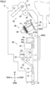
- FIG. 2 is a side view which schematically shows one yarn winding unit 2.
- the right side of the sheet of FIG. 2 will be referred to as the front side in the front-rear direction, and the left side thereof will be referred to as the rear side in the front-rear direction.
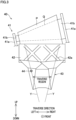
- FIG. 3 is a front view of a later-described winding section 40.
- the yarn winding unit 2 includes a yarn supply section 10, a yarn processing section 20, a yarn storage device 30, and the winding section 40.
- the yarn supply section 10 is able to supply a yarn Y wound onto a yarn supplying bobbin B.
- the yarn processing section 20 is able to perform various processes for the yarn Y supplied from the yarn supply section 10.
- the yarn storage device 30 is able to temporarily store the yarn Y processed by the processing section 20.
- the winding section 40 is able to form a package P by pulling the yarn Y out from the yarn storage device 30 and winding the yarn Y onto a take up tube Q.
- the yarn supply section 10, the yarn processing section 20, the yarn storage device 30, and the winding section 40 are aligned in this order. In this regard, the yarn supply section 10 is the lowest in position while the winding section 40 is the highest in position.
- the yarn supply section 10 includes a yarn unwinding assisting device 11.
- the yarn unwinding assisting device 11 is configured to assist the unwinding of the yarn Y from the yarn supplying bobbin B.
- the yarn unwinding assisting device 11 is configured to restrict, by means of an adjusting cylinder 12, a balloon which is a bulge formed at the time of unwinding of the yarn Y from the yarn supplying bobbin B.
- the adjusting cylinder 12 is configured to move downward as the amount of the yarn Y wound on the yarn supplying bobbin B decreases, so as to keep the size of the bulge to be constant.
- the yarn processing section 20 includes an upper yarn capturing section 21, a yarn joining device 22, a lower yarn capturing section 23, a tensioner 24, and a yarn monitoring device 25.
- the upper yarn capturing section 21, the yarn joining device 22, the lower yarn capturing section 23, the tensioner 24, and the yarn monitoring device 25 are aligned in this order from the upstream side to the downstream side in the yarn running direction.
- the upstream side in the yarn running direction may be simply referred to as the upstream side.
- the downstream side in the yarn running direction may be simply referred to as the downstream side.
- one part of the disconnected yarn Y is provided on the yarn supply section 10 side (the lower side, i.e., the upstream side) and may be referred to as a lower yarn. Furthermore, the other part of the disconnected yarn Y is provided on the winding section 40 side (the upper side, i.e., the downstream side) and may be referred to as an upper yarn.
- the upper yarn capturing section 21 is configured to capture and guide the upper yarn (i.e., a part of the yarn Y provided above the yarn joining device 22 and below the yarn storage device 30 in this case) to the yarn joining device 22.
- the upper yarn capturing section 21 is provided immediately below the yarn joining device 22.
- the upper yarn capturing section 21 is connected to an unillustrated negative pressure source. When the upper yarn is joined with the lower yarn, the upper yarn capturing section 21 sucks, captures, and guides the upper yarn to the yarn joining device 22.
- the yarn joining device 22 is configured to perform yarn joining for the disconnected yarn Y.
- the yarn joining device 22 is able to join the upper yarn (a part of the yarn Y provided on the yarn storage device 30 side) with the lower yarn (a part of the yarn Y provided on the yarn supply section 10 side).
- the yarn joining device 22 is able to join one part of the yarn Y with the other part of the yarn Y.
- the one part of the yarn Y is provided on the yarn supply section 10 side
- the other part of the yarn Y is provided on the yarn storage device 30 side.
- Examples of the case where the yarn Y is disconnected between the yarn supply section 10 and the yarn storage device 30 include (i) a case where the yarn monitoring device 25 detects a yarn defect and cuts the yarn Y, (ii) a case where the yarn Y is broken between the yarn supplying bobbin B and the package P, and (iii) a case where the yarn supplying bobbin B is replaced.
- the yarn joining device 22 is provided behind a yarn path where the yarn Y runs.
- the yarn joining device 22 is configured to join yarn ends of the upper and lower yarns with each other in a case where the yarn ends thereof are guided to the yarn joining device 22 by the upper yarn capturing section 21 and the lower yarn capturing section 23.
- a splicer using fluid such as compressed air, etc. or a mechanical knotter is used as the yarn joining device 22.
- the lower yarn capturing section 23 is configured to capture and guide the lower yarn (i.e., a part of the yarn Y provided below the yarn joining device 22 in this case) to the yarn joining device 22.
- the lower yarn capturing section 23 is a cylindrical member whose leading end portion is provided with an opening.
- the lower yarn capturing section 23 is connected to an unillustrated negative pressure source.
- the lower yarn capturing section 23 is rotatable by a drive section(not illustrated) so that the opening provided at the leading end portion of the lower yarn capturing section 23 is movable between (i) a position (indicated by full lines in FIG. 2 ) provided downstream (above) the adjusting cylinder 12 and (ii) a position (indicated by two-dot chain lines in FIG.
- the leading end portion of the lower yarn capturing section 23 is also provided with a clamp lid closing this opening. As this clamp lid is closed, the sucked yarn is clamped at the same time as suction is stopped.
- the lower yarn capturing section 23 sucks and captures the yarn end of the lower yarn sent from the yarn supplying bobbin B by a later-described assistance blowing sending section 13.
- the leading end portion of the lower yarn capturing section 23 is moved to the downstream side of the yarn joining device 22 while the yarn end of the lower yarn is captured, the lower yarn capturing section 23 guides this yarn end to the yarn joining device 22.
- the assistance blowing sending section 13 is provided immediately below the conveyance tray T supporting the yarn supplying bobbin B.
- the assistance blowing sending section 13 is provided for pulling a yarn end of a yarn Y (the lower yarn) out from a new yarn supplying bobbin B onto which this yarn Y is wound in a case where this yarn supplying bobbin B is supplied to the yarn supply section 10.
- the conveyance tray T and the yarn supplying bobbin B are hollow.
- the assistance blowing sending section 13 is able to eject the compressed air into the internal space of the conveyance tray T and that of yarn supplying bobbin B.
- the ejected compressed air blows off and sends the yarn end of the lower yarn upward (toward the lower yarn capturing section 23 side).
- the yarn end of the lower yarn is captured by the lower yarn capturing section 23.
- the tensioner 24 is able to apply predetermined tension to the running yarn Y.
- the tensioner 24 may be a so-called gate-type device including fixed comb teeth (not illustrated) whose positions are fixed and movable comb teeth (not illustrated) which are movable with respect to the fixed comb teeth.
- the tensioner 24 may be a so-called disc-type device including a disc (not illustrated) applying a resistance force due to friction to the yarn Y.
- the yarn monitoring device 25 is able to detect a defect included in the yarn Y (a yarn defect) and to cut the yarn Y.
- the yarn monitoring device 25 includes a monitoring section 25a and a cutter 25b.
- the monitoring section 25a is able to monitor, e.g., the thickness of the yarn Y by means of a sensor.
- the cutter 25b is able to cut the yarn Y on the yarn path. When the monitoring section 25a detects a yarn defect, the yarn monitoring device 25 immediately cuts the yarn Y by means of the cutter 25b.
- the yarn processing section 20 further includes, e.g., an upper yarn blowing sending section 27 and a yarn guiding member 28.
- the upper yarn blowing sending section 27 is a substantially cylindrical member.
- the upper yarn blowing sending section 27 is provided immediately upstream of the yarn storage device 30.
- the upper yarn blowing sending section 27 is configured to eject the compressed air so as to blow off the yarn end of the upper yarn (a part of the yarn Y provided on the yarn storage device 30 side) toward the upper yarn capturing section 21.
- the yarn guiding member 28 is a pipe-shaped member which extends roughly in the up-down direction and in which the yarn Y passes.
- An inlet section from which the yarn Y enters is formed at an upper end portion of the yarn guiding member 28, and an outlet section from which the yarn Y exits is formed at a lower end portion thereof.
- This inlet section and this outlet section extend at least in the front-rear direction.
- An intermediate part of the yarn guiding member 28 protrudes forward as compared to the inlet section and the outlet section, and extends in the up-down direction.
- the yarn guiding member 28 is provided to bypass the yarn monitoring device 25, the tensioner 24, the yarn joining device 22, etc. Both ends of the yarn guiding member 28 in its longitudinal direction are respectively provided with openings.
- the upper one of these openings opposes an outlet port of the upper yarn blowing sending section 27.
- the lower one of these openings opposes the upper yarn capturing section 21.
- a rear part of the yarn guiding member 28 is provided with a slit (not illustrated) extending over the entire length of the yarn guiding member 28 in its longitudinal direction. After passing through the inside of the yarn guiding member 28 in the longitudinal direction of the yarn guiding member 28, the yarn Y comes out of the yarn guiding member 28 through this slit.
- the upper yarn blowing sending section 27 is configured to capture and blow off the yarn end of the upper yarn to the inside of the yarn guiding member 28. After passing through the yarn guiding member 28 in its longitudinal direction, the yarn Y is sucked and captured by the upper yarn capturing section 21. At this time, the upper yarn which is sucked and captured is pulled rearward so as to come out of the slit of the yarn guiding member 28. Because of this, the upper yarn is guided to the yarn joining device 22.
- the yarn storage device 30 is provided between the yarn processing section 20 and the winding section 40 in the yarn running direction.
- the yarn storage device 30 is configured to pull the yarn Y out from the yarn supply section 10, and able to temporarily store the pulled-out yarn Y.
- the yarn storage device 30 is able to supply the stored yarn Y to the winding section 40 side.
- the yarn storage device 30 makes it possible to suppress the variation of tension of the yarn Y unwound from the yarn supplying bobbin B, from propagating to the winding section 40 side. This suppresses the variation of tension of the yarn Y supplied to the winding section 40. It is therefore possible to form the package P with good quality.
- the yarn Y is temporarily stored by the yarn storage device 30. With this arrangement, while yarn joining is performed, the winding section 40 keeps winding the yarn Y.
- the yarn storage device 30 includes a yarn storage roller 31 and a roller drive motor 32.
- the yarn storage roller 31 is, e.g., a roughly cylindrical member.
- the axial direction, radial direction, and circumferential direction of the yarn storage roller 31 are substantially orthogonal to one another.
- the yarn storage roller 31 includes an outer circumferential surface 31a onto which the yarn Y can be wound.
- the yarn Y is wound onto the outer circumferential surface 31a so as to be temporarily stored.
- the yarn Y wound onto the yarn storage roller 31 is pulled out downward via, e.g., a pull-out guide 35.
- the roller drive motor 32 is able to rotationally drive the yarn storage roller 31.
- the roller drive motor 32 is able to cause the yarn storage roller 31 to rotate in a direction in which the yarn Y is wound onto the yarn storage roller 31 (i.e., rotate normally).
- the roller drive motor 32 is also able to cause the yarn storage roller 31 to rotate in an opposite direction to the direction in which the yarn Y is wound onto the yarn storage roller 31 (i.e., rotate reversely).
- a part of the yarn Y is provided upstream of the yarn storage device 30, and the yarn storage roller 31 is configured to apply tension to this part of the yarn Y by rotating normally while the yarn Y is wound onto the yarn storage roller 31.
- the yarn Y is unwound from the yarn supplying bobbin B and wound onto the outer circumferential surface 31a.
- one side is close to the roller drive motor 32 as compared to the other side and will be referred to as the base end side while the other side will be referred to as the leading end side.
- a tension ring 33 is attached to a leading end portion of the outer circumferential surface 31a of the yarn storage roller 31.
- the tension ring 33 is annularly formed of, e.g., an elastic member (such as rubber).
- the tension ring 33 is attached so as to surround the outer circumferential surface 31a in the circumferential direction of the yarn storage roller 31.
- the tension ring 33 is pressed onto the outer circumferential surface 31a by an elastic force (a biasing force) which is directed inward in the radial direction of the yarn storage roller 31 (hereinafter, this will be simply referred to as the radial direction).
- the yarn Y passes through the inside of the tension ring 33 in the radial direction.
- a friction force between the yarn Y and the tension ring 33 applies a resistance force to the yarn Y pulled out from the yarn storage roller 31. Because of this, the yarn Y is suitably tensioned and reliably unwound from the yarn storage roller 31.
- a groove 31b is formed on the outer circumferential surface 31a of the yarn storage roller 31.
- the groove 31b extends along the axial direction of the yarn storage roller 31 (hereinafter, this will be simply referred to as the axial direction).
- the groove 31b is formed across an attaching position of the tension ring 33 in the axial direction.
- a part of the groove 31b intersects with the tension ring 33, and a biasing member 36 is housed at this part of the groove 31b.
- the biasing member 36 is biased radially outward by an unillustrated spring.
- the biasing member 36 is provided at a position where the biasing member 36 can be pressed radially inward by a later-describe yarn threading nozzle 34. When the biasing member 36 is pressed radially inward, there is a gap between the tension ring 33 and the biasing member 36. This gap allows the yarn Y to go through the inside of the tension ring 33 in the radial direction.
- the yarn storage device 30 further includes a guide mechanism 6.
- the guide mechanism 6 threads this one part of the yarn Y to the yarn storage device 30 and then guides this one part of the yarn Y to the yarn joining device 22.
- this one part of the yarn Y is provided on the package P side or the later-described seed yarn bobbin Bs side.
- the guide mechanism 6 includes the yarn threading nozzle 34, the upper yarn blowing sending section 27 (described above), the yarn guiding member 28 (described above), and the upper yarn capturing section 21 (described above).
- the yarn threading nozzle 34 includes, e.g., a substantially U-shaped groove.
- the yarn threading nozzle 34 is provided in the vicinity of the yarn storage roller 31.
- One end portion of the yarn threading nozzle 34 opposes the leading end portion of the outer circumferential surface 31a of the yarn storage roller 31.
- the yarn threading nozzle 34 is structured so that the compressed air flows from the other end portion to one end portion of the U-shaped groove. This generates an airflow flowing toward the other end portion of the yarn threading nozzle 34 (an end portion of the yarn threading nozzle 34 far from the yarn storage roller 31) so that the yarn Y is sucked by the yarn threading nozzle 34.
- the sucked yarn Y is blown out from one end portion of the yarn threading nozzle 34 (an end portion of the yarn threading nozzle 34 on the yarn storage roller 31 side).
- a linear actuator (not illustrated) including an air cylinder or a motor allows the yarn threading nozzle 34 to move toward or away from the outer circumferential surface 31a of the yarn storage roller 31.
- the yarn Y comes out of a mouth of the U-shaped groove. As a result, the yarn Y comes out of the yarn threading nozzle 34.
- the yarn Y After passing through this gap, the yarn Y is guided by the airflow flowing in the groove 31b from the leading end side (the winding section 40 side) to the base end side (the yarn supply section 10 side) and threaded to the yarn storage roller 31. After being threaded to the yarn storage roller 31 from the leading end side toward the base end side, one yarn end of the yarn Y is sucked by the upper yarn blowing sending section 27, blown toward the yarn guiding member 28, and captured by the upper yarn capturing section 21. As a result, the yarn Y is guided to the yarn joining device 22.
- the winding section 40 includes a cradle 41, a traversing drum 42, and a traverse guide 43.
- the winding section 40 is configured to traverse the yarn Y by means of the traversing drum 42 and the traverse guide 43 while causing the take up tube Q attached to the cradle 41 to rotate by means of the traversing drum 42. This allows the winding section 40 to form the package P by winding the yarn Y onto the take up tube Q.
- the cradle 41 rotatably supports the take up tube Q.
- the cradle 41 is able to cause the outer circumferential surface of the package P to make contact with that of the traversing drum 42.
- the cradle 41 includes a pair of arms 41a and a pair of holders 41b (see FIG. 3 ).
- the pair of the arms 41a are spaced apart from each other in the left-right direction.
- the pair of the arms 41a are swingable about, e.g., the left-right direction which is a swing axis direction.
- the pair of the holders 41b are able to grip both end portions of the take up tube Q in the left-right direction.
- the pair of the holders 41b are respectively provided inside the pair of the arms 41a in the left-right direction, and rotatably attached to the pair of the arms 41a.
- right one of the holders 41b is movable along the rotational axis direction of the take up tube Q.
- the right one of the holders 41b is movable between a grip position where the right holder 41b can grip the take up tube Q and a distanced position where the right holder 41b is spaced apart from the take up tube Q.
- the state of the cradle 41 is switchable between a grip state in which the cradle 41 can grip both ends of the take up tube Q and a detached state in which the grip of the take up tube Q is canceled.
- the traversing drum 42 is configured to cause the package P (or the take up tube Q) to be passively rotated by rotating while being in contact with the outer circumferential surface of the package P (or the take up tube Q).
- the traversing drum 42 is rotationally driven by, e.g., an unillustrated motor.
- the traversing drum 42 is able to rotate so that the yarn Y is wound onto the take up tube Q (i.e., rotate normally).
- the traversing drum 42 is also able to rotate so that the yarn Y is pulled out from the package P (i.e., rotate reversely).
- a traversing groove 42a is formed on the outer circumferential surface of the traversing drum 42.
- the traversing groove 42a makes it possible to traverse the yarn Y in the left-right direction in a predetermined traverse region (see the yarn Y shown in FIG. 3 ).
- the traverse guide 43 is configured to guide the yarn Y traversed by the traversing drum 42 in the left-right direction and to prevent the yarn Y from being lifted forward.
- the traverse guide 43 is provided in front of the traversing drum 42.
- Japanese Laid-Open Patent Publication No. 2018-65659 for example.
- a yarn detection sensor 44 which is able to detect the yarn Y is attached to a left end portion of the traverse guide 43.
- the yarn detection sensor 44 is a reflective optical sensor including, e.g., a light emitting element and a light receiving element. For example, when the yarn Y is detected by the yarn detection sensor 44 at predetermined cycles, it is determined that traversing of the yarn Y is properly performed.
- each yarn winding unit 2 includes the unit controller 2a.
- the unit controller 2a includes, e.g., a CPU, a ROM, a RAM, etc.
- the unit controller 2a is configured to control the operation of each component of the yarn supply section 10, processing section 20, yarn storage device 30, and winding section 40.
- Each unit controller 2a is able to communicate with the machine controller 5.
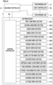
- FIG. 4 is a block diagram of an electric configuration of the automatic winder 1.
- FIG. 5 shows the doffing device 3 viewed from the yarn winding unit 2 side (i.e., the rear side) in the front-rear direction. It should be noted that the left-right direction of FIG. 5 is reverse to that on the sheet of FIG. 5 . The other figures will be described later.
- the doffing device 3 is configured to operate in cooperation with each yarn winding unit 2, and able to perform plural types of processes (predetermined processes) for the yarn winding unit 2.
- the plural types of the predetermined processes include a doffing process, a start process, and a wound yarn breakage dealing process.
- Each of the doffing process, the start process, and the wound yarn breakage dealing process is equivalent to one of one or more types of predetermined processes of the present invention.
- the doffing process is a process of replacing a completed package P with a new empty take up tube Q in one yarn winding unit 2.
- the start process is a process of preparing a new type of a yarn Y to be wound by the winding section 40.
- the start process is also performed in a type change process of changing the type of the yarn Y wound by the winding section 40. That is, the start process may be performed as a part of the type change process.
- the wound yarn breakage dealing process is a process of removing one part of the yarn Y and guiding the other part of the yarn Y to the yarn joining device 22 in a case where wound yarn breakage (this may be referred to as an upper yarn breakage) occurs so that the yarn Y is disconnected between the package P and the yarn storage device 30 in the yarn running direction.
- wound yarn breakage this may be referred to as an upper yarn breakage
- the doffing device 3 includes a doffing section 7 which is able to perform the doffing process, a start processing section 8 which is able to perform the start process, and a wound yarn breakage dealing section 9 which is able to perform the wound yarn breakage dealing process.
- a doffing section 7 which is able to perform the doffing process
- a start processing section 8 which is able to perform the start process
- a wound yarn breakage dealing section 9 which is able to perform the wound yarn breakage dealing process.
- some constituent features are shared between the doffing section 7, the start processing section 8, and the wound yarn breakage dealing section 9.
- the doffing device 3 is structured as described below in order to shorten the time required by the start process.
- the doffing device 3 further includes a housing 50, a multifunction arm 51, a chucker 52, a cradle opener 53, a suction mouth 54, a seed yarn supplier 55, a vertical guide lever 56, a yarn skipping lever 57, and a stored yarn remover 58.
- the doffing section 7 includes the multifunction arm 51, the chucker 52, and the cradle opener 53.
- the cradle opener 53 is equivalent to a switching section of the present invention.
- the start processing section 8 includes the multifunction arm 51, the chucker 52, the cradle opener 53, the seed yarn supplier 55, the vertical guide lever 56, and the yarn skipping lever 57.
- a combination of the vertical guide lever 56 and the yarn skipping lever 57 is equivalent to a first guide section of the present invention.
- the multifunction arm 51 is equivalent to a yarn guide section of the present invention and a second guide section thereof.
- the wound yarn breakage dealing section 9 includes the suction mouth 54, the vertical guide lever 56, the yarn skipping lever 57, and the stored yarn remover 58.
- the housing 50 is, e.g., a box-shaped member which is long in the up-down direction. An opening is provided on a rear surface of the housing 50.
- the multifunction arm 51, the chucker 52, the cradle opener 53, the suction mouth 54, the seed yarn supplier 55, the vertical guide lever 56, the yarn skipping lever 57, and the stored yarn remover 58 are housed in or attached the housing 50.
- FIG. 6(a) shows the multifunction arm 51 viewed from behind.
- FIG. 6(b) shows the multifunction arm 51 viewed from above.
- the multifunction arm 51 is used in the doffing process and the start process.
- the multifunction arm 51 includes, e.g., an arm section 61, a guide section 62, and a clamp cutter section 63.
- the multifunction arm 51 is able to guide and/or to cut and hold the yarn Y in various situations by driving the guide section 62 and the clamp cutter section 63 which are attached to the arm section 61.
- the arm section 61 includes, e.g., a first arm member 64 and a second arm member 65.
- the first arm member 64 extends at least in, e.g., the up-down direction.
- an upper end portion of the first arm member 64 is supported by a right end portion of the housing 50 via a swing shaft 64a extending in the left-right direction.
- the first arm member 64 is swung about the swing shaft 64a by, e.g., a first arm drive section 101 (see FIG. 4 ) including an unillustrated motor.
- the second arm member 65 extends at least in, e.g., the left-right direction.
- a right end portion of the second arm member 65 is attached to the first arm member 64 via a swing shaft 65a extending at least in, e.g., the up-down direction.
- the second arm member 65 is swung about the swing shaft 65a by, e.g., a second arm drive section 102 (see FIG. 4 ) including an unillustrated motor.
- the guide section 62 and the clamp cutter section 63 are attached to a left end portion (leading end portion) of the second arm member 65.
- the guide section 62 is able to guide the yarn Y.
- the guide section 62 includes a base member 66 (see FIG. 6(b) ) and a guide member 67.
- the base member 66 is attached to the second arm member 65 via a swing shaft 66a extending at least in, e.g., the up-down direction.
- the base member 66 is swung about the swing shaft 66a by, e.g., a guide drive section 103 (see FIG. 4 ) including an unillustrated motor.
- the guide member 67 bends the yarn Y to guide the yarn Y along a predetermined yarn path.
- the guide member 67 is fixed to, e.g., a leading end portion of the base member 66. As shown in FIGs.
- the guide member 67 includes, e.g., a first hooking portion 67a and a second hooking portion 67b.
- the first hooking portion 67a is provided below a later-described clamp cutter 69.
- the second hooking portion 67b is provided above the clamp cutter 69.
- the clamp cutter section 63 includes, e.g., a link mechanism 68 and the clamp cutter 69.
- the link mechanism 68 is attached to, e.g., the base member 66.
- the link mechanism 68 is included in, e.g., a swing drive section 104 (see FIG. 4 ) including an unillustrated air cylinder.
- the swing drive section 104 is configured to swing the clamp cutter 69 at least in the front-rear direction.
- the clamp cutter 69 is able to cut and hold the yarn Y.
- the clamp cutter 69 includes an unillustrated cutter configured to cut the yarn Y and an unillustrated clamp configured to hold the yarn Y.
- the link mechanism 68 allows the clamp cutter 69 to swing at least in the front-rear direction.
- the clamp cutter 69 is configured to cut the yarn Y substantially at the same time as to hold a yarn end of the cut yarn Y (specifically, to cut the yarn Y after holding the yarn Y) by means of, e.g., a clamp cutter drive section 105 (see FIG. 4 ) including an unillustrated air cylinder.
- the guide section 62 and the clamp cutter section 63 are movable in a relatively-large area.
- the guide section 62 and the clamp cutter section 63 are movable together by means of the first arm drive section 101 and the second arm drive section 102.
- the guide section 62 and the clamp cutter section 63 are able to move independently from each other by means of the guide drive section 103 and the swing drive section 104.
- the guide member 67 is moved by the guide drive section 103 so as to change the relative position of the yarn path with respect to the clamp cutter 69.
- the yarn Y hooked by the first hooking portion 67a and the second hooking portion 67b is positioned at or moved away from a position where the yarn Y can be cut and held by, e.g., the clamp cutter 69.
- the clamp cutter section 63 is able to be moved close to or spaced apart from the guide member 67 by the swing drive section 104.
- the chucker 52 (see FIG. 5 ) is used in the doffing process and the start process.
- the chucker 52 is provided at, e.g., the center of the housing 50 in the left-right direction.
- the chucker 52 is rotated about, e.g., a shaft 52a extending in the left-right direction by a chucker drive section 106 (see FIG. 4 ) including an unillustrated motor.
- a leading end portion of the chucker 52 is provided with a chucking portion 52b which is able to grip the take up tube Q.
- the chucker 52 takes an empty take up tube Q out from an unillustrated stocker provided at an upper end portion of the automatic winder 1, grips the take up tube Q by means of the chucking portion 52b, and rotates downward.
- the empty take up tube Q is provided between the pair of the arms 41a.
- the cradle opener 53 (see FIG. 5 ) is used in the doffing process and the start process.
- the cradle opener 53 is provided in the vicinity of, e.g., the right end portion of the housing 50.
- the cradle opener 53 is driven by an opener drive section 107 (see FIG. 4 ) including a suitable driving source such as an air cylinder or a motor.
- the cradle opener 53 is configured to perform various operations such as swing and rotation so as to operate an unillustrated cradle lever provided at the cradle 41. For example, as the cradle lever is operated, the right arm 41a and the right holder 41b which are included in the cradle 41 are open or closed. This allows (i) the package P to be detached from the cradle 41 and (ii) the empty take up tube Q to be attached to the cradle 41.
- the suction mouth 54 (see FIG. 5 ) is configured to suck and hold a yarn end of the yarn Y (upper yarn) wound onto the package P in the wound yarn breakage dealing process.
- the suction mouth 54 is provided roughly at the same position as the package P in the up-down direction.
- a rear end of the suction mouth 54 is provided with a suction port 54a extending in the left-right direction.
- the suction mouth 54 is movable between a standby position and a near position which is closer to the yarn winding unit 2 than the standby position is in the front-rear direction.
- the suction mouth 54 is moved between the standby position and the near position by a mouth drive section 108 (see FIG. 4 ).
- the suction mouth 54 is connected to an unillustrated negative pressure source.
- the suction mouth 54 is able to suck and hold the yarn Y by means of negative pressure generated at the suction port 54a by the negative pressure source.
- a mouth cutter 54b which is able to cut the yarn Y is provided in the vicinity of (immediately below), e.g., a right end portion of the suction mouth 54.
- the mouth cutter 54b is driven by, e.g., a mouth cutter drive section 109 (see FIG. 4 ) including an unillustrated air cylinder.
- a leading end of the suction mouth 54 is provided with a contact sensor (not illustrated).
- the detection of the contact sensor allows the mouth drive section 108 to cause and adjust the suction mouth 54 to stop at the near position which is suitable to suck and hold a yarn end of the yarn Y (upper yarn) wound onto the package P.
- a distance sensor configured to detect the distance between two objects in a contactless manner may be provided. This contact sensor may be configured to detect the near position of the suction mouth 54 only at the first time of positional adjustment of the suction mouth 54 so that, thereafter, the near position of the suction mouth 54 is calculated based on the diameter of the package P calculated based on how long the yarn Y is wound onto the package P.
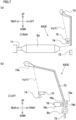
- FIG. 7(a) is an enlarged view of the seed yarn supplier 55 shown in FIG. 5 .
- FIG. 7(b) shows the seed yarn supplier 55 viewed from the left side in the left-right direction.
- the seed yarn supplier 55 is able to supply a new type of a yarn Y (hereinafter, this will be referred to as the seed yarn Ys) in the start process.
- the type of the seed yarn Ys is preferably the same as, e.g., that of the yarn Y wound onto a new yarn supplying bobbin B.
- the seed yarn supplier 55 includes a seed yarn bobbin supporter 71, a seed yarn blowing nozzle 72, a seed yarn guide pipe 73, a seed yarn suction 74, a seed yarn clamp cutter 75, and a stopper section 76 (see FIG. 7(b) ).
- the seed yarn bobbin supporter 71 is provided in the vicinity of, e.g., the right end portion of the housing 50.
- the seed yarn bobbin supporter 71 supports a bobbin onto which the seed yarn Ys is wound (hereinafter, this will be referred to as the seed yarn bobbin Bs) to be, e.g., substantially horizontal.
- the seed yarn bobbin Bs is provided in the housing 50 to extend in the left-right direction.
- the seed yarn blowing nozzle 72 is configured to blow (guide) the seed yarn Ys, e.g., upward.
- the seed yarn blowing nozzle 72 is provided in the vicinity of, e.g., a left end portion of the housing 50.
- the seed yarn blowing nozzle 72 includes, e.g., an ejection port (not illustrated) provided for ejecting the compressed air upward.
- the ejection port opposes an inlet of seed yarn guide pipe 73.
- the seed yarn guide pipe 73 is configured to guide a leading end portion of the seed yarn Ys, which is blown by the seed yarn blowing nozzle 72, toward the seed yarn suction 74.
- the seed yarn guide pipe 73 is a bent pipe-shaped member. Both ends of the seed yarn guide pipe 73 in its longitudinal direction are respectively provided with openings.
- the seed yarn Ys enters the seed yarn guide pipe 73 from one opening (inlet) provided to oppose the ejection port of the seed yarn blowing nozzle 72.
- the seed yarn guide pipe 73 extends roughly upward and rearward as compared to this inlet.
- the seed yarn Ys comes out from the seed yarn guide pipe 73 from the other opening (outlet) oriented, e.g., downward.
- a curved surface 73a (see FIG. 7(b) ) is provided to be curved so that, e.g., the blown seed yarn Ys is guided downward and forward.
- the seed yarn suction 74 is able to suck and capture a yarn end of the seed yarn Ys.
- the seed yarn suction 74 includes, e.g., a suction port which is open on the rear side in the front-rear direction. For example, this suction port is provided below and in front of the outlet of the seed yarn guide pipe 73.
- the suction port is connected to an unillustrated negative pressure source.
- the seed yarn suction 74 is configured to suck and capture (see FIG. 7(a) ) the seed yarn Ys coming out from the outlet of the seed yarn guide pipe 73, by means of negative pressure. After being captured and sucked by the seed yarn suction 74, the seed yarn Ys is cut and held (see FIG. 7(b) ) by, e.g., the seed yarn clamp cutter 75.
- the seed yarn clamp cutter 75 is able to cut and hold the seed yarn Ys.
- the seed yarn clamp cutter 75 is provided on the yarn path to the suction port of the seed yarn suction 74 from the outlet of the seed yarn guide pipe 73.
- the seed yarn clamp cutter 75 includes an unillustrated cutter configured to cut the seed yarn Ys and an unillustrated clamp configured to hold the seed yarn Ys.
- the seed yarn clamp cutter 75 is driven by, e.g., a clamp cutter drive section 110 (see FIG. 4 ) including an unillustrated air cylinder.
- the seed yarn clamp cutter 75 is configured to cut the seed yarn Ys substantially at the same time as to hold a yarn end of the cut seed yarn Ys.
- one yarn end of the cut seed yarn Ys is provided on the seed yarn bobbin Bs side and held by the seed yarn clamp cutter 75 (see FIG. 7(b) ).
- the other yarn end of the cut seed yarn Ys is provided on the side opposite to the seed yarn bobbin Bs side and sucked and removed by the seed yarn suction 74.
- the stopper section 76 (see FIG. 7(b) ) is configured to permit and forbid the seed yarn Ys to be pulled out from the seed yarn bobbin Bs. Assume that, e.g., a part of the seed yarn Ys is provided between the ejection port of the seed yarn blowing nozzle 72 and the inlet of the seed yarn guide pipe 73. In this case, the stopper section 76 is able to grip this part of the seed yarn Ys.
- the stopper section 76 includes, e.g., a fixed member 76a, a movable member 76b, and an air cylinder 76c.
- the fixed member 76a is provided in front of, e.g., the ejection port of the seed yarn blowing nozzle 72 and the inlet of the seed yarn guide pipe 73.
- the movable member 76b opposes the fixed member 76a in the front-rear direction.
- the air cylinder 76c is configured to, e.g., transfer the movable member 76b in the front-rear direction.
- the movable member 76b is movable between a distanced position (indicated by full lines in FIG. 7(b) ) and a sandwiching position (indicated by broken lines in FIG. 7(b) ) by, e.g., a stopper drive section 111 (see FIG.
- the distanced position is a position where the movable member 76b is spaced apart from the fixed member 76a.
- the movable member 76b at the distanced position enables to pull the seed yarn Ys out from the seed yarn bobbin Bs.
- the sandwiching position is a position where the movable member 76b is in contact with the fixed member 76a so as to sandwich the seed yarn Ys with the fixed member 76a. Assume that a part of the seed yarn Ys is provided between the seed yarn bobbin Bs and the stopper section 76.
- the movable member 76b at the sandwiching position prohibits to pull out this part of the seed yarn Ys from the seed yarn bobbin Bs.
- the state of the stopper section 76 is switchable between a permissive state of permitting the seed yarn Ys to be pulled out from the seed yarn bobbin Bs and a prohibitive state of forbidding the seed yarn Ys to be pulled out from the seed yarn bobbin Bs.
- the vertical guide lever 56 is used in the start process and the wound yarn breakage dealing process.
- the vertical guide lever 56 is used mainly for pulling the yarn Y downward.
- the vertical guide lever 56 is configured to exert various functions depending on a situation (as detailed later).
- the vertical guide lever 56 is provided in the vicinity of the suction mouth 54 and the seed yarn supplier 55.
- the vertical guide lever 56 is provided immediately behind, e.g., the housing 50.
- the vertical guide lever 56 is rotatable about a rotational shaft 56a extending at least in the front-rear direction.
- the rotational shaft 56a is provided in the vicinity of the yarn skipping lever 57 in the up-down direction.
- the vertical guide lever 56 is rotated by, e.g., a vertical guide lever drive section 112 (see FIG. 4 ) including an unillustrated motor.
- the vertical guide lever drive section 112 is able to cause the vertical guide lever 56 to rotate clockwise and counterclockwise when viewed behind.
- a leading end portion of the vertical guide lever 56 is provided with a first hooking portion 56b and a second hooking portion 56c.
- the first hooking portion 56b is able to hook the yarn Y.
- the second hooking portion 56c is able to hook the yarn Y.
- the yarn skipping lever 57 is used in the start process and the wound yarn breakage dealing process.
- the yarn skipping lever 57 is swingable about, e.g., a swing shaft 57a extending in the left-right direction. As shown in FIG. 5 , for example, the swing shaft 57a is provided at a lower end portion of the doffing device 3.
- the yarn skipping lever 57 is swung by, e.g., a yarn skipping lever drive section 113 (see FIG. 4 ) including an unillustrated motor.
- a leading end portion of the yarn skipping lever 57 is provided with a yarn picking portion 57b in order to pick up the yarn Y.
- the yarn skipping lever 57 is configured to pick up the yarn Y, which is pulled downward by the vertical guide lever 56, by means of the yarn picking portion 57b and to guide this yarn Y to the other end portion of the yarn threading nozzle 34 of the yarn storage device 30.
- the yarn picking portion 57b is movable between a standby position to pick up the yarn Y and an introduction position provided behind the standby position.
- the introduction position is a position to guide the yarn Y picked up by the yarn picking portion 57b to the other end portion of the yarn threading nozzle 34.
- FIG. 8(a) shows the stored yarn remover 58 viewed in a predetermined direction orthogonal to the up-down direction.
- FIG. 8(b) shows the stored yarn remover 58 viewed at a different angle from FIG. 8 (a).
- FIG. 8 (c) illustrates a later-described hooking section 82 (separation section of the present invention).
- the stored yarn remover 58 is used in the wound yarn breakage dealing process.
- the stored yarn remover 58 is able to remove one part of the yarn Y in a case where the yarn Y is unintentionally disconnected between the yarn storage device 30 and the winding section 40 in the yarn running direction.
- one part of the yarn Y (hereinafter, this will be referred to as the stored yarn) is wound onto the yarn storage device 30.
- the stored yarn remover 58 includes a stored yarn suction 81, the hooking section 82, and a cutting section 83.
- the stored yarn suction 81 is able to suck and capture the stored yarn wound onto the yarn storage roller 31.
- the stored yarn suction 81 is able to suck and remove the cut stored yarn.
- the stored yarn suction 81 includes a suction port 81a (see FIG. 8(b) ) and a cutter 81b.
- the suction port 81a and the cutter 81b are provided at a leading end portion of the stored yarn suction 81.
- the stored yarn suction 81 is connected to an unillustrated negative pressure source via, e.g., a flexible hose 81c which is deformable.
- the stored yarn suction 81 is able to suck the stored yarn by means of negative pressure generated at the suction port 81a by the negative pressure source.
- the cutter 81b is provided in the vicinity of the suction port 81a. The cutter 81b is able to cut the stored yarn which is sucked and captured by the suction port 81a.
- the stored yarn suction 81 is moved freely to some degree in the front-rear, left-right, and up-down directions by, e.g., a stored yarn remover drive section 114 (see FIG. 4 ) and a suction drive section 115 (see FIG. 4 ).
- the stored yarn remover drive section 114 is configured to transfer the stored yarn suction 81, the hooking section 82, and the cutting section 83 together.
- the suction drive section 115 is configured to transfer the stored yarn suction 81 independently from the hooking section 82 and the cutting section 83.
- the hooking section 82 is configured to space a part of the tension ring 33 apart from the outer circumferential surface 31a of the yarn storage roller 31.
- the stored yarn remover drive section 114 (see FIG. 4 ) allows the hooking section 82 to move together as the stored yarn suction 81.
- the hooking section 82 includes, e.g., a rotating plate 82a and a hook 82b.
- the rotating plate 82a is rotatable about, e.g., a rotational shaft 82c which is substantially parallel to a thickness direction of the rotating plate 82a.
- the hook 82b is provided for hooking the tension ring 33.
- the hook 82b is fixed to the rotating plate 82a, and rotatable together as the rotating plate 82a.
- the hooking section 82 is rotatable between a standby position (indicated by full lines in FIG. 8(c) ) and a pulling position (indicated by two-dot chain lines in FIG. 8(c) ).
- the hooking section 82 is rotated by a hooking drive section 116 (see FIG. 4 ) including an unillustrated motor.
- the cutting section 83 (see FIG. 8(a) and FIG. 8(b) ) is able to cut a yarn layer (a later-described yarn layer Yr) including the stored yarn wound onto the outer circumferential surface 31a of the yarn storage roller 31.
- the cutting section 83 is movable together as the stored yarn suction 81 by means of the stored yarn remover drive section 114 (see FIG. 4 ).
- the cutting section 83 includes a main body 83a, fixed blades 83b, movable blades 83c (see FIG. 8(b) ), and a stored yarn sensor 83d (see FIG. 8(a) ; detection section of the present invention).
- the main body 83a supports the fixed blades 83b, movable blades 83c, and the stored yarn sensor 83d.
- the main body 83a can be moved in a direction (hereinafter, this will be simply referred to as the orthogonal direction; see FIG. 18(a) ) which is substantially parallel to the axial direction of the yarn storage roller 31 (see FIG. 2 ) by, e.g., a cutting drive section 117 (see FIG. 4 ) including an unillustrated motor.
- the cutting drive section 117 is preferably able to reciprocate the main body 83a in the radial direction of the yarn storage roller 31 while transferring the main body 83a in the orthogonal direction.
- Such the cutting drive section 117 may be achieved by, e.g., a suitable cam mechanism (not illustrated) using a single driving source (not illustrated). Alternatively, driving sources (not illustrated) may be provided for moving the main body 83a as described above.
- the fixed blades 83b are fixed to, e.g., the main body 83a. Each fixed blade 83b extends in a predetermined extending direction with respect to the main body 83a.
- the fixed blades 83b are aligned in a direction (hereinafter, this will be simply referred to as the arrangement direction; see FIG. 8(b) ) orthogonal to the extending direction.
- the fixed blades 83b can be aligned in the orthogonal direction. In other words, the arrangement direction may be substantially parallel to the orthogonal direction.
- the movable blades 83c are aligned in the arrangement direction in the same manner as the fixed blades 83b. Each movable blade 83c extends in a direction substantially parallel to the extending direction of the fixed blades 83b.
- the movable blades 83c are adjacent to the fixed blades 83b in a direction (the left-right direction on the sheet of FIG. 8(b) ) orthogonal to both the extending direction and the arrangement direction.
- the movable blades 83c can be provided to be adjacent to the fixed blades 83b in the circumferential direction of the yarn storage roller 31.
- the movable blades 83c can be reciprocated in the orthogonal direction by, e.g., the cutting drive section 117.
- the stored yarn sandwiched between the fixed blades 83b and the movable blades 83c is efficiently cut under the same principle as a pair of hair clippers provided for cutting hair.
- the fixed blades 83b and the movable blades 83c are able to at least partially enter the inside of the groove 31b of the yarn storage roller 31 in the radial direction of the yarn storage roller 31 (see FIG. 2 ) .
- the stored yarn sensor 83d is able to detect a yarn layer.
- the stored yarn sensor 83d is, e.g., a known reflective optical sensor.
- the stored yarn sensor 83d may be fixed to, e.g., the main body 83a.
- the doffing device 3 includes the doffing controller 3a (a controller of the present invention).
- the doffing controller 3a includes, e.g., a CPU, a ROM, and a RAM.
- the doffing controller 3a is able to communicate with the machine controller 5.
- the doffing controller 3a is configured to control the sections of the doffing device 3 based on instructions from the machine controller 5.
- the yarn winding unit 2 is configured to operate in cooperation with the doffing device 3 so that the doffing process, the start process, and the wound yarn breakage dealing process are automatically performed without human intervention. The following will describe each of these processes.
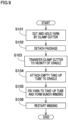
- FIG. 9 is a flowchart of steps of the doffing process.
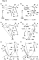
- FIG. 10(a) to FIG. 10 (c) is a side view of the multifunction arm 51 and its surroundings, and schematically illustrates the operation of the multifunction arm 51.
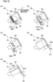
- FIG. 11(a) to FIG. 11(c) is a front view of the cradle 41 and its surroundings, and schematically illustrates the operation of fixing the yarn Y to the take up tube Q.
- the unit controller 2a of this yarn winding unit 2 determines that the formation of the package P is completed. At this time, the unit controller 2a stops the rotation of the traversing drum 42 and that of the yarn storage roller 31. To be more specific, the unit controller 2a decelerates the traversing drum 42 while determining whether the yarn detection sensor 44 detects the yarn Y. For example, as the yarn Y reaches a right end of the traverse region (see FIG. 3 ), the unit controller 2a stops the rotation of the traversing drum 42. This also stops the rotation of the package P. At this time, the yarn Y is still connected between the package P and the yarn storage device 30.
- the unit controller 2a When the formation of the package P is completed, the unit controller 2a outputs a signal to request the doffing process.
- the machine controller 5 transmits this signal to the doffing controller 3a.
- the unit controller 2a is configured to cooperate with the doffing controller 3a via, e.g., the machine controller 5.
- the doffing controller 3a transfers the doffing device 3 to a position in front of the above-described yarn winding unit 2 and starts the doffing process described below.
- the doffing controller 3a suitably controls, e.g., the first arm drive section 101 and the second arm drive section 102 (see FIG. 4 ) to transfer the multifunction arm 51 from a predetermined standby position.
- the doffing controller 3a transfers the guide member 67 and the clamp cutter 69 (see FIG. 10(a) ) to a cutting holding position to cut and hold the yarn Y.
- the cutting holding position is provided in the vicinity of a right end portion of the traverse guide 43 in the left-right direction and immediately above the traverse guide 43.
- the doffing controller 3a controls the clamp cutter drive section 105 (see FIG. 4 ) to cause the clamp cutter 69 to cut and hold the yarn Y (step S101; see FIG. 10 (b) ).
- One part of the yarn Y (lower yarn) is then provided on the yarn storage device 30 side and held by the clamp cutter 69.
- the unit controller 2a causes the traversing drum 42 to rotate normally so that the other part of the yarn Y is wound onto the package P.
- the other part of the yarn Y (upper yarn) is provided on the winding section 40 side.
- the doffing controller 3a causes the doffing device 3 to perform the operation of detaching the package P from the cradle 41 (step S102).
- the doffing controller 3a controls the opener drive section 107 (see FIG. 4 ) to cause the cradle opener 53 to operate the cradle lever of the cradle 41. This causes the pair of the arms 41a to be open in the left-right direction (be in the above-described detached state) and, for example, to swing upward and rearward (swing away from the doffing device 3 in the front-rear direction).
- the package P is then released from the pair of the holders 41b and detached from the cradle 41 by, e.g., its own weight. After that, the package P having been detached from the cradle 41 is discharged to an unillustrated discharge port.
- the pair of the arms 41a are moved downward and forward (moved to a position immediately above the traversing drum 42) while being in the detached state.
- the doffing controller 3a performs yarn threading for a new take up tube Q (i.e., a take up tube Q to be newly held by the cradle 41).
- the doffing controller 3a transfers the clamp cutter 69 to the vicinity of the cradle 41 (step S103).
- the doffing controller 3a controls the swing drive section 104 to swing the clamp cutter 69 upward and rearward with respect to the guide member 67 (see FIG. 10(c) ).
- the clamp cutter 69 guides the yarn Y to a gap position (see FIG. 11(a) ) where a gap is formed between the new take up tube Q and the cradle 41. That is, the yarn Y extending between the guide member 67 and the clamp cutter 69 is provided at a position where the yarn Y can be sandwiched between the take up tube Q and the right holder 41b.
- the multifunction arm 51 is able to guide a part of the yarn Y to the winding section 40 in a case where yarn threading is performed for a new take up tube Q to be held by the cradle 41. This part of the yarn is provided on the yarn supply section 10 side in the yarn running direction.
- the doffing controller 3a controls the chucker drive section 106 to drive the chucker 52.
- the chucker 52 takes an empty take up tube Q out from an unillustrated stocker by means of the chucking portion 52b, and attaches this take up tube Q to the cradle 41 (step S104) .
- the doffing controller 3a causes that the yarn Y held by the clamp cutter 69 is fixed to the take up tube Q and that then a bunch winding is formed (step S105).
- the bunch winding is a yarn layer which is formed on the take up tube Q and which is out of the traverse region.
- the bunch winding is used for continuously unwinding the yarn Y from plural packages P in a later step.
- the following will describe specific steps of the step S105.
- the doffing controller 3a causes the cradle opener 53 to operate the cradle lever again so that the state of the cradle 41 is switched to the grip state from the detached state. Because of this, the right arm 41a and the right holder 41b are moved leftward (see FIG. 11(b) ).
- the yarn Y is sandwiched by the take up tube Q and the holders 41b and fixed to the take up tube Q.
- the doffing controller 3a causes that the take up tube Q is released from the chucker 52.
- the doffing controller 3a also causes that the yarn Y is released from the clamp cutter 69.
- the doffing controller 3a suitably controls the first arm drive section 101, the second arm drive section 102, and the guide drive section 103 (see FIG. 4 ) to transfer the guide member 67 slightly leftward.
- bunch winding A (see FIG. 11(c) ) is formed.
- the yarn threading is performed by such steps S103 to S105.
- the doffing controller 3a transfers the multifunction arm 51 back to the standby position, and the unit controller 2a causes the traversing drum 42 and the yarn storage roller 31 to rotate normally. This restarts the winding of the yarn Y (step S106).
- FIG. 12 is a flowchart of steps of the start process.
- FIG. 13 is a flowchart of steps of the lower yarn pull-out process (described later) which is a step included in the start process.
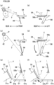
- FIG. 14(a) to FIG. 15(f) schematically illustrates the operation of the start processing section 8.
- FIG. 14(a), FIG. 14(c), FIG. 14(e), FIG. 14(f) , FIG. 15(a), FIG. 15(c), and FIG. 15(e) shows the seed yarn supplier 55 and/or its surroundings viewed from left to right.
- FIG. 15(d) shows the seed yarn supplier 55 and/or its surroundings viewed from behind.
- a direction of rotation of the vertical guide lever 56 (a clockwise or counterclockwise direction) is a direction of the rotation of the vertical guide lever 56 viewed from behind.
- the package P has been detached from the cradle 41.
- the package P may not be detached from the cradle 41 in the initial state, but may be detached from the cradle 41 immediately before later-described yarn threading to the take up tube Q.
- the seed yarn supplier 55 the seed yarn Ys pulled out from the seed yarn bobbin Bs has been guided to the seed yarn clamp cutter 75 through the seed yarn guide pipe 73 and held by the seed yarn clamp cutter 75 (see FIG. 7(b) ).
- the vertical guide lever 56 extends at least upward.
- a new type of the yarn Y (lower yarn) supplied from the yarn supplying bobbin B may be captured by the lower yarn capturing unit 23 in advance.
- the lower yarn may be captured by the lower yarn capturing unit 23 in parallel to the start process.
- the state of the stopper section 76 is the permissive state. In this state, as the seed yarn Ys is pulled, the seed yarn Ys is further pulled out from the seed yarn bobbin Bs.
- the doffing controller 3a pulls out the seed yarn Ys by means of the multifunction arm 51 (step S201 shown in FIG. 12 ).
- the doffing controller 3a suitably controls the first arm drive section 101, the second arm drive section 102, and the guide drive section 103 (see FIG. 4 ) to hook the seed yarn Ys by means of the guide member 67 and to pull this seed yarn Ys out rearward (see FIG. 14(a) and FIG. 14(b) ). Because of this, a yarn path of the seed yarn Ys between the guide member 67 and the seed yarn clamp cutter 75 intersects with a movement track of the first hooking portion 56b of the vertical guide lever 56.
- the doffing controller 3a transfers the seed yarn Ys downward by means of the vertical guide lever 56 (step S202).
- the doffing controller 3a controls the vertical guide lever drive section 112 (see FIG. 4 ) to cause the vertical guide lever 56 to make approximately a half turn counterclockwise (see FIG. 14(c) and FIG. 14(d) ). Because of this, the seed yarn Ys is pulled downward. While being pulled downward by the vertical guide lever 56, the seed yarn Ys is picked up by, e.g., the yarn picking portion 57b (indicated by two-dot chain lines in FIG. 14(e) ) at the standby position.
- the doffing controller 3a transfers the seed yarn Ys to the vicinity of the yarn threading nozzle 34 by means of the yarn skipping lever 57 (step S203) .
- the doffing controller 3a controls the yarn skipping lever drive section 113 (see FIG. 4 ) to transfer the yarn picking portion 57b from the standby position (indicated by two-dot chain lines in FIG. 14(e) ) to the introduction position (indicated by full lines in FIG. 14(e) ). Because of this, the seed yarn Ys is guided to the vicinity of the other end portion of the yarn threading nozzle 34. That is, in the start process, the seed yarn Ys is guided to the guide mechanism 6 by the vertical guide lever 56 and the yarn skipping lever 57 (a first guide process of the present invention).
- the doffing controller 3a controls the clamp cutter drive section 110 (see FIG. 4 ) to release the seed yarn Ys from the seed yarn clamp cutter 75 (step S204; see FIG. 14(f) ).
- the released seed yarn Ys then passes through the guide mechanism 6 including the yarn threading nozzle 34, is captured by the upper yarn capturing section 21, guided by the yarn joining device 22, and set to be a yarn joining preparation state (step S205).
- the principle by which the seed yarn Ys is guided to the yarn joining device 22 by the guiding mechanism 6 is the same as the principle by which the yarn Y is guided to the yarn joining device 22 by the guiding mechanism 6 (described above).
- the doffing device 3 is able to guide the seed yarn Ys to the yarn joining device 22 in the start process. If the yarn joining is performed in this state, a joint between the seed yarn Ys and the lower yarn (hereinafter, this will be simply referred to as the joint) is provided in the vicinity of the yarn joining device 22.
- the doffing controller 3a controls the stopper drive section 111 to set the stopper section 76 (see FIG. 7(b) ) in the prohibitive state. Because of this, the seed yarn Ys is forbidden to be pulled out from the seed yarn bobbin Bs (step S206; a prohibitive process of the present invention). In this state, the doffing controller 3a performs the lower yarn pull-out process (step S207). To put it simply, the lower yarn pull-out process is performed for pulling the joint downstream and removing the seed yarn Ys joined with the lower yarn.
- the doffing controller 3a transfers the vertical guide lever 56 to a preparation position (step S301 shown in FIG. 13 ).
- the doffing controller 3a controls the vertical guide lever drive section 112 (see FIG. 4 ) to cause the vertical guide lever 56 to, e.g., make approximately a half turn clockwise (see FIG. 15 (a) and FIG. 15(b) ). Because of this, the vertical guide lever 56 is provided at a position to extend upward (preparation position) .
- the step S301 is performed, the yarn path of the seed yarn Ys is far from the movement track of the vertical guide lever 56 (see FIG. 15(a) ). Because of this, the vertical guide lever 56 does not interfere with the seed yarn Ys.
- the doffing controller 3a performs the step S301 after the step S206.
- a timing to perform the step S301 is not limited to this.
- the step S301 may be performed after the above-described step S204 and before the step S206.
- the vertical guide lever 56 may rotate counterclockwise.
- the doffing controller 3a then transfers the guide member 67 of the multifunction arm 51 to a predetermined pull-out possible position (step S302).
- the doffing controller 3a suitably controls the first arm drive section 101, the second arm drive section 102, and the guide drive section 103 (see FIG. 4 ) to transfer the guide member 67 so that the yarn path of the seed yarn Ys intersects with the movement track of the second hooking portion 56c of the vertical guide lever 56 (see FIG. 15(c) and FIG. 15(d) ).
- the unit controller 2a controls the yarn joining device 22 to join the seed yarn Ys with the lower yarn (step S303) .
- the yarn Y supplied from the yarn supply section 10 is joined with the seed yarn Ys, and the length of the yarn path between the yarn joining device 22 and the stopper section 76 is a predetermined first length.
- the doffing controller 3a causes the vertical guide lever 56 to rotate so that the lower yarn is pulled out (step S304).
- the doffing controller 3a controls the vertical guide lever drive section 112 (see FIG. 4 ) to cause the vertical guide lever 56 to make approximately a half turn clockwise (see FIG. 15(e) and FIG. 15(f) ). Because of this, the yarn Y is hooked and pulled out by the second yarn hooking portion 56c.
- the stopper section 76 forbids the seed yarn Ys to be pulled out from the seed yarn bobbin Bs. Meanwhile, it is not forbidden to pull the yarn Y (lower yarn) out from the yarn supplying bobbin B.
- the lower yarn is pulled out upward (indicated by an upward arrow in FIG. 15(e) and FIG. 15(f) ).
- the lower yarn is pulled out by changing the length of the yarn path between the yarn joining device 22 and the stopper section 76 to be a second length which is larger than the first length.
- the length of this yarn path is changed from the first length to the second length by the vertical guide lever 56 (a yarn path change process of the present invention) in a state in which the yarn Y supplied from the yarn supply section 10 is joined with the seed yarn Ys.
- the vertical guide lever 56 is equivalent to a yarn path change section of the present invention.
- the doffing controller 3a determines whether to further pull out the lower yarn (step S305). Whether to further pull out the lower yarn is determined based on, e.g., whether the seed yarn Ys which has been subjected to the step S303 once or plural times so as to be joined with the lower yarn is reliably prevented from being wound onto the new take up tube Q. To be more specific, whether to further pull out the lower yarn may be determined based on whether the yarn path change process has been performed predetermined times.
- the doffing controller 3a determines to further pull out the lower yarn (Yes in S305) .
- the doffing controller 3a causes the vertical guide lever 56 to slightly rotate counterclockwise so that the seed yarn Ys is loosened (step S306).
- the doffing controller 3a preferably causes the vertical guide lever 56 to rotate so that the second hooking portion 56c is provided in the vicinity of the seed yarn suction 74.
- the loosened seed yarn Ys is then sucked by the seed yarn suction 74 as the doffing controller 3a drives the seed yarn suction 74 (step S307).
- the seed yarn suction 74 is used not only for preparing the seed yarn Ys in the seed yarn supplier 55, but also for removing an unnecessary part of the seed yarn Ys in the lower yarn pull-out process.
- a suction force of the seed yarn suction 74 causes the yarn Y to be tensioned again.
- the vertical guide lever 56 is caused to rotate in a state in which the seed yarn clamp cutter 75 is closed.
- the doffing controller 3a performs the determination of the step S305 again.
- the joint can be sucked by, e.g., the seed yarn suction 74 by pulling out the lower yarn the required number of times. That is, a part of the seed yarn Ys is completely removed. This part thereof is joined with the lower yarn.
- the doffing controller 3a finishes the pull-out of the lower yarn (NO in S305). This makes it possible to proceed to a step next to the lower yarn pull-out process.
- the doffing controller 3a performs yarn threading to the new take up tube Q (step S208 shown in FIG. 12 ). More specifically, to begin with, the doffing controller 3a causes the clamp cutter 69 to cut and hold the yarn Y. Because of this, the clamp cutter 69 cuts an intermediate part of the yarn Y and holds one part of the cut yarn Y. This one part thereof is provided on the yarn joining device 22 side. This one part of the yarn Y includes only the yarn Y supplied from the yarn supplying bobbin B. The other part of the cut yarn Y is provided on the seed yarn bobbin Bs side, and sucked and removed by the seed yarn suction 74.
- the doffing controller 3a performs the same steps as the above-described steps S103 to S106 (see FIG. 9 ).
- the multifunction arm 51 guides the one part of the yarn Y provided on the yarn joining device 22 side to the cradle 41 (a second guide process of the present invention) and performs the yarn threading to the take up tube Q.
- the multifunction arm 51 holds and guides the one part of the yarn Y to the cradle 41 after the yarn path change process.
- the one part of the yarn Y is provided on the yarn joining device 22 side to the cradle 41. As such, the start process is completed.
- the wound yarn breakage dealing process is disconnection of the yarn Y between the yarn storage device 30 and the package P in the yarn running direction, due to any trouble.
- the wound yarn breakage dealing process is roughly divided into two processes (the stored yarn removal process and the upper yarn guide process).
- the stored yarn removal process is a process of removing the yarn Y (stored yarn) stored in the yarn storage device 30.
- the upper yarn guide process is a process of pulling the yarn Y (upper yarn) out from the package P and guiding this yarn Y to the yarn joining device 22.
- the wound yarn breakage dealing process is a process of removing one part of the yarn Y, pulling out the other part of the yarn Y, and guiding the other part of the yarn Y to the yarn joining device 22 via the yarn storage device 30.
- the one part of the yarn Y is stored in the yarn storage device 30, and the other part of the yarn Y is wound onto the package P.
- the wound yarn breakage dealing process for example, the stored yarn removal process is performed first, and the upper yarn guide process is performed next.
- FIG. 16 is a flowchart of steps of the stored yarn removal process.
- FIG. 17(a) to FIG. 18(e) schematically illustrates the operation of the stored yarn remover 58.
- FIG. 18(e) shows the yarn storage roller 31 and its surroundings viewed from left to right.
- FIG. 19 is a flowchart of steps of the upper yarn guide process.
- FIG. 20(a) to FIG. 20(f) schematically illustrates the upper yarn guide process.
- FIG. 20(a), FIG. 20(c), FIG. 20(e), and FIG. 20(f) shows the yarn Y (upper yarn) pulled out from the package P and its surroundings viewed from left to right.
- FIG. 20(b) and FIG. 20(d) shows the upper yarn and its surroundings viewed from behind.
- the stored yarn removal process In an initial state, the yarn Y has been disconnected between the yarn storage device 30 and the package P in the yarn running direction. The yarn storage device 30 and the winding section 40 have been stopped. When the wound yarn breakage occurs, a downstream end portion of the yarn Y (hereinafter, this will be referred to as the stored yarn) stored in the yarn storage device 30 may be loosened. It is very difficult to join a yarn end of the loosened stored yarn again with a yarn end of the yarn Y provided on the package P side. If this yarn joining is successfully performed, the loosened yarn Y may be entangled in, e.g., the yarn storage device 30 so that the yarn winding unit 2 does not properly operate. The stored yarn removal process is therefore necessary in a case where the wound yarn breakage occurs. In the doffing process, because the multifunction arm 51 operates so that the yarn Y stored in the yarn storage device 30 is not loosened, the stored yarn removal process is unnecessary.
- the doffing controller 3a controls the stored yarn remover drive section 114 (see FIG. 4 ) to cause the entire stored yarn remover 58 to approach the yarn storage roller 31 (step S401 shown in FIG. 16 ). To be more specific, the doffing controller 3a transfer the stored yarn suction 81 to, e.g., the vicinity of the tension ring 33 (see FIG. 17(a) ).
- the doffing controller 3a causes the stored yarn suction 81 to suck the stored yarn.
- the unit controller 2a causes the yarn storage roller 31 to rotate reversely (step S402; see FIG. 17(b) ).
- a part of the stored yarn is loosened in the vicinity of the tension ring 33 and sucked by the stored yarn suction 81. This part thereof is close to the yarn end thereof.
- the loosened yarn Y is wound onto the yarn storage roller 31 again while being tensioned to some degree (see FIG. 17(b) ).
- the yarn end of the stored yarn is separated from the stored yarn suction 81 (see FIG. 17(c) ).
- the stored yarn is wound onto the yarn storage roller 31 roughly in the same state as before the wound yarn breakage.
- the groove 31b is provided at, e.g., the lower end portion of the yarn storage roller 31 and prepared for the next operation of the stored yarn remover 58.
- the doffing controller 3a causes the hooking section 82 to pull the tension ring 33 (step S403; see FIG. 17(d) ).
- the doffing controller 3a causes the rotating plate 82a and the hook 82b to rotate, e.g., substantially 90 degrees by means of the hooking drive section 116 so that the hooking section 82 moves from the standby position to the pulling position.
- the hook 82b temporarily enters, e.g., the groove 31b so as to smoothly enter the inside of the tension ring 33 in the radial direction thereof.
- the tension ring 33 is hooked by the hook 82b, and a part of the tension ring 33 is pulled radially outward of the yarn storage roller 31.
- the tension ring 33 is partially lifted up from the outer circumferential surface 31a of the yarn storage roller 31. This causes a part of the tension ring 33 in the circumferential direction of the yarn storage roller 31 to have no force of pressing the stored yarn onto the outer circumferential surface 31a. In this state, as the yarn storage roller 31 rotates normally as described later, the stored yarn smoothly follows the stored yarn suction 81.
- the doffing controller 3a causes the stored yarn suction 81 to suck and capture the yarn end of the stored yarn.
- the unit controller 2a causes the yarn storage roller 31 to rotate normally (step S404; see FIG. 17(e) ). Because of this, a part of the stored yarn is sucked by the stored yarn suction 81. This part thereof is loosened on the downstream side of the tension ring 33 in the yarn running direction.
- the doffing controller 3a causes the cutter 81b to cut the yarn Y in the vicinity of the tension ring 33 (step S405; see FIG. 17(f) ). Because of this, a part of the stored yarn is mostly sucked and removed. This part thereof is provided downstream of the tension ring 33.
- the doffing controller 3a transfers the stored yarn suction 81 and the cutting section 83 so that the cutting section 83 cuts layers of stored yarn (yarn layers Yr; see FIG. 18(a) , etc.; step S406).
- the doffing controller 3a controls the cutting drive section 117 to drive the cutting section 83 (see FIG. 18(a) to FIG. 18(c) ).
- the cutting section 83 While moving toward the base end side in the axial direction of the yarn storage roller 31, the cutting section 83 repeatedly reciprocates in the radial direction of the yarn storage roller 31 (i.e., partially enters and exits the groove 31b).
- the movable blades 83c also reciprocate in the orthogonal direction (see FIG. 18(a) ) with respect to the fixed blades 83b. Because of such operation of the cutting section 83, all stored yarn layers Yr are cut in the axial direction (orthogonal direction) of the yarn storage roller 31. The cut yarn layers Yr are sucked and removed by the stored yarn suction 81.
- the doffing controller 3a preferably uses, e.g., a detection result of the stored yarn sensor 83d and drives the stored yarn suction 81 and the cutting section 83 in the orthogonal direction and only in a region where the yarn layers Yr are detected. After that, the doffing controller 3a transfers the stored yarn suction 81 and the cutting section 83 back to the leading end side in the axial direction of the yarn storage roller 31 (see FIG. 18(d) ).
- the doffing controller 3a suitably controls the hooking section 82 to further pull the tension ring 33 radially outward of the yarn storage roller 31 (step S407).
- the doffing controller 3a transfers the stored yarn suction 81 to the vicinity of the tension ring 33 again (see FIG. 18(d) ).
- the unit controller 2a causes the yarn storage roller 31 to rotate normally or reversely (see FIG. 18(e) ). Because of this, yarn waste is sucked and removed even in a case where the yarn waste slightly remains in the vicinity of the tension ring 33 (step S408). As such, the stored yarn removal process is completed.
- the doffing controller 3a controls, e.g., the mouth drive section 108 to transfer the suction mouth 54 to the near position (step S501 in FIG. 19 ; indicated by two-dot chain lines in FIG. 20(a) ).
- the doffing controller 3a then causes (i) the traversing drum 42 to rotate reversely and (ii) the suction mouth 54 to suck and pull out the upper yarn (step S502).
- the doffing controller 3a transfers the suction mouth 54 to the standby position (step S503; indicated by full lines in FIG. 20(a) ; see FIG. 20(b) ). Because of this, the yarn path of the upper yarn between the package P and the suction mouth 54 intersects with the movement track of the first hooking portion 56b of the vertical guide lever 56.
- the doffing controller 3a causes the vertical guide lever 56 to rotate, e.g., counterclockwise so that the upper yarn is hooked by the first hooking portion 56b and moves downward (step S504; see FIGs. 20(c) and 20(d) ). Because of this, the upper yarn is further pulled out downward from the package P. While being pulled by the vertical guide lever 56, the upper yarn is guided to a position where the upper yarn can be cut by the mouth cutter 54b (see FIG. 20(d) ). Furthermore, for example, while being pulled downward by the vertical guide lever 56, the upper yarn is picked up by the yarn picking portion 57b at the standby position (indicated by two-dot chain lines in FIG. 20(e) ).
- the doffing controller 3a transfers the upper yarn to the vicinity of the yarn threading nozzle 34 by means of the yarn skipping lever 57 (step S505; indicated by full lines in FIG. 20(e) ). Because of this, the upper yarn is guided to the vicinity of the other end portion of the yarn threading nozzle 34. Subsequently, the doffing controller 3a controls the mouth cutter drive section 109 (see FIG. 4 ) to cause the mouth cutter 54b to cut the upper yarn (step S506). Because of this, the upper yarn is guided to the yarn joining device 22 via the guide mechanism 6 (see FIG. 20(f) ).
- the principle by which the upper yarn is guided to the yarn joining device 22 by the guiding mechanism 6 is the same as the principle by which the yarn Y is guided to the yarn joining device 22 by the guiding mechanism 6 (described above).
- the unit controller 2a controls the yarn joining device 22 to join the upper yarn with the lower yarn (step S507). Furthermore, the unit controller 2a causes the traversing drum 42 and the yarn storage roller 31 to rotate normally. This restarts the winding of the yarn Y (step S508). As such, the upper yarn guide process and the wound yarn breakage dealing process are completed.
- the seed yarn Ys is directly guided to the yarn joining device 22 in the start process.
- the time required by the start process is shortened as compared to a case where the formation of a starter package is necessary.
- the doffing device 3 makes it possible to perform the start process and the wound yarn breakage dealing process as plural types of the predetermined processes. It is therefore possible to deal with various situations in the yarn winding unit 2 including the yarn storage device 30 and to further facilitate the automation of the automatic winder 1.
- the wound yarn breakage dealing section 9 is able to cut and remove each yarn layer Yr in the orthogonal direction. By cutting the yarn layer Yr, the yarn Y remaining on the yarn storage roller 31 is easily removed.
- the groove 31b is formed on the outer circumferential surface 31a of the yarn storage roller 31.
- a part of the yarn layer Yr is provided at the same position as the groove 31b in the circumferential direction of the yarn storage roller 31.
- the cutting section 83 is able to at least partially enter the inside of the groove 31b. This allows the cutting section 83 to reliably and easily cut this part of the yarn layer Yr. This also allows the cutting section 83 to avoid making contact with the outer circumferential surface 31a of the yarn storage roller 31, and thus the damage to the outer circumferential surface 31a is reliably prevented.
- the cutting section 83 includes the fixed blades 83b and the movable blades 83c. With this arrangement, the yarn layer Yr is reliably and easily cut under the same principle as a pair of hair clippers provided for cutting hair.
- the doffing controller 3a is configured to use a detection result of the stored yarn sensor 83d and to drive the stored yarn remover 58 only in a region where the yarn layer Yr is detected. With this arrangement, the yarn layer Yr is cut in the minimum region. Therefore, the time required by cutting of the yarn layer Yr is shortened as compared to a case where the yarn layer Yr is cut across the entire region where the yarn layer Yr may be formed in the orthogonal direction.
- the stored yarn remover 58 of the wound yarn breakage dealing section 9 includes the hooking section 82 configured to space at least a part of the tension ring 33 apart from the outer circumferential surface 31a. With this arrangement, the yarn Y gripped between the tension ring 33 and the outer circumferential surface 31a is easily removed. This also allows the stored yarn remover 58 to avoid unintentionally making contact with the tension ring 33 in a case where the stored yarn wound onto the yarn storage roller 31 is cut and removed. It is therefore possible to prevent the stored yarn remover 58 from causing the damage to the tension ring 33.
- the yarn winding unit 2 includes the guide mechanism 6.
- the doffing device 3 includes the vertical guide lever 56, the yarn skipping lever 57, and the multifunction arm 51.
- the seed yarn Ys is directly guided to the yarn joining device 22 by the vertical guide lever 56, the yarn skipping lever 57, and the guide mechanism 6.
- the yarn Y is then guided to the vicinity of the take up tube Q by the multifunction arm 51.
- the doffing controller 3a is configured to perform the first guide process, the prohibitive process, the yarn path change process, and the second guide process. With this arrangement, the start process is automatically performed.
- the multifunction arm 51 guides the yarn Y to the gap position where the gap is formed between the new take up tube Q and the cradle 41. Furthermore, after the new take up tube Q is attached to the cradle 41, the cradle 41 is transferred back to the grip state from the detached state. As a result, before the new take up tube Q is attached to the cradle 41, the yarn Y is guided to the gap position through a large space. It is therefore possible to improve the success rate of the yarn threading.
- the doffing device 3 is configured to perform the doffing process as one type of a predetermined process. This further facilitates the automation of the automatic winder 1. Because the doffing device 3 is able to perform various processes, the automatic winder 1 includes a smaller number of apparatuses as compared to a case where an apparatus is independently provided from the doffing device 3 in order to perform a predetermined process.
- An object of the present invention is to shorten the time required by a start process of starting the winding of a new type of a yarn.
- An automatic winder 1 includes a yarn winding unit 2 and a doffing device 3.
- the yarn winding unit 2 includes a yarn storage device 30 and a yarn joining device 22.
- the yarn storage device 30 is provided between a yarn supply section 10 and a yarn winding section 40 in a yarn running direction, and configured to temporarily store a yarn Y.
- the yarn joining device 22 is provided between the yarn supply section 10 and the yarn storage device 30 in the yarn running direction.
- a doffing device 3 includes a seed yarn supplier 55 which is able to supply a seed yarn Ys from a seed yarn bobbin Bs in the start process.
- the seed yarn supplier 55 is able to guide the seed yarn Ys from the seed yarn bobbin Bs to the yarn joining device 22 via the yarn storage device 30.
Landscapes
- Engineering & Computer Science (AREA)
- Textile Engineering (AREA)
- Quality & Reliability (AREA)
- Replacing, Conveying, And Pick-Finding For Filamentary Materials (AREA)
Abstract
Description
- The present invention relates to a yarn winder.
- Patent Literature 1 (
Japanese Laid-Open Patent Publication No. 2018-65659 - There have recently been demands for further improvement in production efficiency of the yarn winder. When the starter package is formed as described above, the start process of starting the winding of a new type of a yarn takes time.
- An object of the present invention is to shorten the time required by a start process of starting the winding of a new type of a yarn.
- According to a first aspect of the invention, a yarn winder comprises: a yarn winding unit including a winding section configured to form a package by winding a yarn pulled out from a yarn supply section onto a take up tube; and a service unit which is able to perform one or more types of predetermined processes for the yarn winding unit. The yarn winding unit further includes: a yarn storage device which is provided between the yarn supply section and the winding section in a yarn running direction and which is configured to temporarily store the yarn, the yarn running in the yarn running direction; and a yarn joining device which is provided between the yarn supply section and the yarn storage device in the yarn running direction and which is configured to join one part of the yarn provided on the yarn supply section side with the other part of the yarn provided on the yarn storage device side. In this regard, the one or more types of the predetermined processes include a start process of causing the winding section to start winding of the yarn, the service unit includes a seed yarn supplier which is able to supply a seed yarn from a seed yarn bobbin in the start process, the seed yarn is to be joined with the yarn pulled out from the yarn supply section, and the seed yarn supplier is also able to guide the seed yarn from the seed yarn bobbin to the yarn joining device via the yarn storage device.
- This aspect of the present invention makes it possible to guide the seed yarn directly to the yarn joining device via the yarn storage device, instead of forming a starter package. With this arrangement, the time required by the start process is shortened.
- According to a second aspect of the invention, the yarn winder of the first aspect is arranged such that the service unit further includes a wound yarn breakage dealing section which is able to perform a wound yarn breakage dealing process as one of the one or more types of the predetermined processes in a case where wound yarn breakage occurs so that the yarn is disconnected between the package and the yarn storage device in the yarn running direction, the wound yarn breakage dealing process is a process of removing one part of the yarn stored in the yarn storage device, pulling out the other part of the yarn wound onto the package, and guiding the other part of the yarn wound onto the package to the yarn joining device via the yarn storage device.
- In the present invention, the disconnection of the yarn between the package and the yarn storage device in the yarn running direction indicates that the yarn is unintentionally disconnected because of any trouble. According to this aspect of the present invention, the service unit is configured to perform the start process and the wound yarn breakage dealing process respectively as the one or more types of the predetermined processes (plural types of predetermined processes). It is therefore possible to deal with various situations in the yarn winding unit including the yarn storage device and to further facilitate the automation of the yarn winder.
- According to a third aspect of the invention, the yarn winder of the second aspect is arranged such that the yarn storage device includes a yarn storage roller which includes an outer circumferential surface and which is able to store the yarn wound onto the outer circumferential surface, the yarn is temporarily wound onto the outer circumferential surface, the wound yarn breakage dealing section is able to cut, in a predetermined cutting direction, a yarn layer including the yarn wound onto the outer circumferential surface and to remove the yarn layer. The cutting direction is an orthogonal direction that is orthogonal to a circumferential direction of the yarn storage roller.
- According to this aspect of the present invention, the yarn remaining on the yarn storage roller is easily removed by cutting and removing the yarn layer.
- According to a fourth aspect of the invention, the yarn winder of the third aspect is arranged such that the outer circumferential surface is provided with a groove extending along the cutting direction, and the wound yarn breakage dealing section includes a cutting section which is able to cut the yarn layer while at least partially entering the inside of the groove.
- According to this aspect of the present invention, a part of the yarn layer is provided at the same position as the groove in the circumferential direction of the yarn storage roller. With this arrangement, this part of the yarn layer is reliably and easily cut by the cutting section entering the inside of the groove. Furthermore, this allows the cutting section to avoid making contact with the outer circumferential surface of the yarn storage roller, and thus the damage to the outer circumferential surface is reliably prevented.
- According to a fifth aspect of the invention, the yarn winder of the fourth aspect is arranged such that the cutting section includes: a main body; fixed blades which are fixed to the main body and which are able to be aligned in the cutting direction; and movable blades which are able to be aligned in the cutting direction and to reciprocate in the cutting direction with respect to the fixed blades.
- According to this aspect of the present invention, the yarn layer is reliably and easily cut under the same principle as a pair of hair clippers provided for cutting hair.
- According to a sixth aspect of the invention, the yarn winder of any one of the third to fifth aspects further comprises: a detection section which is able to detect the yarn layer; and a controller. Furthermore, the controller is configured to use a detection result of the detection section and to cause the wound yarn breakage dealing section to cut the yarn layer only in a region where the yarn layer is detected in the cutting direction.
- According to this aspect of the present invention, the yarn layer is cut in the minimum region. Therefore, the time required by cutting of the yarn layer is shortened as compared to a case where the yarn layer is cut across the entire region where the yarn layer may be formed in the cutting direction.
- According to a seventh aspect of the invention, the yarn winder of any one of the third to sixth aspects is arranged such that the yarn storage device further includes a tension ring which is provided to surround the outer circumferential surface and which is able to apply tension to the yarn unwound from the yarn storage roller, and the wound yarn breakage dealing section further includes a separation section which is able to space at least a part of the tension ring apart from the outer circumferential surface.
- According to this aspect of the present invention, the yarn gripped between the tension ring and the outer circumferential surface is easily removed. This also allows the wound yarn breakage dealing section to avoid unintentionally making contact with the tension ring in a case where the yarn wound onto the yarn storage roller is cut and removed. It is therefore possible to prevent the wound yarn breakage dealing section from causing the damage to the tension ring.
- According to an eighth aspect of the invention, the yarn winder of any one of the first to seventh aspects is arranged such that the yarn winding unit further includes: a cradle which is able to rotatably hold the take up tube; and a guide mechanism configured to thread a part of the yarn to the yarn storage device and then to guide the part of the yarn to the yarn joining device in a case where the yarn is disconnected between the package and the yarn storage device in the yarn running direction, the part of the yarn being provided on the side opposite to the yarn supply section with respect to the yarn storage device in the yarn running direction, and the service unit further includes: a first guide section which is able to guide the seed yarn pulled out from the seed yarn bobbin, to the guide mechanism; and a second guide section which is able to guide the yarn for which yarn joining is performed by the yarn joining device, toward the cradle.
- According to this aspect of the present invention, in the start process, the seed yarn is directly guided to the yarn joining device by the first guide section and the guide mechanism. The yarn is then guided to the vicinity of the take up tube by the second guide section.
- According to a ninth aspect of the invention, the yarn winder of the eighth aspect is arranged such that the service unit further includes: a stopper section whose state is switchable between a permissive state of permitting the seed yarn to be pulled out from the seed yarn bobbin and a prohibited state of forbidding the seed yarn to be pulled out from the seed yarn bobbin; and a yarn path change section which is able to change the length of a yarn path between the yarn joining device and the stopper section from a first length to a second length, which is larger than the first length, in a state in which the yarn supplied from the yarn supply section is joined with the seed yarn, and the second guide section is able to cut an intermediate part of the yarn on the yarn path, whose length is changed from the first length to the second length, so that a part of the cut yarn is provided on the yarn joining device side and to hold the part of this cut yarn.
- In the start process, when (i) the type of the seed yarn is different from that of the yarn which is newly supplied from the yarn supply section and (ii) the seed yarn is included in the package, the grade of the package may be decreased. Assume that the yarn supplied from the yarn supply section is joined with the seed yarn. In this case, according to this aspect of the present invention, (i) the pull-out of the seed yarn from the seed yarn bobbin is forbidden by the stopper section and (ii) the length of the yarn path between the yarn joining device and the stopper section is still changeable. This makes it possible to pull out a part of the yarn, which is provided on the yarn joining device side and which includes the yarn supplied from the yarn supply section. This part of the yarn provided on the yarn joining device side is sufficiently pulled out so that only the yarn supplied from the yarn supply section is cut and held by the second guide section. As a result, only the yarn supplied from the yarn supply section is threaded to the new take up tube. This prevents the seed yarn from being included in the package. It is therefore possible to avoid the decrease in grade of the package even in a case where the type of the seed yarn is different from that of the yarn which is newly supplied from the yarn supply section.
- According to a tenth aspect of the invention, the yarn winder of the ninth aspect further comprises a controller. In this regard, the controller is configured to perform: in the start process, a first guide process of controlling the first guide section to guide the seed yarn to the guide mechanism; a prohibitive process of changing the state of the stopper section to the prohibited state after the first guide process; a yarn path change process of controlling the yarn path change section to change the length of the yarn path from the first length to the second length in a case where the state of the stopper section is the prohibited state; and a second guide process of controlling the second guide section to hold and guide a part of the yarn provided on the yarn joining device side to the cradle after the yarn path change process.
- According to this aspect of the present invention, the start process is automatically performed by the controller.
- According to an eleventh aspect of the invention, the yarn winder of any one of the first to tenth aspects is arranged such that the winding section includes a cradle which is able to rotatably hold the take up tube, the service unit further includes a yarn guide section which is able to guide a part of the yarn provided on the yarn supply section side in the yarn running direction to the winding section in a case where yarn threading is performed for a new take up tube to be held by the cradle, the yarn winder further includes: a switching section which is able to switch the state of the cradle between a grip state of gripping both ends of the take up tube and a detached state of canceling grip of the take up tube; and a controller, and the controller is configured to: in the yarn threading, before the take up tube is attached to the cradle after (i) the state of the cradle is switched to the detached state and (ii) the package is detached from the cradle, control the yarn guide section to guide the yarn to a gap position where a gap is formed between the take up tube and the cradle; and after the take up tube is attached to the cradle, control the switching section to switch the state of the cradle back to the grip state from the detached state.
- According to this aspect of the present invention, the yarn Y is sandwiched between the new take up tube and the cradle so as to be fixed to the take up tube (i.e., the yarn threading is performed). In this regard, when the yarn is guided to the gap position after the new take up tube is attached to the cradle, the yarn may unsuccessfully enter the gap. According to this aspect of the present invention, before the new take up tube is attached to the cradle, the yarn is guided to the gap position through a large space. It is therefore possible to improve the success rate of the yarn threading.
- According to a twelfth aspect of the invention, the yarn winder of any one of the first to eleventh aspects is arranged such that the service unit is a doffing device which is able to perform a doffing process of replacing a completed package with an empty take up tube in the yarn winding unit as another of the one or more types of the predetermined processes.
- According to this aspect of the present invention, the doffing device is configured to perform the doffing process as another the one or more types of the predetermined processes. This further facilitates the automation of the yarn winder. Because the doffing device is able to perform various processes, the yarn winder includes a smaller number of apparatuses as compared to a case where an apparatus is independently provided from the doffing device in order to perform a predetermined process.
-
-
FIG. 1 is a front view of an automatic winder of an embodiment. -
FIG. 2 is a side view which schematically shows a yarn winding unit. -
FIG. 3 is a front view of a winding section of the yarn winding unit. -
FIG. 4 is a block diagram of an electric configuration of the automatic winder. -
FIG. 5 shows a doffing device viewed from the yarn winding unit side in a front-rear direction. - Each of
FIGs. 6(a) and 6(b) illustrates the details of a multifunction arm. - Each of
FIGs. 7(a) and 7(b) illustrates the details of a seed yarn supplier. - Each of
FIGs. 8(a) to 8(c) illustrates the details of a stored yarn remover. -
FIG. 9 is a flowchart of steps of a doffing process. - Each of
FIGs. 10(a) to 10(c) schematically illustrates the operation of the multifunction arm. - Each of
FIGs. 11(a) to 11(c) schematically illustrates the operation of fixing a yarn to a take up tube. -
FIG. 12 is a flowchart of steps of a start process. -
FIG. 13 is a flowchart of steps of a lower yarn pull-out process. - Each of
FIGs. 14(a) to 14(f) schematically illustrates the operation of a start processing section. - Each of
FIGs. 15(a) to 15(f) schematically illustrates the operation of the start processing section. -
FIG. 16 is a flowchart of steps of a stored yarn removal process. - Each of
FIGs. 17(a) to 17(f) schematically illustrates the operation of the stored yarn remover. - Each of
FIGs. 18(a) to 18(e) schematically illustrates the operation of the stored yarn remover. -
FIG. 19 is a flowchart of steps of an upper yarn guide process. - Each of
FIGs. 20(a) to 20(f) schematically illustrates the upper yarn guide process. - The following will describe an embodiment of the present invention. As shown in
FIG. 1 , a direction in whichyarn winding units 2 described later are aligned will be referred to as a left-right direction for the sake of convenience. Furthermore, a direction in which the gravity works will be referred to as an up-down direction. A direction orthogonal to both the left-right direction and the up-down direction will be referred to as a front-rear direction. A direction in which each later-described yarn Y runs will be referred to as a yarn running direction. - The following will outline an automatic winder 1 (a yarn winder of the present invention) of the present embodiment, with reference to
FIG. 1. FIG. 1 is a front view of theautomatic winder 1. As shown inFIG. 1 , theautomatic winder 1 includes theyarn winding units 2, a doffing device 3 (a service unit of the present invention), a bobbin supplier 4, and amachine controller 5. - Each
yarn winding unit 2 is configured to form a package P by winding a yarn Y, which is pulled out from a yarn supplying bobbin B, onto a take up tube Q (seeFIG. 2 ). Theyarn winding units 2 are aligned in the left-right direction. - The
doffing device 3 is provided above theyarn winding units 2. Thedoffing device 3 is movable in the left-right direction. Thedoffing device 3 is configured to perform various processes for eachyarn winding unit 2. The details of thedoffing device 3 will be given later. - The bobbin supplier 4 is able to supply yarn supplying bobbins B to the
yarn winding units 2. The bobbin supplier 4 is configured to supply a conveyance tray T supporting a yarn supplying bobbin B for a lower portion of each windingunit 2. - For example, the
machine controller 5 is provided to the left of theyarn winding units 2. Themachine controller 5 is electrically connected to aunit controller 2a of eachyarn winding unit 2 and a doffing controller 3a of the doffing device 3 (seeFIG. 4 ), and configured to communicate with these controllers. - The following will describe the structure of each
yarn winding unit 2 with reference toFIG. 2 andFIG. 3 .FIG. 2 is a side view which schematically shows oneyarn winding unit 2. The right side of the sheet ofFIG. 2 will be referred to as the front side in the front-rear direction, and the left side thereof will be referred to as the rear side in the front-rear direction.FIG. 3 is a front view of a later-described windingsection 40. - As shown in
FIG. 2 , theyarn winding unit 2 includes ayarn supply section 10, ayarn processing section 20, ayarn storage device 30, and the windingsection 40. Theyarn supply section 10 is able to supply a yarn Y wound onto a yarn supplying bobbin B. Theyarn processing section 20 is able to perform various processes for the yarn Y supplied from theyarn supply section 10. Theyarn storage device 30 is able to temporarily store the yarn Y processed by theprocessing section 20. The windingsection 40 is able to form a package P by pulling the yarn Y out from theyarn storage device 30 and winding the yarn Y onto a take up tube Q. Theyarn supply section 10, theyarn processing section 20, theyarn storage device 30, and the windingsection 40 are aligned in this order. In this regard, theyarn supply section 10 is the lowest in position while the windingsection 40 is the highest in position. - As shown in
FIG. 2 , theyarn supply section 10 includes a yarnunwinding assisting device 11. The yarnunwinding assisting device 11 is configured to assist the unwinding of the yarn Y from the yarn supplying bobbin B. To be more specific, the yarnunwinding assisting device 11 is configured to restrict, by means of an adjustingcylinder 12, a balloon which is a bulge formed at the time of unwinding of the yarn Y from the yarn supplying bobbin B. The adjustingcylinder 12 is configured to move downward as the amount of the yarn Y wound on the yarn supplying bobbin B decreases, so as to keep the size of the bulge to be constant. - As shown in
FIG. 2 , theyarn processing section 20 includes an upperyarn capturing section 21, ayarn joining device 22, a loweryarn capturing section 23, atensioner 24, and ayarn monitoring device 25. The upperyarn capturing section 21, theyarn joining device 22, the loweryarn capturing section 23, thetensioner 24, and theyarn monitoring device 25 are aligned in this order from the upstream side to the downstream side in the yarn running direction. Hereinafter, the upstream side in the yarn running direction may be simply referred to as the upstream side. Furthermore, the downstream side in the yarn running direction may be simply referred to as the downstream side. When the yarn Y is disconnected between theyarn supply section 10 and the windingsection 40, one part of the disconnected yarn Y is provided on theyarn supply section 10 side (the lower side, i.e., the upstream side) and may be referred to as a lower yarn. Furthermore, the other part of the disconnected yarn Y is provided on the windingsection 40 side (the upper side, i.e., the downstream side) and may be referred to as an upper yarn. - The upper
yarn capturing section 21 is configured to capture and guide the upper yarn (i.e., a part of the yarn Y provided above theyarn joining device 22 and below theyarn storage device 30 in this case) to theyarn joining device 22. For example, the upperyarn capturing section 21 is provided immediately below theyarn joining device 22. The upperyarn capturing section 21 is connected to an unillustrated negative pressure source. When the upper yarn is joined with the lower yarn, the upperyarn capturing section 21 sucks, captures, and guides the upper yarn to theyarn joining device 22. - The
yarn joining device 22 is configured to perform yarn joining for the disconnected yarn Y. To be more specific, when the yarn Y is disconnected between theyarn supply section 10 and theyarn storage device 30, theyarn joining device 22 is able to join the upper yarn (a part of the yarn Y provided on theyarn storage device 30 side) with the lower yarn (a part of the yarn Y provided on theyarn supply section 10 side). In other words, theyarn joining device 22 is able to join one part of the yarn Y with the other part of the yarn Y. In this regard, the one part of the yarn Y is provided on theyarn supply section 10 side, and the other part of the yarn Y is provided on theyarn storage device 30 side. Examples of the case where the yarn Y is disconnected between theyarn supply section 10 and theyarn storage device 30 include (i) a case where theyarn monitoring device 25 detects a yarn defect and cuts the yarn Y, (ii) a case where the yarn Y is broken between the yarn supplying bobbin B and the package P, and (iii) a case where the yarn supplying bobbin B is replaced. Theyarn joining device 22 is provided behind a yarn path where the yarn Y runs. Theyarn joining device 22 is configured to join yarn ends of the upper and lower yarns with each other in a case where the yarn ends thereof are guided to theyarn joining device 22 by the upperyarn capturing section 21 and the loweryarn capturing section 23. For example, a splicer using fluid such as compressed air, etc. or a mechanical knotter is used as theyarn joining device 22. - The lower
yarn capturing section 23 is configured to capture and guide the lower yarn (i.e., a part of the yarn Y provided below theyarn joining device 22 in this case) to theyarn joining device 22. The loweryarn capturing section 23 is a cylindrical member whose leading end portion is provided with an opening. The loweryarn capturing section 23 is connected to an unillustrated negative pressure source. The loweryarn capturing section 23 is rotatable by a drive section(not illustrated) so that the opening provided at the leading end portion of the loweryarn capturing section 23 is movable between (i) a position (indicated by full lines inFIG. 2 ) provided downstream (above) the adjustingcylinder 12 and (ii) a position (indicated by two-dot chain lines inFIG. 2 ) provided downstream (above) theyarn joining device 22. The leading end portion of the loweryarn capturing section 23 is also provided with a clamp lid closing this opening. As this clamp lid is closed, the sucked yarn is clamped at the same time as suction is stopped. When the leading end portion of the loweryarn capturing section 23 is provided immediately downstream of the adjustingcylinder 12, the loweryarn capturing section 23 sucks and captures the yarn end of the lower yarn sent from the yarn supplying bobbin B by a later-described assistanceblowing sending section 13. As the leading end portion of the loweryarn capturing section 23 is moved to the downstream side of theyarn joining device 22 while the yarn end of the lower yarn is captured, the loweryarn capturing section 23 guides this yarn end to theyarn joining device 22. - The assistance
blowing sending section 13 is provided immediately below the conveyance tray T supporting the yarn supplying bobbin B. The assistanceblowing sending section 13 is provided for pulling a yarn end of a yarn Y (the lower yarn) out from a new yarn supplying bobbin B onto which this yarn Y is wound in a case where this yarn supplying bobbin B is supplied to theyarn supply section 10. To be more specific, the conveyance tray T and the yarn supplying bobbin B are hollow. The assistanceblowing sending section 13 is able to eject the compressed air into the internal space of the conveyance tray T and that of yarn supplying bobbin B. The ejected compressed air blows off and sends the yarn end of the lower yarn upward (toward the loweryarn capturing section 23 side). When (i) the yarn end of the lower yarn is blown off and sent upward and (ii) the leading end portion of the loweryarn capturing section 23 is provided downstream of the adjustingcylinder 12, the yarn end of the lower yarn is captured by the loweryarn capturing section 23. - The
tensioner 24 is able to apply predetermined tension to the running yarn Y. Thetensioner 24 may be a so-called gate-type device including fixed comb teeth (not illustrated) whose positions are fixed and movable comb teeth (not illustrated) which are movable with respect to the fixed comb teeth. Alternatively, thetensioner 24 may be a so-called disc-type device including a disc (not illustrated) applying a resistance force due to friction to the yarn Y. - The
yarn monitoring device 25 is able to detect a defect included in the yarn Y (a yarn defect) and to cut the yarn Y. Theyarn monitoring device 25 includes amonitoring section 25a and a cutter 25b. Themonitoring section 25a is able to monitor, e.g., the thickness of the yarn Y by means of a sensor. The cutter 25b is able to cut the yarn Y on the yarn path. When themonitoring section 25a detects a yarn defect, theyarn monitoring device 25 immediately cuts the yarn Y by means of the cutter 25b. - The
yarn processing section 20 further includes, e.g., an upper yarnblowing sending section 27 and ayarn guiding member 28. The upper yarnblowing sending section 27 is a substantially cylindrical member. The upper yarnblowing sending section 27 is provided immediately upstream of theyarn storage device 30. The upper yarnblowing sending section 27 is configured to eject the compressed air so as to blow off the yarn end of the upper yarn (a part of the yarn Y provided on theyarn storage device 30 side) toward the upperyarn capturing section 21. - The
yarn guiding member 28 is a pipe-shaped member which extends roughly in the up-down direction and in which the yarn Y passes. An inlet section from which the yarn Y enters is formed at an upper end portion of theyarn guiding member 28, and an outlet section from which the yarn Y exits is formed at a lower end portion thereof. This inlet section and this outlet section extend at least in the front-rear direction. An intermediate part of theyarn guiding member 28 protrudes forward as compared to the inlet section and the outlet section, and extends in the up-down direction. With this arrangement, theyarn guiding member 28 is provided to bypass theyarn monitoring device 25, thetensioner 24, theyarn joining device 22, etc. Both ends of theyarn guiding member 28 in its longitudinal direction are respectively provided with openings. The upper one of these openings opposes an outlet port of the upper yarnblowing sending section 27. The lower one of these openings opposes the upperyarn capturing section 21. A rear part of theyarn guiding member 28 is provided with a slit (not illustrated) extending over the entire length of theyarn guiding member 28 in its longitudinal direction. After passing through the inside of theyarn guiding member 28 in the longitudinal direction of theyarn guiding member 28, the yarn Y comes out of theyarn guiding member 28 through this slit. - The upper yarn
blowing sending section 27 is configured to capture and blow off the yarn end of the upper yarn to the inside of theyarn guiding member 28. After passing through theyarn guiding member 28 in its longitudinal direction, the yarn Y is sucked and captured by the upperyarn capturing section 21. At this time, the upper yarn which is sucked and captured is pulled rearward so as to come out of the slit of theyarn guiding member 28. Because of this, the upper yarn is guided to theyarn joining device 22. - As shown in
FIG. 2 , theyarn storage device 30 is provided between theyarn processing section 20 and the windingsection 40 in the yarn running direction. Theyarn storage device 30 is configured to pull the yarn Y out from theyarn supply section 10, and able to temporarily store the pulled-out yarn Y. Theyarn storage device 30 is able to supply the stored yarn Y to the windingsection 40 side. Theyarn storage device 30 makes it possible to suppress the variation of tension of the yarn Y unwound from the yarn supplying bobbin B, from propagating to the windingsection 40 side. This suppresses the variation of tension of the yarn Y supplied to the windingsection 40. It is therefore possible to form the package P with good quality. The yarn Y is temporarily stored by theyarn storage device 30. With this arrangement, while yarn joining is performed, the windingsection 40 keeps winding the yarn Y. - The
yarn storage device 30 includes ayarn storage roller 31 and aroller drive motor 32. Theyarn storage roller 31 is, e.g., a roughly cylindrical member. The axial direction, radial direction, and circumferential direction of theyarn storage roller 31 are substantially orthogonal to one another. Theyarn storage roller 31 includes an outercircumferential surface 31a onto which the yarn Y can be wound. The yarn Y is wound onto the outercircumferential surface 31a so as to be temporarily stored. The yarn Y wound onto theyarn storage roller 31 is pulled out downward via, e.g., a pull-out guide 35. Theroller drive motor 32 is able to rotationally drive theyarn storage roller 31. Theroller drive motor 32 is able to cause theyarn storage roller 31 to rotate in a direction in which the yarn Y is wound onto the yarn storage roller 31 (i.e., rotate normally). Theroller drive motor 32 is also able to cause theyarn storage roller 31 to rotate in an opposite direction to the direction in which the yarn Y is wound onto the yarn storage roller 31 (i.e., rotate reversely). - A part of the yarn Y is provided upstream of the
yarn storage device 30, and theyarn storage roller 31 is configured to apply tension to this part of the yarn Y by rotating normally while the yarn Y is wound onto theyarn storage roller 31. With this arrangement, the yarn Y is unwound from the yarn supplying bobbin B and wound onto the outercircumferential surface 31a. Hereinafter, in theyarn storage roller 31, one side is close to theroller drive motor 32 as compared to the other side and will be referred to as the base end side while the other side will be referred to as the leading end side. - A
tension ring 33 is attached to a leading end portion of the outercircumferential surface 31a of theyarn storage roller 31. Thetension ring 33 is annularly formed of, e.g., an elastic member (such as rubber). Thetension ring 33 is attached so as to surround the outercircumferential surface 31a in the circumferential direction of theyarn storage roller 31. Thetension ring 33 is pressed onto the outercircumferential surface 31a by an elastic force (a biasing force) which is directed inward in the radial direction of the yarn storage roller 31 (hereinafter, this will be simply referred to as the radial direction). The yarn Y passes through the inside of thetension ring 33 in the radial direction. A friction force between the yarn Y and thetension ring 33 applies a resistance force to the yarn Y pulled out from theyarn storage roller 31. Because of this, the yarn Y is suitably tensioned and reliably unwound from theyarn storage roller 31. - A
groove 31b is formed on the outercircumferential surface 31a of theyarn storage roller 31. Thegroove 31b extends along the axial direction of the yarn storage roller 31 (hereinafter, this will be simply referred to as the axial direction). Thegroove 31b is formed across an attaching position of thetension ring 33 in the axial direction. A part of thegroove 31b intersects with thetension ring 33, and a biasingmember 36 is housed at this part of thegroove 31b. The biasingmember 36 is biased radially outward by an unillustrated spring. The biasingmember 36 is provided at a position where the biasingmember 36 can be pressed radially inward by a later-describeyarn threading nozzle 34. When the biasingmember 36 is pressed radially inward, there is a gap between thetension ring 33 and the biasingmember 36. This gap allows the yarn Y to go through the inside of thetension ring 33 in the radial direction. - As shown in
FIG. 2 , theyarn storage device 30 further includes aguide mechanism 6. When (i) the yarn Y is disconnected between the package P and theyarn storage device 30 and (ii) one part of the yarn Y is farther from theyarn supply section 10 as compared to the other part of the yarn Y, theguide mechanism 6 threads this one part of the yarn Y to theyarn storage device 30 and then guides this one part of the yarn Y to theyarn joining device 22. In this regard, when one part of the yarn Y is farther from theyarn supply section 10 as compared to the other part of the yarn Y, this one part of the yarn Y is provided on the package P side or the later-described seed yarn bobbin Bs side. Theguide mechanism 6 includes theyarn threading nozzle 34, the upper yarn blowing sending section 27 (described above), the yarn guiding member 28 (described above), and the upper yarn capturing section 21 (described above). - The
yarn threading nozzle 34 includes, e.g., a substantially U-shaped groove. Theyarn threading nozzle 34 is provided in the vicinity of theyarn storage roller 31. One end portion of theyarn threading nozzle 34 opposes the leading end portion of the outercircumferential surface 31a of theyarn storage roller 31. Theyarn threading nozzle 34 is structured so that the compressed air flows from the other end portion to one end portion of the U-shaped groove. This generates an airflow flowing toward the other end portion of the yarn threading nozzle 34 (an end portion of theyarn threading nozzle 34 far from the yarn storage roller 31) so that the yarn Y is sucked by theyarn threading nozzle 34. The sucked yarn Y is blown out from one end portion of the yarn threading nozzle 34 (an end portion of theyarn threading nozzle 34 on theyarn storage roller 31 side). For example, a linear actuator (not illustrated) including an air cylinder or a motor allows theyarn threading nozzle 34 to move toward or away from the outercircumferential surface 31a of theyarn storage roller 31. After being threaded to theyarn storage roller 31 via theyarn threading nozzle 34, the yarn Y comes out of a mouth of the U-shaped groove. As a result, the yarn Y comes out of theyarn threading nozzle 34. - The following will describe the operation of the
guide mechanism 6. As theyarn threading nozzle 34 moves toward the outercircumferential surface 31a while one end portion of theyarn threading nozzle 34 opposes the biasingmember 36, the biasingmember 36 is pressed radially inward by theyarn threading nozzle 34. Because of this, a gap is generated between thetension ring 33 and the biasingmember 36. In this state, when (i) the yarn Y is provided in the vicinity of the other end portion of theyarn threading nozzle 34 and (ii) the compressed air flows from the other end portion to one end portion of theyarn threading nozzle 34, the yarn Y passes through the above-described gap. After passing through this gap, the yarn Y is guided by the airflow flowing in thegroove 31b from the leading end side (the windingsection 40 side) to the base end side (theyarn supply section 10 side) and threaded to theyarn storage roller 31. After being threaded to theyarn storage roller 31 from the leading end side toward the base end side, one yarn end of the yarn Y is sucked by the upper yarnblowing sending section 27, blown toward theyarn guiding member 28, and captured by the upperyarn capturing section 21. As a result, the yarn Y is guided to theyarn joining device 22. - As shown in
FIG. 2 andFIG. 3 , the windingsection 40 includes acradle 41, a traversingdrum 42, and atraverse guide 43. The windingsection 40 is configured to traverse the yarn Y by means of the traversingdrum 42 and thetraverse guide 43 while causing the take up tube Q attached to thecradle 41 to rotate by means of the traversingdrum 42. This allows the windingsection 40 to form the package P by winding the yarn Y onto the take up tube Q. - The
cradle 41 rotatably supports the take up tube Q. Thecradle 41 is able to cause the outer circumferential surface of the package P to make contact with that of the traversingdrum 42. Thecradle 41 includes a pair ofarms 41a and a pair ofholders 41b (seeFIG. 3 ). The pair of thearms 41a are spaced apart from each other in the left-right direction. The pair of thearms 41a are swingable about, e.g., the left-right direction which is a swing axis direction. The pair of theholders 41b are able to grip both end portions of the take up tube Q in the left-right direction. The pair of theholders 41b are respectively provided inside the pair of thearms 41a in the left-right direction, and rotatably attached to the pair of thearms 41a. For example, right one of theholders 41b is movable along the rotational axis direction of the take up tube Q. The right one of theholders 41b is movable between a grip position where theright holder 41b can grip the take up tube Q and a distanced position where theright holder 41b is spaced apart from the take up tube Q. With this arrangement, the state of thecradle 41 is switchable between a grip state in which thecradle 41 can grip both ends of the take up tube Q and a detached state in which the grip of the take up tube Q is canceled. - The traversing
drum 42 is configured to cause the package P (or the take up tube Q) to be passively rotated by rotating while being in contact with the outer circumferential surface of the package P (or the take up tube Q). The traversingdrum 42 is rotationally driven by, e.g., an unillustrated motor. The traversingdrum 42 is able to rotate so that the yarn Y is wound onto the take up tube Q (i.e., rotate normally). The traversingdrum 42 is also able to rotate so that the yarn Y is pulled out from the package P (i.e., rotate reversely). A traversinggroove 42a is formed on the outer circumferential surface of the traversingdrum 42. The traversinggroove 42a makes it possible to traverse the yarn Y in the left-right direction in a predetermined traverse region (see the yarn Y shown inFIG. 3 ). - The
traverse guide 43 is configured to guide the yarn Y traversed by the traversingdrum 42 in the left-right direction and to prevent the yarn Y from being lifted forward. Thetraverse guide 43 is provided in front of the traversingdrum 42. For further details of thetraverse guide 43, seeJapanese Laid-Open Patent Publication No. 2018-65659 - For example, a
yarn detection sensor 44 which is able to detect the yarn Y is attached to a left end portion of thetraverse guide 43. Theyarn detection sensor 44 is a reflective optical sensor including, e.g., a light emitting element and a light receiving element. For example, when the yarn Y is detected by theyarn detection sensor 44 at predetermined cycles, it is determined that traversing of the yarn Y is properly performed. - As shown in
FIG. 4 , eachyarn winding unit 2 includes theunit controller 2a. Theunit controller 2a includes, e.g., a CPU, a ROM, a RAM, etc. Theunit controller 2a is configured to control the operation of each component of theyarn supply section 10, processingsection 20,yarn storage device 30, and windingsection 40. Eachunit controller 2a is able to communicate with themachine controller 5. - The following will describe the structure of the
doffing device 3 with reference toFIG. 4 to FIG. 8(c) .FIG. 4 is a block diagram of an electric configuration of theautomatic winder 1.FIG. 5 shows thedoffing device 3 viewed from theyarn winding unit 2 side (i.e., the rear side) in the front-rear direction. It should be noted that the left-right direction ofFIG. 5 is reverse to that on the sheet ofFIG. 5 . The other figures will be described later. - The
doffing device 3 is configured to operate in cooperation with eachyarn winding unit 2, and able to perform plural types of processes (predetermined processes) for theyarn winding unit 2. The plural types of the predetermined processes include a doffing process, a start process, and a wound yarn breakage dealing process. Each of the doffing process, the start process, and the wound yarn breakage dealing process is equivalent to one of one or more types of predetermined processes of the present invention. The doffing process is a process of replacing a completed package P with a new empty take up tube Q in oneyarn winding unit 2. The start process is a process of preparing a new type of a yarn Y to be wound by the windingsection 40. The start process is also performed in a type change process of changing the type of the yarn Y wound by the windingsection 40. That is, the start process may be performed as a part of the type change process. The wound yarn breakage dealing process is a process of removing one part of the yarn Y and guiding the other part of the yarn Y to theyarn joining device 22 in a case where wound yarn breakage (this may be referred to as an upper yarn breakage) occurs so that the yarn Y is disconnected between the package P and theyarn storage device 30 in the yarn running direction. In this regard, one part thereof is stored in theyarn storage device 30, and the other part thereof is the upper yarn and wound onto the package P. The details of each process will be given later. - As shown in
FIG. 5 , thedoffing device 3 includes a doffing section 7 which is able to perform the doffing process, astart processing section 8 which is able to perform the start process, and a wound yarnbreakage dealing section 9 which is able to perform the wound yarn breakage dealing process. For example, some constituent features are shared between the doffing section 7, thestart processing section 8, and the wound yarnbreakage dealing section 9. For example, thedoffing device 3 is structured as described below in order to shorten the time required by the start process. - As shown in
FIG. 5 , for example, thedoffing device 3 further includes ahousing 50, amultifunction arm 51, a chucker 52, a cradle opener 53, asuction mouth 54, aseed yarn supplier 55, avertical guide lever 56, ayarn skipping lever 57, and a storedyarn remover 58. In this regard, the doffing section 7 includes themultifunction arm 51, the chucker 52, and the cradle opener 53. The cradle opener 53 is equivalent to a switching section of the present invention. Furthermore, thestart processing section 8 includes themultifunction arm 51, the chucker 52, the cradle opener 53, theseed yarn supplier 55, thevertical guide lever 56, and theyarn skipping lever 57. A combination of thevertical guide lever 56 and theyarn skipping lever 57 is equivalent to a first guide section of the present invention. Themultifunction arm 51 is equivalent to a yarn guide section of the present invention and a second guide section thereof. In addition to that, the wound yarnbreakage dealing section 9 includes thesuction mouth 54, thevertical guide lever 56, theyarn skipping lever 57, and the storedyarn remover 58. - The
housing 50 is, e.g., a box-shaped member which is long in the up-down direction. An opening is provided on a rear surface of thehousing 50. Themultifunction arm 51, the chucker 52, the cradle opener 53, thesuction mouth 54, theseed yarn supplier 55, thevertical guide lever 56, theyarn skipping lever 57, and the storedyarn remover 58 are housed in or attached thehousing 50. - The following will describe the
multifunction arm 51 with reference toFIG. 5 to FIG. 6(b) . Each ofFIGs. 6(a) and 6(b) illustrates the details of themultifunction arm 51.FIG. 6(a) shows themultifunction arm 51 viewed from behind.FIG. 6(b) shows themultifunction arm 51 viewed from above. Themultifunction arm 51 is used in the doffing process and the start process. Themultifunction arm 51 includes, e.g., anarm section 61, aguide section 62, and aclamp cutter section 63. Themultifunction arm 51 is able to guide and/or to cut and hold the yarn Y in various situations by driving theguide section 62 and theclamp cutter section 63 which are attached to thearm section 61. - As shown in
FIG. 5 to FIG. 6(b) , thearm section 61 includes, e.g., afirst arm member 64 and asecond arm member 65. Thefirst arm member 64 extends at least in, e.g., the up-down direction. For example, an upper end portion of thefirst arm member 64 is supported by a right end portion of thehousing 50 via aswing shaft 64a extending in the left-right direction. Thefirst arm member 64 is swung about theswing shaft 64a by, e.g., a first arm drive section 101 (seeFIG. 4 ) including an unillustrated motor. Thesecond arm member 65 extends at least in, e.g., the left-right direction. A right end portion of thesecond arm member 65 is attached to thefirst arm member 64 via aswing shaft 65a extending at least in, e.g., the up-down direction. Thesecond arm member 65 is swung about theswing shaft 65a by, e.g., a second arm drive section 102 (seeFIG. 4 ) including an unillustrated motor. For example, theguide section 62 and theclamp cutter section 63 are attached to a left end portion (leading end portion) of thesecond arm member 65. - The
guide section 62 is able to guide the yarn Y. Theguide section 62 includes a base member 66 (seeFIG. 6(b) ) and aguide member 67. Thebase member 66 is attached to thesecond arm member 65 via aswing shaft 66a extending at least in, e.g., the up-down direction. Thebase member 66 is swung about theswing shaft 66a by, e.g., a guide drive section 103 (seeFIG. 4 ) including an unillustrated motor. Theguide member 67 bends the yarn Y to guide the yarn Y along a predetermined yarn path. Theguide member 67 is fixed to, e.g., a leading end portion of thebase member 66. As shown inFIGs. 6(a) and 6(b) , theguide member 67 includes, e.g., a first hookingportion 67a and a second hookingportion 67b. For example, the first hookingportion 67a is provided below a later-describedclamp cutter 69. For example, the second hookingportion 67b is provided above theclamp cutter 69. - The
clamp cutter section 63 includes, e.g., alink mechanism 68 and theclamp cutter 69. Thelink mechanism 68 is attached to, e.g., thebase member 66. Thelink mechanism 68 is included in, e.g., a swing drive section 104 (seeFIG. 4 ) including an unillustrated air cylinder. Theswing drive section 104 is configured to swing theclamp cutter 69 at least in the front-rear direction. Theclamp cutter 69 is able to cut and hold the yarn Y. Theclamp cutter 69 includes an unillustrated cutter configured to cut the yarn Y and an unillustrated clamp configured to hold the yarn Y. For example, thelink mechanism 68 allows theclamp cutter 69 to swing at least in the front-rear direction. Theclamp cutter 69 is configured to cut the yarn Y substantially at the same time as to hold a yarn end of the cut yarn Y (specifically, to cut the yarn Y after holding the yarn Y) by means of, e.g., a clamp cutter drive section 105 (seeFIG. 4 ) including an unillustrated air cylinder. - In the
multifunction arm 51 structured as described above, theguide section 62 and theclamp cutter section 63 are movable in a relatively-large area. Theguide section 62 and theclamp cutter section 63 are movable together by means of the firstarm drive section 101 and the secondarm drive section 102. Theguide section 62 and theclamp cutter section 63 are able to move independently from each other by means of theguide drive section 103 and theswing drive section 104. Theguide member 67 is moved by theguide drive section 103 so as to change the relative position of the yarn path with respect to theclamp cutter 69. With this arrangement, the yarn Y hooked by the first hookingportion 67a and the second hookingportion 67b is positioned at or moved away from a position where the yarn Y can be cut and held by, e.g., theclamp cutter 69. Theclamp cutter section 63 is able to be moved close to or spaced apart from theguide member 67 by theswing drive section 104. - The chucker 52 (see
FIG. 5 ) is used in the doffing process and the start process. The chucker 52 is provided at, e.g., the center of thehousing 50 in the left-right direction. The chucker 52 is rotated about, e.g., ashaft 52a extending in the left-right direction by a chucker drive section 106 (seeFIG. 4 ) including an unillustrated motor. A leading end portion of the chucker 52 is provided with a chuckingportion 52b which is able to grip the take up tube Q. For example, the chucker 52 takes an empty take up tube Q out from an unillustrated stocker provided at an upper end portion of theautomatic winder 1, grips the take up tube Q by means of the chuckingportion 52b, and rotates downward. As a result, the empty take up tube Q is provided between the pair of thearms 41a. - The cradle opener 53 (see
FIG. 5 ) is used in the doffing process and the start process. The cradle opener 53 is provided in the vicinity of, e.g., the right end portion of thehousing 50. The cradle opener 53 is driven by an opener drive section 107 (seeFIG. 4 ) including a suitable driving source such as an air cylinder or a motor. The cradle opener 53 is configured to perform various operations such as swing and rotation so as to operate an unillustrated cradle lever provided at thecradle 41. For example, as the cradle lever is operated, theright arm 41a and theright holder 41b which are included in thecradle 41 are open or closed. This allows (i) the package P to be detached from thecradle 41 and (ii) the empty take up tube Q to be attached to thecradle 41. - The suction mouth 54 (see
FIG. 5 ) is configured to suck and hold a yarn end of the yarn Y (upper yarn) wound onto the package P in the wound yarn breakage dealing process. Thesuction mouth 54 is provided roughly at the same position as the package P in the up-down direction. A rear end of thesuction mouth 54 is provided with asuction port 54a extending in the left-right direction. Thesuction mouth 54 is movable between a standby position and a near position which is closer to theyarn winding unit 2 than the standby position is in the front-rear direction. Thesuction mouth 54 is moved between the standby position and the near position by a mouth drive section 108 (seeFIG. 4 ). Thesuction mouth 54 is connected to an unillustrated negative pressure source. Thesuction mouth 54 is able to suck and hold the yarn Y by means of negative pressure generated at thesuction port 54a by the negative pressure source. Amouth cutter 54b which is able to cut the yarn Y is provided in the vicinity of (immediately below), e.g., a right end portion of thesuction mouth 54. Themouth cutter 54b is driven by, e.g., a mouth cutter drive section 109 (seeFIG. 4 ) including an unillustrated air cylinder. A leading end of thesuction mouth 54 is provided with a contact sensor (not illustrated). The detection of the contact sensor allows themouth drive section 108 to cause and adjust thesuction mouth 54 to stop at the near position which is suitable to suck and hold a yarn end of the yarn Y (upper yarn) wound onto the package P. Instead of the contact sensor, a distance sensor configured to detect the distance between two objects in a contactless manner may be provided. This contact sensor may be configured to detect the near position of thesuction mouth 54 only at the first time of positional adjustment of thesuction mouth 54 so that, thereafter, the near position of thesuction mouth 54 is calculated based on the diameter of the package P calculated based on how long the yarn Y is wound onto the package P. - The following will describe the
seed yarn supplier 55 with reference toFIG. 5 andFIGs. 7(a) and 7(b) . Each ofFIGs. 7(a) and 7(b) illustrates the details of theseed yarn supplier 55.FIG. 7(a) is an enlarged view of theseed yarn supplier 55 shown inFIG. 5 .FIG. 7(b) shows theseed yarn supplier 55 viewed from the left side in the left-right direction. Theseed yarn supplier 55 is able to supply a new type of a yarn Y (hereinafter, this will be referred to as the seed yarn Ys) in the start process. The type of the seed yarn Ys is preferably the same as, e.g., that of the yarn Y wound onto a new yarn supplying bobbin B. In the present embodiment, however, the type of the seed yarn Ys may be different from that of the yarn Y wound onto the new yarn supplying bobbin B. Theseed yarn supplier 55 includes a seedyarn bobbin supporter 71, a seedyarn blowing nozzle 72, a seedyarn guide pipe 73, aseed yarn suction 74, a seedyarn clamp cutter 75, and a stopper section 76 (seeFIG. 7(b) ). - The seed
yarn bobbin supporter 71 is provided in the vicinity of, e.g., the right end portion of thehousing 50. The seedyarn bobbin supporter 71 supports a bobbin onto which the seed yarn Ys is wound (hereinafter, this will be referred to as the seed yarn bobbin Bs) to be, e.g., substantially horizontal. The seed yarn bobbin Bs is provided in thehousing 50 to extend in the left-right direction. - The seed
yarn blowing nozzle 72 is configured to blow (guide) the seed yarn Ys, e.g., upward. The seedyarn blowing nozzle 72 is provided in the vicinity of, e.g., a left end portion of thehousing 50. The seedyarn blowing nozzle 72 includes, e.g., an ejection port (not illustrated) provided for ejecting the compressed air upward. The ejection port opposes an inlet of seedyarn guide pipe 73. - The seed
yarn guide pipe 73 is configured to guide a leading end portion of the seed yarn Ys, which is blown by the seedyarn blowing nozzle 72, toward theseed yarn suction 74. The seedyarn guide pipe 73 is a bent pipe-shaped member. Both ends of the seedyarn guide pipe 73 in its longitudinal direction are respectively provided with openings. In this regard, the seed yarn Ys enters the seedyarn guide pipe 73 from one opening (inlet) provided to oppose the ejection port of the seedyarn blowing nozzle 72. For example, the seedyarn guide pipe 73 extends roughly upward and rearward as compared to this inlet. The seed yarn Ys comes out from the seedyarn guide pipe 73 from the other opening (outlet) oriented, e.g., downward. In the vicinity of this outlet, acurved surface 73a (seeFIG. 7(b) ) is provided to be curved so that, e.g., the blown seed yarn Ys is guided downward and forward. - The
seed yarn suction 74 is able to suck and capture a yarn end of the seed yarn Ys. Theseed yarn suction 74 includes, e.g., a suction port which is open on the rear side in the front-rear direction. For example, this suction port is provided below and in front of the outlet of the seedyarn guide pipe 73. The suction port is connected to an unillustrated negative pressure source. Theseed yarn suction 74 is configured to suck and capture (seeFIG. 7(a) ) the seed yarn Ys coming out from the outlet of the seedyarn guide pipe 73, by means of negative pressure. After being captured and sucked by theseed yarn suction 74, the seed yarn Ys is cut and held (seeFIG. 7(b) ) by, e.g., the seedyarn clamp cutter 75. - The seed
yarn clamp cutter 75 is able to cut and hold the seed yarn Ys. The seedyarn clamp cutter 75 is provided on the yarn path to the suction port of theseed yarn suction 74 from the outlet of the seedyarn guide pipe 73. The seedyarn clamp cutter 75 includes an unillustrated cutter configured to cut the seed yarn Ys and an unillustrated clamp configured to hold the seed yarn Ys. The seedyarn clamp cutter 75 is driven by, e.g., a clamp cutter drive section 110 (seeFIG. 4 ) including an unillustrated air cylinder. The seedyarn clamp cutter 75 is configured to cut the seed yarn Ys substantially at the same time as to hold a yarn end of the cut seed yarn Ys. In this regard, one yarn end of the cut seed yarn Ys is provided on the seed yarn bobbin Bs side and held by the seed yarn clamp cutter 75 (seeFIG. 7(b) ). The other yarn end of the cut seed yarn Ys is provided on the side opposite to the seed yarn bobbin Bs side and sucked and removed by theseed yarn suction 74. - The stopper section 76 (see
FIG. 7(b) ) is configured to permit and forbid the seed yarn Ys to be pulled out from the seed yarn bobbin Bs. Assume that, e.g., a part of the seed yarn Ys is provided between the ejection port of the seedyarn blowing nozzle 72 and the inlet of the seedyarn guide pipe 73. In this case, thestopper section 76 is able to grip this part of the seed yarn Ys. Thestopper section 76 includes, e.g., a fixedmember 76a, amovable member 76b, and anair cylinder 76c. The fixedmember 76a is provided in front of, e.g., the ejection port of the seedyarn blowing nozzle 72 and the inlet of the seedyarn guide pipe 73. For example, themovable member 76b opposes the fixedmember 76a in the front-rear direction. Theair cylinder 76c is configured to, e.g., transfer themovable member 76b in the front-rear direction. Themovable member 76b is movable between a distanced position (indicated by full lines inFIG. 7(b) ) and a sandwiching position (indicated by broken lines inFIG. 7(b) ) by, e.g., a stopper drive section 111 (seeFIG. 4 ) including theair cylinder 76c. The distanced position is a position where themovable member 76b is spaced apart from the fixedmember 76a. Themovable member 76b at the distanced position enables to pull the seed yarn Ys out from the seed yarn bobbin Bs. The sandwiching position is a position where themovable member 76b is in contact with the fixedmember 76a so as to sandwich the seed yarn Ys with the fixedmember 76a. Assume that a part of the seed yarn Ys is provided between the seed yarn bobbin Bs and thestopper section 76. In this case, themovable member 76b at the sandwiching position prohibits to pull out this part of the seed yarn Ys from the seed yarn bobbin Bs. As such, the state of thestopper section 76 is switchable between a permissive state of permitting the seed yarn Ys to be pulled out from the seed yarn bobbin Bs and a prohibitive state of forbidding the seed yarn Ys to be pulled out from the seed yarn bobbin Bs. - The
vertical guide lever 56 is used in the start process and the wound yarn breakage dealing process. Thevertical guide lever 56 is used mainly for pulling the yarn Y downward. Thevertical guide lever 56 is configured to exert various functions depending on a situation (as detailed later). As shown inFIG. 5 , for example, thevertical guide lever 56 is provided in the vicinity of thesuction mouth 54 and theseed yarn supplier 55. Thevertical guide lever 56 is provided immediately behind, e.g., thehousing 50. Thevertical guide lever 56 is rotatable about arotational shaft 56a extending at least in the front-rear direction. Therotational shaft 56a is provided in the vicinity of theyarn skipping lever 57 in the up-down direction. Thevertical guide lever 56 is rotated by, e.g., a vertical guide lever drive section 112 (seeFIG. 4 ) including an unillustrated motor. The vertical guidelever drive section 112 is able to cause thevertical guide lever 56 to rotate clockwise and counterclockwise when viewed behind. A leading end portion of thevertical guide lever 56 is provided with a first hookingportion 56b and a second hookingportion 56c. When thevertical guide lever 56 viewed from behind rotates counterclockwise, the first hookingportion 56b is able to hook the yarn Y. When thevertical guide lever 56 viewed from behind rotates clockwise, the second hookingportion 56c is able to hook the yarn Y. - The
yarn skipping lever 57 is used in the start process and the wound yarn breakage dealing process. Theyarn skipping lever 57 is swingable about, e.g., aswing shaft 57a extending in the left-right direction. As shown inFIG. 5 , for example, theswing shaft 57a is provided at a lower end portion of thedoffing device 3. Theyarn skipping lever 57 is swung by, e.g., a yarn skipping lever drive section 113 (seeFIG. 4 ) including an unillustrated motor. A leading end portion of theyarn skipping lever 57 is provided with ayarn picking portion 57b in order to pick up the yarn Y. Theyarn skipping lever 57 is configured to pick up the yarn Y, which is pulled downward by thevertical guide lever 56, by means of theyarn picking portion 57b and to guide this yarn Y to the other end portion of theyarn threading nozzle 34 of theyarn storage device 30. Theyarn picking portion 57b is movable between a standby position to pick up the yarn Y and an introduction position provided behind the standby position. The introduction position is a position to guide the yarn Y picked up by theyarn picking portion 57b to the other end portion of theyarn threading nozzle 34. - The following will describe the stored
yarn remover 58 with reference toFIG. 5 andFIGs. 8(a) to 8(c) . Each ofFIGs. 8(a) to 8(c) illustrates the details of the storedyarn remover 58.FIG. 8(a) shows the storedyarn remover 58 viewed in a predetermined direction orthogonal to the up-down direction.FIG. 8(b) shows the storedyarn remover 58 viewed at a different angle fromFIG. 8 (a). FIG. 8 (c) illustrates a later-described hooking section 82 (separation section of the present invention). The storedyarn remover 58 is used in the wound yarn breakage dealing process. The storedyarn remover 58 is able to remove one part of the yarn Y in a case where the yarn Y is unintentionally disconnected between theyarn storage device 30 and the windingsection 40 in the yarn running direction. In this regard, one part of the yarn Y (hereinafter, this will be referred to as the stored yarn) is wound onto theyarn storage device 30. The storedyarn remover 58 includes a storedyarn suction 81, the hookingsection 82, and acutting section 83. - The stored
yarn suction 81 is able to suck and capture the stored yarn wound onto theyarn storage roller 31. The storedyarn suction 81 is able to suck and remove the cut stored yarn. The storedyarn suction 81 includes asuction port 81a (seeFIG. 8(b) ) and acutter 81b. Thesuction port 81a and thecutter 81b are provided at a leading end portion of the storedyarn suction 81. The storedyarn suction 81 is connected to an unillustrated negative pressure source via, e.g., aflexible hose 81c which is deformable. The storedyarn suction 81 is able to suck the stored yarn by means of negative pressure generated at thesuction port 81a by the negative pressure source. Thecutter 81b is provided in the vicinity of thesuction port 81a. Thecutter 81b is able to cut the stored yarn which is sucked and captured by thesuction port 81a. - The stored
yarn suction 81 is moved freely to some degree in the front-rear, left-right, and up-down directions by, e.g., a stored yarn remover drive section 114 (seeFIG. 4 ) and a suction drive section 115 (seeFIG. 4 ). The stored yarnremover drive section 114 is configured to transfer the storedyarn suction 81, the hookingsection 82, and thecutting section 83 together. Thesuction drive section 115 is configured to transfer the storedyarn suction 81 independently from the hookingsection 82 and thecutting section 83. - The hooking
section 82 is configured to space a part of thetension ring 33 apart from the outercircumferential surface 31a of theyarn storage roller 31. The stored yarn remover drive section 114 (seeFIG. 4 ) allows the hookingsection 82 to move together as the storedyarn suction 81. As shown inFIG. 8(c) , the hookingsection 82 includes, e.g., arotating plate 82a and ahook 82b. Therotating plate 82a is rotatable about, e.g., arotational shaft 82c which is substantially parallel to a thickness direction of therotating plate 82a. Thehook 82b is provided for hooking thetension ring 33. Thehook 82b is fixed to therotating plate 82a, and rotatable together as therotating plate 82a. The hookingsection 82 is rotatable between a standby position (indicated by full lines inFIG. 8(c) ) and a pulling position (indicated by two-dot chain lines inFIG. 8(c) ). The hookingsection 82 is rotated by a hooking drive section 116 (seeFIG. 4 ) including an unillustrated motor. - The cutting section 83 (see
FIG. 8(a) and FIG. 8(b) ) is able to cut a yarn layer (a later-described yarn layer Yr) including the stored yarn wound onto the outercircumferential surface 31a of theyarn storage roller 31. The cuttingsection 83 is movable together as the storedyarn suction 81 by means of the stored yarn remover drive section 114 (seeFIG. 4 ). For example, the cuttingsection 83 includes amain body 83a, fixedblades 83b,movable blades 83c (seeFIG. 8(b) ), and a storedyarn sensor 83d (seeFIG. 8(a) ; detection section of the present invention). Themain body 83a supports the fixedblades 83b,movable blades 83c, and the storedyarn sensor 83d. Themain body 83a can be moved in a direction (hereinafter, this will be simply referred to as the orthogonal direction; seeFIG. 18(a) ) which is substantially parallel to the axial direction of the yarn storage roller 31 (seeFIG. 2 ) by, e.g., a cutting drive section 117 (seeFIG. 4 ) including an unillustrated motor. The cuttingdrive section 117 is preferably able to reciprocate themain body 83a in the radial direction of theyarn storage roller 31 while transferring themain body 83a in the orthogonal direction. Such the cuttingdrive section 117 may be achieved by, e.g., a suitable cam mechanism (not illustrated) using a single driving source (not illustrated). Alternatively, driving sources (not illustrated) may be provided for moving themain body 83a as described above. - The fixed
blades 83b are fixed to, e.g., themain body 83a. Each fixedblade 83b extends in a predetermined extending direction with respect to themain body 83a. The fixedblades 83b are aligned in a direction (hereinafter, this will be simply referred to as the arrangement direction; seeFIG. 8(b) ) orthogonal to the extending direction. The fixedblades 83b can be aligned in the orthogonal direction. In other words, the arrangement direction may be substantially parallel to the orthogonal direction. - The
movable blades 83c are aligned in the arrangement direction in the same manner as the fixedblades 83b. Eachmovable blade 83c extends in a direction substantially parallel to the extending direction of the fixedblades 83b. Themovable blades 83c are adjacent to the fixedblades 83b in a direction (the left-right direction on the sheet ofFIG. 8(b) ) orthogonal to both the extending direction and the arrangement direction. In other words, themovable blades 83c can be provided to be adjacent to the fixedblades 83b in the circumferential direction of theyarn storage roller 31. Themovable blades 83c can be reciprocated in the orthogonal direction by, e.g., the cuttingdrive section 117. With this arrangement, the stored yarn sandwiched between the fixedblades 83b and themovable blades 83c is efficiently cut under the same principle as a pair of hair clippers provided for cutting hair. The fixedblades 83b and themovable blades 83c are able to at least partially enter the inside of thegroove 31b of theyarn storage roller 31 in the radial direction of the yarn storage roller 31 (seeFIG. 2 ) . - The stored
yarn sensor 83d is able to detect a yarn layer. The storedyarn sensor 83d is, e.g., a known reflective optical sensor. The storedyarn sensor 83d may be fixed to, e.g., themain body 83a. - As shown in
FIG. 4 , thedoffing device 3 includes the doffing controller 3a (a controller of the present invention). The doffing controller 3a includes, e.g., a CPU, a ROM, and a RAM. The doffing controller 3a is able to communicate with themachine controller 5. The doffing controller 3a is configured to control the sections of thedoffing device 3 based on instructions from themachine controller 5. - In the
automatic winder 1 structured as described above, theyarn winding unit 2 is configured to operate in cooperation with thedoffing device 3 so that the doffing process, the start process, and the wound yarn breakage dealing process are automatically performed without human intervention. The following will describe each of these processes. - The following will describe the doffing process with reference to
FIG. 9 to FIG. 11(c) .FIG. 9 is a flowchart of steps of the doffing process. Each ofFIG. 10(a) to FIG. 10 (c) is a side view of themultifunction arm 51 and its surroundings, and schematically illustrates the operation of themultifunction arm 51. Each ofFIG. 11(a) to FIG. 11(c) is a front view of thecradle 41 and its surroundings, and schematically illustrates the operation of fixing the yarn Y to the take up tube Q. - For example, as a predetermined amount of the yarn Y is wound onto the take up tube Q in one
yarn winding unit 2, theunit controller 2a of thisyarn winding unit 2 determines that the formation of the package P is completed. At this time, theunit controller 2a stops the rotation of the traversingdrum 42 and that of theyarn storage roller 31. To be more specific, theunit controller 2a decelerates the traversingdrum 42 while determining whether theyarn detection sensor 44 detects the yarn Y. For example, as the yarn Y reaches a right end of the traverse region (seeFIG. 3 ), theunit controller 2a stops the rotation of the traversingdrum 42. This also stops the rotation of the package P. At this time, the yarn Y is still connected between the package P and theyarn storage device 30. - When the formation of the package P is completed, the
unit controller 2a outputs a signal to request the doffing process. Themachine controller 5 transmits this signal to the doffing controller 3a. As such, theunit controller 2a is configured to cooperate with the doffing controller 3a via, e.g., themachine controller 5. In accordance with this signal, the doffing controller 3a transfers thedoffing device 3 to a position in front of the above-describedyarn winding unit 2 and starts the doffing process described below. - The doffing controller 3a suitably controls, e.g., the first
arm drive section 101 and the second arm drive section 102 (seeFIG. 4 ) to transfer themultifunction arm 51 from a predetermined standby position. To be more specific, the doffing controller 3a transfers theguide member 67 and the clamp cutter 69 (seeFIG. 10(a) ) to a cutting holding position to cut and hold the yarn Y. For example, the cutting holding position is provided in the vicinity of a right end portion of thetraverse guide 43 in the left-right direction and immediately above thetraverse guide 43. - Subsequently, the doffing controller 3a controls the clamp cutter drive section 105 (see
FIG. 4 ) to cause theclamp cutter 69 to cut and hold the yarn Y (step S101; seeFIG. 10 (b) ). One part of the yarn Y (lower yarn) is then provided on theyarn storage device 30 side and held by theclamp cutter 69. After that, theunit controller 2a causes the traversingdrum 42 to rotate normally so that the other part of the yarn Y is wound onto the package P. In this regard, the other part of the yarn Y (upper yarn) is provided on the windingsection 40 side. - After the upper yarn has been wound onto the package P, the doffing controller 3a causes the
doffing device 3 to perform the operation of detaching the package P from the cradle 41 (step S102). To be more specific, the doffing controller 3a controls the opener drive section 107 (seeFIG. 4 ) to cause the cradle opener 53 to operate the cradle lever of thecradle 41. This causes the pair of thearms 41a to be open in the left-right direction (be in the above-described detached state) and, for example, to swing upward and rearward (swing away from thedoffing device 3 in the front-rear direction). The package P is then released from the pair of theholders 41b and detached from thecradle 41 by, e.g., its own weight. After that, the package P having been detached from thecradle 41 is discharged to an unillustrated discharge port. The pair of thearms 41a are moved downward and forward (moved to a position immediately above the traversing drum 42) while being in the detached state. - For example, after the pair of the
arms 41a have been moved to a position immediately above the traversingdrum 42, the doffing controller 3a performs yarn threading for a new take up tube Q (i.e., a take up tube Q to be newly held by the cradle 41). In the yarn threading, to begin with, the doffing controller 3a transfers theclamp cutter 69 to the vicinity of the cradle 41 (step S103). To be more specific, the doffing controller 3a controls theswing drive section 104 to swing theclamp cutter 69 upward and rearward with respect to the guide member 67 (seeFIG. 10(c) ). Because of this, before the new take up tube Q is attached to thecradle 41, theclamp cutter 69 guides the yarn Y to a gap position (seeFIG. 11(a) ) where a gap is formed between the new take up tube Q and thecradle 41. That is, the yarn Y extending between theguide member 67 and theclamp cutter 69 is provided at a position where the yarn Y can be sandwiched between the take up tube Q and theright holder 41b. In other words, themultifunction arm 51 is able to guide a part of the yarn Y to the windingsection 40 in a case where yarn threading is performed for a new take up tube Q to be held by thecradle 41. This part of the yarn is provided on theyarn supply section 10 side in the yarn running direction. - Subsequently, the doffing controller 3a controls the
chucker drive section 106 to drive the chucker 52. The chucker 52 takes an empty take up tube Q out from an unillustrated stocker by means of the chuckingportion 52b, and attaches this take up tube Q to the cradle 41 (step S104) . - Subsequently, the doffing controller 3a causes that the yarn Y held by the
clamp cutter 69 is fixed to the take up tube Q and that then a bunch winding is formed (step S105). The bunch winding is a yarn layer which is formed on the take up tube Q and which is out of the traverse region. The bunch winding is used for continuously unwinding the yarn Y from plural packages P in a later step. The following will describe specific steps of the step S105. The doffing controller 3a causes the cradle opener 53 to operate the cradle lever again so that the state of thecradle 41 is switched to the grip state from the detached state. Because of this, theright arm 41a and theright holder 41b are moved leftward (seeFIG. 11(b) ). As a result, the yarn Y is sandwiched by the take up tube Q and theholders 41b and fixed to the take up tube Q. After that, the doffing controller 3a causes that the take up tube Q is released from the chucker 52. The doffing controller 3a also causes that the yarn Y is released from theclamp cutter 69. Subsequently, the doffing controller 3a suitably controls the firstarm drive section 101, the secondarm drive section 102, and the guide drive section 103 (seeFIG. 4 ) to transfer theguide member 67 slightly leftward. In this state, as theunit controller 2a causes the traversingdrum 42 to rotate normally, bunch winding A (seeFIG. 11(c) ) is formed. The yarn threading is performed by such steps S103 to S105. - Finally, the doffing controller 3a transfers the
multifunction arm 51 back to the standby position, and theunit controller 2a causes the traversingdrum 42 and theyarn storage roller 31 to rotate normally. This restarts the winding of the yarn Y (step S106). - The following will describe the start process with reference to
FIG. 12 to FIG. 15(f) .FIG. 12 is a flowchart of steps of the start process.FIG. 13 is a flowchart of steps of the lower yarn pull-out process (described later) which is a step included in the start process. Each ofFIG. 14(a) to FIG. 15(f) schematically illustrates the operation of thestart processing section 8. Each ofFIG. 14(a), FIG. 14(c), FIG. 14(e), FIG. 14(f) ,FIG. 15(a), FIG. 15(c), and FIG. 15(e) shows theseed yarn supplier 55 and/or its surroundings viewed from left to right. Each ofFIG. 14(b), FIG. 14(d) ,FIG. 15(b), FIG. 15(d), and FIG. 15(f) shows theseed yarn supplier 55 and/or its surroundings viewed from behind. It should be noted that, hereinafter, a direction of rotation of the vertical guide lever 56 (a clockwise or counterclockwise direction) is a direction of the rotation of thevertical guide lever 56 viewed from behind. - In an initial state, the package P has been detached from the
cradle 41. However, the package P may not be detached from thecradle 41 in the initial state, but may be detached from thecradle 41 immediately before later-described yarn threading to the take up tube Q. In theseed yarn supplier 55, the seed yarn Ys pulled out from the seed yarn bobbin Bs has been guided to the seedyarn clamp cutter 75 through the seedyarn guide pipe 73 and held by the seed yarn clamp cutter 75 (seeFIG. 7(b) ). Thevertical guide lever 56 extends at least upward. A new type of the yarn Y (lower yarn) supplied from the yarn supplying bobbin B may be captured by the loweryarn capturing unit 23 in advance. Alternatively, the lower yarn may be captured by the loweryarn capturing unit 23 in parallel to the start process. The state of thestopper section 76 is the permissive state. In this state, as the seed yarn Ys is pulled, the seed yarn Ys is further pulled out from the seed yarn bobbin Bs. - To begin with, the doffing controller 3a pulls out the seed yarn Ys by means of the multifunction arm 51 (step S201 shown in
FIG. 12 ). To be more specific, the doffing controller 3a suitably controls the firstarm drive section 101, the secondarm drive section 102, and the guide drive section 103 (seeFIG. 4 ) to hook the seed yarn Ys by means of theguide member 67 and to pull this seed yarn Ys out rearward (seeFIG. 14(a) and FIG. 14(b) ). Because of this, a yarn path of the seed yarn Ys between theguide member 67 and the seedyarn clamp cutter 75 intersects with a movement track of the first hookingportion 56b of thevertical guide lever 56. - Subsequently, the doffing controller 3a transfers the seed yarn Ys downward by means of the vertical guide lever 56 (step S202). To be more specific, the doffing controller 3a controls the vertical guide lever drive section 112 (see
FIG. 4 ) to cause thevertical guide lever 56 to make approximately a half turn counterclockwise (seeFIG. 14(c) and FIG. 14(d) ). Because of this, the seed yarn Ys is pulled downward. While being pulled downward by thevertical guide lever 56, the seed yarn Ys is picked up by, e.g., theyarn picking portion 57b (indicated by two-dot chain lines inFIG. 14(e) ) at the standby position. - Subsequently, the doffing controller 3a transfers the seed yarn Ys to the vicinity of the
yarn threading nozzle 34 by means of the yarn skipping lever 57 (step S203) . To be more specific, the doffing controller 3a controls the yarn skipping lever drive section 113 (seeFIG. 4 ) to transfer theyarn picking portion 57b from the standby position (indicated by two-dot chain lines inFIG. 14(e) ) to the introduction position (indicated by full lines inFIG. 14(e) ). Because of this, the seed yarn Ys is guided to the vicinity of the other end portion of theyarn threading nozzle 34. That is, in the start process, the seed yarn Ys is guided to theguide mechanism 6 by thevertical guide lever 56 and the yarn skipping lever 57 (a first guide process of the present invention). - Subsequently, the doffing controller 3a controls the clamp cutter drive section 110 (see
FIG. 4 ) to release the seed yarn Ys from the seed yarn clamp cutter 75 (step S204; seeFIG. 14(f) ). The released seed yarn Ys then passes through theguide mechanism 6 including theyarn threading nozzle 34, is captured by the upperyarn capturing section 21, guided by theyarn joining device 22, and set to be a yarn joining preparation state (step S205). The principle by which the seed yarn Ys is guided to theyarn joining device 22 by theguiding mechanism 6 is the same as the principle by which the yarn Y is guided to theyarn joining device 22 by the guiding mechanism 6 (described above). As such, thedoffing device 3 is able to guide the seed yarn Ys to theyarn joining device 22 in the start process. If the yarn joining is performed in this state, a joint between the seed yarn Ys and the lower yarn (hereinafter, this will be simply referred to as the joint) is provided in the vicinity of theyarn joining device 22. - Subsequently, the doffing controller 3a controls the
stopper drive section 111 to set the stopper section 76 (seeFIG. 7(b) ) in the prohibitive state. Because of this, the seed yarn Ys is forbidden to be pulled out from the seed yarn bobbin Bs (step S206; a prohibitive process of the present invention). In this state, the doffing controller 3a performs the lower yarn pull-out process (step S207). To put it simply, the lower yarn pull-out process is performed for pulling the joint downstream and removing the seed yarn Ys joined with the lower yarn. With this arrangement, only a new type of the yarn Y supplied from the yarn supplying bobbin B is wound onto a new take up tube Q, and the seed yarn Ys is prevented from being included in a new package P. Such a process is especially effective in a case where, e.g., the type of the seed yarn Ys is different from that of the lower yarn. - The following will detail the lower yarn pull-out process with reference to
FIG. 13 andFIG. 15(a) to FIG. 15(f) . To begin with, the doffing controller 3a transfers thevertical guide lever 56 to a preparation position (step S301 shown inFIG. 13 ). To be more specific, the doffing controller 3a controls the vertical guide lever drive section 112 (seeFIG. 4 ) to cause thevertical guide lever 56 to, e.g., make approximately a half turn clockwise (seeFIG. 15 (a) and FIG. 15(b) ). Because of this, thevertical guide lever 56 is provided at a position to extend upward (preparation position) . When the step S301 is performed, the yarn path of the seed yarn Ys is far from the movement track of the vertical guide lever 56 (seeFIG. 15(a) ). Because of this, thevertical guide lever 56 does not interfere with the seed yarn Ys. - In the present embodiment, as an example, the doffing controller 3a performs the step S301 after the step S206. However, a timing to perform the step S301 is not limited to this. For example, the step S301 may be performed after the above-described step S204 and before the step S206. In the step S301, the
vertical guide lever 56 may rotate counterclockwise. - The doffing controller 3a then transfers the
guide member 67 of themultifunction arm 51 to a predetermined pull-out possible position (step S302). To be more specific, the doffing controller 3a suitably controls the firstarm drive section 101, the secondarm drive section 102, and the guide drive section 103 (seeFIG. 4 ) to transfer theguide member 67 so that the yarn path of the seed yarn Ys intersects with the movement track of the second hookingportion 56c of the vertical guide lever 56 (seeFIG. 15(c) and FIG. 15(d) ). After that, theunit controller 2a controls theyarn joining device 22 to join the seed yarn Ys with the lower yarn (step S303) . In this step, the yarn Y supplied from theyarn supply section 10 is joined with the seed yarn Ys, and the length of the yarn path between theyarn joining device 22 and thestopper section 76 is a predetermined first length. - Subsequently, the doffing controller 3a causes the
vertical guide lever 56 to rotate so that the lower yarn is pulled out (step S304). To be more specific, the doffing controller 3a controls the vertical guide lever drive section 112 (seeFIG. 4 ) to cause thevertical guide lever 56 to make approximately a half turn clockwise (seeFIG. 15(e) and FIG. 15(f) ). Because of this, the yarn Y is hooked and pulled out by the secondyarn hooking portion 56c. At this time, thestopper section 76 forbids the seed yarn Ys to be pulled out from the seed yarn bobbin Bs. Meanwhile, it is not forbidden to pull the yarn Y (lower yarn) out from the yarn supplying bobbin B. Because of this, the lower yarn is pulled out upward (indicated by an upward arrow inFIG. 15(e) and FIG. 15(f) ). In other words, the lower yarn is pulled out by changing the length of the yarn path between theyarn joining device 22 and thestopper section 76 to be a second length which is larger than the first length. As such, the length of this yarn path is changed from the first length to the second length by the vertical guide lever 56 (a yarn path change process of the present invention) in a state in which the yarn Y supplied from theyarn supply section 10 is joined with the seed yarn Ys. Thevertical guide lever 56 is equivalent to a yarn path change section of the present invention. - Subsequently, the doffing controller 3a determines whether to further pull out the lower yarn (step S305). Whether to further pull out the lower yarn is determined based on, e.g., whether the seed yarn Ys which has been subjected to the step S303 once or plural times so as to be joined with the lower yarn is reliably prevented from being wound onto the new take up tube Q. To be more specific, whether to further pull out the lower yarn may be determined based on whether the yarn path change process has been performed predetermined times. Alternatively, it may be determined based on a difference between how long the lower yarn should be pulled out and how long the lower yarn has been actually pulled out (e.g., a value obtained by multiplying the number of executions of the yarn path change process by a value obtained by subtracting the second length from the first length). When the seed yarn Ys may be wound onto the new take up tube Q, the doffing controller 3a determines to further pull out the lower yarn (Yes in S305) . In this case, the doffing controller 3a causes the
vertical guide lever 56 to slightly rotate counterclockwise so that the seed yarn Ys is loosened (step S306). The doffing controller 3a preferably causes thevertical guide lever 56 to rotate so that the second hookingportion 56c is provided in the vicinity of theseed yarn suction 74. The loosened seed yarn Ys is then sucked by theseed yarn suction 74 as the doffing controller 3a drives the seed yarn suction 74 (step S307). Theseed yarn suction 74 is used not only for preparing the seed yarn Ys in theseed yarn supplier 55, but also for removing an unnecessary part of the seed yarn Ys in the lower yarn pull-out process. A suction force of theseed yarn suction 74 causes the yarn Y to be tensioned again. After that, thevertical guide lever 56 is caused to rotate in a state in which the seedyarn clamp cutter 75 is closed. As a result, the lower yarn is further pulled out. Subsequently, the doffing controller 3a performs the determination of the step S305 again. The joint can be sucked by, e.g., theseed yarn suction 74 by pulling out the lower yarn the required number of times. That is, a part of the seed yarn Ys is completely removed. This part thereof is joined with the lower yarn. After having pulled out the lower yarn the required number of times, the doffing controller 3a finishes the pull-out of the lower yarn (NO in S305). This makes it possible to proceed to a step next to the lower yarn pull-out process. - After the lower yarn pull-out process, the doffing controller 3a performs yarn threading to the new take up tube Q (step S208 shown in
FIG. 12 ). More specifically, to begin with, the doffing controller 3a causes theclamp cutter 69 to cut and hold the yarn Y. Because of this, theclamp cutter 69 cuts an intermediate part of the yarn Y and holds one part of the cut yarn Y. This one part thereof is provided on theyarn joining device 22 side. This one part of the yarn Y includes only the yarn Y supplied from the yarn supplying bobbin B. The other part of the cut yarn Y is provided on the seed yarn bobbin Bs side, and sucked and removed by theseed yarn suction 74. After that, the doffing controller 3a performs the same steps as the above-described steps S103 to S106 (seeFIG. 9 ). In other words, after the yarn path change process, themultifunction arm 51 guides the one part of the yarn Y provided on theyarn joining device 22 side to the cradle 41 (a second guide process of the present invention) and performs the yarn threading to the take up tube Q. In other words, themultifunction arm 51 holds and guides the one part of the yarn Y to thecradle 41 after the yarn path change process. The one part of the yarn Y is provided on theyarn joining device 22 side to thecradle 41. As such, the start process is completed. - The following will describe the wound yarn breakage dealing process with reference to
FIG. 16 to FIG. 20(f) . The wound yarn breakage is disconnection of the yarn Y between theyarn storage device 30 and the package P in the yarn running direction, due to any trouble. The wound yarn breakage dealing process is roughly divided into two processes (the stored yarn removal process and the upper yarn guide process). The stored yarn removal process is a process of removing the yarn Y (stored yarn) stored in theyarn storage device 30. The upper yarn guide process is a process of pulling the yarn Y (upper yarn) out from the package P and guiding this yarn Y to theyarn joining device 22. In other words, the wound yarn breakage dealing process is a process of removing one part of the yarn Y, pulling out the other part of the yarn Y, and guiding the other part of the yarn Y to theyarn joining device 22 via theyarn storage device 30. In this regard, the one part of the yarn Y is stored in theyarn storage device 30, and the other part of the yarn Y is wound onto the package P. In the wound yarn breakage dealing process, for example, the stored yarn removal process is performed first, and the upper yarn guide process is performed next.FIG. 16 is a flowchart of steps of the stored yarn removal process. Each ofFIG. 17(a) to FIG. 18(e) schematically illustrates the operation of the storedyarn remover 58. Each ofFIG. 17(a) to FIG. 18(e) shows theyarn storage roller 31 and its surroundings viewed from left to right.FIG. 19 is a flowchart of steps of the upper yarn guide process. Each ofFIG. 20(a) to FIG. 20(f) schematically illustrates the upper yarn guide process. Each ofFIG. 20(a), FIG. 20(c), FIG. 20(e), and FIG. 20(f) shows the yarn Y (upper yarn) pulled out from the package P and its surroundings viewed from left to right. Each ofFIG. 20(b) and FIG. 20(d) shows the upper yarn and its surroundings viewed from behind. - The following will describe the stored yarn removal process. In an initial state, the yarn Y has been disconnected between the
yarn storage device 30 and the package P in the yarn running direction. Theyarn storage device 30 and the windingsection 40 have been stopped. When the wound yarn breakage occurs, a downstream end portion of the yarn Y (hereinafter, this will be referred to as the stored yarn) stored in theyarn storage device 30 may be loosened. It is very difficult to join a yarn end of the loosened stored yarn again with a yarn end of the yarn Y provided on the package P side. If this yarn joining is successfully performed, the loosened yarn Y may be entangled in, e.g., theyarn storage device 30 so that theyarn winding unit 2 does not properly operate. The stored yarn removal process is therefore necessary in a case where the wound yarn breakage occurs. In the doffing process, because themultifunction arm 51 operates so that the yarn Y stored in theyarn storage device 30 is not loosened, the stored yarn removal process is unnecessary. - To begin with, the doffing controller 3a controls the stored yarn remover drive section 114 (see
FIG. 4 ) to cause the entire storedyarn remover 58 to approach the yarn storage roller 31 (step S401 shown inFIG. 16 ). To be more specific, the doffing controller 3a transfer the storedyarn suction 81 to, e.g., the vicinity of the tension ring 33 (seeFIG. 17(a) ). - Subsequently, the doffing controller 3a causes the stored
yarn suction 81 to suck the stored yarn. At the same time, theunit controller 2a causes theyarn storage roller 31 to rotate reversely (step S402; seeFIG. 17(b) ). To be more specific, a part of the stored yarn is loosened in the vicinity of thetension ring 33 and sucked by the storedyarn suction 81. This part thereof is close to the yarn end thereof. In this state, as theyarn storage roller 31 rotates reversely, the loosened yarn Y is wound onto theyarn storage roller 31 again while being tensioned to some degree (seeFIG. 17(b) ). After that, as theyarn storage roller 31 further rotates reversely, the yarn end of the stored yarn is separated from the stored yarn suction 81 (seeFIG. 17(c) ). At this time, the stored yarn is wound onto theyarn storage roller 31 roughly in the same state as before the wound yarn breakage. Furthermore, thegroove 31b is provided at, e.g., the lower end portion of theyarn storage roller 31 and prepared for the next operation of the storedyarn remover 58. - Subsequently, the doffing controller 3a causes the hooking
section 82 to pull the tension ring 33 (step S403; seeFIG. 17(d) ). To be more specific, the doffing controller 3a causes therotating plate 82a and thehook 82b to rotate, e.g., substantially 90 degrees by means of the hookingdrive section 116 so that the hookingsection 82 moves from the standby position to the pulling position. At this time, thehook 82b temporarily enters, e.g., thegroove 31b so as to smoothly enter the inside of thetension ring 33 in the radial direction thereof. Because of such operation of the hookingsection 82, thetension ring 33 is hooked by thehook 82b, and a part of thetension ring 33 is pulled radially outward of theyarn storage roller 31. In other words, thetension ring 33 is partially lifted up from the outercircumferential surface 31a of theyarn storage roller 31. This causes a part of thetension ring 33 in the circumferential direction of theyarn storage roller 31 to have no force of pressing the stored yarn onto the outercircumferential surface 31a. In this state, as theyarn storage roller 31 rotates normally as described later, the stored yarn smoothly follows the storedyarn suction 81. - While the hooking
section 82 is provided at the pulling position, the doffing controller 3a causes the storedyarn suction 81 to suck and capture the yarn end of the stored yarn. After that, theunit controller 2a causes theyarn storage roller 31 to rotate normally (step S404; seeFIG. 17(e) ). Because of this, a part of the stored yarn is sucked by the storedyarn suction 81. This part thereof is loosened on the downstream side of thetension ring 33 in the yarn running direction. After theyarn storage roller 31 has rotated normally for a while, the doffing controller 3a causes thecutter 81b to cut the yarn Y in the vicinity of the tension ring 33 (step S405; seeFIG. 17(f) ). Because of this, a part of the stored yarn is mostly sucked and removed. This part thereof is provided downstream of thetension ring 33. - Subsequently, the doffing controller 3a transfers the stored
yarn suction 81 and thecutting section 83 so that the cuttingsection 83 cuts layers of stored yarn (yarn layers Yr; seeFIG. 18(a) , etc.; step S406). To be more specific, for example, while controlling the cuttingdrive section 117 to transfer the storedyarn suction 81 and thecutting section 83, the doffing controller 3a controls the cuttingdrive section 117 to drive the cutting section 83 (seeFIG. 18(a) to FIG. 18(c) ). Because of this, while moving toward the base end side in the axial direction of theyarn storage roller 31, the cuttingsection 83 repeatedly reciprocates in the radial direction of the yarn storage roller 31 (i.e., partially enters and exits thegroove 31b). Themovable blades 83c also reciprocate in the orthogonal direction (seeFIG. 18(a) ) with respect to the fixedblades 83b. Because of such operation of thecutting section 83, all stored yarn layers Yr are cut in the axial direction (orthogonal direction) of theyarn storage roller 31. The cut yarn layers Yr are sucked and removed by the storedyarn suction 81. The doffing controller 3a preferably uses, e.g., a detection result of the storedyarn sensor 83d and drives the storedyarn suction 81 and thecutting section 83 in the orthogonal direction and only in a region where the yarn layers Yr are detected. After that, the doffing controller 3a transfers the storedyarn suction 81 and thecutting section 83 back to the leading end side in the axial direction of the yarn storage roller 31 (seeFIG. 18(d) ). - Subsequently, for example, the doffing controller 3a suitably controls the hooking
section 82 to further pull thetension ring 33 radially outward of the yarn storage roller 31 (step S407). The doffing controller 3a transfers the storedyarn suction 81 to the vicinity of thetension ring 33 again (seeFIG. 18(d) ). In this state, theunit controller 2a causes theyarn storage roller 31 to rotate normally or reversely (seeFIG. 18(e) ). Because of this, yarn waste is sucked and removed even in a case where the yarn waste slightly remains in the vicinity of the tension ring 33 (step S408). As such, the stored yarn removal process is completed. - The following will describe the upper yarn guide process. To begin with, the doffing controller 3a controls, e.g., the
mouth drive section 108 to transfer thesuction mouth 54 to the near position (step S501 inFIG. 19 ; indicated by two-dot chain lines inFIG. 20(a) ). In cooperation with theunit controller 2a, the doffing controller 3a then causes (i) the traversingdrum 42 to rotate reversely and (ii) thesuction mouth 54 to suck and pull out the upper yarn (step S502). Subsequently, the doffing controller 3a transfers thesuction mouth 54 to the standby position (step S503; indicated by full lines inFIG. 20(a) ; seeFIG. 20(b) ). Because of this, the yarn path of the upper yarn between the package P and thesuction mouth 54 intersects with the movement track of the first hookingportion 56b of thevertical guide lever 56. - Subsequently, the doffing controller 3a causes the
vertical guide lever 56 to rotate, e.g., counterclockwise so that the upper yarn is hooked by the first hookingportion 56b and moves downward (step S504; seeFIGs. 20(c) and 20(d) ). Because of this, the upper yarn is further pulled out downward from the package P. While being pulled by thevertical guide lever 56, the upper yarn is guided to a position where the upper yarn can be cut by themouth cutter 54b (seeFIG. 20(d) ). Furthermore, for example, while being pulled downward by thevertical guide lever 56, the upper yarn is picked up by theyarn picking portion 57b at the standby position (indicated by two-dot chain lines inFIG. 20(e) ). - Subsequently, the doffing controller 3a transfers the upper yarn to the vicinity of the
yarn threading nozzle 34 by means of the yarn skipping lever 57 (step S505; indicated by full lines inFIG. 20(e) ). Because of this, the upper yarn is guided to the vicinity of the other end portion of theyarn threading nozzle 34. Subsequently, the doffing controller 3a controls the mouth cutter drive section 109 (seeFIG. 4 ) to cause themouth cutter 54b to cut the upper yarn (step S506). Because of this, the upper yarn is guided to theyarn joining device 22 via the guide mechanism 6 (seeFIG. 20(f) ). The principle by which the upper yarn is guided to theyarn joining device 22 by theguiding mechanism 6 is the same as the principle by which the yarn Y is guided to theyarn joining device 22 by the guiding mechanism 6 (described above). After that, theunit controller 2a controls theyarn joining device 22 to join the upper yarn with the lower yarn (step S507). Furthermore, theunit controller 2a causes the traversingdrum 42 and theyarn storage roller 31 to rotate normally. This restarts the winding of the yarn Y (step S508). As such, the upper yarn guide process and the wound yarn breakage dealing process are completed. - As described above, the seed yarn Ys is directly guided to the
yarn joining device 22 in the start process. With this arrangement, the time required by the start process is shortened as compared to a case where the formation of a starter package is necessary. - The
doffing device 3 makes it possible to perform the start process and the wound yarn breakage dealing process as plural types of the predetermined processes. It is therefore possible to deal with various situations in theyarn winding unit 2 including theyarn storage device 30 and to further facilitate the automation of theautomatic winder 1. - In the wound yarn breakage dealing process, the wound yarn
breakage dealing section 9 is able to cut and remove each yarn layer Yr in the orthogonal direction. By cutting the yarn layer Yr, the yarn Y remaining on theyarn storage roller 31 is easily removed. - The
groove 31b is formed on the outercircumferential surface 31a of theyarn storage roller 31. With this arrangement, a part of the yarn layer Yr is provided at the same position as thegroove 31b in the circumferential direction of theyarn storage roller 31. The cuttingsection 83 is able to at least partially enter the inside of thegroove 31b. This allows thecutting section 83 to reliably and easily cut this part of the yarn layer Yr. This also allows thecutting section 83 to avoid making contact with the outercircumferential surface 31a of theyarn storage roller 31, and thus the damage to the outercircumferential surface 31a is reliably prevented. - The cutting
section 83 includes the fixedblades 83b and themovable blades 83c. With this arrangement, the yarn layer Yr is reliably and easily cut under the same principle as a pair of hair clippers provided for cutting hair. - The doffing controller 3a is configured to use a detection result of the stored
yarn sensor 83d and to drive the storedyarn remover 58 only in a region where the yarn layer Yr is detected. With this arrangement, the yarn layer Yr is cut in the minimum region. Therefore, the time required by cutting of the yarn layer Yr is shortened as compared to a case where the yarn layer Yr is cut across the entire region where the yarn layer Yr may be formed in the orthogonal direction. - The stored
yarn remover 58 of the wound yarnbreakage dealing section 9 includes the hookingsection 82 configured to space at least a part of thetension ring 33 apart from the outercircumferential surface 31a. With this arrangement, the yarn Y gripped between thetension ring 33 and the outercircumferential surface 31a is easily removed. This also allows the storedyarn remover 58 to avoid unintentionally making contact with thetension ring 33 in a case where the stored yarn wound onto theyarn storage roller 31 is cut and removed. It is therefore possible to prevent the storedyarn remover 58 from causing the damage to thetension ring 33. - The
yarn winding unit 2 includes theguide mechanism 6. Thedoffing device 3 includes thevertical guide lever 56, theyarn skipping lever 57, and themultifunction arm 51. In the start process, the seed yarn Ys is directly guided to theyarn joining device 22 by thevertical guide lever 56, theyarn skipping lever 57, and theguide mechanism 6. The yarn Y is then guided to the vicinity of the take up tube Q by themultifunction arm 51. - Even when (i) the yarn Y supplied from the
yarn supply section 10 is joined with the seed yarn Ys and (ii) the pull-out of the seed yarn Ys from theseed yarn supplier 55 is forbidden by thestopper section 76, the length of the yarn path between theyarn joining device 22 and thestopper section 76 is changeable by thevertical guide lever 56. This makes it possible to pull out a part of the yarn Y, which is provided on theyarn joining device 22 side and which includes the yarn Y supplied from theyarn supply section 10. This part of the yarn Y provided on theyarn joining device 22 side is sufficiently pulled out so that only the yarn Y supplied from theyarn supply section 10 is cut and held by themultifunction arm 51. As a result, only the yarn Y supplied from theyarn supply section 10 is threaded to the new take up tube Q. This prevents the seed yarn Ys from being included in the package P. It is therefore possible to avoid the decrease in grade of the package P even in a case where the type of the seed yarn Ys is different from that of the yarn Y supplied from theyarn supply section 10. - The doffing controller 3a is configured to perform the first guide process, the prohibitive process, the yarn path change process, and the second guide process. With this arrangement, the start process is automatically performed.
- Before the new take up tube Q is attached to the
cradle 41 after the package P is detached from thecradle 41, themultifunction arm 51 guides the yarn Y to the gap position where the gap is formed between the new take up tube Q and thecradle 41. Furthermore, after the new take up tube Q is attached to thecradle 41, thecradle 41 is transferred back to the grip state from the detached state. As a result, before the new take up tube Q is attached to thecradle 41, the yarn Y is guided to the gap position through a large space. It is therefore possible to improve the success rate of the yarn threading. - The
doffing device 3 is configured to perform the doffing process as one type of a predetermined process. This further facilitates the automation of theautomatic winder 1. Because thedoffing device 3 is able to perform various processes, theautomatic winder 1 includes a smaller number of apparatuses as compared to a case where an apparatus is independently provided from thedoffing device 3 in order to perform a predetermined process. - The following will describe modifications of the above-described embodiment. The members identical with those in the embodiment above will be denoted by the same reference numerals and the explanations thereof are not repeated.
- (1) In the embodiment above, the
vertical guide lever 56 is able to perform the yarn path change process. However, the disclosure is not limited to this. A yarn path change section (not illustrated) which is able to perform the yarn path change process may be provided instead of thevertical guide lever 56. - (2) In the embodiment above, the yarn path change process is performed plural times in the start process. However, the disclosure is not limited to this. The doffing controller 3a may be configured to perform the yarn path change process only once in the start process. Alternatively, the doffing controller 3a may not be configured to perform the yarn path change process. In this case, the
seed yarn supplier 55 may not include thestopper section 76. - (3) In the embodiment above, in the doffing process and the start process, the doffing controller 3a guides the yarn Y to the gap position by means of the
multifunction arm 51 before the new take up tube Q is attached to thecradle 41. However, the disclosure is not limited to this. The doffing controller 3a may control themultifunction arm 51 to guide the yarn Y to the gap position before the new take up tube Q is attached to thecradle 41, only in the doffing process or in the start process. Alternatively, the doffing controller 3a may control themultifunction arm 51 to guide the yarn Y to the gap position after the new take up tube Q is attached to thecradle 41. That is, in the embodiment above, when the yarn threading to the new take up tube Q is performed, the doffing controller 3a guides the yarn Y to the gap position before the new take up tube Q is attached to thecradle 41. However, the disclosure is not limited to this. - (4) In the embodiment above, the
doffing device 3 includes the cradle opener 53. However, the disclosure is not limited to this. For example, a mechanism equivalent to the cradle opener 53 may be provided in theyarn winding unit 2. - (5) The embodiment above has detailed how the doffing
device 3 is arranged to perform the start process. However, the start process may be differently performed. For example, a mechanism (known linear slider or rack-and-pinion mechanism) configured to linearly guide the seed yarn Ys to theguide mechanism 6 may be provided instead of thevertical guide lever 56 and theyarn skipping lever 57. - (6) In the embodiment above, the stored
yarn remover 58 includes the hookingsection 82. However, the disclosure is not limited to this. For example, theyarn storage device 30 may not include thetension ring 33. In this case, the hookingsection 82 may not be provided. Furthermore, the steps S402 to S405 and the step S408 (seeFIG. 16 ) may not be performed in the stored yarn removal process of this case. - (7) In the embodiment above, the cutting
section 83 includes the storedyarn sensor 83d. Alternatively, for example, the storedyarn sensor 83d may be attached to the storedyarn suction 81. Alternatively, the storedyarn remover 58 may not include the storedyarn sensor 83d. In this case, for example, the yarn layer Yr may be cut across the entire region where the yarn layer Yr is formed in the orthogonal direction. - (8) In the embodiment above, the cutting
section 83 includes the fixedblades 83b and themovable blades 83c. However, the disclosure is not limited to this. The cuttingsection 83 may include, e.g., a known pair of scissors or a cutter. - (9) In the embodiment above, the cutting
section 83 is able to at least partially enter the inside of thegroove 31b. However, the disclosure is not limited to this. For example, a groove (not illustrated) may be provided independently from thegroove 31b so that the cuttingsection 83 can at least partially enter this groove. Alternatively, such grooves (including thegroove 31b) may not be provided in theyarn storage roller 31. In this case, for example, a protrusion (not illustrated) protruding radially outward of theyarn storage roller 31 may be provided instead of the groove. With this arrangement, a gap may be formed between the outercircumferential surface 31a and the yarn layer Yr. This allows thecutting section 83 to avoid unintentionally making contact with the outercircumferential surface 31a as much as possible by setting a target position in the vicinity of this gap and transferring thecutting section 83 to the target position. - (10) In the embodiment above, the cutting
section 83 is configured to cut the yarn layer Yr in the orthogonal direction. However, the disclosure is not limited to this. For example, theyarn winding unit 2 and thedoffing device 3 may be structured so that the cuttingsection 83 cuts the yarn layer Yr in a direction tilted from the orthogonal direction. - (11) In the embodiment above, the wound yarn breakage dealing process is entirely performed without human intervention. However, the disclosure is not limited to this. For example, the stored yarn removal process may be performed by an operator. In this case, the
doffing device 3 may not include the storedyarn remover 58. - (12) In the embodiment above, the
doffing device 3 includes themultifunction arm 51. However, the disclosure is not limited to this. For example, instead of themultifunction arm 51, a mechanism disclosed inJapanese Laid-Open Patent Publication No. 2018-65659 - (13) In the embodiment above, the doffing controller 3a is configured to control the
doffing device 3. However, the disclosure is not limited to this. For example, themachine controller 5 may be configured to directly control thedoffing device 3. In this case, themachine controller 5 is equivalent to the controller of the present invention. - (14) In the embodiment above, the
start processing section 8 and theguide mechanism 6 are configured to guide the seed yarn Ys directly to theyarn joining device 22 in cooperation. However, the disclosure is not limited to this. A starter package disclosed inJapanese Laid-Open Patent Publication No. 2018-65659 start processing section 8. Alternatively, thedoffing device 3 may include a start processing section (not illustrated) which is able to form this starter package only. In this case, the wound yarnbreakage dealing section 9 preferably includes the storedyarn remover 58. That is, the labor required by the wound yarn breakage dealing process is reduced by automatically performing the entire wound yarn breakage dealing process with use of the wound yarnbreakage dealing section 9. - (15) In the embodiment above, the
doffing device 3 is able to perform the doffing process, the start process, and the wound yarn breakage dealing process as the types of the predetermined processes. However, the disclosure is not limited to this. Thedoffing device 3 may be able to perform, e.g., only the doffing process and the start process. Alternatively, thedoffing device 3 may be able to perform only the doffing process and the wound yarn breakage dealing process. Alternatively, a service unit (not illustrated) which is able to perform one or more of the start process and the wound yarn breakage dealing process may be performed independently from thedoffing device 3 configured to perform the doffing process. When such a service unit is provided, theautomatic winder 1 may not include thedoffing device 3. - (16) In the embodiment above, the operation of the
cutting section 83 makes it possible to cut all stored yarn layers Yr in the axial direction (orthogonal direction) of theyarn storage roller 31. However, when only a lower end part of each stored yarn layer Yr has a defect, only this lower end part of each stored yarn layer Yr may be cut and then sucked and removed by the storedyarn suction 81. In this case, a defective part of the yarn Y is also removed along with this lower end part thereof that is cut and removed. Furthermore, when a part of the yarn Y is still included in this remaining part of the yarn layer Yr, a lower end of this part of the yarn Y may be captured by the upper yarnblowing sending section 27, blown out into theyarn guiding member 28, and sucked and captured by the upperyarn capturing section 21. As such, when (i) one part of the yarn Y is included in the remaining part of the yarn layer Yr and (ii) the other part of the yarn Y is provided on theyarn supply section 10 side, this one part of the yarn Y may be guided to theyarn joining device 22 as the upper yarn and joined with the other part of the yarn Y (lower yarn) so as to continue the winding of the yarn Y. - (17) The present invention is applicable not only to the
automatic winder 1 but also to various yarn winders each including a yarn winding unit (not illustrated) including a yarn storage device (not illustrated) configured to temporarily store the yarn Y. - An object of the present invention is to shorten the time required by a start process of starting the winding of a new type of a yarn.
- An
automatic winder 1 includes ayarn winding unit 2 and adoffing device 3. Theyarn winding unit 2 includes ayarn storage device 30 and ayarn joining device 22. Theyarn storage device 30 is provided between ayarn supply section 10 and ayarn winding section 40 in a yarn running direction, and configured to temporarily store a yarn Y. Theyarn joining device 22 is provided between theyarn supply section 10 and theyarn storage device 30 in the yarn running direction. Adoffing device 3 includes aseed yarn supplier 55 which is able to supply a seed yarn Ys from a seed yarn bobbin Bs in the start process. Theseed yarn supplier 55 is able to guide the seed yarn Ys from the seed yarn bobbin Bs to theyarn joining device 22 via theyarn storage device 30.
Claims (12)
- A yarn winder (1) comprising: a yarn winding unit (2) including a winding section (40) configured to form a package (P) by winding a yarn (Y) pulled out from a yarn supply section (10) onto a take up tube (Q); and a service unit (3) which is able to perform one or more types of predetermined processes for the yarn winding unit (2),
the yarn winding unit (2) further including:a yarn storage device (30) which is provided between the yarn supply section (10) and the winding section (40) in a yarn running direction and which is configured to temporarily store the yarn (Y), the yarn (Y) running in the yarn running direction; anda yarn joining device (22) which is provided between the yarn supply section (10) and the yarn storage device (30) in the yarn running direction and which is configured to join one part of the yarn (Y) provided on the yarn supply section (10) side with the other part of the yarn (Y) provided on the yarn storage device (30) side,the one or more types of the predetermined processes including a start process of causing the winding section (40) to start winding of the yarn (Y),the service unit (3) including a seed yarn supplier (55) which is able to supply a seed yarn (Ys) from a seed yarn bobbin (Bs) in the start process, the seed yarn (Ys) being to be joined with the yarn Y pulled out from the yarn supply section (10), andthe seed yarn supplier (55) being also able to guide the seed yarn (Ys) from the seed yarn bobbin (Bs) to the yarn joining device (22) via the yarn storage device (30). - The yarn winder (1) according to claim 1, wherein, the service unit (3) further includes a wound yarn breakage dealing section (9) which is able to perform a wound yarn breakage dealing process as one of the one or more types of the predetermined processes in a case where wound yarn breakage occurs so that the yarn (Y) is disconnected between the package (P) and the yarn storage device (30) in the yarn running direction, and the wound yarn breakage dealing process is a process of removing one part of the yarn (Y) stored in the yarn storage device (30), pulling out the other part of the yarn (Y) wound onto the package (P), and guiding the other part of the yarn (Y) to the yarn joining device (22) via the yarn storage device (30).
- The yarn winder (1) according to claim 2, wherein, the yarn storage device (30) includes a yarn storage roller (31) which includes an outer circumferential surface (31a) and which is able to store the yarn (Y) wound onto the outer circumferential surface (31a), the yarn (Y) is temporarily wound onto the outer circumferential surface (31a),the wound yarn breakage dealing section (9) is able to cut, in a predetermined cutting direction, a yarn layer (Yr) including the yarn (Y) wound onto the outer circumferential surface (31a) and to remove the yarn layer (Yr) ;wherein the predetermined cutting direction is an orthogonal direction that is orthogonal to a circumferential direction of the yarn storage roller (31).
- The yarn winder (1) according to claim 3, wherein, the outer circumferential surface (31a) is provided with a groove (31b) extending along the cutting direction, and
the wound yarn breakage dealing section (9) includes a cutting section (83) which is able to cut the yarn layer (Yr) while at least partially entering the inside of the groove (31b). - The yarn winder (1) according to claim 4, wherein, the cutting section (83) includes:a main body (83a);fixed blades (83b) which are fixed to the main body (83a) and which are able to be aligned in the orthogonal direction; andmovable blades (83c) which are able to be aligned in the cutting direction and to reciprocate in the cutting direction with respect to the fixed blades (83b).
- The yarn winder (1) according to any one of claims 3 to 5, further comprising: a detection section (83d) which is able to detect the yarn layer (Yr); anda controller (3a), wherein,the controller (3a) is configured to use a detection result of the detection section (83d) and to cause the wound yarn breakage dealing section (9) to cut the yarn layer (Yr) only in a region where the yarn layer (Yr) is detected in the cutting direction.
- The yarn winder (1) according to any one of claims 3 to 6, wherein, the yarn storage device (30) further includes a tension ring (33) which is provided to surround the outer circumferential surface (31a) and which is able to apply tension to the yarn (Y) unwound from the yarn storage roller (31), and
the wound yarn breakage dealing section (9) further includes a separation section (82) which is able to space at least a part of the tension ring (33) apart from the outer circumferential surface (31a). - The yarn winder (1) according to any one of claims 1 to 7, wherein, the yarn winding unit (2) further includes:a cradle (41) which is able to rotatably hold the take up tube (Q); anda guide mechanism (6) configured to thread a part of the yarn (Y) to the yarn storage device (30) and then to guide the part of the yarn (Y) to the yarn joining device (22) in a case where the yarn (Y) is disconnected between the package (P) and the yarn storage device (30) in the yarn running direction, the part of the yarn (Y) being provided on the side opposite to the yarn supply section (10) with respect to the yarn storage device (30) in the yarn running direction, andthe service unit (3) further includes:a first guide section (56, 57) which is able to guide the seed yarn (Ys) pulled out from the seed yarn bobbin (Bs), to the guide mechanism (6); anda second guide section (51) which is able to guide the yarn (Y) for which yarn joining is performed by the yarn joining device (22), toward the cradle (41).
- The yarn winder (1) according to claim 8, wherein, the service unit (3) further includes:a stopper section (76) whose state is switchable between a permissive state of permitting the seed yarn (Ys) to be pulled out from the seed yarn bobbin (Bs) and a prohibited state of forbidding the seed yarn (Ys) to be pulled out from the seed yarn bobbin (Bs); anda yarn path change section (56) which is able to change the length of a yarn path between the yarn joining device (22) and the stopper section (76) from a first length to a second length, which is larger than the first length, in a state in which the yarn (Y) supplied from the yarn supply section (10) is joined with the seed yarn (Ys), andthe second guide section (51) is able to cut an intermediate part of the yarn (Y) on the yarn path, whose length is changed from the first length to the second length, so that a part of the cut yarn (Y) is provided on the yarn joining device (22) side and to hold the part of this cut yarn (Y).
- The yarn winder (1) according to claim 9, further comprising a controller (3a), wherein,
the controller (3a) is configured to perform:in the start process,a first guide process of controlling the first guide section (56, 57) to guide the seed yarn (Ys) to the guide mechanism (6);a prohibitive process of changing the state of the stopper section (76) to the prohibited state after the first guide process;a yarn path change process of controlling the yarn path change section (56) to change the length of the yarn path from the first length to the second length in a case where the state of the stopper section (76) is the prohibited state; and
a second guide process of controlling the second guide section (51) to hold and guide a part of the yarn (Y) provided on the yarn joining device (22) side to the cradle (41) after the yarn path change process. - The yarn winder (1) according to any one of claims 1 to 10, wherein, the winding section (40) includes a cradle (41) which is able to rotatably hold the take up tube (Q),the service unit (3) further includes a yarn guide section (51) which is able to guide a part of the yarn (Y) provided on the yarn supply section (10) side in the yarn running direction to the winding section (40) in a case where yarn threading is performed for a new take up tube (Q) to be held by the cradle (41),the yarn winder (1) further includes: a switching section (53) which is able to switch the state of the cradle (41) between a grip state of gripping both ends of the take up tube (Q) and a detached state of canceling grip of the take up tube (Q); anda controller (3a), andthe controller (3a) is configured to: in the yarn threading,before the take up tube (Q) is attached to the cradle (41) after (i) the state of the cradle (41) is switched to the detached state and (ii) the package (P) is detached from the cradle (41), control the yarn guide section (51) to guide the yarn (Y) to a gap position where a gap is formed between the take up tube (Q) and the cradle (41); and
after the take up tube (Q) is attached to the cradle (41), control the switching section (53) to switch the state of the cradle (41) back to the grip state from the detached state. - The yarn winder (1) according to any one of claims 1 to 11, wherein, the service unit (3) is a doffing device (3) which is able to perform a doffing process of replacing a completed package (P) with an empty take up tube (Q) in the yarn winding unit (2) as another of the one or more types of the predetermined processes.
Applications Claiming Priority (1)
| Application Number | Priority Date | Filing Date | Title |
|---|---|---|---|
| JP2023085417A JP2024168596A (en) | 2023-05-24 | 2023-05-24 | Yarn Winding Machine |
Publications (2)
| Publication Number | Publication Date |
|---|---|
| EP4467497A1 true EP4467497A1 (en) | 2024-11-27 |
| EP4467497B1 EP4467497B1 (en) | 2026-03-25 |
Family
ID=91082281
Family Applications (1)
| Application Number | Title | Priority Date | Filing Date |
|---|---|---|---|
| EP24175666.7A Active EP4467497B1 (en) | 2023-05-24 | 2024-05-14 | Yarn winder |
Country Status (3)
| Country | Link |
|---|---|
| EP (1) | EP4467497B1 (en) |
| JP (1) | JP2024168596A (en) |
| CN (1) | CN119018719A (en) |
Citations (1)
| Publication number | Priority date | Publication date | Assignee | Title |
|---|---|---|---|---|
| EP3312117A1 (en) * | 2016-10-19 | 2018-04-25 | Murata Machinery, Ltd. | Yarn winding device and yarn joining method |
-
2023
- 2023-05-24 JP JP2023085417A patent/JP2024168596A/en active Pending
-
2024
- 2024-05-14 EP EP24175666.7A patent/EP4467497B1/en active Active
- 2024-05-14 CN CN202410593548.5A patent/CN119018719A/en active Pending
Patent Citations (2)
| Publication number | Priority date | Publication date | Assignee | Title |
|---|---|---|---|---|
| EP3312117A1 (en) * | 2016-10-19 | 2018-04-25 | Murata Machinery, Ltd. | Yarn winding device and yarn joining method |
| JP2018065659A (en) | 2016-10-19 | 2018-04-26 | 村田機械株式会社 | Yarn winding device and yarn piecing method |
Also Published As
| Publication number | Publication date |
|---|---|
| EP4467497B1 (en) | 2026-03-25 |
| CN119018719A (en) | 2024-11-26 |
| JP2024168596A (en) | 2024-12-05 |
Similar Documents
| Publication | Publication Date | Title |
|---|---|---|
| EP2377793B1 (en) | Yarn winding device and automatic winder | |
| EP2345611B1 (en) | Yarn winding machine and yarn guiding method | |
| EP2157039B1 (en) | Textile machine | |
| JP6538437B2 (en) | Working part of a textile machine that manufactures a winding package | |
| EP2345612A2 (en) | Doffing apparatus | |
| EP2484620B1 (en) | Yarn winder | |
| CN107777472B (en) | Yarn splicing device for a workstation of a textile machine for producing cross-wound bobbins | |
| EP3524556A1 (en) | Air spinning machine and air spinning method | |
| JP2015147633A (en) | Bobbin setting device and yarn winder | |
| JP2014043348A (en) | Method for ending needle thread and bobbin thread in working part of winder and working part of winder | |
| JP2014094835A (en) | Method of eliminating thread interruption when winding thread onto cross winding package, and textile machinery | |
| TWI766186B (en) | silk winding machine | |
| EP3312117B1 (en) | Yarn winding device and yarn joining method | |
| CN109911710B (en) | Rotary yarn splicer for a workstation of a textile machine for producing cross-wound bobbins | |
| EP4467497B1 (en) | Yarn winder | |
| EP2078691B1 (en) | Kink preventing device and automatic winder comprising the same | |
| JP2015101453A (en) | Bobbin holding device, bobbin setting device, and yarn winder | |
| JP2016137959A (en) | Yarn winder | |
| EP3312116B1 (en) | Yarn winding device and package rotation stopping method | |
| CN100582332C (en) | Method for winding a thread reserve on an empty bobbin and spinning machine comprising a device for carrying out said method | |
| JP2023142771A (en) | Yarn winding machine and yarn winding method | |
| JP2015048155A (en) | Yarn winding apparatus | |
| JP2025163715A (en) | Automatic Winder | |
| JP2017019570A (en) | Service unit of thread winding device, and thread winding device | |
| JPH10297826A (en) | Automatic winder and doffing device therefor |
Legal Events
| Date | Code | Title | Description |
|---|---|---|---|
| PUAI | Public reference made under article 153(3) epc to a published international application that has entered the european phase |
Free format text: ORIGINAL CODE: 0009012 |
|
| STAA | Information on the status of an ep patent application or granted ep patent |
Free format text: STATUS: THE APPLICATION HAS BEEN PUBLISHED |
|
| AK | Designated contracting states |
Kind code of ref document: A1 Designated state(s): AL AT BE BG CH CY CZ DE DK EE ES FI FR GB GR HR HU IE IS IT LI LT LU LV MC ME MK MT NL NO PL PT RO RS SE SI SK SM TR |
|
| STAA | Information on the status of an ep patent application or granted ep patent |
Free format text: STATUS: REQUEST FOR EXAMINATION WAS MADE |
|
| 17P | Request for examination filed |
Effective date: 20250401 |
|
| GRAJ | Information related to disapproval of communication of intention to grant by the applicant or resumption of examination proceedings by the epo deleted |
Free format text: ORIGINAL CODE: EPIDOSDIGR1 |
|
| GRAP | Despatch of communication of intention to grant a patent |
Free format text: ORIGINAL CODE: EPIDOSNIGR1 |
|
| GRAP | Despatch of communication of intention to grant a patent |
Free format text: ORIGINAL CODE: EPIDOSNIGR1 |
|
| STAA | Information on the status of an ep patent application or granted ep patent |
Free format text: STATUS: GRANT OF PATENT IS INTENDED |
|
| RIC1 | Information provided on ipc code assigned before grant |
Ipc: B65H 51/22 20060101AFI20251117BHEP Ipc: B65H 67/08 20060101ALI20251117BHEP Ipc: B65H 54/26 20060101ALI20251117BHEP |
|
| INTG | Intention to grant announced |
Effective date: 20251216 |
|
| GRAS | Grant fee paid |
Free format text: ORIGINAL CODE: EPIDOSNIGR3 |
|
| GRAA | (expected) grant |
Free format text: ORIGINAL CODE: 0009210 |
|
| STAA | Information on the status of an ep patent application or granted ep patent |
Free format text: STATUS: THE PATENT HAS BEEN GRANTED |
|
| AK | Designated contracting states |
Kind code of ref document: B1 Designated state(s): AL AT BE BG CH CY CZ DE DK EE ES FI FR GB GR HR HU IE IS IT LI LT LU LV MC ME MK MT NL NO PL PT RO RS SE SI SK SM TR |
|
| REG | Reference to a national code |
Ref country code: CH Ref legal event code: F10 Free format text: ST27 STATUS EVENT CODE: U-0-0-F10-F00 (AS PROVIDED BY THE NATIONAL OFFICE) Effective date: 20260325 Ref country code: GB Ref legal event code: FG4D |
|
| REG | Reference to a national code |
Ref country code: DE Ref legal event code: R096 Ref document number: 602024003357 Country of ref document: DE |
|
| REG | Reference to a national code |
Ref country code: IE Ref legal event code: FG4D |