EP4467495A1 - Sheet stacker and printing apparatus - Google Patents
Sheet stacker and printing apparatus Download PDFInfo
- Publication number
- EP4467495A1 EP4467495A1 EP24177024.7A EP24177024A EP4467495A1 EP 4467495 A1 EP4467495 A1 EP 4467495A1 EP 24177024 A EP24177024 A EP 24177024A EP 4467495 A1 EP4467495 A1 EP 4467495A1
- Authority
- EP
- European Patent Office
- Prior art keywords
- sheet
- guide
- multiple lines
- width direction
- sheet stacker
- Prior art date
- Legal status (The legal status is an assumption and is not a legal conclusion. Google has not performed a legal analysis and makes no representation as to the accuracy of the status listed.)
- Pending
Links
Images


Classifications
-
- B—PERFORMING OPERATIONS; TRANSPORTING
- B65—CONVEYING; PACKING; STORING; HANDLING THIN OR FILAMENTARY MATERIAL
- B65H—HANDLING THIN OR FILAMENTARY MATERIAL, e.g. SHEETS, WEBS, CABLES
- B65H29/00—Delivering or advancing articles from machines; Advancing articles to or into piles
- B65H29/02—Delivering or advancing articles from machines; Advancing articles to or into piles by mechanical grippers engaging the leading edge only of the articles
- B65H29/04—Delivering or advancing articles from machines; Advancing articles to or into piles by mechanical grippers engaging the leading edge only of the articles the grippers being carried by endless chains or bands
- B65H29/041—Delivering or advancing articles from machines; Advancing articles to or into piles by mechanical grippers engaging the leading edge only of the articles the grippers being carried by endless chains or bands and introducing into a pile
-
- B—PERFORMING OPERATIONS; TRANSPORTING
- B65—CONVEYING; PACKING; STORING; HANDLING THIN OR FILAMENTARY MATERIAL
- B65H—HANDLING THIN OR FILAMENTARY MATERIAL, e.g. SHEETS, WEBS, CABLES
- B65H29/00—Delivering or advancing articles from machines; Advancing articles to or into piles
- B65H29/24—Delivering or advancing articles from machines; Advancing articles to or into piles by air blast or suction apparatus
- B65H29/245—Air blast devices
- B65H29/246—Air blast devices acting on stacking devices
- B65H29/247—Air blast devices acting on stacking devices blowing on upperside of the sheet
-
- B—PERFORMING OPERATIONS; TRANSPORTING
- B65—CONVEYING; PACKING; STORING; HANDLING THIN OR FILAMENTARY MATERIAL
- B65H—HANDLING THIN OR FILAMENTARY MATERIAL, e.g. SHEETS, WEBS, CABLES
- B65H29/00—Delivering or advancing articles from machines; Advancing articles to or into piles
- B65H29/12—Delivering or advancing articles from machines; Advancing articles to or into piles by means of the nip between two, or between two sets of, moving tapes or bands or rollers
- B65H29/14—Delivering or advancing articles from machines; Advancing articles to or into piles by means of the nip between two, or between two sets of, moving tapes or bands or rollers and introducing into a pile
-
- B—PERFORMING OPERATIONS; TRANSPORTING
- B65—CONVEYING; PACKING; STORING; HANDLING THIN OR FILAMENTARY MATERIAL
- B65H—HANDLING THIN OR FILAMENTARY MATERIAL, e.g. SHEETS, WEBS, CABLES
- B65H29/00—Delivering or advancing articles from machines; Advancing articles to or into piles
- B65H29/52—Stationary guides or smoothers
-
- B—PERFORMING OPERATIONS; TRANSPORTING
- B65—CONVEYING; PACKING; STORING; HANDLING THIN OR FILAMENTARY MATERIAL
- B65H—HANDLING THIN OR FILAMENTARY MATERIAL, e.g. SHEETS, WEBS, CABLES
- B65H2301/00—Handling processes for sheets or webs
- B65H2301/40—Type of handling process
- B65H2301/42—Piling, depiling, handling piles
- B65H2301/421—Forming a pile
- B65H2301/4212—Forming a pile of articles substantially horizontal
-
- B—PERFORMING OPERATIONS; TRANSPORTING
- B65—CONVEYING; PACKING; STORING; HANDLING THIN OR FILAMENTARY MATERIAL
- B65H—HANDLING THIN OR FILAMENTARY MATERIAL, e.g. SHEETS, WEBS, CABLES
- B65H2404/00—Parts for transporting or guiding the handled material
- B65H2404/20—Belts
- B65H2404/23—Belts with auxiliary handling means
- B65H2404/231—Belts with auxiliary handling means pocket or gripper type
-
- B—PERFORMING OPERATIONS; TRANSPORTING
- B65—CONVEYING; PACKING; STORING; HANDLING THIN OR FILAMENTARY MATERIAL
- B65H—HANDLING THIN OR FILAMENTARY MATERIAL, e.g. SHEETS, WEBS, CABLES
- B65H2404/00—Parts for transporting or guiding the handled material
- B65H2404/20—Belts
- B65H2404/26—Particular arrangement of belt, or belts
- B65H2404/264—Arrangement of side-by-side belts
-
- B—PERFORMING OPERATIONS; TRANSPORTING
- B65—CONVEYING; PACKING; STORING; HANDLING THIN OR FILAMENTARY MATERIAL
- B65H—HANDLING THIN OR FILAMENTARY MATERIAL, e.g. SHEETS, WEBS, CABLES
- B65H2404/00—Parts for transporting or guiding the handled material
- B65H2404/60—Other elements in face contact with handled material
- B65H2404/61—Longitudinally-extending strips, tubes, plates, or wires
-
- B—PERFORMING OPERATIONS; TRANSPORTING
- B65—CONVEYING; PACKING; STORING; HANDLING THIN OR FILAMENTARY MATERIAL
- B65H—HANDLING THIN OR FILAMENTARY MATERIAL, e.g. SHEETS, WEBS, CABLES
- B65H2801/00—Application field
- B65H2801/03—Image reproduction devices
- B65H2801/15—Digital printing machines
-
- B—PERFORMING OPERATIONS; TRANSPORTING
- B65—CONVEYING; PACKING; STORING; HANDLING THIN OR FILAMENTARY MATERIAL
- B65H—HANDLING THIN OR FILAMENTARY MATERIAL, e.g. SHEETS, WEBS, CABLES
- B65H2801/00—Application field
- B65H2801/03—Image reproduction devices
- B65H2801/21—Industrial-size printers, e.g. rotary printing press
Definitions
- the present embodiment relates to a sheet stacker and a printing apparatus.
- Patent Literature 1 discloses such a sheet stacker, in which the blowing means starts to blow air when the guiding means separates from the leading end of a sheet.
- a sheet stacker includes: a loader to which a sheet bundle is to be loaded; a guide to: receive a leading end of a sheet conveyed to an area above the loader; and guide the sheet along a guide path above the loader in a conveyance direction; a blower disposed above the guide path of the guide to blow air downward to the sheet; and multiple lines: disposed above the guide path of the guide; and extending in a direction inclined relative to the conveyance direction.
- FIG. 1A is a schematic explanatory view for the printing apparatus.
- FIG. 1B is an enlarged view of part of the printing apparatus.
- a printing apparatus 1 includes a loader 10, a printer 20, a dryer 30, and an unloader 40 as a sheet stacker according to the present embodiment.
- the printer 20 applies liquid to a sheet P loaded from the loader 10 to perform desired printing, and the dryer 30 dries the liquid having adhered to the sheet P. Then, the sheet P is ejected to the unloader 40.
- the loader 10 includes a load tray 11 on which multiple sheets P can be loaded, a feeder 12 that separates a sheet P from the multiple sheets P on the load tray 11 to feed the sheet P, and a registration roller pair 13 that feeds the sheet P to the printer 20.
- the feeder 12 used can be any feeder, such as a feeder including a roller or roller or a feeder based on air suction.
- a feeder including a roller or roller or a feeder based on air suction.
- the printer 20 includes a sheet conveyor 21 that conveys the sheet P.
- the sheet conveyor 21 includes a drum 51 as a bearer (rotator) that rotates while bearing the sheet P on its circumferential face and a sucker 52 as a suction means that generates suction force on the circumferential face of the drum 51.
- the printer 20 includes a liquid discharger 22 that discharges liquid to the sheet P borne on the drum 51 of the sheet conveyor 21.
- the printer 20 includes a delivery barrel 24 that receives the fed sheet P and delivers the sheet P to the drum 51 and a relay barrel 25 that relays the sheet P conveyed by the drum 51 to the dryer 30.
- the sheet P conveyed from the loader 10 to the printer 20 is conveyed in accordance with rotation of the delivery barrel 24 while the leading end of the sheet P is being gripped by a gripping means (sheet gripper) with which the delivery barrel 24 is provided.
- the sheet P conveyed by the delivery barrel 24 is delivered to the drum 51 at a position opposed to the drum 51.
- the drum 51 has its surface provided with a gripping means (sheet gripper). Thus, the leading end of the sheet P is gripped by the gripping means (sheet gripper).
- the drum 51 has its surface having multiple dispersed suction holes.
- the sucker 52 as a suction means generates suction air currents inward through the desired suction holes of the drum 51.
- the sheet P delivered from the delivery barrel 24 to the drum 51 is conveyed in accordance with rotation of the drum 51 while being attracted and borne on the drum 51 due to the suction air currents by the sucker 52, with its leading end gripped by the sheet gripper.
- the liquid discharger 22 includes discharge units 23 (23A to 23F) as liquid discharge means.
- the discharge units 23A, 23B, 23C, and 23D discharge, respectively, liquid in cyan (C), liquid in magenta (M), liquid in yellow (Y), and liquid in black (K).
- the discharge units 23E and 23F are each used to discharge liquid in any of Y, M, C, and K or special liquid, such as liquid in white or liquid in gold (silver).
- the liquid discharger 22 can further include a discharge unit that discharges processing liquid, such as surface coating liquid.
- the discharge units 23 are each, for example, a full-line type of head including multiple liquid discharge heads disposed on a base member, in which each liquid discharge head includes a nozzle array in which multiple nozzles is arrayed.
- each discharge unit 23 in the liquid discharger 22 is controlled based on a drive signal corresponding to print information.
- the discharge units 23 each discharge liquid in the corresponding color to print, on the sheet P, an image corresponding to the print information.
- the dryer 30 includes a drying mechanism 31 that dries the liquid having adhered on the sheet P due to the printer 20 and a suction conveyance mechanism 32 that conveys the sheet P conveyed from the printer 20 while suctioning the sheet P.
- the suction conveyance mechanism 32 After the suction conveyance mechanism 32 receives the sheet P conveyed from the printer 20, the sheet P is conveyed while passing under the drying mechanism 31 and then is delivered to the unloader 40.
- the liquid on the sheet P is subjected to drying.
- the liquid component such as water
- the liquid evaporates, so that the colorant contained in the liquid is fixed on the sheet P.
- the sheet P is inhibited from curling.
- the unloader 40 is achieved with the sheet stacker according to the present embodiment and includes a stack section 401 as a loader to which a sheet bundle PB is to be loaded.
- the sheet P conveyed from the dryer 30 is stacked in order on the stack section 401 for retention.
- the printing apparatus 1 can include a pre-processing unit that is disposed upstream of the printer 20 and performs pre-processing to the sheet P and a post-processing unit that is disposed between the dryer 30 and the unloader 40 and performs post-processing to the sheet P to which the liquid has adhered.
- An exemplary pre-processing unit performs pre-coating such that the sheet P is applied with processing liquid that reacts with the liquid to inhibit bleeding.
- An exemplary post-processing unit performs sheet reverse conveying such that the sheet P subjected to printing by the printer 20 is reversed and then is re-fed to the printer 20 for double-sided printing of the sheet P.
- Another exemplary post-processing unit performs processing to bind multiple sheets P.
- the printing apparatus has been exemplarily described as an inkjet recording apparatus.
- the "printing apparatus” is not limited to an apparatus that includes a liquid discharge head that discharges liquid to the face to be dried of a sheet member and visualizes a meaningful image, such as a character or a figure, with the discharged liquid and thus may be, for example, an apparatus that forms a meaningless pattern.
- the material of such a sheet member is not limited and may be any material to which liquid can adhere even temporarily, such as paper, thread, fiber, fabric, leather, metal, plastic, glass, wood, or ceramic.
- the material may be any material used for film products, cloth products for clothing, building materials such as wallpaper or flooring, or leather products.
- the "printing apparatus” can include means for feeding a medium to which liquid can adhere, means for conveying a medium to which liquid can adhere, means for ejecting a medium to which liquid can adhere, a pre-processing device, and a post-processing device.
- the “liquid” may have any viscosity or surface tension, provided that the liquid can be discharged from a head.
- Such liquid is preferably, but not particularly limited to, not more than 30 mPa ⁇ s in viscosity at normal temperature and normal pressure or due to heating or cooling.
- More specific examples of the liquid include a solution, a suspension, and an emulsion that contain a solvent, such as water or an organic solvent, a colorant, such as dye or pigment, a functional material, such as a polymerizable compound, resin, or a surfactant, a biocompatible material, such as deoxyribonucleic acid (DNA), an amino acid, protein, or calcium, or an edible material, such as a natural pigment.
- a solution, a suspension, and an emulsion can be used, for example, for inkjet inks or surface processing liquids.
- liquid discharge means Although the printer including liquid discharge means has been exemplarily described, means different from such liquid discharge means may be provided for printing.
- FIG. 1B is an explanatory view for the sheet stacker.
- a sheet stacker 400 includes a stack section 401 and a sheet conveyor 402.
- the stack section 401 serves as a loader to which a sheet bundle PB is to be loaded.
- the sheet conveyor 402 conveys a sheet P to the stack section 401.
- the stack section 401 includes a table 411 on which the sheet bundle PB is to be loaded, a front fence (jogger) 412, a rear fence 413, and lateral fences.
- the sheet conveyor 402 includes conveying rollers 421 and 422 that convey the sheet P fed from the dryer 30 and a sheet guide 423 as a sheet guide according to the present embodiment.
- the sheet guide 423 receives the leading end (downstream end) of the sheet P being conveyed from the conveying roller 422 to the stack section 401 and guides the sheet P downstream in the conveyance direction.
- the sheet guide 423 includes an endless belt 430 stretched around a driving roller 431 and a driven roller 432 and a guide 440 attached to the belt 430.
- the guide 440 includes a guide member 441 and an attachment 442 to hold the downstream end of the sheet P.
- Such guides 440 can be attached to multiple places on the belt 430 (two places in the example of FIG. 1B ).
- the belt 430 of the sheet guide 423 runs circumferentially, so that the leading end of the sheet P is inserted into the guide member 441 of either guide 440 due to the difference in linear speed between the guide member 441 and the conveying roller 422.
- the sheet guide 423 may be referred to simply as a "guide".
- the guide member 441 moves downstream in the conveyance direction to guide the sheet P.
- the guide member 441 has a gap larger than the thickness of the sheet P such that the leading end of the sheet P can be inserted into the gap, but has no gripping force, such as a force to grip the sheet P.
- the guide member 441 serves to guide the leading end of the sheet P and functions to inhibit the portion ranging from the leading end to an intermediate of the sheet P from fluttering.
- the guide member 441 may include a clip having a gripping force to grip the leading end of the sheet P.
- the guide member 441 In response to arrival of the guide member 441 at the position of guide termination, the guide member 441 is made higher in linear speed than the conveying roller 422. Thus, the leading end of the sheet P separates from the guide member 441, so that the sheet P falls onto the stack section 401 for stacking.
- the stack section 401 is an example of a loader to load and stacks the sheet P.
- a blower 450 as a blower that blows air to the sheet P.
- the blower 450 located above the stack section 401 as a loader and on the downstream side in the conveyance direction of the position at which the guide member 441 of either guide 440 receives the leading end of the sheet P blows air to the sheet P.
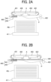
- FIG. 2A is an explanatory view for the above configuration with trouble due to an improvement in the rate of conveyance of the conveying roller 422 and an improvement in the rate of guiding of the guide 440 for an improvement in productivity.
- the trouble corresponds to conveyance failure of a sheet on a sheet conveyance path (namely, paper jam).
- the cause of such conveyance failure is as follows.
- the guide member 441 holding the leading end of a sheet accelerates just before arrival of the sheet at the position of stacking, so that the guide member 441 separates from the leading end of the sheet to cause the sheet to land at the position of stacking.
- FIG. 2B is an explanatory view for such an example.
- a line unit 500 includes a wire as lines extending above the guide path based on the guide member 441.
- the line unit 500 restricts the height of rising of the leading end of the sheet due to air resistance after the sheet separates from the guide member 441. That is, the line unit 500 functions to inhibit the leading end of the sheet from rising. Such rising inhibition prevents conveyance failure with the upper structure catching the edge of the leading end of the sheet.
- the belt 430 is provided with a single guide 440.
- multiple guides 440 may be provided.
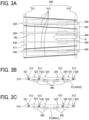
- FIGS. 3A to 3C are explanatory views for the line unit 500.
- FIG. 3A is a bottom view of the line unit 500.
- FIG. 3B is a left side view of the line unit 500 with a sheet having a wide width and having its leading end restricted from rising.
- FIG. 3C is a left side view of the line unit 500 with a sheet having a narrow width and having its leading end restricted from rising.
- the line unit 500 includes multiple wires 513 each as a lines extending in the conveyance direction. In the illustrated example, four wires 513 are provided.
- a hollow arrow B indicates the conveyance direction (direction of sheet guiding).
- the wires 513 are an example of a line.
- the line unit 500 includes an upstream wire positional adjustment plate 510 and a downstream wire positional adjustment plate 511.
- the wires 513 each have its upstream end and downstream end located at the upstream wire positional adjustment plate 510 and the downstream wire positional adjustment plate 511, respectively.
- the positional adjustment plates each include recesses 521 to 528 as wire holders. Each wire may have its ends retained directly by the positional adjustment plates. Alternatively, the positional adjustment plates may each have a function of widthwise positioning the wires each having its ends retained at other places.
- FIG. 3A illustrates four belts 430 and four guides 440, in addition to the line unit 500.
- FIG. 3A further illustrates the table 411 and the conveying roller 422.
- the belts 430 are disposed widthwise at intervals in order not to block the air blown from the blower 450.
- the wires 513 are disposed widthwise at intervals.
- the blower 450 blows air downward as indicated with a hollow arrow A to enhance the productivity of the apparatus or to cause the sheet to have a stable landed pose. As illustrated, air blowing perpendicular to the surface of the sheet is most effective.
- the interval between each of the multiple wires 513 disposed widthwise is smaller than the length in the width direction of a sheet narrowest in width from among sheets to be used.
- two or more wires can be used to control the pose of the sheet.
- the wires 513 are disposed at intervals in the width direction intersecting the conveyance direction, and the interval between the outer wires 513 and the interval between the inner wires 513 increase downstream in the conveyance direction.
- the leading end of the sheet rises and comes in contact with any of the wires 513, the leading end of the sheet is hardly caught by the wire 513.
- each wire 513 can be changed stepwise with the recesses 521 to 528.
- the interval between each wire can be manually changed depending on multiple sizes of sheets. Note that, in the example of FIGS. 3A to 3C , when the downstream end of each wire 513 is moved to the next empty recess closer to the center, all the wires are parallel as a whole.
- the sheet stacker (400) includes: a loader (401) to which a sheet bundle is to be loaded; a guide (423) to: receive a leading end of a sheet conveyed to an area above the loader (401); and guide the sheet along a guide path above the loader in a conveyance direction; a blower (450) disposed above the guide path of the guide (423) to blow air downward to the sheet; and multiple lines (513): disposed above the guide path of the guide (423); and extending in a direction inclined relative to the conveyance direction.
- the multiple lines (513) are disposed apart from each other with an interval in a width direction intersecting the conveyance direction, and the interval increases toward downstream in the conveyance direction.
- the sheet stacker (400) includes: an upstream plate (510) disposed at an upstream end of the guide path and extending in the width direction, the upstream plate (510) including first recesses (521 to 528) to hold an upstream end of the multiple lines; and a downstream plate (511) disposed at a downstream end of the guide path and extending in the width direction, the downstream plate (511) including second recesses (521 to 528) to hold a downstream end of the multiple lines.
- the positions of the multiple lines (513) in the width direction are variable in response to an arrangement of the multiple lines in the first recesses of the upstream plate and the second recesses of the downstream plate.
- the sheet stacker (400) includes a position changer (600) to change each of positions of the multiple lines (513) in the width direction.
- the multiple lines (513) respectively include multiple wires.
- the guide (423) includes: multiple belts (430) stretched around a driving roller (431) and a driven roller (432) in the conveyance direction; and multiple guide members (441) respectively attached to the multiple belts (430), each of the multiple guide member 441 having a gap into which a leading end of the sheet P is insertable, and the multiple lines are disposed above the guide member.
- the multiple lines (513) are arranged in a horizontal plane.
- FIG. 4 is an explanatory view for a modification.
- the positions of the downstream ends in the conveyance direction of two inner wires 513 from among four wires 513 can be changed widthwise. Specifically, the positionally variable downstream ends of the inner wires 513 are secured to a front slider 552 and a rear slider 553 supported movably on a shaft member 550. The downstream ends of two outer wires 513 from among the four wires 513 are secured to a front attachment 551 and a rear attachment 554 secured to the shaft member 550.
- the front slider 552 and the rear slider 553 engage, respectively, with a front rack 560 and a rear rack 561 that are slidable by a pinion 562 for a movement motor 613.
- the front slider 552 and the rear slider 553 can move due to rotation of the pinion 562 by the movement motor 613 such that the interval between the two inner wires 513 is changed.
- a motor drive circuit 612 for the movement motor 613 is connected to a controller 611 to which an operation panel 610 is connected.
- sheet type information such as size information
- control is performed based on pinion rotation operation position information stored in association with the sheet type information.
- downstream ends of the two inner wires are variable in position.
- the outer wires may be variable in position.
- the corresponding upstream ends in the conveyance direction may be variable in position.
- a mechanism enabling changes in position is not limited to a rack-and-pinion mechanism and thus may be a different type of mechanism, such as a recirculating ball and nut type of mechanism or a solenoid type of mechanism.
- effects in the embodiments of the present embodiment correspond to most favorable effects from the present embodiment.
- effects according to the present embodiment are not limited to the effects in the embodiments of the present embodiment.
- a sheet stacker (400) includes: a loader (401) to which a sheet bundle is to be loaded; a guide (423) configured to receive a leading end of a sheet conveyed to an area above the loader (401) to guide the sheet downstream in a conveyance direction; a blower (450) disposed above a guide path based on the guide (423), the blower (450) being configured to blow air to the sheet; and multiple lines (513) disposed above the guide path based on the guide (423), the multiple lines (513) extending in the conveyance direction.
- conveyance failure with an upper structure catching the edge of the leading end of the sheet is prevented.
- the multiple lines (513) is disposed with an interval between the multiple lines (513) in a width direction intersecting the conveyance direction, and the interval increases downstream in the conveyance direction. According to Aspect 2, even when the leading end of the sheet rises and comes in contact with any of the lines, the leading end of the sheet is hardly caught by the lines.
- the multiple lines (513) is disposed with an interval between the multiple lines (513) in a width direction intersecting the conveyance direction, and the interval is smaller than a length in the width direction of the sheet. According to Aspect 3, even when the leading end of the sheet rises, the pose of the sheet can be controlled.
- the multiple lines (513) is disposed with an interval between the multiple lines (513) in a width direction intersecting the conveyance direction, and each of the multiple lines (513) is variable stepwise in position in the width direction. According to Aspect 4, with a simple configuration, multiple sizes of sheets can be dealt with.
- the sheet stacker (400) of any one of Aspects 1 to 4 further includes a position changing means (600), in which the multiple lines (513) is disposed with an interval between the multiple lines (513) in a width direction intersecting the conveyance direction, and the position changing means (600) is configured to change a position in the width direction of each of the multiple lines (513).
- a position changing means (600) in which the multiple lines (513) is disposed with an interval between the multiple lines (513) in a width direction intersecting the conveyance direction, and the position changing means (600) is configured to change a position in the width direction of each of the multiple lines (513).
- a printing apparatus (1) includes the sheet stacker (400) of any one of Aspects 1 to 5. According to Aspect 6, conveyance failure with an upper structure catching the edge of the leading end of the sheet can be prevented, leading to an enhancement in productivity with an improvement in the rate of sheet conveyance.
Landscapes
- Engineering & Computer Science (AREA)
- Mechanical Engineering (AREA)
- Pile Receivers (AREA)
- Feeding Of Articles By Means Other Than Belts Or Rollers (AREA)
Abstract
A sheet stacker (400) includes: a loader (401) to which a sheet bundle is to be loaded; a guide (423) to: receive a leading end of a sheet conveyed to an area above the loader (401); and guide the sheet along a guide path above the loader in a conveyance direction; a blower (450) disposed above the guide path of the guide (423) to blow air downward to the sheet; and multiple lines (513): disposed above the guide path of the guide (423); and extending in a direction inclined relative to the conveyance direction.
Description
- The present embodiment relates to a sheet stacker and a printing apparatus.
- Conventionally, known has been a sheet stacker including a load section to which a sheet bundle is to be loaded, a guiding means that receives the leading end of a sheet conveyed to a space above the load section to guide the sheet downstream in the direction of sheet conveyance, and a blowing means that is disposed above a guide path based on the guiding means and blows air to the sheet. For example, Patent Literature 1 discloses such a sheet stacker, in which the blowing means starts to blow air when the guiding means separates from the leading end of a sheet.
- However, an increase in the rate of sheet conveyance to a space above the load section for an improvement in productivity causes conveyance failure.
- In an aspect of the present disclosure, a sheet stacker includes: a loader to which a sheet bundle is to be loaded; a guide to: receive a leading end of a sheet conveyed to an area above the loader; and guide the sheet along a guide path above the loader in a conveyance direction; a blower disposed above the guide path of the guide to blow air downward to the sheet; and multiple lines: disposed above the guide path of the guide; and extending in a direction inclined relative to the conveyance direction.
- A more complete appreciation of embodiments of the present disclosure and many of the attendant advantages and features thereof can be readily obtained and understood from the following detailed description with reference to the accompanying drawings, wherein:
-
FIGS. 1A and 1B are explanatory views for a printing apparatus according to an embodiment; -
FIGS. 2A and 2B are explanatory views for main parts of the printing apparatus according to the embodiment; -
FIGS. 3A to 3C are explanatory views for a line unit; and -
FIG. 4 is an explanatory view for a modification. - The accompanying drawings are intended to depict embodiments of the present disclosure and should not be interpreted to limit the scope thereof. The accompanying drawings are not to be considered as drawn to scale unless explicitly noted. Also, identical or similar reference numerals designate identical or similar components throughout the several views.
- In describing embodiments illustrated in the drawings, specific terminology is employed for the sake of clarity. However, the disclosure of this specification is not intended to be limited to the specific terminology so selected and it is to be understood that each specific element includes all technical equivalents that have a similar function, operate in a similar manner, and achieve a similar result.
- Referring now to the drawings, embodiments of the present disclosure are described below. As used herein, the singular forms "a," "an," and "the" are intended to include the plural forms as well, unless the context clearly indicates otherwise.
- Embodiments of the present embodiment will be described below with reference to the accompanying drawings. An exemplary printing apparatus according to the present embodiment will be described with reference to
FIGS. 1A and 1B. FIG. 1A is a schematic explanatory view for the printing apparatus.FIG. 1B is an enlarged view of part of the printing apparatus. - A printing apparatus 1 includes a
loader 10, aprinter 20, adryer 30, and anunloader 40 as a sheet stacker according to the present embodiment. In the printing apparatus 1, theprinter 20 applies liquid to a sheet P loaded from theloader 10 to perform desired printing, and thedryer 30 dries the liquid having adhered to the sheet P. Then, the sheet P is ejected to theunloader 40. - The
loader 10 includes aload tray 11 on which multiple sheets P can be loaded, afeeder 12 that separates a sheet P from the multiple sheets P on theload tray 11 to feed the sheet P, and aregistration roller pair 13 that feeds the sheet P to theprinter 20. - As the
feeder 12, used can be any feeder, such as a feeder including a roller or roller or a feeder based on air suction. After the leading end of the sheet P fed from theload tray 11 by thefeeder 12 reaches theregistration roller pair 13, theregistration roller pair 13 drives at a predetermined timing to feed the sheet P to theprinter 20. - The
printer 20 includes asheet conveyor 21 that conveys the sheet P. Thesheet conveyor 21 includes adrum 51 as a bearer (rotator) that rotates while bearing the sheet P on its circumferential face and asucker 52 as a suction means that generates suction force on the circumferential face of thedrum 51. - The
printer 20 includes aliquid discharger 22 that discharges liquid to the sheet P borne on thedrum 51 of thesheet conveyor 21. - The
printer 20 includes adelivery barrel 24 that receives the fed sheet P and delivers the sheet P to thedrum 51 and arelay barrel 25 that relays the sheet P conveyed by thedrum 51 to thedryer 30. - The sheet P conveyed from the
loader 10 to theprinter 20 is conveyed in accordance with rotation of thedelivery barrel 24 while the leading end of the sheet P is being gripped by a gripping means (sheet gripper) with which thedelivery barrel 24 is provided. The sheet P conveyed by thedelivery barrel 24 is delivered to thedrum 51 at a position opposed to thedrum 51. - The
drum 51 has its surface provided with a gripping means (sheet gripper). Thus, the leading end of the sheet P is gripped by the gripping means (sheet gripper). Thedrum 51 has its surface having multiple dispersed suction holes. Thesucker 52 as a suction means generates suction air currents inward through the desired suction holes of thedrum 51. - Then, the sheet P delivered from the
delivery barrel 24 to thedrum 51 is conveyed in accordance with rotation of thedrum 51 while being attracted and borne on thedrum 51 due to the suction air currents by thesucker 52, with its leading end gripped by the sheet gripper. - The
liquid discharger 22 includes discharge units 23 (23A to 23F) as liquid discharge means. For example, thedischarge units discharge units liquid discharger 22 can further include a discharge unit that discharges processing liquid, such as surface coating liquid. - The discharge units 23 are each, for example, a full-line type of head including multiple liquid discharge heads disposed on a base member, in which each liquid discharge head includes a nozzle array in which multiple nozzles is arrayed.
- The discharge operation of each discharge unit 23 in the
liquid discharger 22 is controlled based on a drive signal corresponding to print information. At the time of passage of the sheet P borne on thedrum 51 through a region facing theliquid discharger 22, the discharge units 23 each discharge liquid in the corresponding color to print, on the sheet P, an image corresponding to the print information. - The
dryer 30 includes adrying mechanism 31 that dries the liquid having adhered on the sheet P due to theprinter 20 and asuction conveyance mechanism 32 that conveys the sheet P conveyed from theprinter 20 while suctioning the sheet P. - After the
suction conveyance mechanism 32 receives the sheet P conveyed from theprinter 20, the sheet P is conveyed while passing under thedrying mechanism 31 and then is delivered to theunloader 40. - At the time of passage of the sheet P under the
drying mechanism 31, the liquid on the sheet P is subjected to drying. Thus, the liquid component, such as water, in the liquid evaporates, so that the colorant contained in the liquid is fixed on the sheet P. In addition, the sheet P is inhibited from curling. - The
unloader 40 is achieved with the sheet stacker according to the present embodiment and includes astack section 401 as a loader to which a sheet bundle PB is to be loaded. The sheet P conveyed from thedryer 30 is stacked in order on thestack section 401 for retention. - Note that, for example, the printing apparatus 1 can include a pre-processing unit that is disposed upstream of the
printer 20 and performs pre-processing to the sheet P and a post-processing unit that is disposed between thedryer 30 and theunloader 40 and performs post-processing to the sheet P to which the liquid has adhered. - An exemplary pre-processing unit performs pre-coating such that the sheet P is applied with processing liquid that reacts with the liquid to inhibit bleeding. An exemplary post-processing unit performs sheet reverse conveying such that the sheet P subjected to printing by the
printer 20 is reversed and then is re-fed to theprinter 20 for double-sided printing of the sheet P. Another exemplary post-processing unit performs processing to bind multiple sheets P. - Note that, in the present embodiment, the printing apparatus has been exemplarily described as an inkjet recording apparatus. The "printing apparatus" is not limited to an apparatus that includes a liquid discharge head that discharges liquid to the face to be dried of a sheet member and visualizes a meaningful image, such as a character or a figure, with the discharged liquid and thus may be, for example, an apparatus that forms a meaningless pattern. The material of such a sheet member is not limited and may be any material to which liquid can adhere even temporarily, such as paper, thread, fiber, fabric, leather, metal, plastic, glass, wood, or ceramic. For example, the material may be any material used for film products, cloth products for clothing, building materials such as wallpaper or flooring, or leather products. The "printing apparatus" can include means for feeding a medium to which liquid can adhere, means for conveying a medium to which liquid can adhere, means for ejecting a medium to which liquid can adhere, a pre-processing device, and a post-processing device.
- The "liquid" may have any viscosity or surface tension, provided that the liquid can be discharged from a head. Such liquid is preferably, but not particularly limited to, not more than 30 mPa·s in viscosity at normal temperature and normal pressure or due to heating or cooling. More specific examples of the liquid include a solution, a suspension, and an emulsion that contain a solvent, such as water or an organic solvent, a colorant, such as dye or pigment, a functional material, such as a polymerizable compound, resin, or a surfactant, a biocompatible material, such as deoxyribonucleic acid (DNA), an amino acid, protein, or calcium, or an edible material, such as a natural pigment. Such a solution, a suspension, and an emulsion can be used, for example, for inkjet inks or surface processing liquids.
- Although the printer including liquid discharge means has been exemplarily described, means different from such liquid discharge means may be provided for printing.
- Next, a sheet stacker including a sheet guide and a sheet conveyor according to an embodiment of the present embodiment will be described with reference to
FIG. 1B. FIG. 1B is an explanatory view for the sheet stacker. - A
sheet stacker 400 includes astack section 401 and asheet conveyor 402. Thestack section 401 serves as a loader to which a sheet bundle PB is to be loaded. Thesheet conveyor 402 conveys a sheet P to thestack section 401. - The
stack section 401 includes a table 411 on which the sheet bundle PB is to be loaded, a front fence (jogger) 412, arear fence 413, and lateral fences. - The
sheet conveyor 402 includes conveyingrollers dryer 30 and asheet guide 423 as a sheet guide according to the present embodiment. - The
sheet guide 423 receives the leading end (downstream end) of the sheet P being conveyed from the conveyingroller 422 to thestack section 401 and guides the sheet P downstream in the conveyance direction. - The
sheet guide 423 includes anendless belt 430 stretched around a drivingroller 431 and a drivenroller 432 and aguide 440 attached to thebelt 430. Theguide 440 includes aguide member 441 and anattachment 442 to hold the downstream end of the sheet P. Such guides 440 can be attached to multiple places on the belt 430 (two places in the example ofFIG. 1B ). - In response to elapse of a certain time after detection of the sheet P upstream of the conveying
roller 422, thebelt 430 of thesheet guide 423 runs circumferentially, so that the leading end of the sheet P is inserted into theguide member 441 of eitherguide 440 due to the difference in linear speed between theguide member 441 and the conveyingroller 422. Thesheet guide 423 may be referred to simply as a "guide". - Then, due to the circumferential running of the
belt 430, while holding the leading end of the sheet P, theguide member 441 moves downstream in the conveyance direction to guide the sheet P. - The
guide member 441 has a gap larger than the thickness of the sheet P such that the leading end of the sheet P can be inserted into the gap, but has no gripping force, such as a force to grip the sheet P. Theguide member 441 serves to guide the leading end of the sheet P and functions to inhibit the portion ranging from the leading end to an intermediate of the sheet P from fluttering. Note that theguide member 441 may include a clip having a gripping force to grip the leading end of the sheet P. - In response to arrival of the
guide member 441 at the position of guide termination, theguide member 441 is made higher in linear speed than the conveyingroller 422. Thus, the leading end of the sheet P separates from theguide member 441, so that the sheet P falls onto thestack section 401 for stacking. Thestack section 401 is an example of a loader to load and stacks the sheet P. - Provided is a
blower 450 as a blower that blows air to the sheet P. Theblower 450 located above thestack section 401 as a loader and on the downstream side in the conveyance direction of the position at which theguide member 441 of eitherguide 440 receives the leading end of the sheet P blows air to the sheet P. -
FIG. 2A is an explanatory view for the above configuration with trouble due to an improvement in the rate of conveyance of the conveyingroller 422 and an improvement in the rate of guiding of theguide 440 for an improvement in productivity. The trouble corresponds to conveyance failure of a sheet on a sheet conveyance path (namely, paper jam). The cause of such conveyance failure is as follows. Theguide member 441 holding the leading end of a sheet accelerates just before arrival of the sheet at the position of stacking, so that theguide member 441 separates from the leading end of the sheet to cause the sheet to land at the position of stacking. The leading end of the sheet separated from theguide member 441 in high-rate conveyance of the sheet rises due to air resistance and then the edge of the leading end of the sheet is caught by an upper structure, resulting in occurrence of conveyance failure. In particular, conveyance failure based on a sheet low in rigidity tends to occur. - In the present embodiment, for prevention of conveyance failure due to the rise of the leading end of a sheet, multiple lines extending in the conveyance direction is disposed above a guide path based on the
guide member 441 of such aguide 440.FIG. 2B is an explanatory view for such an example. Aline unit 500 includes a wire as lines extending above the guide path based on theguide member 441. Theline unit 500 restricts the height of rising of the leading end of the sheet due to air resistance after the sheet separates from theguide member 441. That is, theline unit 500 functions to inhibit the leading end of the sheet from rising. Such rising inhibition prevents conveyance failure with the upper structure catching the edge of the leading end of the sheet. - Referring to
FIG. 2B , as an example, thebelt 430 is provided with asingle guide 440. However, as illustrated inFIG. 1B ,multiple guides 440 may be provided. -
FIGS. 3A to 3C are explanatory views for theline unit 500.FIG. 3A is a bottom view of theline unit 500.FIG. 3B is a left side view of theline unit 500 with a sheet having a wide width and having its leading end restricted from rising.FIG. 3C is a left side view of theline unit 500 with a sheet having a narrow width and having its leading end restricted from rising. Theline unit 500 includesmultiple wires 513 each as a lines extending in the conveyance direction. In the illustrated example, fourwires 513 are provided. A hollow arrow B indicates the conveyance direction (direction of sheet guiding). Thewires 513 are an example of a line. - The
line unit 500 includes an upstream wirepositional adjustment plate 510 and a downstream wirepositional adjustment plate 511. In the conveyance direction, thewires 513 each have its upstream end and downstream end located at the upstream wirepositional adjustment plate 510 and the downstream wirepositional adjustment plate 511, respectively. As illustrated inFIG. 3B or 3C , the positional adjustment plates each include recesses 521 to 528 as wire holders. Each wire may have its ends retained directly by the positional adjustment plates. Alternatively, the positional adjustment plates may each have a function of widthwise positioning the wires each having its ends retained at other places. -
FIG. 3A illustrates fourbelts 430 and fourguides 440, in addition to theline unit 500.FIG. 3A further illustrates the table 411 and the conveyingroller 422. Thebelts 430 are disposed widthwise at intervals in order not to block the air blown from theblower 450. For a similar reason, thewires 513 are disposed widthwise at intervals. Theblower 450 blows air downward as indicated with a hollow arrow A to enhance the productivity of the apparatus or to cause the sheet to have a stable landed pose. As illustrated, air blowing perpendicular to the surface of the sheet is most effective. - As illustrated in
FIG. 3C , the interval between each of themultiple wires 513 disposed widthwise is smaller than the length in the width direction of a sheet narrowest in width from among sheets to be used. Thus, when the leading end of the sheet rises, two or more wires can be used to control the pose of the sheet. Thewires 513 are disposed at intervals in the width direction intersecting the conveyance direction, and the interval between theouter wires 513 and the interval between theinner wires 513 increase downstream in the conveyance direction. Thus, even when the leading end of the sheet rises and comes in contact with any of thewires 513, the leading end of the sheet is hardly caught by thewire 513. - As illustrated in
FIG. 3B or 3C , the position in the width direction of eachwire 513 can be changed stepwise with therecesses 521 to 528. Thus, provided can be a simple configuration in which the interval between each wire can be manually changed depending on multiple sizes of sheets. Note that, in the example ofFIGS. 3A to 3C , when the downstream end of eachwire 513 is moved to the next empty recess closer to the center, all the wires are parallel as a whole. - The sheet stacker (400) includes: a loader (401) to which a sheet bundle is to be loaded; a guide (423) to: receive a leading end of a sheet conveyed to an area above the loader (401); and guide the sheet along a guide path above the loader in a conveyance direction; a blower (450) disposed above the guide path of the guide (423) to blow air downward to the sheet; and multiple lines (513): disposed above the guide path of the guide (423); and extending in a direction inclined relative to the conveyance direction.
- The multiple lines (513) are disposed apart from each other with an interval in a width direction intersecting the conveyance direction, and the interval increases toward downstream in the conveyance direction.
- The sheet stacker (400) includes: an upstream plate (510) disposed at an upstream end of the guide path and extending in the width direction, the upstream plate (510) including first recesses (521 to 528) to hold an upstream end of the multiple lines; and a downstream plate (511) disposed at a downstream end of the guide path and extending in the width direction, the downstream plate (511) including second recesses (521 to 528) to hold a downstream end of the multiple lines. The positions of the multiple lines (513) in the width direction are variable in response to an arrangement of the multiple lines in the first recesses of the upstream plate and the second recesses of the downstream plate.
- The sheet stacker (400) includes a position changer (600) to change each of positions of the multiple lines (513) in the width direction. The multiple lines (513) respectively include multiple wires. The guide (423) includes: multiple belts (430) stretched around a driving roller (431) and a driven roller (432) in the conveyance direction; and multiple guide members (441) respectively attached to the multiple belts (430), each of the
multiple guide member 441 having a gap into which a leading end of the sheet P is insertable, and the multiple lines are disposed above the guide member. The multiple lines (513) are arranged in a horizontal plane. -
FIG. 4 is an explanatory view for a modification. - The positions of the downstream ends in the conveyance direction of two
inner wires 513 from among fourwires 513 can be changed widthwise. Specifically, the positionally variable downstream ends of theinner wires 513 are secured to afront slider 552 and arear slider 553 supported movably on ashaft member 550. The downstream ends of twoouter wires 513 from among the fourwires 513 are secured to afront attachment 551 and arear attachment 554 secured to theshaft member 550. - The
front slider 552 and therear slider 553 engage, respectively, with afront rack 560 and arear rack 561 that are slidable by apinion 562 for amovement motor 613. Thus, thefront slider 552 and therear slider 553 can move due to rotation of thepinion 562 by themovement motor 613 such that the interval between the twoinner wires 513 is changed. - A
motor drive circuit 612 for themovement motor 613 is connected to acontroller 611 to which anoperation panel 610 is connected. For changes in the positions of the downstream ends of the twoinner wires 513 based on control of themovement motor 613, sheet type information, such as size information, is acquired from operation information on theoperation panel 610 and then control is performed based on pinion rotation operation position information stored in association with the sheet type information. Use of such size information enables automatic movement of the fourwires 513 to positions in the width direction that correspond to the size of each sheet (particularly, width size) and are suitable to restrict rising of the leading end of each sheet due to air resistance. - In the example, the downstream ends of the two inner wires are variable in position. Instead of this, similarly, the outer wires may be variable in position. Furthermore, instead of or in addition to such downstream ends in the conveyance direction, the corresponding upstream ends in the conveyance direction may be variable in position. Furthermore, a mechanism enabling changes in position is not limited to a rack-and-pinion mechanism and thus may be a different type of mechanism, such as a recirculating ball and nut type of mechanism or a solenoid type of mechanism.
- Preferred embodiments of the present embodiment have been described above. However, the present embodiment is not limited to the particular embodiments. Unless otherwise particularly limited in the above description, various modifications and alterations can be made without departing from the scope of the gist of the present embodiment in the claims.
- The effects in the embodiments of the present embodiment correspond to most favorable effects from the present embodiment. Thus, effects according to the present embodiment are not limited to the effects in the embodiments of the present embodiment.
- The above description is exemplary, and the following aspects of the present embodiment have respective particular effects. Reference signs in parentheses with which constituents are denoted in each aspect indicate the corresponding members. However, the constituents are not limited to the members.
- According to Aspect 1, a sheet stacker (400) includes: a loader (401) to which a sheet bundle is to be loaded; a guide (423) configured to receive a leading end of a sheet conveyed to an area above the loader (401) to guide the sheet downstream in a conveyance direction; a blower (450) disposed above a guide path based on the guide (423), the blower (450) being configured to blow air to the sheet; and multiple lines (513) disposed above the guide path based on the guide (423), the multiple lines (513) extending in the conveyance direction. According to Aspect 1, conveyance failure with an upper structure catching the edge of the leading end of the sheet is prevented.
- According to Aspect 2, in the sheet stacker (400) of Aspect 1, the multiple lines (513) is disposed with an interval between the multiple lines (513) in a width direction intersecting the conveyance direction, and the interval increases downstream in the conveyance direction. According to Aspect 2, even when the leading end of the sheet rises and comes in contact with any of the lines, the leading end of the sheet is hardly caught by the lines.
- According to Aspect 3, in the sheet stacker (400) of Aspect 1 or 2, the multiple lines (513) is disposed with an interval between the multiple lines (513) in a width direction intersecting the conveyance direction, and the interval is smaller than a length in the width direction of the sheet. According to Aspect 3, even when the leading end of the sheet rises, the pose of the sheet can be controlled.
- According to Aspect 4, in the sheet stacker (400) of any one of Aspects 1 to 3, the multiple lines (513) is disposed with an interval between the multiple lines (513) in a width direction intersecting the conveyance direction, and each of the multiple lines (513) is variable stepwise in position in the width direction. According to Aspect 4, with a simple configuration, multiple sizes of sheets can be dealt with.
- According to Aspect 5, the sheet stacker (400) of any one of Aspects 1 to 4 further includes a position changing means (600), in which the multiple lines (513) is disposed with an interval between the multiple lines (513) in a width direction intersecting the conveyance direction, and the position changing means (600) is configured to change a position in the width direction of each of the multiple lines (513). According to Aspect 5, multiple sizes of sheets can be dealt automatically with.
- According to Aspect 6, a printing apparatus (1) includes the sheet stacker (400) of any one of Aspects 1 to 5. According to Aspect 6, conveyance failure with an upper structure catching the edge of the leading end of the sheet can be prevented, leading to an enhancement in productivity with an improvement in the rate of sheet conveyance.
Claims (10)
- A sheet stacker (400) comprising:a loader (401) to which a sheet bundle is to be loaded;a guide (423) to:receive a leading end of a sheet conveyed to an area above the loader (401); andguide the sheet along a guide path above the loader in a conveyance direction;a blower (450) disposed above the guide path of the guide (423) to blow air downward to the sheet; andmultiple lines (513):disposed above the guide path of the guide (423); andextending in a direction inclined relative to the conveyance direction.
- The sheet stacker (400) according to claim 1,wherein the multiple lines (513) are disposed apart from each other with an interval in a width direction intersecting the conveyance direction, andthe interval increases toward downstream in the conveyance direction.
- The sheet stacker (400) according to claim 1 or 2,
wherein the interval is smaller than a length of the sheet in the width direction. - The sheet stacker (400) according to any one of claims 1 to 3, further comprising:an upstream plate (510) disposed at an upstream end of the guide path and extending in the width direction, the upstream plate (510) including first recesses (521 to 528) to hold an upstream end of the multiple lines; anda downstream plate (511) disposed at a downstream end of the guide path and extending in the width direction, the downstream plate (511) including second recesses (521 to 528) to hold a downstream end of the multiple lines,wherein positions of the multiple lines (513) in the width direction are variable in response to an arrangement of the multiple lines in the first recesses of the upstream plate and the second recesses of the downstream plate.
- The sheet stacker (400) according to any one of claims 1 to 4, further comprising
a position changer (600) to change each of positions of the multiple lines (513) in the width direction. - The sheet stacker (400) according to any one of claims 1 to 5,
Wherein the multiple lines (513) respectively include multiple wires. - The sheet stacker (400) according to any one of claims 1 to 6,
wherein the guide (423) includes:multiple belts (430) stretched around a driving roller (431) and a driven roller (432) in the conveyance direction; andmultiple guide members (441) respectively attached to the multiple belts (430), each of the multiple guide member 441 having a gap into which a leading end of the sheet P is insertable, andthe multiple lines are disposed above the guide member. - The sheet stacker (400) according to any one of claims 1 to 8,
wherein the multiple lines (513) are arranged in a horizontal plane. - The sheet stacker (400) according to any one of claims 1 to 8,
wherein the multiple lines (513) are between the multiple lines in the width direction. - A printing apparatus (1) comprising the sheet stacker (400) according to any one of claims 1 to 9.
Applications Claiming Priority (1)
| Application Number | Priority Date | Filing Date | Title |
|---|---|---|---|
| JP2023085515A JP2024168654A (en) | 2023-05-24 | 2023-05-24 | Sheet stacking device and printing device |
Publications (1)
| Publication Number | Publication Date |
|---|---|
| EP4467495A1 true EP4467495A1 (en) | 2024-11-27 |
Family
ID=91193504
Family Applications (1)
| Application Number | Title | Priority Date | Filing Date |
|---|---|---|---|
| EP24177024.7A Pending EP4467495A1 (en) | 2023-05-24 | 2024-05-21 | Sheet stacker and printing apparatus |
Country Status (3)
| Country | Link |
|---|---|
| US (1) | US12545545B2 (en) |
| EP (1) | EP4467495A1 (en) |
| JP (1) | JP2024168654A (en) |
Citations (4)
| Publication number | Priority date | Publication date | Assignee | Title |
|---|---|---|---|---|
| US4317563A (en) * | 1979-02-14 | 1982-03-02 | Veb Kombinat Polygraph "Werner Lamberz" Leipzig | Blowing device in sheet deliverers of sheet processing machines |
| DE102011017217A1 (en) * | 2011-04-15 | 2012-10-18 | Mühlbauer Ag | Apparatus and method for depositing sheet products |
| US20200137246A1 (en) * | 2018-10-31 | 2020-04-30 | Hewlett-Packard Development Company, L.P. | Media registration system with media sensing |
| US20210395033A1 (en) * | 2020-06-23 | 2021-12-23 | Ricoh Company, Ltd. | Sheet guide, sheet conveyor, sheet stacker, and printer |
Family Cites Families (13)
| Publication number | Priority date | Publication date | Assignee | Title |
|---|---|---|---|---|
| DE2552998C2 (en) * | 1975-11-26 | 1983-11-10 | Heidelberger Druckmaschinen Ag, 6900 Heidelberg | Sheet delivery for rotary printing machines |
| US4643414A (en) * | 1984-04-07 | 1987-02-17 | Miller-Johannisberg Druckmaschinen Gmbh | Sheet-delivery control and regulating apparatus |
| DE4201480C2 (en) * | 1992-01-21 | 1997-02-13 | Heidelberger Druckmasch Ag | Device for depositing printed sheets on a stack |
| DE10007249A1 (en) * | 1999-03-29 | 2000-10-05 | Heidelberger Druckmasch Ag | Sheet output assembly for a sheet printer has an air flow mechanism comprised of axial blowers that re-circulate the air, preventing any dust from escaping from the output housing |
| JP4495413B2 (en) | 2003-06-19 | 2010-07-07 | 株式会社小森コーポレーション | Sheet material guide device |
| JP2008094582A (en) | 2006-10-13 | 2008-04-24 | Nisca Corp | Sheet stacking device and image forming device equipped with it |
| US11479433B2 (en) * | 2018-10-30 | 2022-10-25 | Ricoh Company, Ltd. | Sheet conveying device and image forming apparatus incorporating the sheet conveying device |
| JP7435014B2 (en) | 2019-03-20 | 2024-02-21 | 株式会社リコー | Sheet loading device, printing device |
| US11325802B2 (en) | 2019-03-20 | 2022-05-10 | Ricoh Company, Ltd. | Sheet stacker and image forming system incorporating the sheet stacker |
| JP7686985B2 (en) * | 2021-01-22 | 2025-06-03 | 株式会社リコー | Sheet stacking device, printing device |
| JP7757710B2 (en) | 2021-10-27 | 2025-10-22 | 株式会社リコー | Sheet stacking device and image forming apparatus |
| JP7844944B2 (en) | 2022-03-09 | 2026-04-14 | 株式会社リコー | Sheet loading device and image forming apparatus |
| JP2024154699A (en) * | 2023-04-19 | 2024-10-31 | 株式会社リコー | Sheet stacking device and image forming apparatus |
-
2023
- 2023-05-24 JP JP2023085515A patent/JP2024168654A/en active Pending
-
2024
- 2024-05-16 US US18/665,593 patent/US12545545B2/en active Active
- 2024-05-21 EP EP24177024.7A patent/EP4467495A1/en active Pending
Patent Citations (4)
| Publication number | Priority date | Publication date | Assignee | Title |
|---|---|---|---|---|
| US4317563A (en) * | 1979-02-14 | 1982-03-02 | Veb Kombinat Polygraph "Werner Lamberz" Leipzig | Blowing device in sheet deliverers of sheet processing machines |
| DE102011017217A1 (en) * | 2011-04-15 | 2012-10-18 | Mühlbauer Ag | Apparatus and method for depositing sheet products |
| US20200137246A1 (en) * | 2018-10-31 | 2020-04-30 | Hewlett-Packard Development Company, L.P. | Media registration system with media sensing |
| US20210395033A1 (en) * | 2020-06-23 | 2021-12-23 | Ricoh Company, Ltd. | Sheet guide, sheet conveyor, sheet stacker, and printer |
Also Published As
| Publication number | Publication date |
|---|---|
| US20240391723A1 (en) | 2024-11-28 |
| US12545545B2 (en) | 2026-02-10 |
| JP2024168654A (en) | 2024-12-05 |
Similar Documents
| Publication | Publication Date | Title |
|---|---|---|
| US11325802B2 (en) | Sheet stacker and image forming system incorporating the sheet stacker | |
| US12024383B2 (en) | Sheet guide, sheet conveyor, sheet stacker, and printer | |
| US8684487B2 (en) | Conveying apparatus, liquid applying apparatus, and image forming apparatus | |
| US8029126B2 (en) | Image forming apparatus | |
| JP7435014B2 (en) | Sheet loading device, printing device | |
| EP2621842B1 (en) | Printing system with sheet conveying device | |
| JP5642747B2 (en) | Image forming apparatus | |
| US11180336B2 (en) | Medium transporting apparatus and post-processing apparatus | |
| US10807824B2 (en) | Medium transporting apparatus and post-processing apparatus | |
| US11104159B2 (en) | Sheet conveying device and image forming system incorporating the sheet conveying device | |
| US12545545B2 (en) | Sheet stacker and printing apparatus | |
| JP7011793B2 (en) | Transport equipment, drying equipment and image forming equipment | |
| US12351412B2 (en) | Conveyance apparatus and printing apparatus | |
| JP2008273663A (en) | Paper receiving device | |
| US11760591B2 (en) | Sheet stacking device and printing apparatus | |
| US11919741B2 (en) | Sheet stacking apparatus and liquid discharging apparatus | |
| US20150273879A1 (en) | Conveyor device and inkjet recording apparatus | |
| CN110950147B (en) | Stackers and Media Handling Units | |
| US20200276836A1 (en) | Medium conveying device and inkjet printer | |
| EP2844491B1 (en) | Inkjet printer with selectable simplex and duplex printing | |
| JP7305994B2 (en) | Sheet material delivery system, printing system | |
| JP2024154699A (en) | Sheet stacking device and image forming apparatus | |
| US20250115449A1 (en) | Sheet stacking apparatus and image forming apparatus | |
| US20240228210A1 (en) | Medium transport device, liquid ejection device, and post-process device | |
| EP3708526A1 (en) | Sheet conveying device and image forming apparatus incorporating the sheet conveying device |
Legal Events
| Date | Code | Title | Description |
|---|---|---|---|
| PUAI | Public reference made under article 153(3) epc to a published international application that has entered the european phase |
Free format text: ORIGINAL CODE: 0009012 |
|
| STAA | Information on the status of an ep patent application or granted ep patent |
Free format text: STATUS: REQUEST FOR EXAMINATION WAS MADE |
|
| 17P | Request for examination filed |
Effective date: 20240521 |
|
| AK | Designated contracting states |
Kind code of ref document: A1 Designated state(s): AL AT BE BG CH CY CZ DE DK EE ES FI FR GB GR HR HU IE IS IT LI LT LU LV MC ME MK MT NL NO PL PT RO RS SE SI SK SM TR |